EP1565898B1 - Modular measuring transducer provided with a galvanically separated sensor - Google Patents
Modular measuring transducer provided with a galvanically separated sensor Download PDFInfo
- Publication number
- EP1565898B1 EP1565898B1 EP03780057A EP03780057A EP1565898B1 EP 1565898 B1 EP1565898 B1 EP 1565898B1 EP 03780057 A EP03780057 A EP 03780057A EP 03780057 A EP03780057 A EP 03780057A EP 1565898 B1 EP1565898 B1 EP 1565898B1
- Authority
- EP
- European Patent Office
- Prior art keywords
- electronic module
- module
- sensor module
- transmitter
- sensor
- Prior art date
- Legal status (The legal status is an assumption and is not a legal conclusion. Google has not performed a legal analysis and makes no representation as to the accuracy of the status listed.)
- Expired - Lifetime
Links
- 230000005540 biological transmission Effects 0.000 claims abstract description 14
- 230000000295 complement effect Effects 0.000 claims description 6
- 230000001939 inductive effect Effects 0.000 claims description 5
- 239000000446 fuel Substances 0.000 claims description 3
- 238000013497 data interchange Methods 0.000 abstract 1
- 238000000926 separation method Methods 0.000 abstract 1
- 239000000523 sample Substances 0.000 description 3
- 238000013480 data collection Methods 0.000 description 1
- 230000001419 dependent effect Effects 0.000 description 1
- 238000004880 explosion Methods 0.000 description 1
- 231100001261 hazardous Toxicity 0.000 description 1
- 230000001771 impaired effect Effects 0.000 description 1
- 230000008054 signal transmission Effects 0.000 description 1
- 238000002604 ultrasonography Methods 0.000 description 1
Images
Classifications
-
- G—PHYSICS
- G08—SIGNALLING
- G08C—TRANSMISSION SYSTEMS FOR MEASURED VALUES, CONTROL OR SIMILAR SIGNALS
- G08C17/00—Arrangements for transmitting signals characterised by the use of a wireless electrical link
Definitions
- the present invention relates to a modular transmitter having a sensor module and an electronic module coupled to the sensor module, wherein the sensor module is coupled via a contactless interface to the electronic module, via which the power supply of the sensor module and the data exchange between the sensor module and the electronic module.
- the interface may be designed in the manner described in European patent application no. EP 1 206 012 A2 is described, in particular inductive interfaces appear suitable.
- German Offenlegungsschrift discloses DE 13 703 854 a modular transmitter, in which a sensor is screwed to a measuring head, wherein the measuring head has a transmitting and receiving unit to wirelessly with a central Data collection unit to communicate.
- the probes such as pH electrodes, are not galvanically isolated from the probe. Rather, it is assumed that a normal metallic contact between the measuring head and the probes.
- the present invention is therefore based on the object to provide an electronic module for a modular transmitter, which overcomes the disadvantages of the prior art described.
- the object is achieved by the electronic module according to independent claim 1 and the modular transmitter according to independent claim 5.
- the modular transmitter according to the invention comprises a sensor module for detecting a measured variable and the electronic module according to the invention, wherein the sensor module and the electronic module are coupled to each other via a contactless interface, via which the power supply of the sensor module and the data exchange between the sensor module and the electronic module, wherein the electronic module further comprising a transmitting or transmitting and receiving unit for wireless data exchange with a complementary receiving or receiving and transmitting station.
- the power supply of the electronic module can be done either via a supply cable or self-sufficient, ie, for example, by photocells, by means of a battery or by means of a fuel cell. Of course they are the different forms of energy supply can be combined.
- the wireless data exchange between the electronic module and the complementary receiving or transmitting and receiving unit for example, via radio, ultrasound or light, in particular by means of infrared light.
- the selected type of data transmission depends on the particular circumstances of the application. For use in laboratory operation with short ranges in particular an infrared data transmission seems suitable, with radio transmission being preferred for systems with longer ranges.
- the data transmission over a mobile network or via satellite is suitable.
- the invention can generally be implemented with arbitrary sensors, in particular with potentiometric sensors, turbidity sensors, gas sensors, pressure sensors, level sensors, flow sensors, spectroscopic sensors, photometric sensors, temperature sensors and humidity sensors.
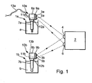
- the measuring arrangement shown comprises two modular transducers, namely a modular opacimeter 1a and a modular pH transmitter 1b.
- the two modular transducers 1a, 1b exchange data with a base station 2.
- the modular opacimeter 1a comprises an electronic module 10a which contains a circuit 8a for processing a signal received from the sensor module 7a Sensor signal includes.
- the circuit 8a may further comprise means for reading device parameters of the electronic module 10a and the sensor module 7a.
- the electronic module 10a comprises a transmission unit 9a for transmitting and receiving data to the base station 2.
- the data transmission unit comprises an infrared transmitter 3a and an infrared receiver 5a, the base station 2 having a complementary receiver 4 and transmitter 6, respectively.
- the data exchange can take place, for example, according to the IrDA standard.
- the power supply of the electronic module 10a takes place via a supply line 13a.
- the supply line 13a is used exclusively for power supply, wherein in a further embodiment, the supply line 13a at the same time redundant for data transmission z.
- B. regulation of the supply current (4 ... 20 mA) or according to the HART standard is used.
- a contactless plug connection is provided, which has a socket 11a provided on the underside of the sensor module 10a, and a plug 12a which is connected to the sensor module 7a. and engaged with the bushing 11a.
- the connector is preferably detachable. Of course, the connector can also be designed vice versa. That from the bottom of the electronic module extends a plug, and the sensor module has a plug head for receiving the plug.
- a first cylindrical coil may be arranged, wherein the plug 12a has a second cylindrical coil which is coaxial with the first cylindrical coil is arranged.
- the plug 12a and the socket 11b each have a coil with a toroidal half, wherein the end surfaces of the toroidal core halves are positioned in alignment with each other closely spaced when the plug is disposed in the socket.
- the inductive energy transfer from the electronic module to the sensor module takes place via an AC signal which is fed by the electronic module.
- the amplitude of the AC signal is preferably modulated (ASK according to the English term amplitude shift keying), but other types of modulation such as pulse width and frequency modulation are conceivable.
- the transmission of data to the sensor module takes place here by direct modulation of the injected AC signal, wherein for data transmission from the sensor module to the electronic module is a load modulation of the AC signal.
- Fig. 1 further shows a modular transmitter 1b, which is designed as a pH transmitter. It has essentially the same structure as the modular turbidity meter 1a, so that reference is made below only to differences from the turbidity meter described above.
- the sensor module 7b comprises for the pH transmitter a pH electrode, which is connected by means of the plug head 12b in the socket 11b of the contactless plug connection with the electronic module 10b.
- the power supply of the modular transmitter 1 b is decentralized, for which purpose a battery 13 b is provided in the housing of the electronic module 10 b.
- the local energy supply via a fuel cell or via a photocell.
- the assignment of the power supply types to the different sensor types is chosen only for illustration purposes and does not describe a mandatory technical connection.
Abstract
Description
Die vorliegende Erfindung betrifft einen modularen Messumformer, der ein Sensormodul und ein mit dem Sensormodul gekoppeltes Elektronikmodul aufweist, wobei das Sensormodul über eine kontaktlose Schnittstelle an das Elektronikmodul gekoppelt ist, über welche die Energieversorgung des Sensormoduls und der Datenaustausch zwischen dem Sensormodul und dem Elektronikmodul erfolgt. Die Schnittstelle kann in der Art gestaltet sein, wie sie in der europäischen Patentanmeldung Nr.
Wenngleich die in der genannten europäischen Patentanmeldung als Steckverbinder offenbarte Schnittstelle die galvanische Entkopplung zwischen dem Sensormodul und dem Elektronikmodul gewährleistet, so erfordert die dort beschriebene Lösung noch die Datenübertragung zwischen dem Elektronikmodul und einer übergeordneten Einheit, beispielsweise einer Warte, über ein Kabel.Although the disclosed as a connector in the said European patent application interface ensures the galvanic decoupling between the sensor module and the electronic module, the solution described therein still requires the data transmission between the electronic module and a higher-level unit, such as a control room, via a cable.
In besonderen Anwendungsfällen ist dies insofern nachteilhaft, als der modulare Messumformer nur schwer zugänglich ist bzw. sehr weit von der übergeordneten Einheit entfernt ist. Zudem besteht die Gefahr, dass der Datenaustausch zwischen der übergeordneten Einheit und dem Messumformer durch Beschädigung des Kabels beeinträchtigt wird. Weiterhin kann es von Nachteil sein, wenn der Messumformer galvanisch an die übergeordnete Einheit gekoppelt ist, insbesondere dann, wenn lokale Potentialschwankungen auftreten können.In special applications, this is disadvantageous in that the modular transmitter is difficult to access or is very far away from the parent unit. In addition, there is a risk that the data exchange between the higher-level unit and the transmitter will be affected by damage to the cable. Furthermore, it can be disadvantageous if the transmitter is galvanically coupled to the higher-level unit, in particular if local potential fluctuations can occur.
Andererseits offenbart die deutsche Offenlegungsschrift
Dies ist insofern nachteilig, als beim Austausch von Messfühlern durch Funkenabriss Explosionsgefahr in gefährdeten Umgebungen besteht. Zudem können die Kontakte zwischen dem Messfühler und dem Messkopf korrodieren, so dass die Signalübertragung beeinträchtigt wird.This is disadvantageous in that there is a risk of explosion in hazardous environments when replacing sensors by spark arrest. In addition, the contacts between the sensor and the measuring head can corrode, so that the signal transmission is impaired.
Ein weiterer modularer Meßumformer ist aus
Der vorliegenden Erfindung liegt daher die Aufgabe zugrunde, ein Elektronikmodul für einen modularen Messumformer bereitzustellen, welches die beschriebenen Nachteile des Standes der Technik überwindet.The present invention is therefore based on the object to provide an electronic module for a modular transmitter, which overcomes the disadvantages of the prior art described.
Die Aufgabe wird erfindungsgemäß gelöst durch das Elektronikmodul gemäß des unabhängigen Patentanspruchs 1 sowie dem modularen Messumformer gemäß unabhängigem Patentanspruchs 5.The object is achieved by the electronic module according to independent claim 1 and the modular transmitter according to independent claim 5.
Der erfindungsgemäße modulare Messumformer umfasst ein Sensormodul zum Erfassen einer Messgröße und das erfindungsgemäße Elektronikmodul, wobei das Sensormodul und das Elektronikmodul über eine kontaktlose Schnittstelle miteinander gekoppelt sind, über welche die Energieversorgung des Sensormoduls und der Datenaustausch zwischen dem Sensormodul und dem Elektronikmodul erfolgt, wobei das Elektronikmodul weiterhin eine Sende- bzw. Sende- und Empfangseinheit zum drahtlosen Datenaustausch mit einer komplementären Empfangs- bzw. Empfangs- und Sendestation aufweist.The modular transmitter according to the invention comprises a sensor module for detecting a measured variable and the electronic module according to the invention, wherein the sensor module and the electronic module are coupled to each other via a contactless interface, via which the power supply of the sensor module and the data exchange between the sensor module and the electronic module, wherein the electronic module further comprising a transmitting or transmitting and receiving unit for wireless data exchange with a complementary receiving or receiving and transmitting station.
Die Energieversorgung des Elektronikmoduls kann entweder über ein Versorgungskabel oder autark, d.h. z. B. durch Photozellen, mittels einer Batterie oder mittels einer Brennstoffzelle erfolgen. Selbstverständlich sind die verschiedenen Formen der Energieversorgung miteinander kombinierbar.The power supply of the electronic module can be done either via a supply cable or self-sufficient, ie, for example, by photocells, by means of a battery or by means of a fuel cell. Of course they are the different forms of energy supply can be combined.
Der drahtlose Datenaustausch zwischen dem Elektronikmodul und der komplementären Empfangs- bzw. Sende- und Empfangseinheit kann beispielsweise über Funk, Ultraschall oder Licht, insbesondere mittels Infrarotlicht erfolgen. Die gewählte Art der Datenübertragung hängt von den besonderen Umständen des Einsatzgebietes ab. Für den Einsatz im Laborbetrieb mit kurzen Reichweiten erscheint insbesondere eine Infrarot-Datenübertragung geeignet, wobei für Systeme mit größeren Reichweiten Funkübertragung vorzuziehen ist. Für besondere Anwendungsfälle ist auch die Datenübertragung über ein Mobilfunknetz oder über Satellit geeignet.The wireless data exchange between the electronic module and the complementary receiving or transmitting and receiving unit, for example, via radio, ultrasound or light, in particular by means of infrared light. The selected type of data transmission depends on the particular circumstances of the application. For use in laboratory operation with short ranges in particular an infrared data transmission seems suitable, with radio transmission being preferred for systems with longer ranges. For special applications, the data transmission over a mobile network or via satellite is suitable.
Die Erfindung ist generell mit beliebigen Sensoren realisierbar, insbesondere mit potentiometrischen Sensoren, Trübungssensoren, Gassensoren, Drucksensoren Füllstandssensoren, Durchflusssensoren, spektroskopischen Sensoren, Photometrischen Sensoren, Temperatursensoren und Feuchtesensoren.The invention can generally be implemented with arbitrary sensors, in particular with potentiometric sensors, turbidity sensors, gas sensors, pressure sensors, level sensors, flow sensors, spectroscopic sensors, photometric sensors, temperature sensors and humidity sensors.
Weitere Vorteile und Gesichtspunkte der vorliegenden Erfindung ergeben sich aus den abhängigen Patentansprüchen und der Beschreibung eines Ausführungsbeispiels in der Zeichnung. Es zeigt:
-
Fig. 1 : Eine Messanordnung mit einem Messumformer gemäß der vorliegenden Erfindung.
-
Fig. 1 : A measuring arrangement with a transmitter according to the present invention.
Die in
Die Energieversorgung des Elektronikmoduls 10a erfolgt über eine Versorgungsleitung 13a. In einer ersten Ausführungsform dient dabei die Versorgungsleitung 13a ausschließlich zur Energieversorgung, wobei in einer weiteren Ausführungsform die Versorgungsleitung 13a zugleich redundant zur Datenübertragung z. B. Regulierung des Versorgungsstroms (4 ... 20 mA) oder nach dem HART-Standard verwendet wird.The power supply of the
Zur Energieversorgung des Sensormoduls und zum Datenaustausch zwischen dem Sensormodul 7a und dem Elektronikmodul 10a ist eine kontaktlose Steckverbindung vorgesehen, welche eine Steckbuchse 11a aufweist, die an der Unterseite des Sensormoduls 10a vorgesehen ist, und einen Stecker 12a, der mit dem Sensormodul 7a verbunden ist, und mit der Buchse 11a in Eingriff gelangt. Die Steckverbindung ist vorzugsweise lösbar. Selbstverständlich kann die Steckverbindung auch umgekehrt gestaltet sein. D.h. von der Unterseite des Elektronikmoduls erstreckt sich ein Stecker, und das Sensormodul weist einen Steckkopf zur Aufnahme des Steckers auf.For the power supply of the sensor module and for data exchange between the
Derzeit bevorzugt sind Steckverbindungen mit einer induktiven Übertragung von Daten und Energie. Hierzu kann in der Mantelfläche der Buchse 11a beispielsweise eine erste zylindrische Spule angeordnet sein, wobei der Stecker 12a eine zweite zylindrische Spule aufweist, welche koaxial mit der ersten zylindrischen Spule angeordnet ist. In einer alternativen Ausgestaltung weisen der Stecker 12a und die Buchse 11b jeweils eine Spule mit einer Ringkernhälfte auf, wobei die Endflächen der Ringkernhälften miteinander fluchtend in engem Abstand zueinander positioniert sind, wenn der Stecker in der Buchse angeordnet ist.Currently preferred are connectors with an inductive transmission of data and energy. For this purpose, in the lateral surface of the
Die induktive Energieübertragung vom Elektronikmodul zum Sensormodul erfolgt über ein AC-Signal welches vom Elektronikmodul gespeist wird. Zum Datenaustausch zwischen Sensormodul und Elektronikmodul wird bevorzugt die Amplitude des AC-Signals moduliert (ASK nach dem englischen Begriff Amplitude Shift Keying), jedoch sind auch andere Modulationsarten wie Pulsbreiten- und Frequenzmodulation denkbar. Die Übertragung von Daten zum Sensormodul erfolgt hierbei durch direkte Modulation des eingespeisten AC-Signals, wobei zur Datenübertragung vom Sensormodul zum Elektronikmodul eine Lastmodulation des AC-Signals erfolgt.The inductive energy transfer from the electronic module to the sensor module takes place via an AC signal which is fed by the electronic module. For data exchange between sensor module and electronic module, the amplitude of the AC signal is preferably modulated (ASK according to the English term amplitude shift keying), but other types of modulation such as pulse width and frequency modulation are conceivable. The transmission of data to the sensor module takes place here by direct modulation of the injected AC signal, wherein for data transmission from the sensor module to the electronic module is a load modulation of the AC signal.
Weitere Einzelheiten und Alternativen zur Gestaltung der induktiven Steckverbindung und der Übertragung von Daten und Energie sind in der Patentanmeldung Nr.
Das Sensormodul 7b umfasst für den pH-Transmitter eine pH-Elektrode, welche mittels des Steckkopfes 12b in der Buchse 11 b der kontaktlosen Steckverbindung mit dem Elektronikmodul 10b verbunden ist.The
Die Energieversorgung des modularen Messumformers 1 b erfolgt dezentral, wozu im Gehäuse des Elektronikmoduls 10b eine Batterie 13b vorgesehen ist. In einer weiteren bevorzugten Ausführungsform erfolgt die lokale Energieversorgung über eine Brennstoffzelle bzw. über eine Photozelle. Die Zuordnung der Energieversorgungarten zu den verschiedenen Sensortypen ist nur zu Illustrationszwecken gewählt und beschreibt keinen zwingend erforderlichen technischen Zusammenhang.The power supply of the
Claims (5)
- Electronic module (8a; 8b) for a modular transmitter (1 a; 1 b) with a sensor module (7a; 7b) and an electronic module (8a; 8b), where the sensor module and the electronic module (8a; 8b) can be connected with one another via a non-contact interface (11 a, 12a; 11 b, 12b) via which power is supplied to the sensor module (7a; 7b) and data are exchanged between the sensor module and the electronic module (8a; 8b),
whereby the electronic module (8a; 8b) comprises a first part of the non-contact interface (11 a, 11 b),
characterized in that:- the electronic module (8a; 8b) further exhibits a transmitter unit or a transmitter and receiver unit (9a; 9b) for wireless data exchange with a complementary receiver station or receiver and transmitter station (2) and- the non-contact interface comprises a non-contact, detachable plug-in connection, which exhibits a socket (11a) and a plug (12a) that engages with the socket (11a), whereby the non-contact interface is provided for the inductive transmission of data and energy, whereby the first part of the interface comprises the socket or the plug - Electronic module (8a) as per Claim 1, whereby the electronic module exhibits a connection for a power cable (13a) to provide power to the electronic module.
- Electronic module (8b) as per Claim 1 or 2, whereby the electronic module exhibits a photocell, a battery (13b) or a fuel cell for the purpose of supplying power.
- Electronic module (8a; 8b) as per one of the Claims 1 to 3, whereby wireless data exchange between the electronic module and a complementary receiver unit or transmitter and receiver unit takes place via a wireless, ultrasonic or light - particularly infrared light - system.
- Modular transmitter (1) comprising an electronic module (8a; 8b) as per one of the previous claims and a sensor module (7a; 7b) for recording a process variable, whereby the sensor module (7a; 7b) exhibits a second part of the interface which is complementary to the first part of the interface.
Applications Claiming Priority (3)
| Application Number | Priority Date | Filing Date | Title |
|---|---|---|---|
| DE10255741 | 2002-11-28 | ||
| DE10255741A DE10255741A1 (en) | 2002-11-28 | 2002-11-28 | Modular transmitter with galvanically isolated sensor |
| PCT/EP2003/013272 WO2004049281A2 (en) | 2002-11-28 | 2003-11-26 | Modular measuring transducer provided with a galvanically separated sensor |
Publications (2)
| Publication Number | Publication Date |
|---|---|
| EP1565898A2 EP1565898A2 (en) | 2005-08-24 |
| EP1565898B1 true EP1565898B1 (en) | 2010-01-06 |
Family
ID=32308832
Family Applications (1)
| Application Number | Title | Priority Date | Filing Date |
|---|---|---|---|
| EP03780057A Expired - Lifetime EP1565898B1 (en) | 2002-11-28 | 2003-11-26 | Modular measuring transducer provided with a galvanically separated sensor |
Country Status (6)
| Country | Link |
|---|---|
| US (1) | US20060125625A1 (en) |
| EP (1) | EP1565898B1 (en) |
| AT (1) | ATE454686T1 (en) |
| AU (1) | AU2003288170A1 (en) |
| DE (2) | DE10255741A1 (en) |
| WO (1) | WO2004049281A2 (en) |
Families Citing this family (13)
| Publication number | Priority date | Publication date | Assignee | Title |
|---|---|---|---|---|
| DE102005026200A1 (en) * | 2005-06-07 | 2006-12-21 | Pepperl + Fuchs Gmbh | Detection and device for the detection of recording media |
| DE102005038607A1 (en) * | 2005-08-16 | 2007-02-22 | Vega Grieshaber Kg | Field equipment e.g. for ultrasound sensor operation in process automation, has detector for detection of first acoustic signal with control unit executing work procedure as reaction to detected first acoustic signal |
| DE102005044973A1 (en) * | 2005-09-20 | 2007-03-22 | Endress + Hauser Conducta Gesellschaft für Mess- und Regeltechnik mbH + Co. KG | Plug-in module for a liquid or gas sensor |
| DE102006039774B4 (en) * | 2006-08-24 | 2011-01-20 | Abb Ag | Measuring device for detecting a physical / chemical measured value |
| DE102007032659A1 (en) * | 2007-07-13 | 2009-01-15 | Knick Elektronische Messgeräte GmbH & Co. KG | Method for telegram-based data transmission in a serial communication protocol and this data transmission device used |
| EP2233994B1 (en) | 2009-03-25 | 2014-04-02 | Hamilton Bonaduz AG | Modular device for monitoring and operating intelligent process sensors |
| DE102009028794A1 (en) * | 2009-08-21 | 2011-02-24 | Endress + Hauser Conducta Gesellschaft für Mess- und Regeltechnik mbH + Co. KG | Measuring device for determining a physical or chemical measured variable of measuring medium, has sensor unit for generating sensor signal correlated with measured variable to be determined |
| DE102009047538B4 (en) | 2009-12-04 | 2018-02-22 | Endress + Hauser Process Solutions Ag | Method for optimizing the parameter setting of power supply parameters of a field device power module |
| DE102012108636A1 (en) * | 2012-09-14 | 2014-03-20 | Hamilton Bonaduz Ag | Potentiometric sensor element and method for its production |
| DE102015210880A1 (en) * | 2015-06-15 | 2016-12-15 | Sentronic GmbH Gesellschaft für optische Meßsysteme | Measuring device for determining physical properties, chemical properties, biological properties and / or substances of the environment of at least one pick-up or the at least one pick-up as part of the measuring device |
| DE102015213077A1 (en) * | 2015-07-13 | 2016-05-25 | Aktiebolaget Skf | Sensor for a fluid system |
| DE102016121105A1 (en) * | 2016-11-04 | 2018-05-09 | Endress+Hauser Conducta Gmbh+Co. Kg | Interface for a transmitter |
| DE102019127381A1 (en) * | 2019-10-10 | 2021-04-15 | Endress + Hauser Wetzer Gmbh + Co. Kg | Modular measuring arrangement |
Family Cites Families (13)
| Publication number | Priority date | Publication date | Assignee | Title |
|---|---|---|---|---|
| CA2073447A1 (en) * | 1990-02-21 | 1991-08-22 | William R. Kirkpatrick | Multifunction isolation transformer |
| DE4016010A1 (en) * | 1990-05-18 | 1991-11-21 | Gas Elektrizitaets Und Wasserw | METHOD FOR READING AND / OR READING IN DATA IN A MICROPROCESSOR-CONTROLLED DATA STORAGE, IN PARTICULAR A REGISTERING MEASURING OR COUNTING DEVICE, AND DEVICE FOR CARRYING OUT THE METHOD |
| DE4130904A1 (en) * | 1991-09-17 | 1993-03-18 | Bks Gmbh | METHOD FOR CONTACTLESS ENERGY AND DATA TRANSFER |
| EP0788627B1 (en) * | 1994-10-24 | 1999-12-15 | Fisher-Rosemount Systems, Inc. | Apparatus for providing access to field devices in a distributed control system |
| DE19547684A1 (en) * | 1995-12-20 | 1997-06-26 | Philips Patentverwaltung | Method and arrangement for contactless transmission |
| EP0817149B1 (en) * | 1996-06-28 | 1999-05-12 | Endress + Hauser Wetzer GmbH + Co. KG | Circuit for transmitting a measurement current from an intrinsically safe sensor to a non-intrinsical area |
| DE19703854A1 (en) * | 1997-02-03 | 1998-08-06 | Lange Gmbh Dr Bruno | Multifunction laboratory measurement arrangement |
| US5889468A (en) * | 1997-11-10 | 1999-03-30 | Banga; William Robert | Extra security smoke alarm system |
| AU4136701A (en) * | 1999-11-30 | 2001-06-12 | Joseph N. D'amico | Security system linked to the internet |
| DE20014262U1 (en) * | 2000-08-18 | 2001-04-19 | Zila Elektronik Gmbh | Energy self-sufficient speed and temperature sensor |
| EP1202145B1 (en) * | 2000-10-27 | 2005-02-09 | Invensys Systems, Inc. | Field device with a transmitter and/ or receiver for wireless data communication |
| DE10055090A1 (en) * | 2000-11-07 | 2002-05-08 | Conducta Endress & Hauser | Plug-in connector for connecting a transmission line to at least one sensor, has arrangement for implementing contactless signal transfer between plug element and socket element |
| US7042349B2 (en) * | 2002-08-30 | 2006-05-09 | General Electric Company | Testing and installing sensors in a security system |
-
2002
- 2002-11-28 DE DE10255741A patent/DE10255741A1/en not_active Withdrawn
-
2003
- 2003-11-26 AU AU2003288170A patent/AU2003288170A1/en not_active Abandoned
- 2003-11-26 AT AT03780057T patent/ATE454686T1/en not_active IP Right Cessation
- 2003-11-26 EP EP03780057A patent/EP1565898B1/en not_active Expired - Lifetime
- 2003-11-26 US US10/536,326 patent/US20060125625A1/en not_active Abandoned
- 2003-11-26 DE DE50312327T patent/DE50312327D1/en not_active Expired - Lifetime
- 2003-11-26 WO PCT/EP2003/013272 patent/WO2004049281A2/en not_active Application Discontinuation
Also Published As
| Publication number | Publication date |
|---|---|
| WO2004049281A3 (en) | 2004-08-19 |
| ATE454686T1 (en) | 2010-01-15 |
| EP1565898A2 (en) | 2005-08-24 |
| AU2003288170A1 (en) | 2004-06-18 |
| DE50312327D1 (en) | 2010-02-25 |
| WO2004049281A2 (en) | 2004-06-10 |
| US20060125625A1 (en) | 2006-06-15 |
| DE10255741A1 (en) | 2004-06-09 |
| AU2003288170A8 (en) | 2004-06-18 |
Similar Documents
| Publication | Publication Date | Title |
|---|---|---|
| EP1565898B1 (en) | Modular measuring transducer provided with a galvanically separated sensor | |
| EP1206012B9 (en) | Device comprising a pH-sensor and a connector | |
| DE4114921C2 (en) | ||
| EP1982390B1 (en) | Measurement and transmitting system with connecting system | |
| EP1932250B1 (en) | Data logger for a measurement device | |
| DE102006005633A1 (en) | Connection system, in particular connector system for the transmission of data and power supply signals | |
| EP1664760A1 (en) | Plug-in module for a liquid sensor or gas sensor comprising a galvanically decoupled transmission link | |
| WO2003096139A2 (en) | Connecting cable for contactless data and power transmission | |
| DE4344071A1 (en) | Energy and/or data transmission device | |
| EP4089852B1 (en) | Modular socket and method for automatic parameterisation/installation | |
| EP3649631B1 (en) | Field device adapter for wireless data transmission | |
| DE102015113279A1 (en) | Electronic circuit for transmitting power from a connection side to a sensor side and its use | |
| DE102018127779A1 (en) | Field device adapter for wireless data transmission | |
| EP3837590B1 (en) | Automation field device | |
| DE202012102446U1 (en) | Arrangement comprising a sensor, a transmitter and a display and / or control unit | |
| DE102005047762A1 (en) | measuring device | |
| DE102007041238A1 (en) | Electrochemical sensor | |
| EP1625390B1 (en) | Adapter for connecting a sensor module to a transducer module | |
| DE3907033A1 (en) | Device for measuring and transmitting pressure and temperature values in the area subject/not subject to explosion hazards | |
| DE102008043298A1 (en) | Inductive coupling for plug connector in analysis measuring engineering, has electrical switch detecting arrangement of coupling in tactile mode based on temporal characteristics of different induced voltages, and transmitting information | |
| EP3380852B1 (en) | Inductive current transformer | |
| DE102014111805B4 (en) | Device for determining a measured variable | |
| DE102021132585A1 (en) | field device | |
| WO2020104544A1 (en) | Field device adapter for wireless data transfer | |
| DE102018208944A1 (en) | Monitoring device for a measuring system of process variables, in particular the liquid analysis |
Legal Events
| Date | Code | Title | Description |
|---|---|---|---|
| PUAI | Public reference made under article 153(3) epc to a published international application that has entered the european phase |
Free format text: ORIGINAL CODE: 0009012 |
|
| 17P | Request for examination filed |
Effective date: 20050513 |
|
| AK | Designated contracting states |
Kind code of ref document: A2 Designated state(s): AT BE BG CH CY CZ DE DK EE ES FI FR GB GR HU IE IT LI LU MC NL PT RO SE SI SK TR |
|
| AX | Request for extension of the european patent |
Extension state: AL LT LV MK |
|
| DAX | Request for extension of the european patent (deleted) | ||
| 17Q | First examination report despatched |
Effective date: 20071112 |
|
| GRAP | Despatch of communication of intention to grant a patent |
Free format text: ORIGINAL CODE: EPIDOSNIGR1 |
|
| GRAS | Grant fee paid |
Free format text: ORIGINAL CODE: EPIDOSNIGR3 |
|
| GRAA | (expected) grant |
Free format text: ORIGINAL CODE: 0009210 |
|
| AK | Designated contracting states |
Kind code of ref document: B1 Designated state(s): AT BE BG CH CY CZ DE DK EE ES FI FR GB GR HU IE IT LI LU MC NL PT RO SE SI SK TR |
|
| REG | Reference to a national code |
Ref country code: GB Ref legal event code: FG4D Free format text: NOT ENGLISH |
|
| REG | Reference to a national code |
Ref country code: CH Ref legal event code: EP |
|
| REG | Reference to a national code |
Ref country code: IE Ref legal event code: FG4D |
|
| REF | Corresponds to: |
Ref document number: 50312327 Country of ref document: DE Date of ref document: 20100225 Kind code of ref document: P |
|
| REG | Reference to a national code |
Ref country code: NL Ref legal event code: T3 |
|
| PG25 | Lapsed in a contracting state [announced via postgrant information from national office to epo] |
Ref country code: SI Free format text: LAPSE BECAUSE OF FAILURE TO SUBMIT A TRANSLATION OF THE DESCRIPTION OR TO PAY THE FEE WITHIN THE PRESCRIBED TIME-LIMIT Effective date: 20100106 |
|
| PG25 | Lapsed in a contracting state [announced via postgrant information from national office to epo] |
Ref country code: ES Free format text: LAPSE BECAUSE OF FAILURE TO SUBMIT A TRANSLATION OF THE DESCRIPTION OR TO PAY THE FEE WITHIN THE PRESCRIBED TIME-LIMIT Effective date: 20100417 Ref country code: PT Free format text: LAPSE BECAUSE OF FAILURE TO SUBMIT A TRANSLATION OF THE DESCRIPTION OR TO PAY THE FEE WITHIN THE PRESCRIBED TIME-LIMIT Effective date: 20100506 |
|
| REG | Reference to a national code |
Ref country code: IE Ref legal event code: FD4D |
|
| PG25 | Lapsed in a contracting state [announced via postgrant information from national office to epo] |
Ref country code: FI Free format text: LAPSE BECAUSE OF FAILURE TO SUBMIT A TRANSLATION OF THE DESCRIPTION OR TO PAY THE FEE WITHIN THE PRESCRIBED TIME-LIMIT Effective date: 20100106 |
|
| PG25 | Lapsed in a contracting state [announced via postgrant information from national office to epo] |
Ref country code: SE Free format text: LAPSE BECAUSE OF FAILURE TO SUBMIT A TRANSLATION OF THE DESCRIPTION OR TO PAY THE FEE WITHIN THE PRESCRIBED TIME-LIMIT Effective date: 20100106 Ref country code: RO Free format text: LAPSE BECAUSE OF FAILURE TO SUBMIT A TRANSLATION OF THE DESCRIPTION OR TO PAY THE FEE WITHIN THE PRESCRIBED TIME-LIMIT Effective date: 20100106 Ref country code: CY Free format text: LAPSE BECAUSE OF FAILURE TO SUBMIT A TRANSLATION OF THE DESCRIPTION OR TO PAY THE FEE WITHIN THE PRESCRIBED TIME-LIMIT Effective date: 20100106 Ref country code: IE Free format text: LAPSE BECAUSE OF FAILURE TO SUBMIT A TRANSLATION OF THE DESCRIPTION OR TO PAY THE FEE WITHIN THE PRESCRIBED TIME-LIMIT Effective date: 20100106 Ref country code: GR Free format text: LAPSE BECAUSE OF FAILURE TO SUBMIT A TRANSLATION OF THE DESCRIPTION OR TO PAY THE FEE WITHIN THE PRESCRIBED TIME-LIMIT Effective date: 20100407 Ref country code: EE Free format text: LAPSE BECAUSE OF FAILURE TO SUBMIT A TRANSLATION OF THE DESCRIPTION OR TO PAY THE FEE WITHIN THE PRESCRIBED TIME-LIMIT Effective date: 20100106 |
|
| PLBE | No opposition filed within time limit |
Free format text: ORIGINAL CODE: 0009261 |
|
| STAA | Information on the status of an ep patent application or granted ep patent |
Free format text: STATUS: NO OPPOSITION FILED WITHIN TIME LIMIT |
|
| PG25 | Lapsed in a contracting state [announced via postgrant information from national office to epo] |
Ref country code: SK Free format text: LAPSE BECAUSE OF FAILURE TO SUBMIT A TRANSLATION OF THE DESCRIPTION OR TO PAY THE FEE WITHIN THE PRESCRIBED TIME-LIMIT Effective date: 20100106 Ref country code: BG Free format text: LAPSE BECAUSE OF FAILURE TO SUBMIT A TRANSLATION OF THE DESCRIPTION OR TO PAY THE FEE WITHIN THE PRESCRIBED TIME-LIMIT Effective date: 20100406 Ref country code: CZ Free format text: LAPSE BECAUSE OF FAILURE TO SUBMIT A TRANSLATION OF THE DESCRIPTION OR TO PAY THE FEE WITHIN THE PRESCRIBED TIME-LIMIT Effective date: 20100106 |
|
| 26N | No opposition filed |
Effective date: 20101007 |
|
| PG25 | Lapsed in a contracting state [announced via postgrant information from national office to epo] |
Ref country code: DK Free format text: LAPSE BECAUSE OF FAILURE TO SUBMIT A TRANSLATION OF THE DESCRIPTION OR TO PAY THE FEE WITHIN THE PRESCRIBED TIME-LIMIT Effective date: 20100106 |
|
| PG25 | Lapsed in a contracting state [announced via postgrant information from national office to epo] |
Ref country code: IT Free format text: LAPSE BECAUSE OF FAILURE TO SUBMIT A TRANSLATION OF THE DESCRIPTION OR TO PAY THE FEE WITHIN THE PRESCRIBED TIME-LIMIT Effective date: 20100106 |
|
| BERE | Be: lapsed |
Owner name: ENDRESS + HAUSER CONDUCTA G.M.B.H. + CO. KG Effective date: 20101130 |
|
| PG25 | Lapsed in a contracting state [announced via postgrant information from national office to epo] |
Ref country code: MC Free format text: LAPSE BECAUSE OF NON-PAYMENT OF DUE FEES Effective date: 20101130 |
|
| GBPC | Gb: european patent ceased through non-payment of renewal fee |
Effective date: 20101126 |
|
| REG | Reference to a national code |
Ref country code: FR Ref legal event code: ST Effective date: 20110801 |
|
| PG25 | Lapsed in a contracting state [announced via postgrant information from national office to epo] |
Ref country code: BE Free format text: LAPSE BECAUSE OF NON-PAYMENT OF DUE FEES Effective date: 20101130 |
|
| PG25 | Lapsed in a contracting state [announced via postgrant information from national office to epo] |
Ref country code: FR Free format text: LAPSE BECAUSE OF NON-PAYMENT OF DUE FEES Effective date: 20101130 |
|
| PG25 | Lapsed in a contracting state [announced via postgrant information from national office to epo] |
Ref country code: GB Free format text: LAPSE BECAUSE OF NON-PAYMENT OF DUE FEES Effective date: 20101126 |
|
| REG | Reference to a national code |
Ref country code: AT Ref legal event code: MM01 Ref document number: 454686 Country of ref document: AT Kind code of ref document: T Effective date: 20101126 |
|
| PG25 | Lapsed in a contracting state [announced via postgrant information from national office to epo] |
Ref country code: AT Free format text: LAPSE BECAUSE OF NON-PAYMENT OF DUE FEES Effective date: 20101126 |
|
| PG25 | Lapsed in a contracting state [announced via postgrant information from national office to epo] |
Ref country code: HU Free format text: LAPSE BECAUSE OF FAILURE TO SUBMIT A TRANSLATION OF THE DESCRIPTION OR TO PAY THE FEE WITHIN THE PRESCRIBED TIME-LIMIT Effective date: 20100707 Ref country code: LU Free format text: LAPSE BECAUSE OF NON-PAYMENT OF DUE FEES Effective date: 20101126 |
|
| PG25 | Lapsed in a contracting state [announced via postgrant information from national office to epo] |
Ref country code: TR Free format text: LAPSE BECAUSE OF FAILURE TO SUBMIT A TRANSLATION OF THE DESCRIPTION OR TO PAY THE FEE WITHIN THE PRESCRIBED TIME-LIMIT Effective date: 20100106 |
|
| PGFP | Annual fee paid to national office [announced via postgrant information from national office to epo] |
Ref country code: NL Payment date: 20171120 Year of fee payment: 15 |
|
| PGFP | Annual fee paid to national office [announced via postgrant information from national office to epo] |
Ref country code: CH Payment date: 20171120 Year of fee payment: 15 |
|
| REG | Reference to a national code |
Ref country code: CH Ref legal event code: PL |
|
| REG | Reference to a national code |
Ref country code: NL Ref legal event code: MM Effective date: 20181201 |
|
| PG25 | Lapsed in a contracting state [announced via postgrant information from national office to epo] |
Ref country code: LI Free format text: LAPSE BECAUSE OF NON-PAYMENT OF DUE FEES Effective date: 20181130 Ref country code: NL Free format text: LAPSE BECAUSE OF NON-PAYMENT OF DUE FEES Effective date: 20181201 Ref country code: CH Free format text: LAPSE BECAUSE OF NON-PAYMENT OF DUE FEES Effective date: 20181130 |
|
| PGFP | Annual fee paid to national office [announced via postgrant information from national office to epo] |
Ref country code: DE Payment date: 20221123 Year of fee payment: 20 |
|
| P01 | Opt-out of the competence of the unified patent court (upc) registered |
Effective date: 20230601 |
|
| REG | Reference to a national code |
Ref country code: DE Ref legal event code: R071 Ref document number: 50312327 Country of ref document: DE |