EP1565778B1 - Systeme telescopique, et procede de combinaison de faisceaux de lumiere - Google Patents
Systeme telescopique, et procede de combinaison de faisceaux de lumiere Download PDFInfo
- Publication number
- EP1565778B1 EP1565778B1 EP03779040A EP03779040A EP1565778B1 EP 1565778 B1 EP1565778 B1 EP 1565778B1 EP 03779040 A EP03779040 A EP 03779040A EP 03779040 A EP03779040 A EP 03779040A EP 1565778 B1 EP1565778 B1 EP 1565778B1
- Authority
- EP
- European Patent Office
- Prior art keywords
- telescopes
- compensating
- light beams
- mirrors
- telescope
- Prior art date
- Legal status (The legal status is an assumption and is not a legal conclusion. Google has not performed a legal analysis and makes no representation as to the accuracy of the status listed.)
- Expired - Lifetime
Links
- 238000000034 method Methods 0.000 title claims description 17
- 210000001747 pupil Anatomy 0.000 claims abstract description 70
- 230000003287 optical effect Effects 0.000 claims abstract description 48
- 230000015572 biosynthetic process Effects 0.000 description 15
- 238000003786 synthesis reaction Methods 0.000 description 15
- 230000000712 assembly Effects 0.000 description 9
- 238000000429 assembly Methods 0.000 description 9
- 230000000694 effects Effects 0.000 description 4
- 238000013507 mapping Methods 0.000 description 4
- 238000012937 correction Methods 0.000 description 3
- 238000013519 translation Methods 0.000 description 2
- 241000276420 Lophius piscatorius Species 0.000 description 1
- 238000005352 clarification Methods 0.000 description 1
- 230000008878 coupling Effects 0.000 description 1
- 238000010168 coupling process Methods 0.000 description 1
- 238000005859 coupling reaction Methods 0.000 description 1
- 238000013461 design Methods 0.000 description 1
- 238000001514 detection method Methods 0.000 description 1
- 238000003384 imaging method Methods 0.000 description 1
- 230000010354 integration Effects 0.000 description 1
- 238000005305 interferometry Methods 0.000 description 1
- 238000012986 modification Methods 0.000 description 1
- 230000004048 modification Effects 0.000 description 1
Images

Classifications
-
- G—PHYSICS
- G02—OPTICS
- G02B—OPTICAL ELEMENTS, SYSTEMS OR APPARATUS
- G02B23/00—Telescopes, e.g. binoculars; Periscopes; Instruments for viewing the inside of hollow bodies; Viewfinders; Optical aiming or sighting devices
- G02B23/02—Telescopes, e.g. binoculars; Periscopes; Instruments for viewing the inside of hollow bodies; Viewfinders; Optical aiming or sighting devices involving prisms or mirrors
Definitions
- the invention relates to a telescope system provided with at least two jointly directable telescopes with respective entrance pupils, the telescope system being provided with an optical system arranged for capturing respective light beams coming from the telescopes and passing them on via respective exit pupils to light beam combining means, the optical system being arranged for adjusting positions of the exit pupils during a movement - desired for directing - of the telescopes, such that lateral distances between those exit pupils are homothetic to the lateral distances between the entrance pupils of the telescopes.
- Such a telescope system is known from practice, see the article by Fritz Merkle in the Journal of the Optical Society of America A/Vol5, nr. 6, June 1988, p. 904, entitled “Synthetic-aperture imaging with the European Very Large Telescope ".
- Merkle describes a prototype of the Very Large Telescope (VLT) of the European Southern Observatory in Chile.
- the VLT is provided with four main telescopes which are provided with relatively large mirrors with diameters of more than 8 m. These telescopes are disposed at a distance from each other in a particular configuration.
- the telescopes are jointly directed to far away celestial bodies.
- the light originating from those celestial bodies is captured by the four primary mirrors and passed on to a beamcombiner.
- the system further comprises light detecting means for detecting the light combined by the beamcombiner.
- the VLT is provided with delay lines which have been provided between the light detecting system and the four primary mirrors.
- the delay lines are designed for continuously compensating- at least on the optical axis - optical path length differences between the light beams coming from the four telescopes.
- the continuous compensation of path length differences for the purpose of maintaining coherence is particularly desirable if the four telescopes are continuously, jointly moved for adjustment to the earth's rotation in order to remain constantly directed to a particular part of the universe.
- an image with only a relatively small field of view can be obtained.
- An advantageous method with which a relatively large field of view is obtained is synthetic aperture synthesis, also called optical aperture synthesis, or homothetic mapping, see the article by Merkle mentioned.
- synthetic aperture synthesis the light beams are combined such that the exit pupils of the telescope system are homothetic to its entrance pupils.
- the light detecting means of the system then detect the light beams entering as if they were beams coming from one large tilting telescope.
- the entrance pupils mentioned are the respective entrance pupils of the at least two telescopes of the system.
- the mutual positions of these entrance pupils can change.
- the effective mutual distances as well as longitudinal positions of the entrance pupils relative to each other can change during telescope movements.
- Merkle suggests effecting synthetic aperture synthesis by using four translatable mounts which are provided with mirror assemblies, which pass the light coming from the delay lines mentioned on to a light detector.
- Each of the mirror assemblies is provided with a collecting mirror, a parabolic mirror and a deformable mirror. Light coming from a delay line is reflected during use by the respective collecting mirror via the parabolic mirror to the deformable mirror, which deformable mirror then reflects the light via the same parabolic mirror to a beam combining mirror.
- lateral exit pupils can be adjusted to the change of lateral entrance pupil positions for the purpose of the aperture synthesis.
- each of these mirror assemblies is provided with a deformable mirror for performing longitudinal pupil corrections.
- a drawback of the translatably arranged mirror assemblies with deformable mirrors suggested by Merkle is that then, at least eight movements have to be accurately driven, i.e. the movements of the four mounts of those mirror assemblies, and the deformations of the four deformable mirrors.
- the control is then further complicated in that the deformation of each deformable mirror depends on the movement of the mount on which this mirror has been provided.
- Mutually directing these mirrors is relatively cumbersome.
- such a pupil correcting system is relatively costly and relatively little durable in connection with the relatively large number of moving parts of which it consists.
- use of deformable mirrors for performing correction of longitudinal pupil position is relatively complex.
- the present invention contemplates an alternative telescope system of the type described in the opening paragraph, with which synthetic aperture synthesis can be carried out in a relatively simple manner, in particular for obviating the drawbacks mentioned.
- the telescope system according to the invention is characterized in that the optical system is provided with at least two pupil compensating mirrors for reflecting the light beams coming from the at least two telescopes, which compensating mirrors are arranged for performing substantially the same movements as the telescopes.
- the compensating mirrors can for instance be arranged so as to be tiltable if the respective telescopes are tiltable. During movement of the telescopes, the compensating mirrors can perform the same movement. As a result, at least transversal pupil-position and diameter ratios can be maintained. The movement of the compensating mirrors can also effect the desired corrections of longitudinal pupil positions. As a result, the angle relative to the earth's surface at which the light beams enter the telescopes system, at least the telescopes, can moreover be always equal to the angle relative to the earth's surface at which those light beams leave the at least one compensating mirror. Delay lines can for instance be used for maintaining coherence of the light beams during movement of the compensating mirrors.
- the system can be set up in a relatively small space.
- the separate compensating mirrors can simply be disposed at fixed positions relative to the telescopes, so that substantially no optical path length differences on the optical axis occur during movement, for instance tilting and/or rotation, of those compensating mirrors.
- the optical system is provided with at least one directing mirror for capturing light beams coming from the compensating mirrors and directing them to the light beam combining means.
- the beam combining means can for instance be disposed at a fixed position, while the directing mirror effects that the light, coming from the compensating mirrors is passed on to those light combining means.
- the system is not provided with such a directing mirror.
- the light combining means can for instance be movably arranged for capturing the light coming from the moving light compensating mirrors.
- the set-up of the compensating mirrors is homothetic to the set-up of the respective telescopes.
- the desired optical aperture synthesis can be achieved relatively easily, at least by having the compensating mirrors, during use, performing the same movement as the respective telescopes. Due to this relatively simple design, the optical system can relatively easily be integrated in a telescope system.
- the invention further relates to a method for combining light beams from at least two telescopes while using an optical system.
- Such a method is also known from Merkle.
- a drawback of the known method is, that the optical system is relatively complicated and therefore relatively difficult to control for yielding/ the desired homothetic pupil-mapping. Furthermore, the parts of the optical system perform relatively complicated movements during use.
- the present invention contemplates a relatively simple method for combining the light beams. Tot this end, the method according to the invention is characterized by the features of claim 16.
- the system comprises at least two telescopes and at least two pupil compensating mirrors.
- the telescopes are jointly directed to, for instance, a far away light source.
- the light beams, captured and passed on by the telescopes are captured separately by the respective compensating mirrors and passed on via respective exit pupils to light beam combining means, for instance for detecting the far away light source.
- the compensating mirrors perform substantially the same movement as the respective telescopes, in a simple manner, it can be effected that the exit pupils mentioned are homothetic to the entrance pupils of the telescopes. In this manner, the light captured by the different telescopes can simply be detected continuously according to the principle of synthetic aperture synthesis.
- the method is carried out in particular by having the compensating mirrors mentioned continuously taking up the same positions and mutual configuration as the respective telescopes. Furthermore, controlling the compensating mirrors can be carried out in a relatively simple manner, for instance by coupling to or integration with a control of the telescopes.
- FIG. 1 schematically, an interferometer system for aperture synthesis is represented.
- the interferometer system comprises two telescopes T disposed at a distance from each other which, jointly, can be tilted and can be directed for detecting, for instance, parallel incident light beams 1 during a particular measuring period.
- the system further comprises translatably disposed mirrors 100 of delay lines for compensating optical path length differences of the light beams 1 captured by the telescopes T, in particular for adjusting optical path lengths to each other. These path lengths differences occur during the tilting of the telescopes T, for instance when compensating for the earth's rotation.
- the delay lines are arranged for passing on the light beams 1 to a beam combining lens 101 for combining the beams, in order that a desired interferometric pattern can be obtained with the aid of light beam detecting means (not shown).
- the telescopes T are provided with entrance pupils p i , while via the respective exit pupils p u , the light beams 1 are passed on to the combining lens 101.
- the entrance pupils p i are in the same plane.
- the length of the associated baseline is indicated with arrow B.
- the light beams 1 traverse the exit pupils p u - at least on the optical axis - at a mutual distance x.
- the exit pupils p u are also in one plane.
- the telescopes T With the telescopes in the second position, the telescopes T have been tilted through an angle ⁇ . In this position, the telescopes T are indicated in broken lines in the Figure. The respective entrance pupils p i ' are then no longer in one plane. Moreover, the length B' of the respective baseline has changed relative to the length B in the first position of the telescopes. As shown in the Figure, the mirrors of the delay lines have shifted to positions indicated with 100' for compensation of the optical path length differences having occurred as a result of the tilting of the telescopes T. The respective exit pupils p u ' have also shifted relative to each other in longitudinal direction. The longitudinal shifts of the entrance and exit pupils are, at least on the optical axis, homothetic to each other.
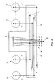
- Fig. 2 shows a telescope system known from the state of the art, in particular a schematically represented prototype of the VLT (Merkle).
- the system is provided with four jointly directable telescopes T.
- Light beams 1 coming from the telescopes T are passed on via delay lines D and an optical system 3 to light beam combining means 4.
- the delay lines D are provided with translatably disposed mirrors 2 to compensate optical path length differences.
- the beam combining means 4 comprise a parabolic mirror 4 collecting the light beams on a detector 5.
- the optical system 3 is arranged for capturing and passing the respective light beams 1 coming from the telescopes T and delay lines D on to combining mirror 4.
- this system known from the state of the art comprises four translatably disposed mirror assemblies 6, provided with different types of mirrors.
- Each mirror assembly comprises a deformable mirror (not shown) for adjusting longitudinal exit pupil positions.
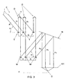
- Fig. 3 schematically shows an exemplary embodiment of a telescope system according to the invention.
- the system is provided with three tiltable telescopes T and delay lines D, and with an optical system M, N for the purpose of homothetic mapping of light beams 1 captured by the telescopes.
- the light beams enter the telescopes T with a first direction E relative to the earth's surface A.
- the optical system M, N is arranged for capturing respective light beams 1 coming from the telescopes T and passing them on, via respective exit pupils p u , to light beam combining means 101.
- the optical system represented in Fig. 3 is arranged for adjusting positions of the exit pupils p u during a movement of the telescopes T such that lateral distances between those exit pupils p u are homothetic to the lateral distances between the entrance pupils p i of the telescopes T.
- the optical system is provided with three pupil compensating mirrors M which, during use, individually reflect the respective light beams 1 coming from the three telescopes T.
- the three compensating mirrors M are designed to perform substantially the same movement as the telescopes T.
- the telescopes T are disposed around horizontal axes, so as to be tiltable relative to the surface of the earth. Therefore, the compensating mirrors M are also arranged so as to be tiltable relative to the earth's surface.
- each telescope T and each respective compensating mirror M is disposed on a substantially fixed position, at least non-translatable relative to the earth's surface.
- the earth's surface is schematically drawn in a broken line A.
- the set-up of the compensating mirrors M is homothetic to the set-up of the respective telescopes T.
- the set-up of the compensating mirrors M is a scaled copy of the set-up of the telescopes T.
- Fig. 3 is a schematic representation, in which the telescopes T and compensating mirrors M happen to be drawn in equispaced relation to each other.
- optical path length differences can be corrected through the position of the compensating mirrors M, without the use of delay lines.
- the telescopes T will be disposed at far greater distances relatively to each other.
- the delay lines D are to compensate relatively large optical path length differences.
- the delay lines D extend in vertical direction, while in practice, the delay lines D can, for instance, extend in horizontal direction, as represented in Fig. 2 .
- the exemplary embodiment is further provided with a directing mirror N for capturing light beams 1 coming from the compensating mirrors M and directing them to light beam combining means 101.
- the light beams 1 are depicted through the combining means 101 in a detection point D.
- the directing mirror N is both tiltable and translatable.
- the system represented in Fig. 3 is used in an advantageous manner in a method for combining light beams of telescopes T while using an optical system.
- the telescopes are jointly directed to, for instance, a far away light source.
- the light beams 1 coming from the telescopes 1 are separately captured by the compensating mirrors M and, via respective exit pupils p u , passed on to the light beams combining means 101.
- Such a position is represented in Fig. 3 .
- the compensating mirrors M are tilted such that these mirrors M have the light beams 1 exiting therefrom include the same angle ⁇ relative to the earth's surface A as the angle ⁇ relative to the earth's surface A at which the light beams 1 enter the telescopes:
- the compensating mirrors M adopt the same tilting position, at least mirrored relative to a vertical plane, as the telescopes T.
- the light beams coming from the compensating mirrors M are then simply captured by the directing mirror N and passed on to the light beam combining means 101.
- the longitudinal exit pupil positions are homothetic relative to those of the entrance pupils, which is also achieved in an easy manner due to the tilting position of the compensating mirrors M. Therefore, in the represented position, the exemplary embodiment effects that the light beams 1 are combined according to the principle of homothetic aperture mapping.
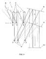
- FIG. 4 An interferometric observation can simply be carried out in a continuous manner during tilting of the telescopes T, by simply tilting the compensating mirrors M through the same angle so that the homothetic ratio of the entrance and exit pupils is maintained.
- Fig. 4 such tilting of the telescopes T and compensating mirrors M is schematically represented.
- the telescopes T are tilted through an angler ⁇ for capturing light beams 1 entering from a second direction F.
- the path of the light beams entering from the first direction E is drawn in chain-dotted lines.
- the compensating mirrors M are also tilted through the angle ⁇ in order that lateral and longitudinal pupil positions are still homothetic relative to the entrance pupils for the purpose of the aperture synthesis.
- the compensating mirrors M continuously adopt the same tilting positions as the respective telescopes T during tilting of these telescopes.
- the entrance and exit pupils remain homothetic relative to each other, so that the homothetic aperture synthesis can be carried out in a continuous manner.
- the directing mirror N is also tilted through a particular angle y, and translated over a particular distance Z for capturing the light beams coming from the compensating mirrors M and keeping them directed to the combining means 101.
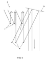
- Fig. 5 shows once more the final position of the system resulting from this tilting, however, without representation of the light beams entering from the first direction E with the associated first position of the directing mirror N.
- the system is provided with a control which is arranged for having each compensating mirror M perform, during use, substantially the same movement as the respective telescope T from which the compensating mirror M receives a light beam 1 and passes it on. Therefore, the aperture synthesis can be carried out in an automated manner.
- the control is also coupled to other parts of the telescope system, for instance the delay lines, the directing mirror, the light combining means (not shown), measuring means disposed in measuring point D, sensors and/or other parts of the system.
- a control can for instance comprise one or more computers and/or microcontrollers.
- the main telescopes T can for instance be positioned in different configurations relative to each other on earth and/or in space.
- the telescopes can, for instance, be aligned or not be aligned, in the same or not in the same plane, be placed at the same height and/or at different heights relative to the sea level.
- the compensating mirrors M can then be disposed in the same configuration.
- the telescopes T and compensating mirrors M can each be movably arranged in various ways, for instance tiltable around horizontal axes, rotatable about vertical axes relative to the earth's surface, and/or translatable.
- the optical system can be provided with one or more directing mirrors N.
- these can, for instance, be coupled to each other in order that the mirrors can perform identical directing movements.
- the directing mirror N can be disposed so as to be moveable and/or translatable in different directions.
- the light combining means can for instance be moveably disposed for capturing light beams coming from the optical system. This can for instance be desirable when the optical system is not provided with one or more directing mirrors for directing light to the light combining means.
- the telescope system can further be provided with various other, optical elements, for instance lenses, mirrors and the like for directing the light beams in a desired direction.
- optical elements for instance lenses, mirrors and the like for directing the light beams in a desired direction.
Landscapes
- Physics & Mathematics (AREA)
- Astronomy & Astrophysics (AREA)
- General Physics & Mathematics (AREA)
- Optics & Photonics (AREA)
- Telescopes (AREA)
- Lenses (AREA)
- Non-Portable Lighting Devices Or Systems Thereof (AREA)
Claims (19)
- Système de télescopes comprenant au moins deux télescopes (T) conjointement orientables ayant des pupilles d'entrée respectives (pi), le système de télescopes comprenant un système optique (M, N) disposé de manière à capter les rayons lumineux (1) respectifs provenant des télescopes (T) et à les transmettre, via des pupilles de sortie respectives (pu), à des moyens de combinaison de rayons lumineux, ledit système optique (M, N) étant agencé de manière à ajuster la position desdites pupilles de sortie (pu) au cours d'un mouvement - souhaité pour l'orientation - des télescopes (T) de telle sorte que les distances latérales entre ces pupilles de sortie (pu) soient homothétiques par rapport aux distances latérales entre les pupilles d'entrée (pi) des télescopes (T), le système optique comprenant au moins deux miroirs de compensation pupillaire (M) destinés à réfléchir les rayons lumineux (1) en provenance des au moins deux télescopes (T), caractérisé en ce que les miroirs de compensation (M) sont agencés de manière à exécuter sensiblement les mêmes mouvements que les télescopes (T).
- Système de télescopes selon la revendication 1, dans lequel les télescopes (T) et lesdits au moins deux miroirs de compensation sont agencés de manière à être inclinables autour d'axes horizontaux par rapport à la surface de la terre.
- Système de télescopes selon l'une quelconque des revendications précédentes, dans lequel les télescopes (T) et les au moins deux miroirs de compensation (M) sont agencés de manière à être mobiles en rotation autour d'axes verticaux par rapport à la surface de la terre.
- Système de télescopes selon au moins la revendication 1, dans lequel le système est équipé d'un dispositif d'asservissement agencé de manière à ce que chaque miroir de compensation (M), au moins pendant l'utilisation, exécute le même mouvement que le télescope (T) respectif en provenance duquel ce miroir de compensation (M) reçoit un rayon lumineux et le transmet.
- Système de télescopes selon l'une quelconque des revendications précédentes, dans lequel les télescopes (T) et chaque miroir de compensation (M) respectif sont agencés dans une position sensiblement fixe par rapport à la surface de la terre.
- Système de télescopes selon l'une quelconque des revendications précédentes, dans lequel lesdits moyens de combinaison de rayons lumineux sont mobiles afin de capter les rayons lumineux provenant dudit système optique.
- Système de télescopes selon au moins la revendication 1, dans lequel le système optique comprend au moins un miroir d'orientation (N) destiné à capter les rayons lumineux provenant des miroirs de compensation (M) et à les diriger vers les moyens de combinaison de rayons lumineux.
- Système de télescopes selon au moins les revendications 2 et 7, dans lequel le miroir d'orientation (N) est inclinable.
- Système de télescopes selon la revendication 8, dans lequel le miroir d'orientation (N) est également mobile en translation.
- Système de télescopes selon l'une quelconque des revendications précédentes, dans lequel la disposition des miroirs de compensation (M) est homothétique par rapport à la disposition des télescopes (T) respectifs.
- Système de télescopes selon l'une quelconque des revendications précédentes, dans lequel le système comprend également des lignes à retard (D) destinées à compenser les différences de chemin optique entre lesdits rayons lumineux.
- Système de télescopes selon la revendication 11, dans lequel lesdites lignes de retard (D) sont disposées entre les télescopes (T) et le système optique (M, N).
- Système de télescopes selon l'une quelconque des revendications précédentes, dans lequel lesdits miroirs de compensation (M) sont agencés de manière à transmettre les rayons lumineux provenant des télescopes (T) avec le même angle (α) par rapport à la surface de la terre que l'angle avec lequel les rayons lumineux sont captés, pendant l'utilisation, par les télescopes (T).
- Système de télescopes selon l'une quelconque des revendications précédentes, dans lequel le système est agencé sur terre.
- Système de télescopes selon au moins la revendication 1, dans lequel le système est agencé sensiblement hors de l'atmosphère terrestre, par exemple sur la lune ou dans l'espace.
- Procédé de combinaison de rayons lumineux provenant d'au moins deux télescopes (T) utilisant un système optique, dans lequel les au moins deux télescopes (T) comprennent des pupilles d'entrée respectives (pi), ledit système optique (M, N) comprenant au moins deux miroirs de compensation pupillaire (M), le procédé comprenant au moins les étapes suivantes :- les télescopes (T) sont conjointement dirigés vers, par exemple, une source lumineuse lointaine ; et- les rayons lumineux (1) provenant des télescopes (T) sont captés par les miroirs de compensation (M) et transmis, via des pupilles de sortie respectives (pu), aux moyens de combinaison de rayons lumineux,caractérisé en ce que les miroirs de compensation (M) exécutent sensiblement les mêmes mouvements que les télescopes respectifs, de manière à ce que les distances latérales entre lesdites pupilles de sortie (pu) soient homothétiques par rapport aux distances latérales entre lesdites pupilles d'entrée (pi) des télescopes (T).
- Procédé selon la revendication 16, dans lequel les rayons lumineux provenant des miroirs de compensation (M) sont captés par un miroir d'orientation (N) et sont transmis aux moyens de combinaison de rayons lumineux.
- Procédé selon la revendication 16 ou la revendication 17, dans lequel les télescopes (T) et les miroirs de compensation (M) sont inclinés sensiblement continuellement selon sensiblement les mêmes angles par rapport à la surface de la terre.
- Procédé selon au moins la revendication 16, dans lequel lesdits miroirs de compensation (M) adoptent continuellement les mêmes positions et la même configuration réciproque que les télescopes (T) respectifs.
Applications Claiming Priority (3)
| Application Number | Priority Date | Filing Date | Title |
|---|---|---|---|
| NL1022016 | 2002-11-28 | ||
| NL1022016A NL1022016C2 (nl) | 2002-11-28 | 2002-11-28 | Telescoopsysteem, alsmede een werkwijze voor het combineren van lichtbundels. |
| PCT/NL2003/000846 WO2004049033A1 (fr) | 2002-11-28 | 2003-11-28 | Systeme telescopique, et procede de combinaison de faisceaux de lumiere |
Publications (2)
| Publication Number | Publication Date |
|---|---|
| EP1565778A1 EP1565778A1 (fr) | 2005-08-24 |
| EP1565778B1 true EP1565778B1 (fr) | 2011-04-06 |
Family
ID=32389647
Family Applications (1)
| Application Number | Title | Priority Date | Filing Date |
|---|---|---|---|
| EP03779040A Expired - Lifetime EP1565778B1 (fr) | 2002-11-28 | 2003-11-28 | Systeme telescopique, et procede de combinaison de faisceaux de lumiere |
Country Status (6)
| Country | Link |
|---|---|
| EP (1) | EP1565778B1 (fr) |
| AT (1) | ATE504857T1 (fr) |
| AU (1) | AU2003289674A1 (fr) |
| DE (1) | DE60336675D1 (fr) |
| NL (1) | NL1022016C2 (fr) |
| WO (1) | WO2004049033A1 (fr) |
Families Citing this family (4)
| Publication number | Priority date | Publication date | Assignee | Title |
|---|---|---|---|---|
| US7504609B2 (en) | 2007-02-07 | 2009-03-17 | Raytheon Company | Phased-array light telescope |
| US8477419B1 (en) | 2010-12-31 | 2013-07-02 | Celestron, Llc | System and method for automatically aligning a telescope without requiring user intervention |
| US8401307B1 (en) | 2010-12-31 | 2013-03-19 | Celestron, Llc | Determining celestial coordinates for an image |
| US11181606B1 (en) | 2017-03-13 | 2021-11-23 | Celestron Acquisition, Llc | Pointing system for manual telescope |
Family Cites Families (3)
| Publication number | Priority date | Publication date | Assignee | Title |
|---|---|---|---|---|
| US4953964A (en) * | 1988-10-24 | 1990-09-04 | United Technologies Corporation | Phased array telescope |
| US4950063A (en) * | 1989-02-28 | 1990-08-21 | The United States Of America As Represented By The Secretary Of The Air Force | Automatic compensation of optical path for gimbaled phased array telescope |
| US5113284A (en) * | 1991-02-07 | 1992-05-12 | Talandic Research Corporation | Phased array optical telescope |
-
2002
- 2002-11-28 NL NL1022016A patent/NL1022016C2/nl not_active IP Right Cessation
-
2003
- 2003-11-28 AU AU2003289674A patent/AU2003289674A1/en not_active Abandoned
- 2003-11-28 DE DE60336675T patent/DE60336675D1/de not_active Expired - Lifetime
- 2003-11-28 EP EP03779040A patent/EP1565778B1/fr not_active Expired - Lifetime
- 2003-11-28 AT AT03779040T patent/ATE504857T1/de not_active IP Right Cessation
- 2003-11-28 WO PCT/NL2003/000846 patent/WO2004049033A1/fr not_active Ceased
Also Published As
| Publication number | Publication date |
|---|---|
| WO2004049033A1 (fr) | 2004-06-10 |
| EP1565778A1 (fr) | 2005-08-24 |
| NL1022016C2 (nl) | 2004-06-07 |
| DE60336675D1 (de) | 2011-05-19 |
| ATE504857T1 (de) | 2011-04-15 |
| AU2003289674A1 (en) | 2004-06-18 |
Similar Documents
| Publication | Publication Date | Title |
|---|---|---|
| US5561544A (en) | Laser scanning system with reflecting optics | |
| US4993818A (en) | Continuous zoom all-reflective optical system | |
| US4404592A (en) | Video imagery device, especially for a homing unit | |
| US5229889A (en) | Simple adaptive optical system | |
| US5034618A (en) | Method for aligning an articulated beam delivery device, such as a robot | |
| US9300851B2 (en) | Method and system for compensating optical aberrations in a telescope | |
| US4390253A (en) | Pitch and roll motion optical system for wide angle display | |
| US4266847A (en) | Apparatus for line-scanning of large image fields | |
| EP1565778B1 (fr) | Systeme telescopique, et procede de combinaison de faisceaux de lumiere | |
| US4475039A (en) | Infrared viewing apparatus | |
| US4953964A (en) | Phased array telescope | |
| US3558212A (en) | Gyroscopically stabilized optical systems | |
| JP2598528B2 (ja) | 連続可変焦点全反射光学装置 | |
| Bonaglia et al. | MORFEO/MAORY low-order and reference WFS module preliminary design | |
| EP0063425A1 (fr) | Lentille de projection de longueur focale variable utilisée pour des rétro-projecteurs | |
| US6587265B1 (en) | Prime focus unit | |
| US3261260A (en) | Vibration compensated optical viewing system | |
| Sturmann et al. | Infrared beam combination at the CHARA array | |
| US20050007660A1 (en) | Optical microscope comprising a displaceable objective | |
| Dierickx et al. | The optics of the OWL 100-m adaptive telescope | |
| EP1373968B1 (fr) | Separateur de faisceau | |
| Simoes et al. | Final design of the GTC laser guide star wavefront sensor | |
| EP0123627B1 (fr) | Dispositif de stabilisation d'image pour un périscope de sous-marin | |
| Manuel et al. | Opposed port alignment system (OPAS): a commercial astronomical telescope modified for viewing the interior of the NIF target chamber | |
| Arcidiacono et al. | The opto-mechanical alignment procedure of the VLT Survey Telescope |
Legal Events
| Date | Code | Title | Description |
|---|---|---|---|
| PUAI | Public reference made under article 153(3) epc to a published international application that has entered the european phase |
Free format text: ORIGINAL CODE: 0009012 |
|
| 17P | Request for examination filed |
Effective date: 20050527 |
|
| AK | Designated contracting states |
Kind code of ref document: A1 Designated state(s): AT BE BG CH CY CZ DE DK EE ES FI FR GB GR HU IE IT LI LU MC NL PT RO SE SI SK |
|
| AX | Request for extension of the european patent |
Extension state: AL LT LV MK |
|
| DAX | Request for extension of the european patent (deleted) | ||
| GRAP | Despatch of communication of intention to grant a patent |
Free format text: ORIGINAL CODE: EPIDOSNIGR1 |
|
| GRAS | Grant fee paid |
Free format text: ORIGINAL CODE: EPIDOSNIGR3 |
|
| GRAA | (expected) grant |
Free format text: ORIGINAL CODE: 0009210 |
|
| AK | Designated contracting states |
Kind code of ref document: B1 Designated state(s): AT BE BG CH CY CZ DE DK EE ES FI FR GB GR HU IE IT LI LU MC NL PT RO SE SI SK |
|
| REG | Reference to a national code |
Ref country code: GB Ref legal event code: FG4D |
|
| REG | Reference to a national code |
Ref country code: CH Ref legal event code: EP |
|
| REG | Reference to a national code |
Ref country code: IE Ref legal event code: FG4D |
|
| REF | Corresponds to: |
Ref document number: 60336675 Country of ref document: DE Date of ref document: 20110519 Kind code of ref document: P |
|
| REG | Reference to a national code |
Ref country code: DE Ref legal event code: R096 Ref document number: 60336675 Country of ref document: DE Effective date: 20110519 |
|
| REG | Reference to a national code |
Ref country code: NL Ref legal event code: VDEP Effective date: 20110406 |
|
| PG25 | Lapsed in a contracting state [announced via postgrant information from national office to epo] |
Ref country code: SI Free format text: LAPSE BECAUSE OF FAILURE TO SUBMIT A TRANSLATION OF THE DESCRIPTION OR TO PAY THE FEE WITHIN THE PRESCRIBED TIME-LIMIT Effective date: 20110406 |
|
| PG25 | Lapsed in a contracting state [announced via postgrant information from national office to epo] |
Ref country code: SE Free format text: LAPSE BECAUSE OF FAILURE TO SUBMIT A TRANSLATION OF THE DESCRIPTION OR TO PAY THE FEE WITHIN THE PRESCRIBED TIME-LIMIT Effective date: 20110406 Ref country code: PT Free format text: LAPSE BECAUSE OF FAILURE TO SUBMIT A TRANSLATION OF THE DESCRIPTION OR TO PAY THE FEE WITHIN THE PRESCRIBED TIME-LIMIT Effective date: 20110808 |
|
| PG25 | Lapsed in a contracting state [announced via postgrant information from national office to epo] |
Ref country code: CY Free format text: LAPSE BECAUSE OF FAILURE TO SUBMIT A TRANSLATION OF THE DESCRIPTION OR TO PAY THE FEE WITHIN THE PRESCRIBED TIME-LIMIT Effective date: 20110406 Ref country code: GR Free format text: LAPSE BECAUSE OF FAILURE TO SUBMIT A TRANSLATION OF THE DESCRIPTION OR TO PAY THE FEE WITHIN THE PRESCRIBED TIME-LIMIT Effective date: 20110707 Ref country code: ES Free format text: LAPSE BECAUSE OF FAILURE TO SUBMIT A TRANSLATION OF THE DESCRIPTION OR TO PAY THE FEE WITHIN THE PRESCRIBED TIME-LIMIT Effective date: 20110717 Ref country code: AT Free format text: LAPSE BECAUSE OF FAILURE TO SUBMIT A TRANSLATION OF THE DESCRIPTION OR TO PAY THE FEE WITHIN THE PRESCRIBED TIME-LIMIT Effective date: 20110406 Ref country code: BE Free format text: LAPSE BECAUSE OF FAILURE TO SUBMIT A TRANSLATION OF THE DESCRIPTION OR TO PAY THE FEE WITHIN THE PRESCRIBED TIME-LIMIT Effective date: 20110406 Ref country code: FI Free format text: LAPSE BECAUSE OF FAILURE TO SUBMIT A TRANSLATION OF THE DESCRIPTION OR TO PAY THE FEE WITHIN THE PRESCRIBED TIME-LIMIT Effective date: 20110406 |
|
| PG25 | Lapsed in a contracting state [announced via postgrant information from national office to epo] |
Ref country code: NL Free format text: LAPSE BECAUSE OF FAILURE TO SUBMIT A TRANSLATION OF THE DESCRIPTION OR TO PAY THE FEE WITHIN THE PRESCRIBED TIME-LIMIT Effective date: 20110406 |
|
| PG25 | Lapsed in a contracting state [announced via postgrant information from national office to epo] |
Ref country code: CZ Free format text: LAPSE BECAUSE OF FAILURE TO SUBMIT A TRANSLATION OF THE DESCRIPTION OR TO PAY THE FEE WITHIN THE PRESCRIBED TIME-LIMIT Effective date: 20110406 Ref country code: EE Free format text: LAPSE BECAUSE OF FAILURE TO SUBMIT A TRANSLATION OF THE DESCRIPTION OR TO PAY THE FEE WITHIN THE PRESCRIBED TIME-LIMIT Effective date: 20110406 |
|
| PLBE | No opposition filed within time limit |
Free format text: ORIGINAL CODE: 0009261 |
|
| STAA | Information on the status of an ep patent application or granted ep patent |
Free format text: STATUS: NO OPPOSITION FILED WITHIN TIME LIMIT |
|
| PG25 | Lapsed in a contracting state [announced via postgrant information from national office to epo] |
Ref country code: RO Free format text: LAPSE BECAUSE OF FAILURE TO SUBMIT A TRANSLATION OF THE DESCRIPTION OR TO PAY THE FEE WITHIN THE PRESCRIBED TIME-LIMIT Effective date: 20110406 Ref country code: SK Free format text: LAPSE BECAUSE OF FAILURE TO SUBMIT A TRANSLATION OF THE DESCRIPTION OR TO PAY THE FEE WITHIN THE PRESCRIBED TIME-LIMIT Effective date: 20110406 Ref country code: DK Free format text: LAPSE BECAUSE OF FAILURE TO SUBMIT A TRANSLATION OF THE DESCRIPTION OR TO PAY THE FEE WITHIN THE PRESCRIBED TIME-LIMIT Effective date: 20110406 |
|
| 26N | No opposition filed |
Effective date: 20120110 |
|
| REG | Reference to a national code |
Ref country code: DE Ref legal event code: R097 Ref document number: 60336675 Country of ref document: DE Effective date: 20120110 |
|
| PG25 | Lapsed in a contracting state [announced via postgrant information from national office to epo] |
Ref country code: MC Free format text: LAPSE BECAUSE OF NON-PAYMENT OF DUE FEES Effective date: 20111130 |
|
| REG | Reference to a national code |
Ref country code: CH Ref legal event code: PL |
|
| GBPC | Gb: european patent ceased through non-payment of renewal fee |
Effective date: 20111128 |
|
| PG25 | Lapsed in a contracting state [announced via postgrant information from national office to epo] |
Ref country code: LI Free format text: LAPSE BECAUSE OF NON-PAYMENT OF DUE FEES Effective date: 20111130 Ref country code: CH Free format text: LAPSE BECAUSE OF NON-PAYMENT OF DUE FEES Effective date: 20111130 |
|
| REG | Reference to a national code |
Ref country code: FR Ref legal event code: ST Effective date: 20120731 |
|
| REG | Reference to a national code |
Ref country code: IE Ref legal event code: MM4A |
|
| REG | Reference to a national code |
Ref country code: DE Ref legal event code: R119 Ref document number: 60336675 Country of ref document: DE Effective date: 20120601 |
|
| PG25 | Lapsed in a contracting state [announced via postgrant information from national office to epo] |
Ref country code: GB Free format text: LAPSE BECAUSE OF NON-PAYMENT OF DUE FEES Effective date: 20111128 Ref country code: IE Free format text: LAPSE BECAUSE OF NON-PAYMENT OF DUE FEES Effective date: 20111128 |
|
| PG25 | Lapsed in a contracting state [announced via postgrant information from national office to epo] |
Ref country code: FR Free format text: LAPSE BECAUSE OF NON-PAYMENT OF DUE FEES Effective date: 20111130 |
|
| PG25 | Lapsed in a contracting state [announced via postgrant information from national office to epo] |
Ref country code: LU Free format text: LAPSE BECAUSE OF NON-PAYMENT OF DUE FEES Effective date: 20111128 |
|
| PG25 | Lapsed in a contracting state [announced via postgrant information from national office to epo] |
Ref country code: DE Free format text: LAPSE BECAUSE OF NON-PAYMENT OF DUE FEES Effective date: 20120601 Ref country code: BG Free format text: LAPSE BECAUSE OF FAILURE TO SUBMIT A TRANSLATION OF THE DESCRIPTION OR TO PAY THE FEE WITHIN THE PRESCRIBED TIME-LIMIT Effective date: 20110706 |
|
| PG25 | Lapsed in a contracting state [announced via postgrant information from national office to epo] |
Ref country code: HU Free format text: LAPSE BECAUSE OF FAILURE TO SUBMIT A TRANSLATION OF THE DESCRIPTION OR TO PAY THE FEE WITHIN THE PRESCRIBED TIME-LIMIT Effective date: 20110406 |
|
| PG25 | Lapsed in a contracting state [announced via postgrant information from national office to epo] |
Ref country code: IT Free format text: LAPSE BECAUSE OF FAILURE TO SUBMIT A TRANSLATION OF THE DESCRIPTION OR TO PAY THE FEE WITHIN THE PRESCRIBED TIME-LIMIT Effective date: 20110406 |