EP0063425A1 - Lentille de projection de longueur focale variable utilisée pour des rétro-projecteurs - Google Patents
Lentille de projection de longueur focale variable utilisée pour des rétro-projecteurs Download PDFInfo
- Publication number
- EP0063425A1 EP0063425A1 EP82301637A EP82301637A EP0063425A1 EP 0063425 A1 EP0063425 A1 EP 0063425A1 EP 82301637 A EP82301637 A EP 82301637A EP 82301637 A EP82301637 A EP 82301637A EP 0063425 A1 EP0063425 A1 EP 0063425A1
- Authority
- EP
- European Patent Office
- Prior art keywords
- lens
- lens elements
- column
- focal length
- given
- Prior art date
- Legal status (The legal status is an assumption and is not a legal conclusion. Google has not performed a legal analysis and makes no representation as to the accuracy of the status listed.)
- Granted
Links
Images
Classifications
-
- G—PHYSICS
- G03—PHOTOGRAPHY; CINEMATOGRAPHY; ANALOGOUS TECHNIQUES USING WAVES OTHER THAN OPTICAL WAVES; ELECTROGRAPHY; HOLOGRAPHY
- G03B—APPARATUS OR ARRANGEMENTS FOR TAKING PHOTOGRAPHS OR FOR PROJECTING OR VIEWING THEM; APPARATUS OR ARRANGEMENTS EMPLOYING ANALOGOUS TECHNIQUES USING WAVES OTHER THAN OPTICAL WAVES; ACCESSORIES THEREFOR
- G03B21/00—Projectors or projection-type viewers; Accessories therefor
- G03B21/132—Overhead projectors, i.e. capable of projecting hand-writing or drawing during action
-
- G—PHYSICS
- G03—PHOTOGRAPHY; CINEMATOGRAPHY; ANALOGOUS TECHNIQUES USING WAVES OTHER THAN OPTICAL WAVES; ELECTROGRAPHY; HOLOGRAPHY
- G03B—APPARATUS OR ARRANGEMENTS FOR TAKING PHOTOGRAPHS OR FOR PROJECTING OR VIEWING THEM; APPARATUS OR ARRANGEMENTS EMPLOYING ANALOGOUS TECHNIQUES USING WAVES OTHER THAN OPTICAL WAVES; ACCESSORIES THEREFOR
- G03B21/00—Projectors or projection-type viewers; Accessories therefor
Definitions
- This invention relates to an overhead projection lens to vary the focal length and magnification of the lens to adjust the'image size to the screen without a change in the object-to-image distance.
- Overhead Projection lenses have taken many forms, and the most conventional form in use today is a two-element projection lens utilizing two positive spaced meniscus lenses, one to direct light toward a reflector and the other to receive light from the reflector to project an image from a stage to the screen. The image is focused by movement of the head toward and away from the stage upon which the transparency is placed.
- Other projection systems have utilized two or more lenses spaced on the same side of the reflector, or one on each side of a reflector but, movement of the lenses relative'to one another, or together usually provided only a means for focussing the image on the distant screen, see for example, U.S.A. patent No. 3,408,135, issued October 29, 1968, assigned to the assignee of this application. In these systems, variations in the stage-to-screen distance afford changes in magnification.
- a lens constructed according to the present invention is movable vertically with respect to the stage to permit a focusing of the image on the remote screen, and the rear lens element, the element closest to the screen, is movable to effectively change the equivalent focal length and the magnification factor of the lens to match the size of the projected image with the screen without a change in the position of the projector.
- the present invention is directed to a variable magnification projection lens comprising four elements which, by the relative movement of one element, will afford a change in the effective focal length.
- the lens system has good image quality over its entire focal length range. Hence, the image magnification can be varied for a fixed object-to-image distance (OID).
- the entire projection lens can be moved relative to the object to afford focussing of the projected image.
- the lens comprises a first negative meniscus lens airspaced from a positive meniscus lens which is airspaced and generally on the other side of an inexpensive folding mirror from a second positive lens which in turn is airspaced from a-movable negative lens.
- Two embodiments of a-lens corresponding to the present invention are described herein affording a change in the magnification of the lens by a factor of 1.4X to 1.5X at a given object-to-image distance.
- the change in the effective focal length and the resultant magnification by the movement of a single lens element permits the image of the transparency to fill a given screen size without moving the projector.
- the lens is designed for use on projectors with head focusing and lamp-position adjustment. The use of only four lens elements with inexpensive glass makes this system economical for overhead projector application.
- the lens system of the present invention permits the focal length ' to be variable throughout the range of movement of the lens affording a continuous change in the magnification by about a factor of 1.4 to 1.5, without changing the object-to-image distance, i.e. stage-to-screen distance.
- the lens system of the present invention allows a given screen size to be filled at various projector- to-screen distances.
- the lens system of the present invention is designed such that movement of the element closest to the screen adjusts the focal length and resultant magnification. Movement of the entire lens system with respect to the stage focusses the image on the screen similar to a fixed focal length system. Movement of the lamp to move the position of the image of the lamp in the projection head, maintains an effective stop position about half way between the four lenses of the lens assembly. This lamp movement during focusing assures a good contrast image and no vignetting of light in the system.
- the folding mirror positioned between the positive lenses of the lens assembly may pivot about the optic axis to afford a movement of the projected image and in so moving the mirror, the front lens group pivots at twice the angular rate of pivotal movement of the folding mirror. Such a pivoting movement can change the projection angle up to 30 degrees from the horizontal and still maintain good image quality.
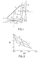
- FIG. 1 there is illustrated a compact variable focus lens assembly for use in an overhead projector which permits a folding of the projected light from the vertical path to the horizontal path to direct the same toward a remote screen.
- the stage and screen are not illustrated, and the lens assembly of the present invention is preferably mounted for movement along the optic axis toward and away from the stage, and the mirror and lens elements forming the rear group are movable to afford a tilt capability of the image to move the same up and down on the screen in the manner well known in the art as an "articulating" arrangement wherein the front lens grouping pivots at twice the angular rate of pivotal movement of the mirror. '
- the lens illustrated in Figure 1 comprises a first negative meniscus lens 1 which is airspaced S 1 from a positive meniscus lens 2 which is convex concave,'a reflector or folding mirror 5 and a second positive lens 3 which is a biconvex or double convex lens which is spaced, S 3 from a movable negative lens 4 which is a double concave lens.
- the respective lens elements are recited together with the corresponding refractive indices N for the D line of the spectrum, the corresponding dispersive indices V, are given for each lens and the radii of curvature R of each surface of each lens element is given.
- the respective surfaces are numbered in sequence and indicated by the subscript in the same order as the lens elements are numbered and are consecutively numbered from the stage toward the screen with plus and minus values of R indicating surfaces which are respectively convex and concave to radiation entering the front lens element of the system (the element closest to the stage).
- the axial thickness T of the respective lens elements and the air spaces between the lens elements are also recited with the respective lens elements thickness being identified for each lens by the corresponding subscript and the air spaces S between the lens elements being also identified by subscripts numbered in sequence in the same order as the lens elements.
- the quantities of the radii, thickness and spacing are expressed in millimeters.
- the lens system shown in the table below has a variable focal length between 277.3 mm and 365.4 mm and the length along the optic axis varies between 124.0 mm and 163.0 mm.
- the lens 1 has an equivalent focal length of -645.31 mm
- lens 2 has an equivalent focal length of 278.76 mm
- element 3 has an equivalent focal length of 220.48 mm
- element 4 has an equivalent focal length of -274.09.
- the nominal diameters for the lenses are as follows: Lens 1, 105.0 mm; lenses 2 and 3, 90 mm; and lens 4 having a diameter of 110.0 mm.
- the lenses are designed and sized to project a full A4 size stage (285 x 285 mm).
- the lens of Table 1 provides variable magnifications at various distances from the screen, and the table below, Table 2, provides a representative sample of the magnifications at various focal lengths for fixed stage-to-screen distances.
- FIG. 2 there is illustrated a graph showing a set of curves which graphically illustrate the extent of change of the focal length, magnification, back focal distance and stage-to-screen distances for the lens of Figure 1 and Table 1.
- the chart plots the magnification M between 3X and 8X on the vertical axis with the back focal distance BF plotted on the horizontal axis between 300 and 450 mm.
- Line 6 illustrates a fixed focal length of 277.3 mm wherein S 3 equals 40 mm, line 7 corresponds to the fixed focal length of 323.3 mm, wherein S 3 equals 15 mm; and line 8 indicates the fixed focal length of 356.4 mm, wherein S 3 equals lmm.
- the horizontally extending curved lines correspond to fixed stage-to-screen distances wherein line 9 equals a stage-to-screen distance (OID) of 2.158 meters, line 10 equals a stage-to-screen distance (OID) of 2.428 meters, and line 11 illustrates a fixed stage-to-screen distance (OID) of 2.8 meters.
- a second embodiment of a lens assembly corresponding to the present invention is indicated in Table 3:
- the lens assembly of Table 3 has a focal length varying between 276.0 mm and 356.8 mm, and the length along the optic axis of the system varies between 134.5 mm and 158.5 mm.
- the equivalent focal length of lens 1 is -612.52 mm
- of lens 2 is 260.15 mm
- of lens 3 is 175.10 mm
- the nominal diameter of the lenses are respectively for lens 1, 105.0 mm; for lenses 2 and 3, 90.0 mm; and for lens 4, 110.0 mm.
- the lens elements are numbered consecutively from the stage toward the screen as in Table 1 with the subscripts for the respective surfaces being also numbered consecutively in the same direction and given in millimeters with the thicknesses T given in millimeters for each individual lens, and the spacing S between the lenses being given in millimeters.
- Table 4 shows the magnifications of a lens according to Table 3 at various focal lengths for fixed stage-to-screen distances.
- This table shows a 1.4 to 1.5 change in magnification at any stage-to-screen distance. This is arrived at by taking the ratio of the absolute magnifications at the limiting focal length values of the lens system at any stage-to-screen distance.
Landscapes
- Physics & Mathematics (AREA)
- General Physics & Mathematics (AREA)
- Lenses (AREA)
- Overhead Projectors And Projection Screens (AREA)
Applications Claiming Priority (2)
| Application Number | Priority Date | Filing Date | Title |
|---|---|---|---|
| US06/254,947 US4380374A (en) | 1981-04-16 | 1981-04-16 | Variable focal length projection lens for use on overhead projectors |
| US254947 | 2002-09-25 |
Publications (2)
| Publication Number | Publication Date |
|---|---|
| EP0063425A1 true EP0063425A1 (fr) | 1982-10-27 |
| EP0063425B1 EP0063425B1 (fr) | 1985-07-03 |
Family
ID=22966203
Family Applications (1)
| Application Number | Title | Priority Date | Filing Date |
|---|---|---|---|
| EP82301637A Expired EP0063425B1 (fr) | 1981-04-16 | 1982-03-29 | Lentille de projection de longueur focale variable utilisée pour des rétro-projecteurs |
Country Status (9)
| Country | Link |
|---|---|
| US (1) | US4380374A (fr) |
| EP (1) | EP0063425B1 (fr) |
| JP (2) | JPS57181517A (fr) |
| AU (1) | AU545307B2 (fr) |
| BR (1) | BR8202173A (fr) |
| CA (1) | CA1178834A (fr) |
| DE (1) | DE3264517D1 (fr) |
| IE (1) | IE52987B1 (fr) |
| ZA (1) | ZA822579B (fr) |
Cited By (2)
| Publication number | Priority date | Publication date | Assignee | Title |
|---|---|---|---|---|
| GB2182784A (en) * | 1985-08-14 | 1987-05-20 | Asahi Optical Co Ltd | Two group zoom lens for use in copying |
| EP2218580A1 (fr) | 2009-02-17 | 2010-08-18 | E. I. du Pont de Nemours and Company | Méthode et appareil pour la préparation d'une forme d'impression à partir d'énergie de vibration |
Families Citing this family (8)
| Publication number | Priority date | Publication date | Assignee | Title |
|---|---|---|---|---|
| GB2168502A (en) * | 1984-12-14 | 1986-06-18 | Philips Electronic Associated | Projection lens system |
| GB2168501A (en) * | 1984-12-14 | 1986-06-18 | Philips Electronic Associated | Projection lens system |
| US4744641A (en) * | 1987-06-01 | 1988-05-17 | Minnesota Mining And Manufacturing Company | Telephoto lens assembly for overhead projector |
| JPH0671727B2 (ja) * | 1988-01-18 | 1994-09-14 | マツダ株式会社 | スライシングマシンおよびその制御方法 |
| DE19648620C2 (de) * | 1996-11-12 | 1998-10-29 | Mannesmann Ag | Beleuchtungssystem zur Beleuchtung eines einstellbaren Beleuchtungsfeldes |
| RU2655622C1 (ru) * | 2017-02-02 | 2018-05-29 | Открытое Акционерное общество "Ростовский оптико-механический завод" | Объектив |
| CN109491049B (zh) * | 2018-12-26 | 2023-08-29 | 歌尔光学科技有限公司 | 投影光学系统及具有其的增强现实眼镜 |
| CN114859515B (zh) * | 2022-05-23 | 2024-01-12 | 张家港中贺自动化科技有限公司 | 一种用于投影光刻的折反式物镜光学系统及投影光刻系统 |
Citations (3)
| Publication number | Priority date | Publication date | Assignee | Title |
|---|---|---|---|---|
| US3357775A (en) * | 1961-11-13 | 1967-12-12 | Minnesota Mining & Mfg | Projection objective affording variable magnification |
| GB1216581A (en) * | 1968-01-01 | 1970-12-23 | Omal Group Ltd | Improvements in overhead projectors |
| FR2273290A1 (fr) * | 1974-05-29 | 1975-12-26 | Lindaco Ltd |
Family Cites Families (4)
| Publication number | Priority date | Publication date | Assignee | Title |
|---|---|---|---|---|
| US3408135A (en) * | 1966-04-12 | 1968-10-29 | Minnesota Mining & Mfg | Projective objective having three elements plus an integral right angle prism |
| US4311366A (en) * | 1978-03-01 | 1982-01-19 | J. H. Dallmeyer Limited | Image focusing system |
| JPS5813887B2 (ja) * | 1979-06-20 | 1983-03-16 | 旭光学工業株式会社 | 複写変倍レンズ系 |
| US4350415A (en) * | 1980-09-02 | 1982-09-21 | Minnesota Mining & Manufacturing Company | Auxiliary lens system for overhead projectors |
-
1981
- 1981-04-16 US US06/254,947 patent/US4380374A/en not_active Expired - Fee Related
-
1982
- 1982-03-29 EP EP82301637A patent/EP0063425B1/fr not_active Expired
- 1982-03-29 DE DE8282301637T patent/DE3264517D1/de not_active Expired
- 1982-04-07 CA CA000400655A patent/CA1178834A/fr not_active Expired
- 1982-04-15 BR BR8202173A patent/BR8202173A/pt not_active IP Right Cessation
- 1982-04-15 JP JP57063212A patent/JPS57181517A/ja active Pending
- 1982-04-15 IE IE893/82A patent/IE52987B1/en not_active IP Right Cessation
- 1982-04-15 ZA ZA822579A patent/ZA822579B/xx unknown
- 1982-04-15 AU AU82655/82A patent/AU545307B2/en not_active Ceased
-
1990
- 1990-10-30 JP JP1990114009U patent/JPH0373909U/ja active Pending
Patent Citations (3)
| Publication number | Priority date | Publication date | Assignee | Title |
|---|---|---|---|---|
| US3357775A (en) * | 1961-11-13 | 1967-12-12 | Minnesota Mining & Mfg | Projection objective affording variable magnification |
| GB1216581A (en) * | 1968-01-01 | 1970-12-23 | Omal Group Ltd | Improvements in overhead projectors |
| FR2273290A1 (fr) * | 1974-05-29 | 1975-12-26 | Lindaco Ltd |
Cited By (3)
| Publication number | Priority date | Publication date | Assignee | Title |
|---|---|---|---|---|
| GB2182784A (en) * | 1985-08-14 | 1987-05-20 | Asahi Optical Co Ltd | Two group zoom lens for use in copying |
| GB2182784B (en) * | 1985-08-14 | 1989-11-01 | Asahi Optical Co Ltd | Two group zoom lens for use in copying. |
| EP2218580A1 (fr) | 2009-02-17 | 2010-08-18 | E. I. du Pont de Nemours and Company | Méthode et appareil pour la préparation d'une forme d'impression à partir d'énergie de vibration |
Also Published As
| Publication number | Publication date |
|---|---|
| US4380374A (en) | 1983-04-19 |
| EP0063425B1 (fr) | 1985-07-03 |
| IE52987B1 (en) | 1988-04-27 |
| JPH0373909U (fr) | 1991-07-25 |
| DE3264517D1 (en) | 1985-08-08 |
| AU545307B2 (en) | 1985-07-11 |
| BR8202173A (pt) | 1983-03-29 |
| ZA822579B (en) | 1983-04-27 |
| IE820893L (en) | 1982-10-16 |
| JPS57181517A (en) | 1982-11-09 |
| CA1178834A (fr) | 1984-12-04 |
| AU8265582A (en) | 1982-10-21 |
Similar Documents
| Publication | Publication Date | Title |
|---|---|---|
| US4249793A (en) | Erect type zoom telescopic optical system | |
| US4848883A (en) | Telephoto zoom lens system having four lens groups | |
| JP2801293B2 (ja) | ズームレンズ | |
| JP3291746B2 (ja) | ズームレンズ系 | |
| US4874231A (en) | Zoom lens | |
| US4126386A (en) | Image stabilization system for continuous film scanning apparatus | |
| US4189211A (en) | Wide angle telecentric projection lens assembly | |
| EP0063425B1 (fr) | Lentille de projection de longueur focale variable utilisée pour des rétro-projecteurs | |
| US4624555A (en) | Slit exposure projection device | |
| JPS6119010B2 (fr) | ||
| US6059721A (en) | Endoscope having variable magnification and focusing | |
| US5319495A (en) | Zoom lens | |
| US4560242A (en) | Variable magnification optical system | |
| JP2743440B2 (ja) | 有限共役距離ズームレンズ系 | |
| US4350415A (en) | Auxiliary lens system for overhead projectors | |
| US4278331A (en) | Photographic objective which prevents variation in angular field of view during focusing | |
| US3357775A (en) | Projection objective affording variable magnification | |
| US5731910A (en) | Optical system with variable image scale | |
| JPH077145B2 (ja) | 有限共役距離における変倍光学系 | |
| US4525042A (en) | Optical system of variable focal and back-focal length | |
| US4518227A (en) | Method of widening the angular field of a photographic objective lens | |
| US3222981A (en) | Two-element projection lens | |
| US4867555A (en) | Retrofocus lens for overhead projector | |
| JPH08227039A (ja) | ズームレンズ | |
| US4744641A (en) | Telephoto lens assembly for overhead projector |
Legal Events
| Date | Code | Title | Description |
|---|---|---|---|
| PUAI | Public reference made under article 153(3) epc to a published international application that has entered the european phase |
Free format text: ORIGINAL CODE: 0009012 |
|
| AK | Designated contracting states |
Designated state(s): DE FR GB IT SE |
|
| 17P | Request for examination filed |
Effective date: 19830421 |
|
| ITF | It: translation for a ep patent filed |
Owner name: BARZANO' E ZANARDO ROMA S.P.A. |
|
| GRAA | (expected) grant |
Free format text: ORIGINAL CODE: 0009210 |
|
| AK | Designated contracting states |
Designated state(s): DE FR GB IT SE |
|
| REF | Corresponds to: |
Ref document number: 3264517 Country of ref document: DE Date of ref document: 19850808 |
|
| ET | Fr: translation filed | ||
| PLBE | No opposition filed within time limit |
Free format text: ORIGINAL CODE: 0009261 |
|
| STAA | Information on the status of an ep patent application or granted ep patent |
Free format text: STATUS: NO OPPOSITION FILED WITHIN TIME LIMIT |
|
| 26N | No opposition filed | ||
| REG | Reference to a national code |
Ref country code: GB Ref legal event code: 732 |
|
| ITTA | It: last paid annual fee | ||
| PGFP | Annual fee paid to national office [announced via postgrant information from national office to epo] |
Ref country code: SE Payment date: 19911107 Year of fee payment: 11 |
|
| PGFP | Annual fee paid to national office [announced via postgrant information from national office to epo] |
Ref country code: FR Payment date: 19920227 Year of fee payment: 11 |
|
| PGFP | Annual fee paid to national office [announced via postgrant information from national office to epo] |
Ref country code: DE Payment date: 19920302 Year of fee payment: 11 |
|
| PGFP | Annual fee paid to national office [announced via postgrant information from national office to epo] |
Ref country code: GB Payment date: 19920306 Year of fee payment: 11 |
|
| PG25 | Lapsed in a contracting state [announced via postgrant information from national office to epo] |
Ref country code: GB Effective date: 19930329 |
|
| PG25 | Lapsed in a contracting state [announced via postgrant information from national office to epo] |
Ref country code: SE Effective date: 19930330 |
|
| GBPC | Gb: european patent ceased through non-payment of renewal fee |
Effective date: 19930329 |
|
| PG25 | Lapsed in a contracting state [announced via postgrant information from national office to epo] |
Ref country code: FR Effective date: 19931130 |
|
| PG25 | Lapsed in a contracting state [announced via postgrant information from national office to epo] |
Ref country code: DE Effective date: 19931201 |
|
| REG | Reference to a national code |
Ref country code: FR Ref legal event code: ST |
|
| EUG | Se: european patent has lapsed |
Ref document number: 82301637.3 Effective date: 19931008 |