EP1565101B1 - Method and apparatus for selecting regions of interest in optical imaging - Google Patents
Method and apparatus for selecting regions of interest in optical imaging Download PDFInfo
- Publication number
- EP1565101B1 EP1565101B1 EP03773382A EP03773382A EP1565101B1 EP 1565101 B1 EP1565101 B1 EP 1565101B1 EP 03773382 A EP03773382 A EP 03773382A EP 03773382 A EP03773382 A EP 03773382A EP 1565101 B1 EP1565101 B1 EP 1565101B1
- Authority
- EP
- European Patent Office
- Prior art keywords
- roi
- mammal
- optical imaging
- coordinates
- imaging system
- Prior art date
- Legal status (The legal status is an assumption and is not a legal conclusion. Google has not performed a legal analysis and makes no representation as to the accuracy of the status listed.)
- Expired - Lifetime
Links
Images
Classifications
-
- A—HUMAN NECESSITIES
- A61—MEDICAL OR VETERINARY SCIENCE; HYGIENE
- A61B—DIAGNOSIS; SURGERY; IDENTIFICATION
- A61B5/00—Measuring for diagnostic purposes; Identification of persons
- A61B5/0059—Measuring for diagnostic purposes; Identification of persons using light, e.g. diagnosis by transillumination, diascopy, fluorescence
-
- A—HUMAN NECESSITIES
- A61—MEDICAL OR VETERINARY SCIENCE; HYGIENE
- A61B—DIAGNOSIS; SURGERY; IDENTIFICATION
- A61B5/00—Measuring for diagnostic purposes; Identification of persons
- A61B5/70—Means for positioning the patient in relation to the detecting, measuring or recording means
- A61B5/704—Tables
-
- A—HUMAN NECESSITIES
- A61—MEDICAL OR VETERINARY SCIENCE; HYGIENE
- A61B—DIAGNOSIS; SURGERY; IDENTIFICATION
- A61B5/00—Measuring for diagnostic purposes; Identification of persons
- A61B5/05—Detecting, measuring or recording for diagnosis by means of electric currents or magnetic fields; Measuring using microwaves or radio waves
- A61B5/055—Detecting, measuring or recording for diagnosis by means of electric currents or magnetic fields; Measuring using microwaves or radio waves involving electronic [EMR] or nuclear [NMR] magnetic resonance, e.g. magnetic resonance imaging
-
- A—HUMAN NECESSITIES
- A61—MEDICAL OR VETERINARY SCIENCE; HYGIENE
- A61B—DIAGNOSIS; SURGERY; IDENTIFICATION
- A61B6/00—Apparatus or devices for radiation diagnosis; Apparatus or devices for radiation diagnosis combined with radiation therapy equipment
- A61B6/04—Positioning of patients; Tiltable beds or the like
Definitions
- the invention relates to the field of optical imaging and more specifically to the field of selecting regions of interest in a subject for optical imaging.
- Optical imaging has evolved to become a useful diagnostic tool.
- Various system designs have been developed to accommodate imaging of various parts of the human body.
- Hillman et al. Physical Med. Biol, 46 (2001)1117-1130
- Pogue et al. (Opt. Express 1 (1997) 391-403) describes a system for breast imaging.
- Optical imaging systems have also been developed for small mammals with a view of providing a research tool that can image changes in the physiology of the mammals and that can also provide information on the biodistribution molecules such as chromophores and fluorophores.
- An example of an optical imaging system for small mammals has been described in patent application WO 0137195.
- a suitable imaging tool should be able to reliably and reproducibly produce images of the same region of interest in a subject over time. In this respect accurate and reproducible positioning of the subject relative to the imaging optics is very important.
- optical imaging systems permit the repositioning of a subject in more or less the same position over several imaging sessions, they lack a positioning system that is reliable and precise. Thus there is a need for improved systems and methods for selecting regions of interest in a subject and reproducibly image the selected regions over time.
- the present invention provides a system and method for selecting regions of interest (ROIs) in a subject such as a mammal and for reproducibly positioning the subject to image the same ROIs over time.
- ROIs regions of interest
- a method for positioning a small mammal such as a mouse for optical imaging in which a digital image of the mammal is obtained and used to define a ROI by placing the mammal in the field of view of a camera.
- the ROI is then registered with an optical imaging system and the mammal is positioned relative to the imaging system in accordance with the coordinates of the ROI.
- the ROI is selected by determining the contour of the ROI on a computer displayed image of a surface comprising the ROI.
- a second digital image may be obtained to determine a plane at which the imaging system is focused for acquiring optical data when using an optical system in which light is propagated through air and wherein the optical signal is collected using lenses.
- fiducial marks are inscribed on the subject and can be used as a reference for reproducible positioning of the subject and for selecting the same ROI over time.
- a method for positioning a mammal for optical imaging which comprise determining a 3 Dimensional (3 D) contour of at least the part of the animal comprising the ROI and using the 3 D contour information in image reconstruction of the ROI.
- the invention also provides a system for positioning a subject comprising a mammal supporting means, a camera for imaging a surface of the mammal comprising a ROI, storage means for storing the digital image, a display operationally linked to the storage means for displaying the stored digital image, a user interface to define the ROI, and a registering means for registering the defined ROI with an optical imaging system.
- the present invention provides a system and method for selecting regions of interest (ROIs) for optical imaging in a subject such as a mammal and for reproducibly positioning the subject to image the same ROIs over time.
- ROIs regions of interest
- a system for positioning a mammal or part thereof for optical imaging of a ROI of the mammal which allows the user to select a ROI of the mammal and register the coordinates of the selected region with an optical imaging system.
- the system in accordance with the invention permits the programming of the optical imaging system for automatic optical signal acquisition of the desired ROI.
- the coordinates of the ROI may be stored electronically for future retrieval and advantageously allowing the ROI to be repeatedly imaged over time, with a high degree of reproducibility. This characteristic enables time course experiments to be carried out on mammals by, for example, enabling pharmacokinetic studies, assessment of tumor growth and the like.
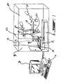
- FIG. 1 illustrates an embodiment of an optical imaging system comprising a system for positioning the mammal 10.
- the system comprises a camera 12, a support 14 for the mammal, and a computer 16 operationally linked to the camera and the optical imaging system.
- the mammal support is preferably a heated tray, and is preferably made of non-reflective substance, that can be moved relative to the optical imaging system. This can be achieved by providing a translation stage 18 on which the tray is mounted. In addition to the motion along the translational stage axis, the tray may also be moved up and down to place the animal in the object plane of the imaging optics.
- the computer may be coupled to the tray in order to provide the user with a means for remotely controlling the position of the tray. Preferably the animal is anesthetized to prevent it from moving during image acquisition.
- the tray may comprise a mask and/or tubes coupled to an anesthetic supply to provide anesthetic to the animal while it is being imaged.
- the tray may also comprise a sensor in order to monitor animal movement during data acquisition.
- the tray may also comprise physiological monitors such as electrocardiograph, temperature sensors, respiration monitors and the like.
- the optical imaging system comprises a combination of mirrors 20 and lens 22 for directing the light source 23 onto the surface of the mammal, and a second set of mirror 24 and lenses 26 is provided for collecting and directing the light re-emitted from the mammal to a detector.
- the detector is in turn linked to the computer, where the acquired optical signals are processed for generating an image.
- a digital image of the surface of the mammal comprising the ROI is acquired by exposing the surface to the field of view of the camera 12.
- the digital image of the ROI permits the user to define the ROI and register the ROI with the optical imaging system as will be described below.
- the digital image is a live image and is continuously updated.
- Software instructions can then be used for proper positioning of the mammal relative to the optical imaging system in order to acquire the optical signals for image reconstruction. Acquisition of the image is preferably performed with the table at a predetermined position relative to the optical imaging system so as to provide an internal reference of coordinates.
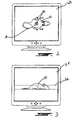
- the ROI may be defined by displaying the image of the surface comprising the ROI on a display screen 28 (FIG. 2).
- the user may then select the ROI 30 using a user interface drawing device, such as a mouse 17, for example.
- the selection of the ROI triggers the computer to digitally record the coordinates of the ROI.
- the coordinates may be stored in a memory for later retrieval.
- the coordinates of the ROI are then used to program the optical imaging system to scan the region defined by the coordinates. This may be accomplished, for example, by programming the position of mirrors to direct the illumination beam and the optical signals re-emitted from the mammal to the appropriate location.
- the user may also define the positions 32 within the ROI where the surface is to be illuminated by the beam of light, and the position where the optical signals re-emitted from the surface of the mammal are to be collected. Selection of illumination and detection points depends on the desired mode of optical imaging (continuous wave, time or frequency domain), the desired resolution, whether the image is topographic or tomographic and the like.
- the system may also comprise a second camera 34 located on a side of the apparatus so as to provide a field of view that is substantially perpendicular to the field of view of the camera used to acquire the digital image of the surface comprising the ROI.
- the second camera allows the acquisition of a digital image that can be used to set the height of the mammal relative to the object plane 36 of the collection optics (FIG. 3).
- the image acquired by the first camera may be stored in the computer and displayed on a screen, overlaid with the live video image, thereby enabling the user to re-align the mammal in a particular plane prior to subsequent scans.
- the plane of imaging may be selected using a user interface device, such as a mouse, for example.
- the system may also comprise means to determine the volumetric profile of the animal.
- the volumetric profile can be determined by scanning the animal with a laser beam directed substantially perpendicularly to the animal. By simultaneously acquiring an image of the laser beam at the surface of the animal with a video camera placed at an angle to the laser path, the volumetric profile may be determined. The animal may be scanned by moving the tray. It will be appreciated that the volumetric profile thus obtained provides spatial information useful for image reconstruction and display.
- the cameras are located in a positioning chamber 38 optically insulated from the chamber 40 comprising the optical components by baffle 42.
- the tray may be moved back and forth between the optical chamber and the positioning chamber by displacement on the translation stage which spans the two compartments. This permits the user to easily manipulate the mammal in the positioning chamber without interfering with or risking disturbing the various optical components.
- fiducial marks may be inscribed on the mammal to provide references that can be used to select the region of interest when a plurality of optical images are acquired over time so that the same region of interest is selected and registered with the optical system.
- the fiducial marks may also be used for registering the optical images with another imaging modality such as computed tomography (CT), magnetic resonance imaging (MRI) and the like.
- CT computed tomography
- MRI magnetic resonance imaging
Landscapes
- Life Sciences & Earth Sciences (AREA)
- Health & Medical Sciences (AREA)
- Surgery (AREA)
- Animal Behavior & Ethology (AREA)
- Pathology (AREA)
- Engineering & Computer Science (AREA)
- Biomedical Technology (AREA)
- Heart & Thoracic Surgery (AREA)
- Medical Informatics (AREA)
- Molecular Biology (AREA)
- Physics & Mathematics (AREA)
- Biophysics (AREA)
- General Health & Medical Sciences (AREA)
- Public Health (AREA)
- Veterinary Medicine (AREA)
- Investigating Or Analysing Materials By Optical Means (AREA)
- Image Processing (AREA)
- Studio Devices (AREA)
- Measuring And Recording Apparatus For Diagnosis (AREA)
- Image Analysis (AREA)
- Apparatus For Radiation Diagnosis (AREA)
- Image Input (AREA)
Abstract
Description
- The invention relates to the field of optical imaging and more specifically to the field of selecting regions of interest in a subject for optical imaging.
- Optical imaging has evolved to become a useful diagnostic tool. Various system designs have been developed to accommodate imaging of various parts of the human body. For example, Hillman et al. (Phys. Med. Biol, 46 (2001)1117-1130) describes an arrangement for acquiring optical signals from a forearm; and Pogue et al. (Opt. Express 1 (1997) 391-403) describes a system for breast imaging. Optical imaging systems have also been developed for small mammals with a view of providing a research tool that can image changes in the physiology of the mammals and that can also provide information on the biodistribution molecules such as chromophores and fluorophores. An example of an optical imaging system for small mammals has been described in patent application WO 0137195.
- Diagnosis as well as physiological and pharmacokinetics studies rely on time course protocols to reveal temporal changes within a subject with respect to predetermined characteristics. Thus, a suitable imaging tool should be able to reliably and reproducibly produce images of the same region of interest in a subject over time. In this respect accurate and reproducible positioning of the subject relative to the imaging optics is very important.
- While the above mentioned optical imaging systems permit the repositioning of a subject in more or less the same position over several imaging sessions, they lack a positioning system that is reliable and precise. Thus there is a need for improved systems and methods for selecting regions of interest in a subject and reproducibly image the selected regions over time.
- The present invention provides a system and method for selecting regions of interest (ROIs) in a subject such as a mammal and for reproducibly positioning the subject to image the same ROIs over time.
- In one aspect of the invention there is provided a method for positioning a small mammal such as a mouse for optical imaging in which a digital image of the mammal is obtained and used to define a ROI by placing the mammal in the field of view of a camera. The ROI is then registered with an optical imaging system and the mammal is positioned relative to the imaging system in accordance with the coordinates of the ROI.
- In an embodiment of the method, the ROI is selected by determining the contour of the ROI on a computer displayed image of a surface comprising the ROI.
- In yet another aspect, a second digital image may be obtained to determine a plane at which the imaging system is focused for acquiring optical data when using an optical system in which light is propagated through air and wherein the optical signal is collected using lenses.
- In yet another embodiment of the method, fiducial marks are inscribed on the subject and can be used as a reference for reproducible positioning of the subject and for selecting the same ROI over time.
- In another aspect of the invention there is also provided a method for positioning a mammal for optical imaging which comprise determining a 3 Dimensional (3 D) contour of at least the part of the animal comprising the ROI and using the 3 D contour information in image reconstruction of the ROI.
- The invention also provides a system for positioning a subject comprising a mammal supporting means, a camera for imaging a surface of the mammal comprising a ROI, storage means for storing the digital image, a display operationally linked to the storage means for displaying the stored digital image, a user interface to define the ROI, and a registering means for registering the defined ROI with an optical imaging system.
- Further features and advantages of the present invention will become apparent from the following detailed description, taken in combination with the appended drawings, in which:
- FIG. 1 is a perspective representation of an embodiment of an optical imaging system comprising a system for positioning a mammal in accordance with the invention;
- FIG. 2 is a computer display illustrating an embodiment of the selection of a region of interest; and
- FIG. 3 is a computer display illustrating the selection of a plane of optical data acquisition according to an embodiment of the invention.
- It will be noted that throughout the appended drawings, like features are identified by like reference numerals.
- The present invention provides a system and method for selecting regions of interest (ROIs) for optical imaging in a subject such as a mammal and for reproducibly positioning the subject to image the same ROIs over time.
- In accordance with one embodiment of the invention, a system for positioning a mammal or part thereof for optical imaging of a ROI of the mammal is provided, which allows the user to select a ROI of the mammal and register the coordinates of the selected region with an optical imaging system. This greatly facilitates manipulation of the mammal with a view of acquiring precise and reproducible optical images. In addition, the system in accordance with the invention permits the programming of the optical imaging system for automatic optical signal acquisition of the desired ROI. Furthermore, the coordinates of the ROI may be stored electronically for future retrieval and advantageously allowing the ROI to be repeatedly imaged over time, with a high degree of reproducibility. This characteristic enables time course experiments to be carried out on mammals by, for example, enabling pharmacokinetic studies, assessment of tumor growth and the like.
- FIG. 1 illustrates an embodiment of an optical imaging system comprising a system for positioning the
mammal 10. In one embodiment, the system comprises acamera 12, asupport 14 for the mammal, and acomputer 16 operationally linked to the camera and the optical imaging system. - The mammal support is preferably a heated tray, and is preferably made of non-reflective substance, that can be moved relative to the optical imaging system. This can be achieved by providing a
translation stage 18 on which the tray is mounted. In addition to the motion along the translational stage axis, the tray may also be moved up and down to place the animal in the object plane of the imaging optics. The computer may be coupled to the tray in order to provide the user with a means for remotely controlling the position of the tray. Preferably the animal is anesthetized to prevent it from moving during image acquisition. In this respect, the tray may comprise a mask and/or tubes coupled to an anesthetic supply to provide anesthetic to the animal while it is being imaged. The tray may also comprise a sensor in order to monitor animal movement during data acquisition. Advantageously the tray may also comprise physiological monitors such as electrocardiograph, temperature sensors, respiration monitors and the like. - The optical imaging system comprises a combination of mirrors 20 and
lens 22 for directing thelight source 23 onto the surface of the mammal, and a second set ofmirror 24 and lenses 26 is provided for collecting and directing the light re-emitted from the mammal to a detector. The detector is in turn linked to the computer, where the acquired optical signals are processed for generating an image. - An embodiment of the method of the present invention is now described. First, a digital image of the surface of the mammal comprising the ROI is acquired by exposing the surface to the field of view of the
camera 12. The digital image of the ROI permits the user to define the ROI and register the ROI with the optical imaging system as will be described below. Preferably the digital image is a live image and is continuously updated. Software instructions can then be used for proper positioning of the mammal relative to the optical imaging system in order to acquire the optical signals for image reconstruction. Acquisition of the image is preferably performed with the table at a predetermined position relative to the optical imaging system so as to provide an internal reference of coordinates. - Once the digital image has been acquired, the ROI may be defined by displaying the image of the surface comprising the ROI on a display screen 28 (FIG. 2). The user may then select the ROI 30 using a user interface drawing device, such as a mouse 17, for example. The selection of the ROI triggers the computer to digitally record the coordinates of the ROI. The coordinates may be stored in a memory for later retrieval.
- The coordinates of the ROI are then used to program the optical imaging system to scan the region defined by the coordinates. This may be accomplished, for example, by programming the position of mirrors to direct the illumination beam and the optical signals re-emitted from the mammal to the appropriate location. In addition to defining the ROI, the user may also define the positions 32 within the ROI where the surface is to be illuminated by the beam of light, and the position where the optical signals re-emitted from the surface of the mammal are to be collected. Selection of illumination and detection points depends on the desired mode of optical imaging (continuous wave, time or frequency domain), the desired resolution, whether the image is topographic or tomographic and the like.
- In a further embodiment, the system may also comprise a second camera 34 located on a side of the apparatus so as to provide a field of view that is substantially perpendicular to the field of view of the camera used to acquire the digital image of the surface comprising the ROI. In optical imaging systems in which the light is propagated through air (i.e. through free space optics) and wherein light re-emitted from the mammal is collected with lenses, the second camera allows the acquisition of a digital image that can be used to set the height of the mammal relative to the
object plane 36 of the collection optics (FIG. 3). Accordingly, the image acquired by the first camera may be stored in the computer and displayed on a screen, overlaid with the live video image, thereby enabling the user to re-align the mammal in a particular plane prior to subsequent scans. As for the selection of the ROI, the plane of imaging may be selected using a user interface device, such as a mouse, for example. - The system may also comprise means to determine the volumetric profile of the animal. In one embodiment, the volumetric profile can be determined by scanning the animal with a laser beam directed substantially perpendicularly to the animal. By simultaneously acquiring an image of the laser beam at the surface of the animal with a video camera placed at an angle to the laser path, the volumetric profile may be determined. The animal may be scanned by moving the tray. It will be appreciated that the volumetric profile thus obtained provides spatial information useful for image reconstruction and display.
- In a preferred embodiment, the cameras are located in a
positioning chamber 38 optically insulated from thechamber 40 comprising the optical components bybaffle 42. In this embodiment, the tray may be moved back and forth between the optical chamber and the positioning chamber by displacement on the translation stage which spans the two compartments. This permits the user to easily manipulate the mammal in the positioning chamber without interfering with or risking disturbing the various optical components. - In another embodiment, fiducial marks may be inscribed on the mammal to provide references that can be used to select the region of interest when a plurality of optical images are acquired over time so that the same region of interest is selected and registered with the optical system. The fiducial marks may also be used for registering the optical images with another imaging modality such as computed tomography (CT), magnetic resonance imaging (MRI) and the like.
- The embodiment(s) of the invention described above is (are) intended to be exemplary only. The scope of the invention is therefore intended to be limited solely by the scope of the appended claims.
Claims (18)
- A method for positioning a mammal or part thereof for optical imaging, the method comprising:i) obtaining a digital image of a surface of the mammal comprising a ROI;ii) defining the ROI;iii) registering coordinates of the ROI with an optical imaging system having collection optics components;iv) positioning the mammal relative to an object plane of the collection optics based on said registered coordinates of said ROI such as to image the ROI.
- The method as claimed in claim 1, wherein the step of obtaining a digital image comprises:i) positioning the mammal on a support so as to expose the surface of the mammal comprising the ROI to a field of view of a camera; andii) acquiring a digital image of the exposed surface.
- The method as claimed in claim 1 or 2, wherein the step of defining the ROI comprises:i) displaying the image of the surface comprising the ROI on a display;ii) selecting the ROI to digitally record coordinates of the ROI; andiii) storing the digitalized coordinates of the ROI in a computer.
- The method as claimed in claim 3, wherein the step of registering the ROI with an optical imaging system comprises programming the optical imaging system to acquire optical data from the ROI defined by the digitalized coordinates.
- The method as claimed in any one of claim 1-4, further comprising the step of selecting a height of the mammal relative to the object plane of the collection optics at which the imaging system is focused for acquiring optical data.
- The method as claimed in claim 5, wherein the step of selecting the height of the mammal comprises:i) obtaining a digital image of a surface of the mammal defined by a plane substantially perpendicular to the plane of the surface of the mammal comprising the ROI;ii) defining a plane corresponding to a desired object plane relative to the mammal at which the imaging system is focused ;iii) digitally recording coordinates of the defined object plane;iv) storing the coordinates of the defined object plane;v) registering the coordinates of the object plane with the imaging system; andvi) positioning the mammal relative to the collecting optics such that the object plane comprises the ROI.
- The method as claimed in any one of claim 1-6 wherein a plurality of images of the ROI are obtained over time and wherein the stored coordinates of the defined plane and of the ROI are used for positioning the mammal at substantially the same position for each image.
- The method as claimed in claim 7 wherein fiducial marks are inscribed on the surface of the mammal in the ROI to provide reference for positioning the mammal at substantially the same position for each image and for selecting substantially the same ROI.
- A method for imaging a mammal or part thereof using an optical imaging system, the method comprising:i) placing said mammal on a supporting means;ii) defining an ROI;iii) obtaining a 3 dimensional (3 D) contour of said animal comprising at least said ROI;iv) registering coordinates of said ROI and 3 D contour with an optical imaging system having collection optics components;v) imaging said ROI of the mammal placed on said supporting means using said optical imaging system wherein said coordinates of said 3 D contour are used in said generation of the image of said ROI.
- The method as claimed in claim 9 wherein said step of obtaining a 3 D contour comprises:i) scanning said ROI with a laser beam directed substantially perpendicularly onto said ROI; andii) simultaneously obtaining an image of said beam at said surface of the mammal.
- A system for positioning a mammal for optical imaging, the system comprising:i) a mammal supporting means;ii) a camera for digitally imaging a surface of the mammal comprising a ROI;iii) storage means for storing the digital image;iv) a display operationally linked to the storage means for displaying the stored digital image;v) a user interface to define the ROI; andvi) a registering means for registering the defined ROI with an optical imaging system.
- The system as claimed in claim 11, wherein the mammal supporting means is a tray.
- The system as claimed in claim 12, wherein the tray is moveable relative to the optical imaging system.
- The system as claimed in claim 12 or 13, wherein the tray is a heated tray.
- The system as claimed in any one of claim 12-14 wherein the tray comprises a motion sensor to detect movement of the mammal during imaging.
- The system as claimed in claim any one of claim 12-15 wherein the tray comprises one or more physiological sensor to monitor desired physiological states in the mammal.
- The system as claimed in any one of claim 11-16, wherein the system further comprises a second camera positioned such as to provide a field of view substantially perpendicular to the field of view of the first camera.
- The system as claimed in claim 17 wherein the first and second camera, the mammal supporting means, the storage means, the display, the user interface and the registering means are operationally linked to a computer.
Applications Claiming Priority (7)
| Application Number | Priority Date | Filing Date | Title |
|---|---|---|---|
| IB0204697 | 2002-11-11 | ||
| WOPCT/IB02/04697 | 2002-11-11 | ||
| US50533902P | 2002-12-12 | 2002-12-12 | |
| US505339P | 2002-12-12 | ||
| US10/624,902 US7366333B2 (en) | 2002-11-11 | 2003-07-23 | Method and apparatus for selecting regions of interest in optical imaging |
| US624902 | 2003-07-23 | ||
| PCT/CA2003/001706 WO2004043246A1 (en) | 2002-11-11 | 2003-11-10 | Method and apparatus for selecting regions of interest in optical imaging |
Publications (2)
| Publication Number | Publication Date |
|---|---|
| EP1565101A1 EP1565101A1 (en) | 2005-08-24 |
| EP1565101B1 true EP1565101B1 (en) | 2006-06-21 |
Family
ID=32314758
Family Applications (1)
| Application Number | Title | Priority Date | Filing Date |
|---|---|---|---|
| EP03773382A Expired - Lifetime EP1565101B1 (en) | 2002-11-11 | 2003-11-10 | Method and apparatus for selecting regions of interest in optical imaging |
Country Status (8)
| Country | Link |
|---|---|
| US (1) | US7366333B2 (en) |
| EP (1) | EP1565101B1 (en) |
| JP (1) | JP2006505376A (en) |
| AT (1) | ATE330537T1 (en) |
| AU (1) | AU2003283107A1 (en) |
| CA (1) | CA2505620A1 (en) |
| DE (1) | DE60306413T2 (en) |
| WO (1) | WO2004043246A1 (en) |
Families Citing this family (18)
| Publication number | Priority date | Publication date | Assignee | Title |
|---|---|---|---|---|
| US8078256B2 (en) | 2002-10-10 | 2011-12-13 | Visualsonics Inc. | Integrated multi-rail imaging system |
| US7190991B2 (en) | 2003-07-01 | 2007-03-13 | Xenogen Corporation | Multi-mode internal imaging |
| US7555334B2 (en) * | 2003-10-20 | 2009-06-30 | Xenogen Corporation | Small animal light intensity monitor |
| US20080039718A1 (en) * | 2006-08-12 | 2008-02-14 | Philometron | Platform for detection of tissue structure change |
| CN102065754A (en) | 2008-04-21 | 2011-05-18 | 善量有限公司 | Metabolic energy monitoring system |
| US9533418B2 (en) * | 2009-05-29 | 2017-01-03 | Cognex Corporation | Methods and apparatus for practical 3D vision system |
| WO2011028926A2 (en) * | 2009-09-02 | 2011-03-10 | Somark Innovations, Inc. | Animal marking devices, transfer assemblies, and useful restraints |
| US8376955B2 (en) * | 2009-09-29 | 2013-02-19 | Covidien Lp | Spectroscopic method and system for assessing tissue temperature |
| EP2684026A4 (en) * | 2011-03-08 | 2014-09-10 | Spectral Instr Imaging Llc | Imaging system having primary and auxiliary camera systems |
| WO2013163339A1 (en) | 2012-04-24 | 2013-10-31 | Somark Innovations, Inc. | Animal marking devices, transfer assemblies, and useful restraints |
| WO2014151852A1 (en) | 2013-03-15 | 2014-09-25 | Somark Innovations, Inc. | Microelectronic animal identification |
| CN103179331B (en) * | 2013-04-18 | 2017-02-08 | 华中科技大学 | Scanning sampling and image processing method of fast imaging |
| KR102395251B1 (en) * | 2015-12-29 | 2022-05-09 | 한국전기연구원 | Method and system for establishing region-of-interest in tomography |
| WO2017136898A1 (en) | 2016-02-11 | 2017-08-17 | Somark Group Limited | A radio device for implantation in an animal, a method for making a radio device for implantation in an animal, a method for providing electrical power to a radio device attached to an animal, a method for implanting a radio device into an animal, an animal having implanted therein a radio device, and a radio device implanted in an animal |
| EP3465539B1 (en) * | 2016-05-27 | 2024-04-17 | Hologic, Inc. | Synchronized surface and internal tumor detection |
| EP3694595B1 (en) | 2017-10-12 | 2025-01-01 | Somark Group Limited | An rfid tag insertion cartridge and an rfid tag insertion tool |
| US11883206B2 (en) | 2019-07-29 | 2024-01-30 | Hologic, Inc. | Personalized breast imaging system |
| US20220164951A1 (en) | 2020-11-20 | 2022-05-26 | Hologic, Inc. | Systems and methods for using ai to identify regions of interest in medical images |
Family Cites Families (15)
| Publication number | Priority date | Publication date | Assignee | Title |
|---|---|---|---|---|
| FR2560037B1 (en) * | 1984-02-28 | 1988-04-08 | Thomson Cgr | METHOD FOR CONTROLLING THE POSITIONING OF A PATIENT IN RELATION TO A RADIOLOGY FACILITY, AND ARRANGEMENT FOR CARRYING OUT SAID METHOD |
| US4896343A (en) * | 1988-05-02 | 1990-01-23 | Saunders Allan M | Radiation apparatus with distance mapper for dose control |
| DE3830183A1 (en) * | 1988-09-06 | 1990-03-15 | Philips Patentverwaltung | METHOD FOR POSITIONING A PATIENT ON A TABLE TOP OF A STORAGE TABLE AND DEVICE FOR CARRYING OUT THE METHOD |
| US6405072B1 (en) * | 1991-01-28 | 2002-06-11 | Sherwood Services Ag | Apparatus and method for determining a location of an anatomical target with reference to a medical apparatus |
| DE4207632C2 (en) * | 1992-03-11 | 1995-07-20 | Bodenseewerk Geraetetech | Device and method for positioning a body part for treatment purposes |
| US5531520A (en) * | 1994-09-01 | 1996-07-02 | Massachusetts Institute Of Technology | System and method of registration of three-dimensional data sets including anatomical body data |
| US5894615A (en) * | 1995-10-25 | 1999-04-20 | Alexander; Marvin J. | Temperature selectively controllable body supporting pad |
| US5823192A (en) * | 1996-07-31 | 1998-10-20 | University Of Pittsburgh Of The Commonwealth System Of Higher Education | Apparatus for automatically positioning a patient for treatment/diagnoses |
| US5727554A (en) * | 1996-09-19 | 1998-03-17 | University Of Pittsburgh Of The Commonwealth System Of Higher Education | Apparatus responsive to movement of a patient during treatment/diagnosis |
| US6396940B1 (en) * | 1999-05-27 | 2002-05-28 | Litton Systems, Inc. | Optical correlator based automated pathologic region of interest selector for integrated 3D ultrasound and digital mammography |
| US6614452B1 (en) * | 1999-11-15 | 2003-09-02 | Xenogen Corporation | Graphical user interface for in-vivo imaging |
| WO2001082786A2 (en) | 2000-05-03 | 2001-11-08 | Flock Stephen T | Optical imaging of subsurface anatomical structures and biomolecules |
| DE10109219B4 (en) * | 2001-02-26 | 2005-07-07 | Siemens Ag | Positioning device for diagnostic imaging systems |
| DE10132808B4 (en) * | 2001-07-06 | 2005-07-28 | Siemens Ag | Optical diagnostic system for small animal imaging |
| US6992762B2 (en) * | 2002-11-11 | 2006-01-31 | Art Advanced Research Technologies Inc. | Method and apparatus for time resolved optical imaging of biological tissues as part of animals |
-
2003
- 2003-07-23 US US10/624,902 patent/US7366333B2/en not_active Expired - Fee Related
- 2003-11-10 CA CA002505620A patent/CA2505620A1/en not_active Abandoned
- 2003-11-10 JP JP2005506632A patent/JP2006505376A/en not_active Withdrawn
- 2003-11-10 AU AU2003283107A patent/AU2003283107A1/en not_active Abandoned
- 2003-11-10 EP EP03773382A patent/EP1565101B1/en not_active Expired - Lifetime
- 2003-11-10 WO PCT/CA2003/001706 patent/WO2004043246A1/en not_active Ceased
- 2003-11-10 DE DE60306413T patent/DE60306413T2/en not_active Expired - Lifetime
- 2003-11-10 AT AT03773382T patent/ATE330537T1/en not_active IP Right Cessation
Also Published As
| Publication number | Publication date |
|---|---|
| EP1565101A1 (en) | 2005-08-24 |
| AU2003283107A1 (en) | 2004-06-03 |
| JP2006505376A (en) | 2006-02-16 |
| US20040131234A1 (en) | 2004-07-08 |
| CA2505620A1 (en) | 2004-05-27 |
| DE60306413T2 (en) | 2007-06-14 |
| DE60306413D1 (en) | 2006-08-03 |
| US7366333B2 (en) | 2008-04-29 |
| WO2004043246A1 (en) | 2004-05-27 |
| ATE330537T1 (en) | 2006-07-15 |
Similar Documents
| Publication | Publication Date | Title |
|---|---|---|
| EP1565101B1 (en) | Method and apparatus for selecting regions of interest in optical imaging | |
| US8388539B2 (en) | Operation supporting device, method, and program | |
| US5920395A (en) | System for locating relative positions of objects in three dimensional space | |
| US4722056A (en) | Reference display systems for superimposing a tomagraphic image onto the focal plane of an operating microscope | |
| US6259942B1 (en) | Method and apparatus for recording a three-dimensional image of a body part | |
| US5704897A (en) | Apparatus and method for registration of points of a data field with respective points of an optical image | |
| JP3565851B2 (en) | Infrared angiography system | |
| US6427022B1 (en) | Image comparator system and method for detecting changes in skin lesions | |
| JP3454235B2 (en) | Biomagnetic field measurement device | |
| JP2001500772A (en) | Image guided surgery system | |
| JPH11510423A (en) | Image guided surgery system | |
| JP2006122086A (en) | Biological light measurement device | |
| CN101568293A (en) | Method and apparatus for retinal diagnosis | |
| JP2004049911A (en) | Method and apparatus for positioning a patient in a medical diagnostic or therapeutic device | |
| JPH10211196A (en) | X-ray ct scanner | |
| US20120197112A1 (en) | Spatially-localized optical coherence tomography imaging | |
| JP4330181B2 (en) | Imaging modality for image guided surgery | |
| CN112102469B (en) | Three-dimensional modeling system, scanning system and control method thereof | |
| CN1735372A (en) | Method and apparatus for selecting region of interest in optics imaging | |
| CN116839500A (en) | Imaging system for simultaneously extracting internal fluorescent molecular distribution and surface three-dimensional structure |
Legal Events
| Date | Code | Title | Description |
|---|---|---|---|
| PUAI | Public reference made under article 153(3) epc to a published international application that has entered the european phase |
Free format text: ORIGINAL CODE: 0009012 |
|
| 17P | Request for examination filed |
Effective date: 20050610 |
|
| AK | Designated contracting states |
Kind code of ref document: A1 Designated state(s): AT BE BG CH CY CZ DE DK EE ES FI FR GB GR HU IE IT LI LU MC NL PT RO SE SI SK TR |
|
| AX | Request for extension of the european patent |
Extension state: AL LT LV MK |
|
| GRAP | Despatch of communication of intention to grant a patent |
Free format text: ORIGINAL CODE: EPIDOSNIGR1 |
|
| DAX | Request for extension of the european patent (deleted) | ||
| GRAS | Grant fee paid |
Free format text: ORIGINAL CODE: EPIDOSNIGR3 |
|
| GRAA | (expected) grant |
Free format text: ORIGINAL CODE: 0009210 |
|
| REG | Reference to a national code |
Ref country code: HK Ref legal event code: DE Ref document number: 1081827 Country of ref document: HK |
|
| RAP1 | Party data changed (applicant data changed or rights of an application transferred) |
Owner name: ART ADVANCED RESEARCH TECHNOLOGIES INC. |
|
| AK | Designated contracting states |
Kind code of ref document: B1 Designated state(s): AT BE BG CH CY CZ DE DK EE ES FI FR GB GR HU IE IT LI LU MC NL PT RO SE SI SK TR |
|
| PG25 | Lapsed in a contracting state [announced via postgrant information from national office to epo] |
Ref country code: IT Free format text: LAPSE BECAUSE OF FAILURE TO SUBMIT A TRANSLATION OF THE DESCRIPTION OR TO PAY THE FEE WITHIN THE PRESCRIBED TIME-LIMIT;WARNING: LAPSES OF ITALIAN PATENTS WITH EFFECTIVE DATE BEFORE 2007 MAY HAVE OCCURRED AT ANY TIME BEFORE 2007. THE CORRECT EFFECTIVE DATE MAY BE DIFFERENT FROM THE ONE RECORDED. Effective date: 20060621 Ref country code: BE Free format text: LAPSE BECAUSE OF FAILURE TO SUBMIT A TRANSLATION OF THE DESCRIPTION OR TO PAY THE FEE WITHIN THE PRESCRIBED TIME-LIMIT Effective date: 20060621 Ref country code: AT Free format text: LAPSE BECAUSE OF FAILURE TO SUBMIT A TRANSLATION OF THE DESCRIPTION OR TO PAY THE FEE WITHIN THE PRESCRIBED TIME-LIMIT Effective date: 20060621 Ref country code: CH Free format text: LAPSE BECAUSE OF FAILURE TO SUBMIT A TRANSLATION OF THE DESCRIPTION OR TO PAY THE FEE WITHIN THE PRESCRIBED TIME-LIMIT Effective date: 20060621 Ref country code: RO Free format text: LAPSE BECAUSE OF FAILURE TO SUBMIT A TRANSLATION OF THE DESCRIPTION OR TO PAY THE FEE WITHIN THE PRESCRIBED TIME-LIMIT Effective date: 20060621 Ref country code: SI Free format text: LAPSE BECAUSE OF FAILURE TO SUBMIT A TRANSLATION OF THE DESCRIPTION OR TO PAY THE FEE WITHIN THE PRESCRIBED TIME-LIMIT Effective date: 20060621 Ref country code: LI Free format text: LAPSE BECAUSE OF FAILURE TO SUBMIT A TRANSLATION OF THE DESCRIPTION OR TO PAY THE FEE WITHIN THE PRESCRIBED TIME-LIMIT Effective date: 20060621 Ref country code: FI Free format text: LAPSE BECAUSE OF FAILURE TO SUBMIT A TRANSLATION OF THE DESCRIPTION OR TO PAY THE FEE WITHIN THE PRESCRIBED TIME-LIMIT Effective date: 20060621 Ref country code: CZ Free format text: LAPSE BECAUSE OF FAILURE TO SUBMIT A TRANSLATION OF THE DESCRIPTION OR TO PAY THE FEE WITHIN THE PRESCRIBED TIME-LIMIT Effective date: 20060621 Ref country code: NL Free format text: LAPSE BECAUSE OF FAILURE TO SUBMIT A TRANSLATION OF THE DESCRIPTION OR TO PAY THE FEE WITHIN THE PRESCRIBED TIME-LIMIT Effective date: 20060621 Ref country code: SK Free format text: LAPSE BECAUSE OF FAILURE TO SUBMIT A TRANSLATION OF THE DESCRIPTION OR TO PAY THE FEE WITHIN THE PRESCRIBED TIME-LIMIT Effective date: 20060621 |
|
| REG | Reference to a national code |
Ref country code: GB Ref legal event code: FG4D |
|
| REG | Reference to a national code |
Ref country code: CH Ref legal event code: EP |
|
| REG | Reference to a national code |
Ref country code: IE Ref legal event code: FG4D |
|
| REF | Corresponds to: |
Ref document number: 60306413 Country of ref document: DE Date of ref document: 20060803 Kind code of ref document: P |
|
| PG25 | Lapsed in a contracting state [announced via postgrant information from national office to epo] |
Ref country code: SE Free format text: LAPSE BECAUSE OF FAILURE TO SUBMIT A TRANSLATION OF THE DESCRIPTION OR TO PAY THE FEE WITHIN THE PRESCRIBED TIME-LIMIT Effective date: 20060921 Ref country code: DK Free format text: LAPSE BECAUSE OF FAILURE TO SUBMIT A TRANSLATION OF THE DESCRIPTION OR TO PAY THE FEE WITHIN THE PRESCRIBED TIME-LIMIT Effective date: 20060921 |
|
| PG25 | Lapsed in a contracting state [announced via postgrant information from national office to epo] |
Ref country code: ES Free format text: LAPSE BECAUSE OF FAILURE TO SUBMIT A TRANSLATION OF THE DESCRIPTION OR TO PAY THE FEE WITHIN THE PRESCRIBED TIME-LIMIT Effective date: 20061002 |
|
| PG25 | Lapsed in a contracting state [announced via postgrant information from national office to epo] |
Ref country code: IE Free format text: LAPSE BECAUSE OF NON-PAYMENT OF DUE FEES Effective date: 20061110 |
|
| PG25 | Lapsed in a contracting state [announced via postgrant information from national office to epo] |
Ref country code: PT Free format text: LAPSE BECAUSE OF FAILURE TO SUBMIT A TRANSLATION OF THE DESCRIPTION OR TO PAY THE FEE WITHIN THE PRESCRIBED TIME-LIMIT Effective date: 20061121 |
|
| PG25 | Lapsed in a contracting state [announced via postgrant information from national office to epo] |
Ref country code: MC Free format text: LAPSE BECAUSE OF NON-PAYMENT OF DUE FEES Effective date: 20061130 |
|
| NLV1 | Nl: lapsed or annulled due to failure to fulfill the requirements of art. 29p and 29m of the patents act | ||
| REG | Reference to a national code |
Ref country code: CH Ref legal event code: PL |
|
| ET | Fr: translation filed | ||
| PLBE | No opposition filed within time limit |
Free format text: ORIGINAL CODE: 0009261 |
|
| STAA | Information on the status of an ep patent application or granted ep patent |
Free format text: STATUS: NO OPPOSITION FILED WITHIN TIME LIMIT |
|
| 26N | No opposition filed |
Effective date: 20070322 |
|
| REG | Reference to a national code |
Ref country code: GB Ref legal event code: 732E |
|
| REG | Reference to a national code |
Ref country code: FR Ref legal event code: TP Ref country code: FR Ref legal event code: CD |
|
| PG25 | Lapsed in a contracting state [announced via postgrant information from national office to epo] |
Ref country code: GR Free format text: LAPSE BECAUSE OF FAILURE TO SUBMIT A TRANSLATION OF THE DESCRIPTION OR TO PAY THE FEE WITHIN THE PRESCRIBED TIME-LIMIT Effective date: 20060922 |
|
| PG25 | Lapsed in a contracting state [announced via postgrant information from national office to epo] |
Ref country code: BG Free format text: LAPSE BECAUSE OF FAILURE TO SUBMIT A TRANSLATION OF THE DESCRIPTION OR TO PAY THE FEE WITHIN THE PRESCRIBED TIME-LIMIT Effective date: 20060921 Ref country code: EE Free format text: LAPSE BECAUSE OF FAILURE TO SUBMIT A TRANSLATION OF THE DESCRIPTION OR TO PAY THE FEE WITHIN THE PRESCRIBED TIME-LIMIT Effective date: 20060621 |
|
| PG25 | Lapsed in a contracting state [announced via postgrant information from national office to epo] |
Ref country code: LU Free format text: LAPSE BECAUSE OF NON-PAYMENT OF DUE FEES Effective date: 20061110 Ref country code: HU Free format text: LAPSE BECAUSE OF FAILURE TO SUBMIT A TRANSLATION OF THE DESCRIPTION OR TO PAY THE FEE WITHIN THE PRESCRIBED TIME-LIMIT Effective date: 20061222 Ref country code: TR Free format text: LAPSE BECAUSE OF FAILURE TO SUBMIT A TRANSLATION OF THE DESCRIPTION OR TO PAY THE FEE WITHIN THE PRESCRIBED TIME-LIMIT Effective date: 20060621 |
|
| PG25 | Lapsed in a contracting state [announced via postgrant information from national office to epo] |
Ref country code: CY Free format text: LAPSE BECAUSE OF FAILURE TO SUBMIT A TRANSLATION OF THE DESCRIPTION OR TO PAY THE FEE WITHIN THE PRESCRIBED TIME-LIMIT Effective date: 20060621 |
|
| REG | Reference to a national code |
Ref country code: FR Ref legal event code: TP Ref country code: FR Ref legal event code: CD |
|
| REG | Reference to a national code |
Ref country code: GB Ref legal event code: 732E Free format text: REGISTERED BETWEEN 20110728 AND 20110803 |
|
| REG | Reference to a national code |
Ref country code: DE Ref legal event code: R082 Ref document number: 60306413 Country of ref document: DE Representative=s name: WEICKMANN & WEICKMANN, DE |
|
| REG | Reference to a national code |
Ref country code: DE Ref legal event code: R082 Ref document number: 60306413 Country of ref document: DE Representative=s name: PATENTANWAELTE WEICKMANN & WEICKMANN, DE Effective date: 20111017 Ref country code: DE Ref legal event code: R081 Ref document number: 60306413 Country of ref document: DE Owner name: SOFTSCAN HEALTHCARE GROUP LTD., ROAD TOWN, VG Free format text: FORMER OWNER: ART ADVANCED RESEARCH TECHNOLOGIES INC., ST.LAURENT, QUEBEC, CA Effective date: 20111017 |
|
| REG | Reference to a national code |
Ref country code: HK Ref legal event code: WD Ref document number: 1081827 Country of ref document: HK |
|
| PGFP | Annual fee paid to national office [announced via postgrant information from national office to epo] |
Ref country code: DE Payment date: 20121031 Year of fee payment: 10 Ref country code: FR Payment date: 20121130 Year of fee payment: 10 |
|
| PGFP | Annual fee paid to national office [announced via postgrant information from national office to epo] |
Ref country code: GB Payment date: 20121120 Year of fee payment: 10 Ref country code: IT Payment date: 20121127 Year of fee payment: 10 |
|
| GBPC | Gb: european patent ceased through non-payment of renewal fee |
Effective date: 20131110 |
|
| REG | Reference to a national code |
Ref country code: FR Ref legal event code: ST Effective date: 20140731 |
|
| REG | Reference to a national code |
Ref country code: DE Ref legal event code: R119 Ref document number: 60306413 Country of ref document: DE Effective date: 20140603 |
|
| PG25 | Lapsed in a contracting state [announced via postgrant information from national office to epo] |
Ref country code: IT Free format text: LAPSE BECAUSE OF NON-PAYMENT OF DUE FEES Effective date: 20131110 Ref country code: DE Free format text: LAPSE BECAUSE OF NON-PAYMENT OF DUE FEES Effective date: 20140603 |
|
| PG25 | Lapsed in a contracting state [announced via postgrant information from national office to epo] |
Ref country code: FR Free format text: LAPSE BECAUSE OF NON-PAYMENT OF DUE FEES Effective date: 20131202 Ref country code: GB Free format text: LAPSE BECAUSE OF NON-PAYMENT OF DUE FEES Effective date: 20131110 |