EP1564865A1 - Machine having salient poles with at least one winding on the pole - Google Patents
Machine having salient poles with at least one winding on the pole Download PDFInfo
- Publication number
- EP1564865A1 EP1564865A1 EP04003171A EP04003171A EP1564865A1 EP 1564865 A1 EP1564865 A1 EP 1564865A1 EP 04003171 A EP04003171 A EP 04003171A EP 04003171 A EP04003171 A EP 04003171A EP 1564865 A1 EP1564865 A1 EP 1564865A1
- Authority
- EP
- European Patent Office
- Prior art keywords
- pole
- spring
- coil
- salient
- machine according
- Prior art date
- Legal status (The legal status is an assumption and is not a legal conclusion. Google has not performed a legal analysis and makes no representation as to the accuracy of the status listed.)
- Withdrawn
Links
Images
Classifications
-
- H—ELECTRICITY
- H02—GENERATION; CONVERSION OR DISTRIBUTION OF ELECTRIC POWER
- H02K—DYNAMO-ELECTRIC MACHINES
- H02K3/00—Details of windings
- H02K3/46—Fastening of windings on the stator or rotor structure
- H02K3/52—Fastening salient pole windings or connections thereto
- H02K3/527—Fastening salient pole windings or connections thereto applicable to rotors only
Definitions
- the invention relates to a salient pole with at least one in an axial direction of the Pole spool extending pole coil under a Pole shoe is arranged on a running body.
- EP 0 415 057 B1 an arrangement for the forced supply of a cooling medium in a gap between a pole core of the rotor body and the Pole coil known in the gap between pole core and Pole coil is provided a guide, which the Split divided into two spaces, which is essentially only on pole cap end of the gap in free connection and otherwise flows through one after the other.
- a guide which the Split divided into two spaces, which is essentially only on pole cap end of the gap in free connection and otherwise flows through one after the other.
- Such Guide device is relatively expensive produce and needs a suitably adapted, special assembly.
- the invention is based on the object Schenkelpolmaschine of the type mentioned in addition to improve that arranged on the rotor body pole coils be cooled better in a relatively inexpensive way.
- the object is according to the invention with a generic Schenkelpolmaschine solved in which the pole coil means at least one between the pole coil and the rotor body arranged spring urged against the pole piece and by that of the spring between the pole coil and the rotor body produced distance an axial cooling channel is created.
- the object is further achieved with a salient pole machine, in which the pole coil by means of at least one between the Pole coil and the rotor body arranged spring against the Polschuh is pushed, which is designed as a leaf spring.
- Schenkelpolmaschine is that between the pole coil and the Rotor body provided spring with at least one in Essentially formed U-shaped section and with a the two legs of this substantially U-shaped Section is the pole coil against the associated pole piece crowded.
- the space inside the U-shaped section serves then as a passage for forming the axial according to the invention Cooling channel.
- a spring with two is advantageous Essentially U-shaped, partially overlapping one another Provided sections that share essentially an O-shape form, which is open in one place.
- Such "annular" spring can with appropriate design in radial direction apply a high spring force and provides nevertheless in their interior a comparatively large one Through opening as a cooling channel available.
- the O-shaped spring should be at least a fastener at the opening of the O-shape attached to the runner body opposite side of the O-shape be. The spring is then securely held on the runner body, while their two are essentially semi-cylindrical Spring arms each one of two pole coils against the push the corresponding pole piece.
- the spring stiffness of the invention provided spring should be advantageously between about 1 and 4 N / mm, in particular between about 2 and 3 N / mm.
- Winding height tolerance of +/- 2mm can be compensated.
- two leaf springs can be inserted into each other or side by side.
- the area load between the spring and the pole coil or an insulation element arranged there should be within the limits of about 20 to 30 N / mm 2 .
- the spring is so is shaped that in the tensioned state of their investment point or Area at the associated pole coil or at one there arranged isolation element of the gravity axis of the Pole coil is slightly removed.
- the distance between Focus axis and investment point should especially between 2 and 5 mm, most preferably 3.5 mm.
- the spring is advantageous in particular a greater travel and a flatter course of Spring force.
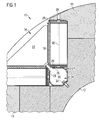
- a substantially cylindrical one Femoral pole rotor 10 of a salient pole generator shown a runner body 12 and on the outside thereof arranged elongated pole pieces 14 has. Between each two elongated pole pieces 14 is a substantially in Cross-section triangular recess 16 formed in Shape of a groove also over the entire length of Runner body 12 extends.
- Pole coil 18 In a single recess 16 are each two in the axial direction of the salient pole runner 10 extending Pole coil 18 is arranged, each in an insulating frame 20th are embedded.
- the pole coils 18 are each at the Leg sides of the cross-sectionally triangular recess 16 on the rotor body 12 and are at their radially outer Enveloped end areas of each pole piece 14. Between the two pole coils 18 is also in the Cross section substantially triangular coil support 22 arranged by means of the pole coils in the recess 16th are restrained.
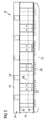
- Cooling medium particularly effective on the pole coils 18th can absorb the resulting heat energy, are the pole coils 18 each of a plurality of radial cooling channels 36th interspersed, in the axial direction in particular between two leaf springs 24 are formed in the pole coils 18 are.
- the radial cooling channels 36 extend starting from the axial cooling passage 34 through the insulating frame 20 and the associated pole coil 18. They lead to associated Air outlet openings 38, the coordinated pole pieces 14th pass through and to the outside of the femoral pole runner 10 to lead. Through the radial cooling channels can in this way the cooling medium supplied through the axial cooling channels 34 be discharged through the pole coils 18 therethrough.
Landscapes
- Engineering & Computer Science (AREA)
- Power Engineering (AREA)
- Motor Or Generator Cooling System (AREA)
- Iron Core Of Rotating Electric Machines (AREA)
- Windings For Motors And Generators (AREA)
- Synchronous Machinery (AREA)
- Insulation, Fastening Of Motor, Generator Windings (AREA)
Abstract
Description
Die Erfindung betrifft eine Schenkelpolmaschine mit mindestens einer sich in einer axialen Richtung der Schenkelpolmaschine erstreckenden Polspule, die unter einem Polschuh an einem Laufkörper angeordnet ist.The invention relates to a salient pole with at least one in an axial direction of the Pole spool extending pole coil under a Pole shoe is arranged on a running body.
Bei Schenkelpolmaschinen, wie z.B. Schenkelpolgeneratoren,
bereitet die Kühlung der Pol- bzw. Erregerwicklung eines
zugehörigen Schenkelpolläufers oft erhebliche technische
Schwierigkeiten. Während es für die Kühlluftführung in
Pollücken des Schenkelpolläufers bereits eine Reihe von
technisch einwandfreien und funktionsfähigen Vorschlägen
gibt, sind die bisher bekannten Maßnahmen zur
Polspulenkühlung, also der Abfuhr der Wärme zur Begrenzung
der Temperatur der Polspulen von Schenkelpolmaschinen, bisher
wenig befriedigend. So ist beispielsweise aus EP 0 415 057 B1
eine Anordnung zur forcierten Zufuhr eines Kühlmediums in
einen Spalt zwischen einem Polkern des Läuferkörpers und der
Polspule bekannt, bei der im Spalt zwischen Polkern und
Polspule eine Leiteinrichtung vorgesehen ist, welche den
Spalt in zwei Räume unterteilt, die im Wesentlichen nur am
polkappenseitigen Ende des Spalts in freier Verbindung stehen
und ansonsten nacheinander durchströmt werden. Eine solche
Leiteinrichtung ist jedoch vergleichsweise aufwendig
herzustellen und bedarf einer entsprechend angepassten,
besonderen Montage.In salient pole machines, such as e.g. salient pole,
Prepares the cooling of the pole or excitation winding of a
associated Schellenpolläufers often considerable technical
Difficulties. While it is for the cooling air flow in
Pole - blcks of the femur polling already a series of
technically sound and functioning proposals
There are the previously known measures for
Pole coil cooling, ie the dissipation of heat to limit
the temperature of the pole coils of salient pole machines, so far
not very satisfactory. For example,
Aus DE 198 10 628 A1 ist ein Belüftungssystem für die Erregerwicklung bzw. Polspule großer Schenkelpolmaschinen bekannt, bei dem parallel zu dem Strömungsweg in der Pollücke zusätzlich Strömungswege im Kopf von Flachkupferleitern der Polspule ausgebildet sind. Die damit ausgebildeten parallelen Strömungswege durchlaufen alle Flachkupferleiter und die zugehörigen Isolierschichten. Die Strömungswege schwächen jedoch die Polspulen und führen unter bestimmten Umständen nicht zu der erwarteten Kühlleistung.From DE 198 10 628 A1 is a ventilation system for the Exciter winding or pole coil of large salient pole machines known, in parallel to the flow path in the pole gap additionally flow paths in the head of flat copper ladders Pole coil are formed. The trained parallel Flow paths go through all the flat copper conductors and the associated insulating layers. Weaken the flow paths however, the pole coils and lead in certain circumstances not to the expected cooling capacity.
Der Erfindung liegt die Aufgabe zugrunde, eine Schenkelpolmaschine der eingangs genannten Art dahingehend zu verbessern, dass die am Läuferkörper angeordneten Polspulen auf vergleichsweise kostengünstige Art besser gekühlt werden.The invention is based on the object Schenkelpolmaschine of the type mentioned in addition to improve that arranged on the rotor body pole coils be cooled better in a relatively inexpensive way.
Die Aufgabe ist erfindungsgemäß mit einer gattungsgemäßen Schenkelpolmaschine gelöst, bei der die Polspule mittels mindestens einer zwischen der Polspule und dem Läuferkörper angeordneten Feder gegen den Polschuh gedrängt sowie durch den von der Feder zwischen der Polspule und dem Läuferkörper hergestellten Abstand ein axialer Kühlkanal geschaffen ist. Die Aufgabe ist ferner mit einer Schenkelpolmaschine gelöst, bei der die Polspule mittels mindestens einer zwischen der Polspule und dem Läuferkörper angeordneten Feder gegen den Polschuh gedrängt ist, die als Blattfeder gestaltet ist.The object is according to the invention with a generic Schenkelpolmaschine solved in which the pole coil means at least one between the pole coil and the rotor body arranged spring urged against the pole piece and by that of the spring between the pole coil and the rotor body produced distance an axial cooling channel is created. The object is further achieved with a salient pole machine, in which the pole coil by means of at least one between the Pole coil and the rotor body arranged spring against the Polschuh is pushed, which is designed as a leaf spring.
Durch die erfindungsgemäße Abstützung der Polspule durch eine oder mehrere unter der Polspule angeordnete Federn und wird gemäß der Erfindung zugleich ein axialer Kühlkanal geschaffen, durch den Kühlmedium zu den Polspulen zugeführt werden kann. Diese erfindungsgemäße Art der Kühlung von Polspulen erfordert keine zusätzliche Leiteinrichtung und ist daher vergleichsweise kostengünstig herzustellen und zu montieren. Durch die erfindungsgemäße Abstützung der Polspule durch eine oder mehrere unter der Polspule angeordnete Blattfedern, können Querschnitte geschaffen werden, die einen vergleichsweise geringen Strömungswiderstand aufweisen. Die erfindungsgemäß geschaffenen Räume können daher besonders gut für eine axiale Kühlmediumsführung unterhalb der Polspule genutzt werden.By the inventive support of the pole coil by a or more below the pole coil arranged springs and is according to the invention at the same time an axial cooling channel created supplied by the cooling medium to the pole coils can be. This inventive type of cooling of Pole coils requires no additional guide and is therefore comparatively inexpensive to manufacture and assemble. By the inventive support of the pole coil by one or more arranged below the pole coil Leaf springs, cross sections can be created, the one have comparatively low flow resistance. The According to the invention created spaces can therefore be particularly good for an axial cooling medium guide below the pole coil be used.
Bei einer vorteilhaften Weiterbildung der erfindungsgemäßen Schenkelpolmaschine ist die zwischen der Polspule und dem Läuferkörper vorgesehene Feder mit mindestens einem im Wesentlichen U-förmigen Abschnitt ausgebildet und mit einem der beiden Schenkel dieses im Wesentlichen U-förmigen Abschnitts ist die Polspule gegen den zugehörigen Polschuh gedrängt. Der Raum im Inneren des U-förmigen Abschnitts dient dann als Durchlass zum Bilden des erfindungsgemäßen axialen Kühlkanals.In an advantageous embodiment of the invention Schenkelpolmaschine is that between the pole coil and the Rotor body provided spring with at least one in Essentially formed U-shaped section and with a the two legs of this substantially U-shaped Section is the pole coil against the associated pole piece crowded. The space inside the U-shaped section serves then as a passage for forming the axial according to the invention Cooling channel.
Darüber hinaus ist vorteilhaft eine Feder mit zwei im Wesentlichen U-förmigen, einander teilweise überdeckenden Abschnitten vorgesehen, die gemeinsam im Wesentlichen eine O-Form bilden, welche an einer Stelle geöffnet ist. Eine solche "ringförmige" Feder kann bei entsprechender Gestaltung in radialer Richtung eine hohe Federkraft aufbringen und stellt dennoch in ihrem Inneren eine vergleichsweise große Durchgangsöffnung als Kühlkanal zur Verfügung.In addition, a spring with two is advantageous Essentially U-shaped, partially overlapping one another Provided sections that share essentially an O-shape form, which is open in one place. Such "annular" spring can with appropriate design in radial direction apply a high spring force and provides nevertheless in their interior a comparatively large one Through opening as a cooling channel available.
Ferner können mit einer solchen O-förmigen Feder zwei Polspulen gegen jeweils einen zugehörigen Polschuh gedrängt werden, so dass insgesamt nur vergleichsweise wenige Federn an einer solchen erfindungsgemäßen Schenkelpolmaschine einzusetzen sind. Die eingesetzten O-förmigen Federn sollten mit ihrer Öffnung dabei so angeordnet sein, dass diese zu einer zwischen den beiden Polspulen angeordneten Spulenstütze gerichtet sind.Furthermore, with such an O-shaped spring two Poles pushed against each associated pole piece so that in total only comparatively few springs on such a Schenkelpolmaschine invention are to be used. The inserted O-shaped springs should with its opening thereby arranged so that these too a coil support arranged between the two pole coils are directed.
Darüber hinaus sollte die O-förmige Feder mit mindestens einem Befestigungsmittel an der der Öffnung der O-Form gegenüberliegenden Seite der O-Form am Läuferkörper befestigt sein. Die Feder ist dann am Läuferkörper sicher gehaltert, während ihre beiden im Wesentlichen halbzylinderischen Federarme jeweils eine von zwei Polspulen gegen den zugehörigen Polschuh drängen.In addition, the O-shaped spring should be at least a fastener at the opening of the O-shape attached to the runner body opposite side of the O-shape be. The spring is then securely held on the runner body, while their two are essentially semi-cylindrical Spring arms each one of two pole coils against the push the corresponding pole piece.
Die Federsteifigkeit der erfindungsgemäß vorgesehenen Feder sollte vorteilhaft zwischen ca. 1 und 4 N/mm, insbesondere zwischen ca. 2 und 3 N/mm liegen. Mit einer solchen Feder kann beispielsweise eine geforderte Polspulen- bzw. The spring stiffness of the invention provided spring should be advantageously between about 1 and 4 N / mm, in particular between about 2 and 3 N / mm. With such a spring For example, a required Polspulen- or
Wicklungshöhentoleranz von +/- 2mm ausgeglichen werden. Um die geforderte Federsteifigkeit zu erreichen, können auch zwei Blattfedern ineinander oder nebeneinander eingesetzt werden. Die Flächenlast zwischen der Feder und der Polspule bzw. einem dort angeordneten Isolationselement (beispielsweise einem GFK-Teil, d.h. einem glasfaserverstärkten Kunststoff) sollte in den Grenzen von ca. 20 - 30 N/mm2 liegen.Winding height tolerance of +/- 2mm can be compensated. To achieve the required spring stiffness, two leaf springs can be inserted into each other or side by side. The area load between the spring and the pole coil or an insulation element arranged there (for example a GFRP part, ie a glass fiber reinforced plastic) should be within the limits of about 20 to 30 N / mm 2 .
Hinsichtlich der Gestaltung der erfindungsgemäßen Feder ist es schließlich auch vorteilhaft, wenn die Feder derart geformt ist, dass im gespannten Zustand ihr Anlagepunkt bzw. Bereich an der zugehörigen Polspule oder an einem dort angeordneten Isolationselement von der Schwerpunktachse der Polspule geringfügig entfernt ist. Der Abstand zwischen Schwerpunktachse und Anlagepunkt sollte insbesondere zwischen 2 und 5 mm, am Bevorzugtesten 3,5 mm betragen. Eine solche geringfügige Verschiebung des Anlagepunkts der erfindungsgemäßen Feder führt vorteilhaft insbesondere zu einem größeren Federweg und einem flacheren Verlauf der Federkraft.With regard to the design of the spring according to the invention Finally, it also benefits when the spring is so is shaped that in the tensioned state of their investment point or Area at the associated pole coil or at one there arranged isolation element of the gravity axis of the Pole coil is slightly removed. The distance between Focus axis and investment point should especially between 2 and 5 mm, most preferably 3.5 mm. Such slight shift of the investment point of the According to the invention, the spring is advantageous in particular a greater travel and a flatter course of Spring force.
Um die erfindungsgemäß verbesserte Kühlung der Polspulen
einer Schenkelpolmaschine weiter zu optimieren, sollte in der
mindestens einen Polspule mindestens ein im Wesentlichen
radial gerichteter Kühlkanal ausgebildet sein, mittels dem
eine fluidleitende Verbindung zwischen dem genannten axialen
Kühlkanal und der Außenseite des Polschuhs hergestellt ist.
Nachfolgend wird ein Ausführungsbeispiel einer
erfindungsgemäßen Schenkelpolmaschine anhand der beigefügten
schematischen Zeichnungen näher erläutert. Es zeigt:
In Fig.1 ist ein im Wesentlichen zylindrischer
Schenkelpolläufer 10 eines Schenkelpolgenerators dargestellt,
der einen Läuferkörper 12 und an dessen Außenseite
angeordnete längliche Polschuhe 14 aufweist. Zwischen jeweils
zwei länglichen Polschuhen 14 ist eine im Wesentlichen im
Querschnitt dreieckige Aussparung 16 ausgebildet, die sich in
Gestalt einer Nut ebenfalls über die gesamte Länge des
Läuferkörpers 12 erstreckt.In Fig. 1, a substantially cylindrical one
In einer einzelnen Aussparung 16 sind jeweils zwei sich in
der axialen Richtung des Schenkelpolläufers 10 erstreckende
Polspule 18 angeordnet, die jeweils in einem Isolierrahmen 20
eingebetet sind. Die Polspulen 18 liegen jeweils an den
Schenkelseiten der im Querschnitt dreieckigen Aussparung 16
am Läuferkörper 12 an und sind an ihren radial äußeren
Endbereichen von jeweils einem Polschuh 14 umgriffen.
Zwischen den beiden Polspulen 18 ist eine ebenfalls im
Querschnitt im Wesentlichen dreieckige Spulenstütze 22
angeordnet, mittels der die Polspulen in der Aussparung 16
zurückgehalten sind.In a
Im radial nach innen gerichteten Endbereich der im
Querschnitt dreieckigen Aussparung 16 sind über die
Längserstreckung des Schenkelpolläufers 10 hinweg regelmäßig
verteilt angeordnete Blattfedern 24 eingesetzt. Diese
Blattfedern sind aus einem gebogenen Federstahl hergestellt
und weisen in der in Figur 1 dargestellten
Querschnittsansicht im Wesentlichen eine O-Form auf. Diese O-Form
ist mit zwei im Wesentlichen halbzylindrischen
Federarmen 26 und 28 gebildet, zwischen denen sich eine die
O-Form durchbrechende Öffnung 30 befindet. An der von der
Öffnung 30 diametral gegenüberliegenden Seite der O-Form der
Blattfeder 24 ist diese mit einem Befestigungsmittel 32 in
Gestalt einer Bolzenschraube am Läuferkörper 12 angeschraubt. In the radially inward end of the in
Cross-section
Über die Länge des Schenkelpolläufers 10 sind insgesamt fünf
Blattfedern 24 regelmäßig verteilt angeordnet. Mit Hilfe
dieser Blattfedern 24 sind die Polspulen 18 jeweils gegen den
zugehörigen Polschuh 14 im Wesentlichen radial nach außen
gedrängt und durch den dabei hergestellten Abstand zwischen
den Polspulen 18 und dem Läuferkörper 12 ist ein axialer
Kühlkanal 34 geschaffen, durch den ein Kühlmedium (in der
Regel Luft) zum Kühlen der Polspulen 18 der
Schenkelpolmaschine 10 eingeführt werden kann. Zur Schaffung
dieses Kühlkanals 34 ist die O-Form der Blattfedern 24
besonders von Vorteil, denn diese O-Form weist eine
vergleichsweise Durchgangsöffnung auf und setzt dem
Kühlmedium daher einen vergleichsweise geringen
Kühlwiderstand entgegen.Over the length of the
Damit das durch den axialen Kühlkanal 34 zugeführte
Kühlmedium besonders wirksam die an den Polspulen 18
entstehende Wärmeenergie aufnehmen kann, sind die Polspulen
18 jeweils von einer Vielzahl von radialen Kühlkanälen 36
durchsetzt, die in axialer Richtung insbesondere zwischen
jeweils zwei Blattfedern 24 in den Polspulen 18 ausgebildet
sind. Die radialen Kühlkanäle 36 erstrecken sich ausgehend
vom axialen Kühlkanal 34 durch den Isolationsrahmen 20 und
die zugehörige Polspule 18. Sie führen zu zugehörigen
Luftaustrittsöffnungen 38, die die beigeordneten Polschuhe 14
durchsetzen und zur Außenseite des Schenkelpolläufers 10
führen. Durch die radialen Kühlkanäle kann auf diese Weise
das durch die axialen Kühlkanäle 34 zugeführte Kühlmedium
durch die Polspulen 18 hindurch abgeführt werden.So that fed through the
Claims (10)
dadurch gekennzeichnet, dass
die Polspule (18) mittels mindestens einer zwischen der Polspule (18) und dem Läuferkörper (12) angeordneten Feder (24) gegen den Polschuh (14) gedrängt sowie durch den von der Feder (24) zwischen der Polspule (18) und dem Läuferkörper (12) hergestellten Abstand ein axialer Kühlkanal (34) geschaffen ist.A salient pole machine having at least one pole coil (18) extending in an axial direction of the salient pole machine and arranged under a pole piece (14) on a rotor body 12,
characterized in that
the pole coil (18) by means of at least one between the pole coil (18) and the rotor body (12) arranged spring (24) urged against the pole piece (14) and by the spring (24) between the pole coil (18) and the rotor body (12) distance is created an axial cooling channel (34).
dadurch gekennzeichnet, dass
die Feder (24) eine insbesondere gebogene Blattfeder ist.A salient pole machine according to claim 1,
characterized in that
the spring (24) is a particular curved leaf spring.
dadurch gekennzeichnet, dass
die Polspule (18) mittels mindestens einer zwischen der Polspule (18) und dem Läuferkörper (12) angeordneten Feder (24) gegen den Polschuh (14)gedrängt ist, die als Blattfeder gestaltet ist.A salient pole machine having at least one pole coil (18) extending in an axial direction of the salient pole machine and arranged under a pole piece (14) on a rotor body (12),
characterized in that
the pole coil (18) by means of at least one between the pole coil (18) and the rotor body (12) arranged spring (24) is urged against the pole piece (14), which is designed as a leaf spring.
dadurch gekennzeichnet, dass
die Feder (24) mindestens einen im Wesentlichen U-förmigen Abschnitt (26; 28) aufweist und mit einem der beiden Schenkel dieses im Wesentlichen U-förmigen Abschnitts (26; 28) die Polspule (18) gegen den zugehörigen Polschuh (14) gedrängt ist. A salient pole machine according to claim 2 or 3,
characterized in that
the spring (24) has at least one substantially U-shaped section (26; 28) and with one of the two legs of this substantially U-shaped section (26; 28) forces the pole coil (18) against the associated pole piece (14) is.
dadurch gekennzeichnet, dass
die Feder (24) zwei im Wesentlichen U-förmige, einander teilweise überdeckende Abschnitte (26; 28) aufweist, die gemeinsam im Wesentlichen eine O-Form bilden, welche an einer Stelle (30) geöffnet ist.A salient pole machine according to one of claims 1 to 4,
characterized in that
the spring (24) has two substantially U-shaped, partially overlapping portions (26; 28) which together substantially form an O-shape opened at a location (30).
dadurch gekennzeichnet, dass
mittels der Feder (24) zwei Polspulen (18) gegen jeweils einen zugehörigen Polschuh 14 gedrängt sind und die Öffnung (30) der O-Form zu einer zwischen den beiden Polspulen (18) angeordneten Spulenstütze (22) gerichtet angeordnet ist.A salient pole machine according to claim 5,
characterized in that
by means of the spring (24) two pole coils (18) are urged against in each case one associated pole piece 14 and the opening (30) of the O-shape is arranged directed to a coil support (22) arranged between the two pole coils (18).
dadurch gekennzeichnet, dass
die Feder (24) mit mindestens einem Befestigungsmittel (32) an der Öffnung (30) der O-Form gegenüberliegende Seite der O-Form am Läuferkörper (12) befestigt ist.A salient pole machine according to claim 5 or 6,
characterized in that
the spring (24) is secured to the runner body (12) by at least one fastener (32) on the O-shaped opening (30) side of the O-shape.
dadurch gekennzeichnet, dass
die Feder (24) eine Federsteifigkeit von zwischen ca. 1 und 4 N/mm insbesondere zwischen ca. 2 und 3 N/mm aufweist.A salient pole machine according to one of Claims 1 to 7
characterized in that
the spring (24) has a spring stiffness of between approximately 1 and 4 N / mm, in particular between approximately 2 and 3 N / mm.
dadurch gekennzeichnet, dass
die Feder (24) derart geformt ist, dass im gespannten Zustand ihr Anlagepunkt an der zugehörigen Polspule (18) oder einem dort angeordneten Isolationselement (20) von der Schwerpunktachse der Polspule (18) geringfügig entfernt ist, insbesondere in einem Abstand von zwischen 2 und 5 mm, am bevorzugtesten in einem Abstand von ca. 3,5 mm. A salient pole machine according to one of claims 1 to 8,
characterized in that
the spring (24) is shaped such that in the tensioned state its point of contact on the associated pole coil (18) or an insulation element (20) arranged there is slightly removed from the center axis of the pole coil (18), in particular at a distance of between 2 and 5 mm, most preferably at a distance of about 3.5 mm.
dadurch gekennzeichnet, dass
in der mindestens einen Polspule (18) mindestens ein im Wesentlichen radial gerichteter Kühlkanal (36) ausgebildet ist, mittels dem eine fluidleitenden Verbindung zwischen dem genannten axialen Kühlkanal (34) und der Außenseite des Polschuhs (14) hergestellt ist.A salient pole machine according to one of Claims 1 to 9,
characterized in that
in the at least one pole coil (18) at least one substantially radially directed cooling channel (36) is formed by means of which a fluid-conducting connection between said axial cooling channel (34) and the outside of the pole piece (14) is made.
Priority Applications (9)
| Application Number | Priority Date | Filing Date | Title |
|---|---|---|---|
| EP04003171A EP1564865A1 (en) | 2004-02-12 | 2004-02-12 | Machine having salient poles with at least one winding on the pole |
| PCT/EP2005/000994 WO2005078898A1 (en) | 2004-02-12 | 2005-02-01 | Salient-pole machine comprising at least one field coil |
| ES05707129T ES2372695T3 (en) | 2004-02-12 | 2005-02-01 | OUTPUT POLE MACHINE WITH AT LEAST ONE INDUCTIVE COIL. |
| CN200580012313A CN100588080C (en) | 2004-02-12 | 2005-02-01 | Salient-pole machine comprising at least one polar coil |
| JP2006552504A JP2007522787A (en) | 2004-02-12 | 2005-02-01 | Salient pole electric machine having field coil |
| US10/589,176 US7915771B2 (en) | 2004-02-12 | 2005-02-01 | Salient-pole machine comprising at least one field coil |
| PL05707129T PL1721379T3 (en) | 2004-02-12 | 2005-02-01 | Salient-pole machine comprising at least one field coil |
| AT05707129T ATE527741T1 (en) | 2004-02-12 | 2005-02-01 | SALVAGE POLE MACHINE WITH AT LEAST ONE POLE COIL |
| EP05707129A EP1721379B1 (en) | 2004-02-12 | 2005-02-01 | Salient-pole machine comprising at least one field coil |
Applications Claiming Priority (1)
| Application Number | Priority Date | Filing Date | Title |
|---|---|---|---|
| EP04003171A EP1564865A1 (en) | 2004-02-12 | 2004-02-12 | Machine having salient poles with at least one winding on the pole |
Publications (1)
| Publication Number | Publication Date |
|---|---|
| EP1564865A1 true EP1564865A1 (en) | 2005-08-17 |
Family
ID=34684678
Family Applications (2)
| Application Number | Title | Priority Date | Filing Date |
|---|---|---|---|
| EP04003171A Withdrawn EP1564865A1 (en) | 2004-02-12 | 2004-02-12 | Machine having salient poles with at least one winding on the pole |
| EP05707129A Active EP1721379B1 (en) | 2004-02-12 | 2005-02-01 | Salient-pole machine comprising at least one field coil |
Family Applications After (1)
| Application Number | Title | Priority Date | Filing Date |
|---|---|---|---|
| EP05707129A Active EP1721379B1 (en) | 2004-02-12 | 2005-02-01 | Salient-pole machine comprising at least one field coil |
Country Status (8)
| Country | Link |
|---|---|
| US (1) | US7915771B2 (en) |
| EP (2) | EP1564865A1 (en) |
| JP (1) | JP2007522787A (en) |
| CN (1) | CN100588080C (en) |
| AT (1) | ATE527741T1 (en) |
| ES (1) | ES2372695T3 (en) |
| PL (1) | PL1721379T3 (en) |
| WO (1) | WO2005078898A1 (en) |
Families Citing this family (6)
| Publication number | Priority date | Publication date | Assignee | Title |
|---|---|---|---|---|
| GB0915872D0 (en) * | 2009-09-10 | 2009-10-14 | Goodrich Control Sys | Rotor assembly |
| DE102011006681A1 (en) * | 2011-04-01 | 2012-10-04 | Aloys Wobben | pole |
| KR101566086B1 (en) | 2013-11-05 | 2015-11-04 | 현대중공업 주식회사 | Coil Supporter and Salient Pole Rotor having the same |
| EP2876783A1 (en) * | 2013-11-25 | 2015-05-27 | Siemens Aktiengesellschaft | Salient pole rotor |
| JP6907609B2 (en) * | 2017-03-09 | 2021-07-21 | 株式会社明電舎 | Rotating machine |
| DE102021115642A1 (en) * | 2021-06-17 | 2022-12-22 | Bayerische Motoren Werke Aktiengesellschaft | Multi-part rotor for an electric machine, electric machine and motor vehicle |
Citations (6)
| Publication number | Priority date | Publication date | Assignee | Title |
|---|---|---|---|---|
| FR2180658A1 (en) * | 1972-04-20 | 1973-11-30 | Elektromaschinenbau Veb K | |
| EP0008250A1 (en) * | 1978-08-11 | 1980-02-20 | C E M COMPAGNIE ELECTRO MECANIQUE Société Anonyme | Rotor for an electric machine with salient poles |
| EP0052383A1 (en) * | 1980-11-17 | 1982-05-26 | BBC Aktiengesellschaft Brown, Boveri & Cie. | Coolant distributing member |
| JPS59169348A (en) * | 1983-03-17 | 1984-09-25 | Toshiba Corp | Salient pole type rotor |
| JPH02299438A (en) * | 1989-05-11 | 1990-12-11 | Toshiba Corp | Rotor for salient pole type rotary electric machine |
| JPH03143239A (en) * | 1989-10-26 | 1991-06-18 | Toshiba Corp | Salient-pole dynamo-electric machine |
Family Cites Families (8)
| Publication number | Priority date | Publication date | Assignee | Title |
|---|---|---|---|---|
| EP0415057B1 (en) | 1989-08-29 | 1993-11-10 | Asea Brown Boveri Ag | Device for conveying the cooling medium in salient-pole machines |
| JP3143239B2 (en) * | 1992-12-03 | 2001-03-07 | 株式会社クボタ | Adjustable structure of vertical feed mechanism of rice transplanter |
| CN1242882A (en) * | 1996-11-07 | 2000-01-26 | 西门子西屋电力公司 | Preloading system for clamp of stator end winding coil |
| JPH1169681A (en) * | 1997-08-06 | 1999-03-09 | Toshiba Corp | Rotor for salient pole type dynamo-electric machine |
| DE19810628A1 (en) | 1998-03-12 | 1999-09-16 | Heinz Dieter Eberhardt | Ventilation system for excitation winding of large salient pole machines, especially with flat copper conductors |
| DE19839987C2 (en) * | 1998-09-02 | 2000-07-06 | Siemens Ag | Directly cooled magnetic coil, in particular gradient coil, and method for the production of conductors therefor |
| JP2002058188A (en) | 2000-08-10 | 2002-02-22 | Mitsubishi Electric Corp | Salient-pole rotor |
| KR20050095792A (en) * | 2003-02-20 | 2005-10-04 | 닛뽄 세이꼬 가부시기가이샤 | Electric-powered power steering apparatus |
-
2004
- 2004-02-12 EP EP04003171A patent/EP1564865A1/en not_active Withdrawn
-
2005
- 2005-02-01 AT AT05707129T patent/ATE527741T1/en active
- 2005-02-01 CN CN200580012313A patent/CN100588080C/en active Active
- 2005-02-01 US US10/589,176 patent/US7915771B2/en active Active
- 2005-02-01 JP JP2006552504A patent/JP2007522787A/en active Pending
- 2005-02-01 ES ES05707129T patent/ES2372695T3/en active Active
- 2005-02-01 EP EP05707129A patent/EP1721379B1/en active Active
- 2005-02-01 PL PL05707129T patent/PL1721379T3/en unknown
- 2005-02-01 WO PCT/EP2005/000994 patent/WO2005078898A1/en active Application Filing
Patent Citations (6)
| Publication number | Priority date | Publication date | Assignee | Title |
|---|---|---|---|---|
| FR2180658A1 (en) * | 1972-04-20 | 1973-11-30 | Elektromaschinenbau Veb K | |
| EP0008250A1 (en) * | 1978-08-11 | 1980-02-20 | C E M COMPAGNIE ELECTRO MECANIQUE Société Anonyme | Rotor for an electric machine with salient poles |
| EP0052383A1 (en) * | 1980-11-17 | 1982-05-26 | BBC Aktiengesellschaft Brown, Boveri & Cie. | Coolant distributing member |
| JPS59169348A (en) * | 1983-03-17 | 1984-09-25 | Toshiba Corp | Salient pole type rotor |
| JPH02299438A (en) * | 1989-05-11 | 1990-12-11 | Toshiba Corp | Rotor for salient pole type rotary electric machine |
| JPH03143239A (en) * | 1989-10-26 | 1991-06-18 | Toshiba Corp | Salient-pole dynamo-electric machine |
Non-Patent Citations (3)
| Title |
|---|
| PATENT ABSTRACTS OF JAPAN vol. 009, no. 023 (E - 293) 30 January 1985 (1985-01-30) * |
| PATENT ABSTRACTS OF JAPAN vol. 015, no. 082 (E - 1038) 26 February 1991 (1991-02-26) * |
| PATENT ABSTRACTS OF JAPAN vol. 015, no. 365 (E - 1111) 13 September 1991 (1991-09-13) * |
Also Published As
| Publication number | Publication date |
|---|---|
| US20070278888A1 (en) | 2007-12-06 |
| CN100588080C (en) | 2010-02-03 |
| WO2005078898A1 (en) | 2005-08-25 |
| JP2007522787A (en) | 2007-08-09 |
| PL1721379T3 (en) | 2012-03-30 |
| ATE527741T1 (en) | 2011-10-15 |
| ES2372695T3 (en) | 2012-01-25 |
| EP1721379B1 (en) | 2011-10-05 |
| CN1947322A (en) | 2007-04-11 |
| US7915771B2 (en) | 2011-03-29 |
| EP1721379A1 (en) | 2006-11-15 |
Similar Documents
| Publication | Publication Date | Title |
|---|---|---|
| EP2936655B1 (en) | Stator pressed with winding head support | |
| EP1721379B1 (en) | Salient-pole machine comprising at least one field coil | |
| DE10018165A1 (en) | Gradient coil with direct cooling for magnetic resonance equipment | |
| EP2569853B1 (en) | Rotor for a dynamoelectric machine | |
| EP2339202B1 (en) | Dampening and spring arrangement and method for its production | |
| DE102008005376A1 (en) | bearing cage | |
| WO1999015803A1 (en) | Elastic articulated body | |
| DE102012110147A1 (en) | Rotor for asynchronous motor, has screw element extended concentrically to rotor axis between end disks and provided for connecting end disks with one another under tension, where disk set is centered between end disks around rotor axis | |
| EP2936656B1 (en) | Rotor assembly having a functional carrier | |
| DE102013014184A1 (en) | Method for producing a linear guide device | |
| DE3404975C2 (en) | Stator for an electric motor and method for its assembly | |
| DE102007048499A1 (en) | Method for fixing an annular segment packet with a cylindrical outer wall in an annular housing | |
| DE3101423C2 (en) | Electric machine | |
| WO2009003659A2 (en) | Brake disk comprising cooling ribs | |
| DE102011121986B3 (en) | Basket shaped coil for wire e.g. welding wire, has locking elements formed between central sleeve portion and outer sleeve portion, along two concentric circles from base portion | |
| DE3031273A1 (en) | ELECTROMAGNETIC DEVICE. | |
| DE10112035B4 (en) | Safety fence | |
| DE1958501A1 (en) | High performance motor | |
| DE102016102159A1 (en) | Throttling element for an engine block of an internal combustion engine, engine block for an internal combustion engine, method for producing an engine block for an internal combustion engine and internal combustion engine | |
| DE202013011286U1 (en) | Inductance, such as choke or transformer | |
| DE2138968C3 (en) | Choke coil | |
| EP2912756A2 (en) | Electric generator for producing electricity in power plants | |
| EP0352531B1 (en) | Pull-in needle | |
| WO2014095805A2 (en) | Stator assembly having a functional carrier | |
| DE102021204200A1 (en) | Hollow inner shaft for a rotor of an electrical machine |
Legal Events
| Date | Code | Title | Description |
|---|---|---|---|
| PUAI | Public reference made under article 153(3) epc to a published international application that has entered the european phase |
Free format text: ORIGINAL CODE: 0009012 |
|
| AK | Designated contracting states |
Kind code of ref document: A1 Designated state(s): AT BE BG CH CY CZ DE DK EE ES FI FR GB GR HU IE IT LI LU MC NL PT RO SE SI SK TR |
|
| AX | Request for extension of the european patent |
Extension state: AL LT LV MK |
|
| AKX | Designation fees paid | ||
| STAA | Information on the status of an ep patent application or granted ep patent |
Free format text: STATUS: THE APPLICATION IS DEEMED TO BE WITHDRAWN |
|
| 18D | Application deemed to be withdrawn |
Effective date: 20060217 |
|
| REG | Reference to a national code |
Ref country code: DE Ref legal event code: 8566 |