EP1564862B1 - Vehicle power grid having a voltage converter - Google Patents
Vehicle power grid having a voltage converter Download PDFInfo
- Publication number
- EP1564862B1 EP1564862B1 EP04003412A EP04003412A EP1564862B1 EP 1564862 B1 EP1564862 B1 EP 1564862B1 EP 04003412 A EP04003412 A EP 04003412A EP 04003412 A EP04003412 A EP 04003412A EP 1564862 B1 EP1564862 B1 EP 1564862B1
- Authority
- EP
- European Patent Office
- Prior art keywords
- motor vehicle
- battery
- voltage
- electrical system
- capacitor
- Prior art date
- Legal status (The legal status is an assumption and is not a legal conclusion. Google has not performed a legal analysis and makes no representation as to the accuracy of the status listed.)
- Expired - Fee Related
Links
Images
Classifications
-
- F—MECHANICAL ENGINEERING; LIGHTING; HEATING; WEAPONS; BLASTING
- F02—COMBUSTION ENGINES; HOT-GAS OR COMBUSTION-PRODUCT ENGINE PLANTS
- F02N—STARTING OF COMBUSTION ENGINES; STARTING AIDS FOR SUCH ENGINES, NOT OTHERWISE PROVIDED FOR
- F02N11/00—Starting of engines by means of electric motors
- F02N11/14—Starting of engines by means of electric starters with external current supply
-
- H—ELECTRICITY
- H02—GENERATION; CONVERSION OR DISTRIBUTION OF ELECTRIC POWER
- H02J—CIRCUIT ARRANGEMENTS OR SYSTEMS FOR SUPPLYING OR DISTRIBUTING ELECTRIC POWER; SYSTEMS FOR STORING ELECTRIC ENERGY
- H02J7/00—Circuit arrangements for charging or depolarising batteries or for supplying loads from batteries
- H02J7/34—Parallel operation in networks using both storage and other dc sources, e.g. providing buffering
-
- F—MECHANICAL ENGINEERING; LIGHTING; HEATING; WEAPONS; BLASTING
- F02—COMBUSTION ENGINES; HOT-GAS OR COMBUSTION-PRODUCT ENGINE PLANTS
- F02N—STARTING OF COMBUSTION ENGINES; STARTING AIDS FOR SUCH ENGINES, NOT OTHERWISE PROVIDED FOR
- F02N11/00—Starting of engines by means of electric motors
- F02N11/08—Circuits or control means specially adapted for starting of engines
- F02N11/0862—Circuits or control means specially adapted for starting of engines characterised by the electrical power supply means, e.g. battery
- F02N11/0866—Circuits or control means specially adapted for starting of engines characterised by the electrical power supply means, e.g. battery comprising several power sources, e.g. battery and capacitor or two batteries
-
- H—ELECTRICITY
- H02—GENERATION; CONVERSION OR DISTRIBUTION OF ELECTRIC POWER
- H02J—CIRCUIT ARRANGEMENTS OR SYSTEMS FOR SUPPLYING OR DISTRIBUTING ELECTRIC POWER; SYSTEMS FOR STORING ELECTRIC ENERGY
- H02J7/00—Circuit arrangements for charging or depolarising batteries or for supplying loads from batteries
- H02J7/14—Circuit arrangements for charging or depolarising batteries or for supplying loads from batteries for charging batteries from dynamo-electric generators driven at varying speed, e.g. on vehicle
- H02J7/1423—Circuit arrangements for charging or depolarising batteries or for supplying loads from batteries for charging batteries from dynamo-electric generators driven at varying speed, e.g. on vehicle with multiple batteries
-
- H—ELECTRICITY
- H02—GENERATION; CONVERSION OR DISTRIBUTION OF ELECTRIC POWER
- H02J—CIRCUIT ARRANGEMENTS OR SYSTEMS FOR SUPPLYING OR DISTRIBUTING ELECTRIC POWER; SYSTEMS FOR STORING ELECTRIC ENERGY
- H02J7/00—Circuit arrangements for charging or depolarising batteries or for supplying loads from batteries
- H02J7/14—Circuit arrangements for charging or depolarising batteries or for supplying loads from batteries for charging batteries from dynamo-electric generators driven at varying speed, e.g. on vehicle
- H02J7/1438—Circuit arrangements for charging or depolarising batteries or for supplying loads from batteries for charging batteries from dynamo-electric generators driven at varying speed, e.g. on vehicle in combination with power supplies for loads other than batteries
-
- F—MECHANICAL ENGINEERING; LIGHTING; HEATING; WEAPONS; BLASTING
- F02—COMBUSTION ENGINES; HOT-GAS OR COMBUSTION-PRODUCT ENGINE PLANTS
- F02N—STARTING OF COMBUSTION ENGINES; STARTING AIDS FOR SUCH ENGINES, NOT OTHERWISE PROVIDED FOR
- F02N11/00—Starting of engines by means of electric motors
- F02N11/08—Circuits or control means specially adapted for starting of engines
- F02N2011/0881—Components of the circuit not provided for by previous groups
- F02N2011/0885—Capacitors, e.g. for additional power supply
-
- F—MECHANICAL ENGINEERING; LIGHTING; HEATING; WEAPONS; BLASTING
- F02—COMBUSTION ENGINES; HOT-GAS OR COMBUSTION-PRODUCT ENGINE PLANTS
- F02N—STARTING OF COMBUSTION ENGINES; STARTING AIDS FOR SUCH ENGINES, NOT OTHERWISE PROVIDED FOR
- F02N11/00—Starting of engines by means of electric motors
- F02N11/08—Circuits or control means specially adapted for starting of engines
- F02N2011/0881—Components of the circuit not provided for by previous groups
- F02N2011/0888—DC/DC converters
-
- F—MECHANICAL ENGINEERING; LIGHTING; HEATING; WEAPONS; BLASTING
- F02—COMBUSTION ENGINES; HOT-GAS OR COMBUSTION-PRODUCT ENGINE PLANTS
- F02N—STARTING OF COMBUSTION ENGINES; STARTING AIDS FOR SUCH ENGINES, NOT OTHERWISE PROVIDED FOR
- F02N2300/00—Control related aspects of engine starting
- F02N2300/20—Control related aspects of engine starting characterised by the control method
- F02N2300/2006—Control related aspects of engine starting characterised by the control method using prediction of future conditions
-
- H—ELECTRICITY
- H02—GENERATION; CONVERSION OR DISTRIBUTION OF ELECTRIC POWER
- H02M—APPARATUS FOR CONVERSION BETWEEN AC AND AC, BETWEEN AC AND DC, OR BETWEEN DC AND DC, AND FOR USE WITH MAINS OR SIMILAR POWER SUPPLY SYSTEMS; CONVERSION OF DC OR AC INPUT POWER INTO SURGE OUTPUT POWER; CONTROL OR REGULATION THEREOF
- H02M1/00—Details of apparatus for conversion
- H02M1/0045—Converters combining the concepts of switch-mode regulation and linear regulation, e.g. linear pre-regulator to switching converter, linear and switching converter in parallel, same converter or same transistor operating either in linear or switching mode
-
- Y—GENERAL TAGGING OF NEW TECHNOLOGICAL DEVELOPMENTS; GENERAL TAGGING OF CROSS-SECTIONAL TECHNOLOGIES SPANNING OVER SEVERAL SECTIONS OF THE IPC; TECHNICAL SUBJECTS COVERED BY FORMER USPC CROSS-REFERENCE ART COLLECTIONS [XRACs] AND DIGESTS
- Y02—TECHNOLOGIES OR APPLICATIONS FOR MITIGATION OR ADAPTATION AGAINST CLIMATE CHANGE
- Y02T—CLIMATE CHANGE MITIGATION TECHNOLOGIES RELATED TO TRANSPORTATION
- Y02T10/00—Road transport of goods or passengers
- Y02T10/60—Other road transportation technologies with climate change mitigation effect
- Y02T10/70—Energy storage systems for electromobility, e.g. batteries
Definitions
- the invention relates to an improved motor vehicle electrical system.
- the invention relates to a novel motor vehicle electrical system, which allows a more reliable engine start.
- a motor vehicle electrical system supplies power to a plurality of control devices and signal components in a motor vehicle.
- the power is taken either from a battery as energy storage or, during operation of the motor vehicle engine, a generator.
- a large number of individual applications can be supplied with power from the motor vehicle electrical system via individual load circuits.
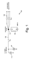
- FIG. 1 A schematic representation of a conventionally constructed motor vehicle electrical system is shown in Fig. 1.
- a generator 120, a battery 150 and a starter 110 are connected in parallel.
- the line length 130 is between the generator 120 and the starter 110 on the one hand and the battery 150 on the other hand each about 1 m.
- Starter and generator are arranged on the engine block and connected to each other via a short cable. Due to variations in the current supplied by the generator and for the transmission of the starter current, the line cross-section is approximately 25 mm 2 .
- each load circuit 160 supplies power to one or more loads.
- these lines may have a smaller cross-section than the line 130, of about 5 mm 2 .
- While the starter 110 has a very high power consumption of up to 300 A, for a short time even up to 600 A, the power consumption of all other consumers in the motor vehicle electrical system is significantly lower.
- Typical current values of consumers in the motor vehicle electrical system range from about 1.5 A for parking light of all lights, 3 A for the brake light and flashing light, 8 A for the windscreen wiper and 8.5 A for fog and headlamps over 10 A for low beam and the Interior fan of an air conditioner, 18 A for the engine control with fuel pump and 20 A for the seat heating up to an electric PTC auxiliary heater with a power consumption in the range of about 100 A.
- All load circuits 160 are protected by an overcurrent protection device against a short circuit, so that the power supply to the respective load circuit is interrupted when a short circuit occurs. This prevents thermal overheating of the cable and plug connectors in the respective load circuit.
- WO-A 02/066293 describes a two-voltage electrical system with a 14 volt battery and a 42 volt battery.
- a double-layer capacitor is used in the electrical system as the main energy storage.
- a DC-DC converter is connected between 42 volt battery and double-layer capacitor according to one embodiment.
- the double-layer capacitor is decoupled from the 42 volt battery that either only the double-layer capacitor or the battery are connected to the electrical system.
- a circuit arrangement of four switches is provided.
- US-B-6 325 035 is an electrical system for starting an internal combustion engine known.
- the energy from a low voltage battery is converted to a voltage of over 100 volts through a DC to DC converter.
- the high voltage charges a high capacity capacitor.
- US-B-6,481,406 describes a starter board network for a motor vehicle.
- the voltage of a starter battery is converted by an up-converter of a voltage between 12 and 24 volts to a higher voltage.
- the object of the invention is to provide an improved motor vehicle electrical system and an improved method for starting a motor vehicle engine.
- a motor vehicle electrical system comprising a generator, a battery, a starter and a high capacity capacitor for storing electrical energy for starting an automotive engine.
- the motor vehicle electrical system comprises a voltage converter and a breaker, which are connected in parallel between the capacitor and the battery are switched.
- the voltage converter and the breaker are controlled so that the voltage converter converts the voltage of the battery into a higher voltage and the breaker interrupts the electrical connection between the battery and the capacitor.
- a method for starting a motor vehicle engine is specified with a motor vehicle electrical system.
- the motor vehicle electrical system comprises a generator, a battery, a starter and a capacitor of high capacity for storing electrical energy for the starting process of the motor vehicle engine.
- the method detects an imminent starting operation in which the motor vehicle engine is started by means of the starter and charges the capacitor of high capacity.
- To charge the capacitor an electrical connection between the battery and the high-capacity capacitor is interrupted and the voltage of the battery is converted via a voltage converter into a higher voltage.
- the starter is supplied with energy from the high capacity capacitor.
- the activation of the voltage converter and the opening of the breaker is controlled according to the invention by a control unit.
- the voltage converter and the breaker can be driven accordingly.
- the charging of the capacitor is performed in this way a short time before the start of the boot process.
- the capacitor is charged according to the invention to a higher voltage.
- the battery voltage is converted via a voltage converter only during the charging process in a higher voltage and fed to the capacitor.
- the energy reserves available for the starting process can be increased in a simple manner. Even with a "weak" battery, the vehicle can be safely started.
- the capacitance of the capacitor can be correspondingly reduced so that the capacitor can have a lower capacitance for the same amount of stored energy.
- the voltage converter increases the battery voltage from about 12.5 V to about 16 V. With this increase in voltage, the amount of energy stored in the capacitor can be increased by about 60%.
- An increase to 16 V has the further advantage that an increase in the voltage in the electrical system by this amount does not cause any problems with other electrical components of the electrical system. A further increase in voltage, however, could affect the reliability of other components of the electrical system.
- the opened state of a vehicle door is detected when the engine is stationary, preferably the driver's door open / closed state. This leaves enough time to charge the capacitor, even with a low battery, and to allow a safe startup.
- the charging of the capacitor is performed in dependence on the position of the ignition key. Preferably either by inserting the ignition key in the ignition or in the position of the ignition key "ignition ON".
- the breaker is not closed until the engine has been successfully started or the generator is generating power.
- the voltage of the generator is monitored and the breaker is closed in dependence on the height of the generator voltage, for example when a certain voltage value is reached. This makes it easy to determine a safe starting of the engine and stop the boot process.
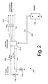
- Fig. 2 shows a schematic view of the structure of a motor vehicle electrical system according to the invention.
- a starter 110 and a generator 120 are separate Supply lines 120 connected to an electronic power distributor 210.
- a battery 150 is also connected via a supply line 240.
- the generator 120 provides electrical power to the automotive electrical system 200 during operation of the automotive engine
- the battery 150 stores the power provided by the generator 120 during operation of the engine.
- electrical energy is generated via a chemical reaction in the battery 150 and supplied to the starter 110.
- the power distributor 210 controllably switches individual load circuits 230 to the motor vehicle electrical system.
- the battery 150 can be positioned anywhere in the vehicle electrical system 200 according to the invention in the motor vehicle, without line connections must be used with large cable cross-sections.
- a feed line 130 having a length L Zul1 of approximately 1 m has a cross section of 25 mm 2
- the feed lines 220 according to the invention only have a cross-sectional area of approximately 5 mm 2 for the same length.
- the load circuits starting from the current distribution point have a cross section of 5 mm 2 for a length L Zul2 of approximately 1 m.
- the electrical connection of the battery to the power distribution point has a cross section of approximately 5 mm 2 at a maximum length L Zul3 of approximately 1 m.
- the battery is arranged with the Stromverteiltician in the rear of a motor vehicle.
- all connection lines to and from the power distribution point 140 or the battery 150 are considerably longer.
- the cable cross-sections must be increased to a larger line length with a correspondingly higher resistance one To avoid heat generation in the pipes.
- the cross section of the lines 130 conventionally increases from approximately 4 m to approximately 95 mm 2 at a length L Zul1 and the line cross section of the lines of the load circuits 160 increases to approximately 25 mm 2 at a length L Zul2 of up to approximately 5 m.
- these cross sections can be significantly reduced.
- the electronic power distributor 210 and the battery 150 are arranged spatially separated from each other.
- the buffer function exerted by a conventional battery is shifted into the electronic power distributor 210 to compensate for voltage fluctuations of the generator 120.
- all lines with a maximum length of about 1 m have a cross-section of the order of 5 mm 2 .
- a longer line connection between the electronic power distributor 210 and the battery 150 is required. Up to a length L Zul3 of about 4 m, the line cross-section is about 25 mm 2 .
- a further reduction of the line cross sections is possible depending on the respective application in that, according to the invention, an active current monitoring for controlling the fuse behavior in the current distributor 210 is carried out.
- the active monitoring of the current flowing in a load circuit 230 allows, at a certain time behavior, in particular at a rapid increase over a predetermined value, to switch off the load circuit.
- the cross-section of conventional lines is regularly designed for twice the rated current in order to cope with short current peaks in the load circuit without thermal overload of the lines can.
- the current monitoring according to the invention with the aid of a microprocessor-controlled control unit allows the overload protection more precisely at short overload peaks and the short-circuit behavior adapt. This can be reduced in a simple manner, the cross section and thus the weight and cost of the motor vehicle electrical system.
- the battery 150 is preferably arranged in the rear of the vehicle.
- the electronic power distributor 210 includes a plurality of semiconductor switches 410 which controllably connect the individual load circuits 412 to the automotive electrical system, i. turn a power supply to the individual load circuits on or off.
- Semiconductor switches with a smart power control are used in particular for such semiconductor switches.
- Such a semiconductor switch for example, the module 98 0268 of the company "International I.R. Rectifier” measures the current flowing in the switched-load circuit current. In the specified semiconductor device, a current proportional to the measured current is output via a separate connection.
- the current measured by each semiconductor switch 410 is supplied to a controller 440 of the electronic power distributor. This control, located either within or separate from the electronic power distributor 210, individually monitors the allowable current for each load circuit.
- the current value permissible for each load circuit is preferably adjustable separately for each load circuit 412 in the controller 440.
- different current levels and different "trip" characteristics are provided in the controller 440, which are separately selectable for each load circuit 412.
- the controller 440 causes the semiconductor switch 410 to break the electrical connection.
- the "intelligent" monitoring of the respective load current in the controller 440 allows to allow short overcurrents without interrupting the electrical connection to the power supply to the load circuit.
- the response can be designed individually, in particular to the function and the power requirements (and short-term overcurrent requirements) of the respective load circuit to be adjusted. Short overcurrents must be taken into account when starting a motor or when switching on lamps, auxiliary heaters, etc.
- the protection function is intended to prevent overcurrents or short circuits in the load circuits and lead to thermal overload of the cables and connectors.
- Thermal overload is caused by the energy converted, i. Current height multiplied by the time for which the overcurrent is applied. It may well be permissible to let ten times the rated current flow into a load circuit for one second without causing any damage.
- Such an overcurrent must be recognized by the controller 440 as unproblematic.
- a fuse would cause an interruption in such an overcurrent and interrupt the current irreversibly (until the fuse is replaced).
- Short-term overcurrents with a multiple value of the rated current occur, for example, when switching on an electric motor.
- the rotor When starting an electric motor, the rotor may initially be somewhat stiff or pinch, especially at low ambient temperatures.
- An overcurrent that is several times of the rated current occurs for several 100 ms.
- electric PTC auxiliary heaters which are used for heating the air blown into the motor vehicle interior, currents can occur during switching on within a time interval of about 10 seconds, which correspond to twice the rated current. Due to the extremely short-term occurrence of such overcurrents, these are unproblematic for the cables and connectors.
- a conventional fuse is usually set to a response current that is greater than twice the rated current. But such a conventional fuse would also accept a permanent overcurrent, which corresponds to 1.8 times the rated current.
- an electronic fuse according to the present invention can detect such an overcurrent and, after exceeding the time criterion, for example 10 seconds, interrupt the electrical connection.
- the respective load circuit can therefore be designed in its dimensions to the actual rated current, so that the cable cross-sections and the connector must not be able to withstand twice the rated current in the long term.
- the controller 440 can also be adapted to the current ambient temperature with the aid of an additional temperature sensor. At low ambient temperatures, higher currents may be allowed due to the improved cooling.
- the overcurrent detection and disconnection of a load circuit is therefore preferably temperature-dependent, and indeed according to a preferred embodiment of a predetermined dependence between the applicable upper current limit and the determined ambient temperature.
- the controller can also switch off a load circuit 412 as a function of an external signal. For example, faults in a load of a load circuit can be detected via separate sensors and the danger emanating from these for the motor vehicle can be prematurely avoided.
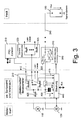
- FIG. 3 shows, by way of example only, a PTC heater 510 and a distributed power distributor 520 as consumers.
- the decentralized power distributor 520 can also switch on and off subordinate load circuits via a plurality of semiconductor switches 525. These load circuits are only examples. It is obvious to a person skilled in the art that each electrical load of a motor vehicle can be controlled directly via such a load circuit 412 or indirectly via a decentralized power distributor 520.
- a high capacity capacitor 400 is provided, which is connected in parallel to the generator 120 and the battery 150.
- the capacitor 400 has high capacitance values with low volume.
- capacities in the range of 450 to 600 F are preferably used.
- Double-layer capacitors can even reach capacities of up to several thousand F.
- Double-layer capacitors achieve a much higher energy density than aluminum electrolytic capacitors and a multiple higher power density than lead-acid batteries. While in batteries the electrical energy is stored electrochemically, the electrical energy in a capacitor is stored directly in the form of positive or negative charges on the plates of the capacitor. No chemical reaction on the electrode surfaces is required.
- Such double-layer capacitors for example double-layer capacitors from EPCOS called "UltraCap” store electrical energy and release it with high efficiency. Unlike batteries, they can be charged and discharged with very high currents without wear. In addition, they enable safe operation even at very low temperatures and low voltage values. They deliver high power without delay and very low loss with discharging currents of up to 400 A.
- the start-up process is no longer handled by the battery 150, but by the high-performance capacitor 400.
- the capacitor 400 is charged by the battery 150 prior to the start-up process. Subsequently, the capacitor 400 outputs the stored energy to the starter 110.
- the starting process can thus be made safer, since the capacitor is able to deliver high amounts of energy even at low temperatures for a short time.
- conventional vehicles often have start-up problems at low temperatures because the chemical reactions occurring in the battery 150 do not allow large currents.
- the starting behavior can be further improved by increasing the energy stored in it without increasing the capacitance of the capacitor.
- a voltage converter 310 is connected between the battery 150 and the capacitor 400 in preparation for a starting operation.
- the voltage converter 310 converts the voltage 150 supplied by the battery into a higher voltage.
- the capacitor can absorb a much larger amount of energy at the same capacity.
- a breaker 320 is connected in parallel with the voltage converter 310 in the electrical connection between the battery 150 and the capacitor 400.
- the breaker disconnects the direct electrical connection between the battery and the capacitor so that a much higher voltage can be supplied to the capacitor.
- the energy available for a starting process can be increased significantly in a simple manner. A safe starting of the motor vehicle is then still possible even with a low battery with only low energy reserves.
- the voltage converter (DC / DC converter) 310 is turned off and the electrical connection between the electric power distributor 210 and the battery 150 is made by the switch 320.
- the capacitor 400 is thus connected in parallel to the battery 150 and charged to the battery voltage U BATT .
- conventional electrical systems to a voltage of about 12.5 V, in future on-board networks to about 42 V.
- the voltage converter 310 is activated and at the same time the switch 320 is opened.
- individual load circuits are switched off via the electronic power distributor 210.
- load circuits 412 are switched off, which have a high power consumption.
- the shutdown can be made in accordance with a particular embodiment of the controller 440 also in dependence on the height of the battery voltage to ensure safe startup at low battery.
- the voltage converter now generates an output voltage which is applied to the capacitor, wherein the output voltage is above the battery voltage.
- the increased output voltage is for example 16 V.
- the voltage is thus 3.5 V above the battery voltage and charges the capacitor accordingly higher. This is also the Energy stored in the capacitor is about 60% higher than a conventional charging voltage of 12.5 V.
- the advantage achieved by the voltage converter can either be converted into increased energy reserves for the starting process or to reduce the capacitance of the capacitor. For the same amount of stored energy, then a small capacitance of the capacitor 400 is sufficient for a safe startup.
- a further increase in the amount of energy in the capacitor 400 can be achieved by a further increase in the charging voltage higher than 16 V in conventional electrical systems.
- a restriction to a charging voltage of 16 V has the advantage that this increase entails no further complications with other electrical components of the electrical system.
- Today, all electrical and electronic components of a motor vehicle electrical system are designed for a maximum operating voltage of 16 V.
- the charging voltage of the capacitor 400 is therefore preferably oriented to the design of the electrical components of the electrical system and the dielectric strength of the capacitor itself. In future on-board networks with a system voltage of 42 V, the capacitor can be charged to a much higher voltage, as far as a short-term increase in voltage of the other electrical components is tolerated without problems.
- the charging of the capacitor takes place in good time before starting the starting process.
- several triggers can be used.
- the driver may start charging when the ignition key is plugged in or the ignition switch is turned to the "ignition ON" position.
- the charging process can be triggered by opening a vehicle door.
- the opening of any vehicle door as well as the opening of the driver's vehicle door can be detected and used as a trigger signal for charging. If the vehicle door is used as a triggering event to start the recharge, there is more time available than when the ignition key position is detected.
- the voltage converter With the ignition key position "Start" the voltage converter is switched off. As long as the boot process is running, the breaker 320 remains open. Once the engine is running automatically, the breaker 320 is closed and the electrical system is set back to a voltage of about 12, 5 V.
- the capacitor 400 not only enables an improvement of the starting operation, but also can take over the buffering effect of the conventional battery 150.
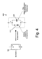
- An equivalent circuit diagram of a conventional battery 150 is shown in FIG.
- the equivalent circuit 600 of the battery 150 shows that the battery has not only the function of a chemical energy storage 610 but also the function of a buffer capacitor 620. This capacitor effect results from the internal structure of the lead-acid battery.
- the capacitor effect of a conventional battery has hitherto been used to smooth voltage fluctuations resulting from the generator 120.
- the generator 120 generates when the motor vehicle engine a three-phase current, which is rectified by means of diodes.
- the battery 150 is spatially arranged to be between the generator 150 and the loads in the load circuits 412.
- a low pass is formed from the combination of the battery capacity C Batt and the supply resistance of the electrical connection line between the generator 120 and the battery 150 R Zul1 .
- the low pass causes a smoothing of the voltage fluctuations of the current generated by the generator.
- this function is taken over by the high capacity capacitor 400.
- While conventional vehicle electrical systems are designed so that high currents can flow on the electrical connection lines between generator and battery to compensate for voltage fluctuations, according to the invention the function of energy storage and energy buffering of separate units in the motor vehicle electrical system is perceived.
- the capacitor 400 takes over the buffering of voltage fluctuations, the battery 150 provides the energy for the starting process.
- the battery can be easily positioned away from the generator and the power distributor, without the conventional effort for an electrical line connection 240 with the battery is required.
- the cross-sections can be reduced to much smaller values, as described by way of example in connection with FIG. 2.
- motor vehicle electrical systems are lighter and cheaper.
- the buffer function is achieved by the arrangement sequence generator - battery - power distribution - consumer in conjunction with the resulting low-pass filter.
- the low-pass filter is formed from the supply resistance R Zul1 between the generator and the battery on the one hand and the capacity C Batt of the battery on the other hand.
- the new motor vehicle electrical system has a number of advantages over conventional electrical systems.
- the starter battery no longer takes over the starting function, is subjected to a lower pulse and current load, only has to meet reduced requirements with regard to the low-temperature behavior and can be a battery with a reduced storage capacity. With the aid of a voltage transformer, the energy and thus the starting reliability can be increased.
- the lines have only a smaller cross section, so that costs and weight advantages are achieved, especially in the arrangement of the battery in the rear of the vehicle.
Description
Die Erfindung betrifft ein verbessertes Kraftfahrzeug-Bordnetz. Insbesondere betrifft die Erfindung ein neuartiges Kraftfahrzeug-Bordnetz, das einen zuverlässigeren Motorstart ermöglicht.The invention relates to an improved motor vehicle electrical system. In particular, the invention relates to a novel motor vehicle electrical system, which allows a more reliable engine start.
Ein Kraftfahrzeugbordnetz versorgt eine Vielzahl von Steuergeräten und Signalkomponenten in einem Kraftfahrzeug mit Strom. Der Strom wird entweder einer Batterie als Energiespeicher oder, beim Betrieb des Kraftfahrzeugmotors, einem Generator entnommen. Über Relais oder einen elektronischen Stromverteiler mit Halbleiterschaltern kann eine Vielzahl einzelner Anwendungen über individuelle Laststromkreise mit Strom aus dem Kraftfahrzeug-Bordnetz versorgt werden.A motor vehicle electrical system supplies power to a plurality of control devices and signal components in a motor vehicle. The power is taken either from a battery as energy storage or, during operation of the motor vehicle engine, a generator. Via relays or an electronic power distributor with semiconductor switches, a large number of individual applications can be supplied with power from the motor vehicle electrical system via individual load circuits.
Herkömmliche Bordnetze mit einer Spannung von 14 V basieren auf einer Batteriespannung von 12 Volt. Zukünftige Bordnetze sind mit einer 36 Volt-Batterie ausgestattet. Für eine Übergangszeit, in der eine Umstellung von einem 14 Volt auf ein 42 Volt-System stattfindet, werden beide Systeme parallel in einem Kraftfahrzeug eingesetzt.Conventional on-board electrical systems with a voltage of 14 V are based on a battery voltage of 12 volts. Future Bordnetze are equipped with a 36 volt battery. For a transitional period in which a conversion from a 14 volt to a 42 volt system takes place, both systems are used in parallel in a motor vehicle.
Eine schematische Darstellung eines konventionell aufgebauten Kraftfahrzeug-Bordnetzes ist in Fig. 1 dargestellt. In dem abgebildeten Bordnetz 100 sind ein Generator 120, eine Batterie 150 und ein Starter 110 parallel geschaltet. Im Allgemeinen beträgt die Leitungslänge 130 zwischen dem Generator 120 und dem Starter 110 einerseits und der Batterie 150 andererseits jeweils etwa 1 m. Dabei sind Starter und Generator am Motorblock angeordnet und jeweils über ein kurzes Kabel miteinander verbunden. Aufgrund von Schwankungen des vom Generator bereitgestellten Stroms und zur Übertragung des Starterstroms beträgt der Leitungsquerschnitt in etwa 25 mm2.A schematic representation of a conventionally constructed motor vehicle electrical system is shown in Fig. 1. In the depicted vehicle
Über einen herkömmlichen Stromverteilpunkt oder Stromverteiler 140 wird der Strom verschiedenen Laststromkreisen 160 im Bordnetz des Kraftfahrzeugs zugeführt. Jeder Laststromkreis 160 versorgt einen oder mehrere Verbraucher mit Strom. Bei einer Leitungslänge eines Laststromkreises von etwa 1 m können diese Leitungen einen geringeren Querschnitt als die Leitung 130 aufweisen, und zwar von ca. 5 mm2.Via a conventional power distribution point or
Während der Starter 110 eine sehr hohe Stromaufnahme von bis zu 300A, kurzzeitig sogar bis zu 600A, aufweist, ist die Stromaufnahme aller anderen Verbraucher im Kraftfahrzeug-Bordnetz deutlich geringer. Typische Stromwerte von Verbrauchern im Kraftfahrzeug-Bordnetz reichen von etwa 1,5 A für Standlicht aller Leuchten, 3 A für das Bremslicht und Blinklicht, 8 A für den Scheibenwischer und 8,5 A für Nebel- und Fernscheinwerfer über 10 A für Abblendlicht und das Innenraumgebläse einer Klimaanlage, 18 A für die Motorsteuerung mit Kraftstoffpumpe und 20 A für die Sitzheizung bis hin zu einem elektrischen PTC-Zuheizer mit einer Stromaufnahme im Bereich von etwa 100 A.While the
Alle Lastkreise 160 sind durch eine Überstromschutzeinrichtung gegen einen Kurzschluss gesichert, so dass die Stromzufuhr zu dem jeweiligen Laststromkreis unterbrochen wird, sobald ein Kurzschluss auftritt. Dadurch wird eine thermische Überhitzung der Kabel- und Steckverbinder in dem jeweiligen Lastkreis verhindert.All
Aus
Aufgabe der Erfindung ist es, ein verbessertes Kraftfahrzeug-Bordnetz und ein verbessertes Verfahren zum Starten eines Kraftfahrzeugmotors anzugeben.The object of the invention is to provide an improved motor vehicle electrical system and an improved method for starting a motor vehicle engine.
Diese Aufgabe wird mit den Merkmalen der unabhängigen Patentansprüche gelöst.This object is achieved with the features of the independent claims.
Gemäß einem ersten Aspekt der Erfindung wird ein Kraftfahrzeug-Bordnetz angegeben, das einen Generator, eine Batterie, einen Starter und einen Kondensator hoher Kapazität zur Speicherung elektrischer Energie für den Startvorgang eines Kraftfahrzeugmotors umfasst. Außerdem umfasst das Kraftfahrzeug-Bordnetz einen Spannungswandler und einen Unterbrecher, die parallel zwischen den Kondensator und die Batterie geschaltet sind. Zur Vorbereitung eines Startvorgangs des Kraftfahrzeugmotors sind der Spannungswandler und der Unterbrecher so gesteuert, dass der Spannungswandler die Spannung der Batterie in eine höhere Spannung umsetzt und der Unterbrecher die elektrische Verbindung zwischen der Batterie und dem Kondensator unterbricht.According to a first aspect of the invention, there is provided a motor vehicle electrical system comprising a generator, a battery, a starter and a high capacity capacitor for storing electrical energy for starting an automotive engine. In addition, the motor vehicle electrical system comprises a voltage converter and a breaker, which are connected in parallel between the capacitor and the battery are switched. In preparation for a starting operation of the automotive engine, the voltage converter and the breaker are controlled so that the voltage converter converts the voltage of the battery into a higher voltage and the breaker interrupts the electrical connection between the battery and the capacitor.
Gemäß einem weiteren Aspekt der Erfindung wird ein Verfahren zum Starten eines Kraftfahrzeugmotors mit einem Kraftfahrzeug-Bordnetz angegeben. Das Kraftfahrzeug-Bordnetz umfasst einen Generator, eine Batterie, einen Starter und einen Kondensator hoher Kapazität zur Speicherung elektrischer Energie für den Startvorgang des Kraftfahrzeugmotors. Das Verfahren erfasst einen kurz bevorstehenden Startvorgang, bei dem der Kraftfahrzeugmotor mit Hilfe des Starters in Betrieb gesetzt wird, und lädt den Kondensator hoher Kapazität auf. Zum Aufladen des Kondensators wird eine elektrische Verbindung zwischen der Batterie und dem Kondensator hoher Kapazität unterbrochen und die Spannung der Batterie über einen Spannungswandler in eine höhere Spannung umgesetzt. Zum Starten des Kraftfahrzeugmotors wird der Starter mit Energie aus dem Kondensator hoher Kapazität versorgt.According to a further aspect of the invention, a method for starting a motor vehicle engine is specified with a motor vehicle electrical system. The motor vehicle electrical system comprises a generator, a battery, a starter and a capacitor of high capacity for storing electrical energy for the starting process of the motor vehicle engine. The method detects an imminent starting operation in which the motor vehicle engine is started by means of the starter and charges the capacitor of high capacity. To charge the capacitor, an electrical connection between the battery and the high-capacity capacitor is interrupted and the voltage of the battery is converted via a voltage converter into a higher voltage. To start the motor vehicle engine, the starter is supplied with energy from the high capacity capacitor.
Die Aktivierung des Spannungswandlers und die Öffnung des Unterbrechers wird erfindungsgemäß von einer Steuereinheit kontrolliert. Mit Erfassung eines bevorstehenden Startvorgangs können der Spannungswandler und der Unterbrecher entsprechend angesteuert werden. Der Ladevorgang des Kondensators wird auf diese Weise eine kurze Zeit vor Beginn des Startvorgangs durchgeführt.The activation of the voltage converter and the opening of the breaker is controlled according to the invention by a control unit. Upon detection of an impending startup, the voltage converter and the breaker can be driven accordingly. The charging of the capacitor is performed in this way a short time before the start of the boot process.
Es ist der besondere Ansatz der vorliegenden Erfindung, die Startenergie zum Inbetriebsetzen des Kraftfahrzeugmotors nicht direkt aus der Batterie, sondern aus einem Kondensator hoher Kapazität bereitzustellen. Um die in dem Kondensator gespeicherte Energie für den Startvorgang zu erhöhen, ohne die Kapazität des Kondensators zu erhöhen, wird erfindungsgemäß der Kondensator auf eine höhere Spannung aufgeladen. Zu diesem Zweck wird die Batteriespannung über einen Spannungswandler nur während des Aufladevorgangs in eine höhere Spannung umgesetzt und dem Kondensator zugeführt.It is the particular approach of the present invention to provide the starting energy for starting up the automobile engine not directly from the battery but from a high capacity capacitor. To increase the energy stored in the capacitor for starting, without the capacitance of the capacitor increase, the capacitor is charged according to the invention to a higher voltage. For this purpose, the battery voltage is converted via a voltage converter only during the charging process in a higher voltage and fed to the capacitor.
Auf diese Weise lassen sich die für den Startvorgang zur Verfügung stehenden Energiereserven in einfacher Weise erhöhen. Auch bei einer "schwachen" Batterie kann das Fahrzeug sicher gestartet werden. Alternativ lässt sich die Kapazität des Kondensators entsprechend reduzieren, so dass der Kondensator bei gleicher gespeicherter Energiemenge eine geringere Kapazität aufweisen kann.In this way, the energy reserves available for the starting process can be increased in a simple manner. Even with a "weak" battery, the vehicle can be safely started. Alternatively, the capacitance of the capacitor can be correspondingly reduced so that the capacitor can have a lower capacitance for the same amount of stored energy.
Vorzugsweise erhöht der Spannungswandler die Batteriespannung von etwa 12,5 V auf etwa 16 V. Mit dieser Spannungserhöhung lässt sich die in dem Kondensator gespeicherte Energiemenge um ca. 60% erhöhen. Eine Erhöhung auf 16 V hat weiterhin den Vorteil, dass eine Erhöhung der Spannung im Bordnetz um diesen Betrag keine Probleme bei anderen elektrischen Komponenten des Bordnetzes nach sich zieht. Eine weitere Erhöhung der Spannung dagegen könnte die Betriebssicherheit anderer Komponenten des Bordnetzes beeinträchtigen.Preferably, the voltage converter increases the battery voltage from about 12.5 V to about 16 V. With this increase in voltage, the amount of energy stored in the capacitor can be increased by about 60%. An increase to 16 V has the further advantage that an increase in the voltage in the electrical system by this amount does not cause any problems with other electrical components of the electrical system. A further increase in voltage, however, could affect the reliability of other components of the electrical system.
Zur Erfassung eines kurz bevorstehenden Startvorgangs wird der geöffnete Zustand einer Fahrzeugtür bei stehendem Motor erfasst, vorzugsweise der Offen/Geschlossen-Zustand der Fahrertür. Damit bleibt ausreichend Zeit, um den Kondensator aufzuladen, auch bei einer schwachen Batterie, und einen sicheren Startvorgang zu ermöglichen.To detect an imminent starting operation, the opened state of a vehicle door is detected when the engine is stationary, preferably the driver's door open / closed state. This leaves enough time to charge the capacitor, even with a low battery, and to allow a safe startup.
Gemäß einer anderen bevorzugten Ausführungsform wird der Aufladevorgang des Kondensators in Abhängigkeit von der Stellung des Zündschlüssels durchgeführt. Vorzugsweise entweder durch Einstecken des Zündschlüssels in das Zündschloss oder bei der Stellung des Zündschlüssels "Zündung EIN".According to another preferred embodiment, the charging of the capacitor is performed in dependence on the position of the ignition key. Preferably either by inserting the ignition key in the ignition or in the position of the ignition key "ignition ON".
Vorzugsweise wird der Unterbrecher erst dann geschlossen, wenn der Motor erfolgreich gestartet wurde oder der Generator Strom erzeugt. Dazu wird vorzugsweise die Spannung des Generators überwacht und der Unterbrecher in Abhängigkeit von der Höhe der Generatorspannung geschlossen, beispielsweise bei Erreichen eines bestimmten Spannungswertes. Damit lässt sich in einfacher Weise ein sicheres Starten des Motors feststellen und der Startvorgang beenden.Preferably, the breaker is not closed until the engine has been successfully started or the generator is generating power. For this purpose, preferably the voltage of the generator is monitored and the breaker is closed in dependence on the height of the generator voltage, for example when a certain voltage value is reached. This makes it easy to determine a safe starting of the engine and stop the boot process.
Weitere vorteilhafte Ausgestaltungen sind Gegenstand der Unteransprüche.Further advantageous embodiments are the subject of the dependent claims.
Im Folgenden wird die vorliegende Erfindung anhand bevorzugter Ausführungsformen im Zusammenhang mit den beiliegenden Zeichnungen erläutert. Dabei zeigen die Zeichnungen im Einzelnen:
- Fig. 1
- den Aufbau eines herkömmlichen Kraftfahrzeug-Bordnetzes;
- Fig. 2
- den Aufbau eines erfindungsgemäßen Kraftfahrzeug-Bordnetzes;
- Fig. 3
- einen detaillierten Aufbau eines erfindungsgemäßen Kraftfahrzeug-Bordnetzes gemäß der vorliegenden Erfindung und
- Fig. 4
- eine elektrische Ersatzschaltung für eine herkömmliche Autobatterie.
- Fig. 1
- the structure of a conventional motor vehicle electrical system;
- Fig. 2
- the structure of a motor vehicle electrical system according to the invention;
- Fig. 3
- a detailed structure of a motor vehicle electrical system according to the invention according to the present invention and
- Fig. 4
- an electrical equivalent circuit for a conventional car battery.
Fig. 2 zeigt in schematischer Weise den Aufbau eines erfindungsgemäßen Kraftfahrzeug-Bordnetzes. Ein Starter 110 und ein Generator 120 sind über separate Zuleitungen 120 mit einem elektronischen Stromverteiler 210 verbunden. Mit dem elektronischen Stromverteiler ist ebenfalls eine Batterie 150 über eine Zuleitung 240 verbunden. Während der Generator 120 während des Betriebs des Kraftfahrzeugmotors elektrischen Strom dem Kraftfahrzeug-Bordnetz 200 bereitstellt, speichert die Batterie 150 während des Betriebs des Motors die von dem Generator 120 bereitgestellte Energie. Um den Motor in Betrieb zu setzen, wird über eine chemische Reaktion in der Batterie 150 elektrische Energie erzeugt und dem Starter 110 zugeführt.Fig. 2 shows a schematic view of the structure of a motor vehicle electrical system according to the invention. A
Der Stromverteiler 210 schaltet steuerbar einzelne Laststromkreise 230 an das Kraftfahrzeug-Bordnetz.The
Anders als bei herkömmlichen Kraftfahrzeug-Bordnetzen 100 kann die Batterie 150 in dem erfindungsgemäßen Bordnetz 200 beliebig im Kraftfahrzeug positioniert werden, ohne dass Leitungsverbindungen mit großen Leitungsquerschnitten verwendet werden müssen. Während bei einem herkömmlichen Bordnetz 100 gemäß Fig. 1 eine Zuleitung 130 mit einer Länge LZul1 von etwa 1 m einen Querschnitt von 25 mm2 aufweist, weisen die erfindungsgemäßen Zuleitungen 220 bei gleicher Länge nur noch eine Querschnittsfläche von in etwa 5 mm2 auf. Die von dem Stromverteilpunkt ausgehenden Laststromkreise weisen bei einer Länge LZul2 von etwa 1 m einen Querschnitt von 5 mm2 auf.Unlike conventional motor vehicle
Bei Anordnung der Batterie 150 in der Nähe des Stromverteilpunkts 140 im Motorraum weist auch die elektrische Verbindung der Batterie mit dem Stromverteilpunkt einen Querschnitt von etwa 5 mm2 bei einer Länge LZul3 von maximal etwa 1 m auf.When the
Alternativ ist die Batterie mit dem Stromverteilpunkt im Heck eines Kraftfahrzeugs angeordnet. Bei dieser Anordnung sind in einem herkömmlichen Bordnetz 100 alle Verbindungsleitungen zu und von dem Stromverteilpunkt 140 bzw. der Batterie 150 erheblich länger. Gleichzeitig müssen die Leitungsquerschnitte erhöht werden, um bei größerer Leitungslänge mit einem entsprechend höheren Widerstand eine Wärmeentwicklung in den Leitungen zu vermeiden. Aus diesem Grund vergrößert sich herkömmlicher Weise der Querschnitt der Leitungen 130 bei einer Länge LZul1 von ca. 4 m auf ungefähr 95mm2 und der Leitungsquerschnitt der Leitungen der Lastkreise 160 bei einer Länge LZul2 von bis etwa 5 m auf ungefähr 25 mm2.Alternatively, the battery is arranged with the Stromverteilpunkt in the rear of a motor vehicle. In this arrangement, in a conventional vehicle
Erfindungsgemäß können diese Querschnitte erheblich vermindert werden. Zu diesem Zweck werden der elektronische Stromverteiler 210 und die Batterie 150 räumlich voneinander getrennt angeordnet. Gleichzeitig wird die von einer herkömmlichen Batterie ausgeübte Pufferfunktion zum Ausgleich von Spannungsschwankungen des Generators 120 in den elektronischen Stromverteiler 210 verlagert. Bei dieser Anordnung können alle Leitungen bei einer Länge von maximal etwa 1 m einen Querschnitt in der Größenordnung von 5 mm2 aufweisen. Nur bei einer Anordnung der Batterie 150 im Heck eines Kraftfahrzeugs, wobei der elektronische Stromverteiler 210 im Motorraum des Kraftfahrzeugs belassen wird, ist eine längere Leitungsverbindung zwischen elektronischem Stromverteiler 210 und der Batterie 150 erforderlich. Bis zu einer Länge LZul3 von etwa von etwa 4 m beträgt der Leitungsquerschnitt etwa 25 mm2.According to the invention, these cross sections can be significantly reduced. For this purpose, the
Eine weitere Reduzierung der Leitungsquerschnitte ist in Abhängigkeit von der jeweiligen Anwendung dadurch möglich, dass erfindungsgemäß eine aktive Stromüberwachung zur Steuerung des Sicherungsverhaltens im Stromverteiler 210 durchgeführt wird. Die aktive Überwachung des in einen Lastkreis 230 fließenden Stromes erlaubt, bei einem bestimmten Zeitverhalten, insbesondere bei einer schnellen Zunahme über einen vorbestimmen Wert, den Lastkreis abzuschalten.A further reduction of the line cross sections is possible depending on the respective application in that, according to the invention, an active current monitoring for controlling the fuse behavior in the
Im Gegensatz dazu wird der Querschnitt herkömmlicher Leitungen regelmäßig auf den doppelten Nennstrom ausgelegt, um kurze Stromspitzen im Lastkreis ohne thermische Überlastung der Leitungen verkraften zu können. Die erfindungsgemäße Stromüberwachung mit Hilfe einer mikroprozessorgesteuerten Steuereinheit erlaubt, den Überlastschutz exakter an kurzen Überlastspitzen und das Kurzschlussverhalten anzupassen. Damit kann in einfacher Weise der Querschnitt und damit das Gewicht und die Kosten des Kraftfahrzeug-Bordnetzes reduziert werden.In contrast, the cross-section of conventional lines is regularly designed for twice the rated current in order to cope with short current peaks in the load circuit without thermal overload of the lines can. The current monitoring according to the invention with the aid of a microprocessor-controlled control unit allows the overload protection more precisely at short overload peaks and the short-circuit behavior adapt. This can be reduced in a simple manner, the cross section and thus the weight and cost of the motor vehicle electrical system.
Weitere Details des erfindungsgemäßen Bordnetzes sind in Fig. 3 dargestellt. Bei der in Fig. 3 dargestellten Ausführungsform ist die Batterie 150 vorzugsweise im Heck des Fahrzeugs angeordnet.Further details of the vehicle electrical system according to the invention are shown in FIG. In the embodiment shown in Fig. 3, the
Der elektronische Stromverteiler 210 enthält eine Mehrzahl von Halbleiterschaltern 410, die die einzelnen Lastkreise 412 steuerbar mit dem Kraftfahrzeug-Bordnetz verbinden, d.h. eine Stromzufuhr zu den einzelnen Lastkreisen zu- oder abschalten. Für solche Halbleiterschalter werden insbesondere Halbleiterschalter mit einer Smart-Power-Control verwendet. Ein solcher Halbleiterschalter, beispielsweise der Baustein 98 0268 der Firma "International I.R. Rectifier" misst den in den zugeschalteten Lastkreis fließenden Strom. Bei dem angegebenen Halbleiterbaustein wird ein dem gemessenen Strom proportionaler Strom über einen separaten Anschluss ausgegeben. Der von jedem Halbleiterschalter 410 gemessene Strom wird einer Steuerung 440 des elektronischen Stromverteilers zugeführt. Diese Steuerung, die entweder innerhalb des elektronischen Stromverteilers 210 oder separat davon angeordnet ist, überwacht für jeden Lastkreis individuell den zulässigen Strom.The
Der für jeden Lastkreis zulässige Stromwert ist vorzugsweise für jeden Lastkreis 412 separat in der Steuerung 440 einstellbar. Gemäß einer bevorzugten Ausführungsform sind in der Steuerung 440 unterschiedliche Stromhöhen und unterschiedliche "Auslöse"-Charakteristika vorgesehen, die für jeden Lastkreis 412 separat auswählbar sind. Sobald der für einen Lastkreis 412 gemessene Strom den für ihn festgelegten Maximalwert unter Berücksichtigung eines zulässigen Überstroms überschreitet, veranlasst die Steuerung 440, dass der Halbleiterschalter 410 die elektrische Verbindung unterbricht.The current value permissible for each load circuit is preferably adjustable separately for each
Mit einem solchen Hableiterschalter ist ein reversibler Abschaltvorgang möglich, bei dem der Lastkreis ohne Austausch beispielsweise einer Schmelzsicherung wieder in Betrieb genommen werden kann. Außerdem ermöglicht die aktive Stromüberwachung ein schnelles Ansprechen im Kurzschussfall. Sehr hohe Kurzschlussströme fließen daher nur für wenige Millisekunden. Deshalb müssen die Leitungen und Steckverbinder des jeweiligen Lastkreises nicht auf einen Kurzschlussfall ausgelegt werden, bei dem für eine deutlich längere Zeit ein hoher Strom fließt.With such a Hableiterschalter a reversible shutdown is possible in which the load circuit without replacement, for example, a fuse can be put into operation again. In addition, the active current monitoring allows a fast response in the short-firing case. Very high short-circuit currents therefore only flow for a few milliseconds. Therefore, the lines and connectors of the respective load circuit must not be designed for a short circuit, in which flows for a much longer time, a high current.
Die "intelligente" Überwachung des jeweiligen Laststroms in der Steuerung 440 erlaubt, kurze Überströme zuzulassen, ohne dass die elektrische Verbindung zur Stromzuführung zu dem Lastkreis unterbrochen wird. Das Ansprechverhalten kann dadurch individuell gestaltet werden, insbesondere an die Funktion und den Strombedarf (und kurzzeitigen Überstrombedarf) des jeweiligen Lastkreises angepasst werden. Dabei müssen kurze Überströme beim Anlauf eines Motors oder beim Einschalten von Lampen, Zuheizem usw. berücksichtigt werden.The "intelligent" monitoring of the respective load current in the
Die Schutzfunktion soll verhindern, dass Überströme bzw. Kurzschlüsse in den Laststromkreisen auftreten und zu einer thermischen Überlastung der Leitungen und Steckverbinder führen. Die thermische Überlastung wird durch die umgesetzte Energie bewirkt, d.h. Stromhöhe multipliziert mit der Zeit, für die der Überstrom anliegt. Es kann durchaus zulässig sein, für eine Sekunde den zehnfachen Nennstrom in einen Lastkreis fließen zu lassen, ohne dass eine Beschädigung auftritt. Ein solcher Überstrom muss von der Steuerung 440 als unproblematisch erkannt werden. Eine Schmelzsicherung dagegen würde bei einem solchen Überstrom eine Unterbrechung herbeiführen und den Strom irreversibel (bis zum Austausch der Sicherung) unterbrechen.The protection function is intended to prevent overcurrents or short circuits in the load circuits and lead to thermal overload of the cables and connectors. Thermal overload is caused by the energy converted, i. Current height multiplied by the time for which the overcurrent is applied. It may well be permissible to let ten times the rated current flow into a load circuit for one second without causing any damage. Such an overcurrent must be recognized by the
Kurzzeitige Überströme mit einem mehrfachen Wert des Nennstroms treten beispielsweise beim Einschalten eines Elektromotors auf. Beim Anfahren eines Elektromotors kann der Rotor anfänglich etwas schwergängig sein oder klemmen, insbesondere bei tiefen Umgebungstemperaturen. Ein Überstrom, der einem Mehrfachen des Nennstroms entspricht, tritt für einige 100 ms auf. Auch bei elektrischen PTC-Zuheizern, die zur Erwärmung der in den Kraftfahrzeuginnenraum geblasenen Luft verwendet werden, können beim Einschalten innerhalb eines Zeitintervalls von ca. 10 Sekunden Ströme auftreten, die dem Doppelten des Nennstroms entsprechen. Aufgrund des extrem kurzzeitigen Auftretens solcher Überströme sind diese für die Leitungen und Steckverbinder unproblematisch.Short-term overcurrents with a multiple value of the rated current occur, for example, when switching on an electric motor. When starting an electric motor, the rotor may initially be somewhat stiff or pinch, especially at low ambient temperatures. An overcurrent that is several times of the rated current occurs for several 100 ms. Even with electric PTC auxiliary heaters, which are used for heating the air blown into the motor vehicle interior, currents can occur during switching on within a time interval of about 10 seconds, which correspond to twice the rated current. Due to the extremely short-term occurrence of such overcurrents, these are unproblematic for the cables and connectors.
Eine herkömmliche Schmelzsicherung ist in der Regel auf einen Ansprechstrom eingestellt, der größer als das Doppelte des Nennstroms ist. Eine solche herkömmliche Sicherung würde aber auch einen dauernden Überstrom akzeptieren, der dem 1,8-fachen des Nennstroms entspricht. Im Gegensatz dazu kann eine elektronische Absicherung gemäß der vorliegenden Erfindung einen derartigen Überstrom erkennen und nach Überschreiten des Zeitkriteriums, beispielsweise 10 Sekunden, die elektrische Verbindung unterbrechen. Der jeweilige Laststromkreis kann daher in seiner Dimensionierung auf den tatsächlichen Nennstrom ausgelegt werden, so dass die Leitungsquerschnitte und der Steckverbinder nicht auf Dauer den doppelten Nennstrom aushalten können müssen.A conventional fuse is usually set to a response current that is greater than twice the rated current. But such a conventional fuse would also accept a permanent overcurrent, which corresponds to 1.8 times the rated current. In contrast, an electronic fuse according to the present invention can detect such an overcurrent and, after exceeding the time criterion, for example 10 seconds, interrupt the electrical connection. The respective load circuit can therefore be designed in its dimensions to the actual rated current, so that the cable cross-sections and the connector must not be able to withstand twice the rated current in the long term.
Die erfindungsgemäße Steuerung 440 lässt sich auch mit Hilfe eines zusätzlichen Temperatursensors an die aktuelle Umgebungstemperatur anpassen. Bei niedrigen Umgebungstemperaturen können aufgrund der verbesserten Kühlung höhere Ströme zugelassen werden. Die Überstromerkennung und Abschaltung eines Lastkreises erfolgt daher vorzugsweise temperaturabhängig, und zwar gemäß einer bevorzugten Ausführungsform über eine vorbestimmte Abhängigkeit zwischen der anzuwendenden Stromobergrenze und der ermittelten Umgebungstemperatur.The
Gemäß einer weiter vorteilhaften Ausführungsform kann die Steuerung einen Lastkreis 412 auch in Abhängigkeit von einem externen Signal abschalten. Beispielsweise können Störungen in einem Verbraucher eines Lastkreises über separate Sensoren erkannt und die von diesen ausgehenden Gefahr für das Kraftfahrzeug vorzeitig gebannt werden.According to a further advantageous embodiment, the controller can also switch off a
In Fig. 3 sind nur beispielhaft ein PTC-Zuheizer 510 und ein dezentraler Stromverteiler 520 als Verbraucher dargestellt. Der dezentrale Stromverteiler 520 kann über eine Mehrzahl von Halbleiterschaltern 525 ebenfalls untergeordnete Lastkreise zu-und abschalten. Diese Lastkreise sind nur beispielhaft. Für den Fachmann ist es selbstverständlich, dass jeder elektrische Verbraucher eines Kraftfahrzeugs über einen solchen Lastkreis 412 direkt, oder indirekt über einen dezentralen Stromverteiler 520, ansteuerbar ist.FIG. 3 shows, by way of example only, a
In dem elektrischen Stromverteiler 510 ist erfindungsgemäß ein Kondensator 400 hoher Kapazität vorgesehen, der parallel zum Generator 120 und der Batterie 150 geschaltet ist. Der Kondensator 400 besitzt hohe Kapazitätswerte bei geringem Bauvolumen. Für ein Kraftfahrzeug werden vorzugsweise Kapazitäten im Bereich von 450 bis 600 F verwendet. Heutzutage können Doppelschichtkondensatoren sogar Kapazitäten bis zu mehreren tausend F erreichen.In the
Doppelschichtkondensatoren erreichen eine um ein Vielfaches höhere Energiedichte als Aluminium-Elektrolytkondensatoren und eine mehrfach höhere Leistungsdichte als Bleibatterien. Während in Batterien die elektrische Energie elektrochemisch gespeichert wird, wird die elektrische Energie in einem Kondensator direkt in Form von positiven oder negativen Ladungen auf den Platten des Kondensators gespeichert. Dabei ist keine chemische Reaktion an den Elektrodenoberflächen erforderlich. Solche Doppelschichtkondensatoren, beispielsweise Doppelschichtkondensatoren der Firma EPCOS mit der Bezeichnung "UltraCap" speichern elektrische Energie und geben sie mit hohem Wirkungsgrad wieder ab. Im Unterschied zu Batterien können sie mit sehr hohen Strömen verschleißfrei geladen und entladen werden. Zudem ermöglichen sie eine sichere Funktion auch bei sehr niedrigen Temperaturen und niedrigen Spannungswerten. Sie geben hohe Leistungen verzögerungsfrei und sehr verlustarm bei Entladeströmen mit bis zu 400 A ab.Double-layer capacitors achieve a much higher energy density than aluminum electrolytic capacitors and a multiple higher power density than lead-acid batteries. While in batteries the electrical energy is stored electrochemically, the electrical energy in a capacitor is stored directly in the form of positive or negative charges on the plates of the capacitor. No chemical reaction on the electrode surfaces is required. Such double-layer capacitors, for example double-layer capacitors from EPCOS called "UltraCap" store electrical energy and release it with high efficiency. Unlike batteries, they can be charged and discharged with very high currents without wear. In addition, they enable safe operation even at very low temperatures and low voltage values. They deliver high power without delay and very low loss with discharging currents of up to 400 A.
Durch die Parallelschaltung eines Kondensators 400 mit hoher Kapazität zu dem Generator 120 und der Starterbatterie 51 lassen sich mehrere Vorteile erreichen. Für den Startvorgang ist nicht mehr die Batterie 150 zuständig, sondern der Hochleistungskondensator 400. Der Kondensator 400 wird vor Ausführung des Startvorgangs von der Batterie 150 aufgeladen. Anschließend gibt der Kondensator 400 die gespeicherte Energie an den Starter 110 ab. Der Startvorgang kann damit sicherer ausgestaltet werden, da der Kondensator in der Lage ist, hohe Energiemengen auch kurzzeitig bei niedrigen Temperaturen abzugeben. Im Gegensatz dazu haben herkömmliche Kraftfahrzeuge bei niedrigen Temperaturen häufig Startprobleme, da die in der Batterie 150 ablaufenden chemischen Reaktionen keine großen Ströme zulassen.By connecting a
Gemäß einer besonders vorteilhaften Ausführungsform der Erfindung lässt sich das Startverhalten weiter verbessern, indem ohne Erhöhung der Kapazität des Kondensators die in ihm gespeicherte Energie erhöht wird. Zu diesem Zweck wird erfindungsgemäß zur Vorbereitung eines Startvorgangs ein Spannungswandler 310 zwischen die Batterie 150 und den Kondensator 400 geschaltet. Der Spannungswandler 310 setzt die von der Batterie gelieferte Spannung 150 in eine höhere Spannung um. Damit kann der Kondensator bei gleicher Kapazität eine sehr viel größere Energiemenge aufnehmen. Die in dem Kondensator gespeicherte Energiemenge lässt sich gemäß der nachfolgenden Gleichung bestimmen: 
Gleichzeitig ist parallel zu dem Spannungswandler 310 in die elektrische Verbindung zwischen der Batterie 150 und dem Kondensator 400 ein Unterbrecher 320 geschaltet. Der Unterbrecher trennt die direkte elektrische Verbindung zwischen der Batterie und dem Kondensator auf, so dass dem Kondensator eine sehr viel höhere Spannung zugeführt werden kann.At the same time, a
Durch die erfindungsgemäße Vorrichtung 300 mit einem Spannungswandler und einem Unterbrecher kann die für einen Startvorgang zur Verfügung stehende Energie in einfacher Weise deutlich erhöht werden. Ein sicheres Starten des Kraftfahrzeugs ist dann auch bei schwacher Batterie mit nur noch geringen Energiereserven weiterhin möglich.By means of the
Nachfolgend wird beispielhaft ein Startvorgang beschrieben, bei dem der erfindungsgemäße Spannungswandler verwendet wird.In the following, a start procedure is described by way of example in which the voltage converter according to the invention is used.
Bei Stillstand des Kraftfahrzeugs, d.h. Motor und Zündung sind ausgeschaltet, ist der Spannungswandler (DC/DC-Wandler) 310 ausgeschaltet und die elektrische Verbindung zwischen dem elektrischen Stromverteiler 210 und der Batterie 150 wird durch den Schalter 320 hergestellt. Der Kondensator 400 ist damit parallel zur Batterie 150 geschaltet und auf die Batteriespannung UBATT aufgeladen. Bei herkömmlichen Bordnetzen auf eine Spannung von etwa 12,5 V, bei zukünftigen Bordnetzen auf etwa 42 V.At standstill of the motor vehicle, ie motor and ignition are turned off, the voltage converter (DC / DC converter) 310 is turned off and the electrical connection between the
Vor dem Startvorgang des Verbrennungsmotors wird der Spannungswandler 310 aktiviert und gleichzeitig der Schalter 320 geöffnet. Vorzugsweise werden, wenn erforderlich, über den elektronischen Stromverteiler 210 einzelne Lastkreise abgeschaltet. Insbesondere werden solche Lastkreise 412 abgeschaltet, die einen hohen Strombedarf besitzen. Die Abschaltung kann gemäß einer besonderen Ausführungsform über die Steuerung 440 auch in Abhängigkeit von der Höhe der Batteriespannung vorgenommen werden, um bei schwacher Batterie ein sicheres Starten zu gewährleisten.Before the starting process of the internal combustion engine, the
Der Spannungswandler erzeugt nun eine Ausgangsspannung, die an den Kondensator angelegt ist, wobei die Ausgangsspannung oberhalb der Batteriespannung liegt. Bei einer Batteriespannung von 12,5 V beträgt die erhöhte Ausgangsspannung beispielsweise 16 V. Die Spannung liegt damit um 3,5 V oberhalb der Batteriespannung und lädt den Kondensator entsprechend höher auf. Damit ist auch die in dem Kondenstor gespeicherte Energie um etwa 60 % höher als bei einer herkömmlichen Ladespannung von 12,5 V.The voltage converter now generates an output voltage which is applied to the capacitor, wherein the output voltage is above the battery voltage. At a battery voltage of 12.5 V, the increased output voltage is for example 16 V. The voltage is thus 3.5 V above the battery voltage and charges the capacitor accordingly higher. This is also the Energy stored in the capacitor is about 60% higher than a conventional charging voltage of 12.5 V.
Damit stehen auch bei einer schwachen Batterie mit einer Batteriespannung die unterhalb von 12,5 V liegt, ausreichend Energiereserven für den Startvorgang zur Verfügung. Wenn der Spannungswandler den Kondensator 400 immer mit einer Spannung von 16 V auflädt, steht für den Startvorgang immer die gleiche Energiemenge zur Verfügung, unabhängig von der Leistungsfähigkeit der Batterie.Thus, even with a weak battery with a battery voltage below 12.5 V, sufficient energy reserves are available for the starting process. When the voltage converter always charges the
Der durch den Spannungswandler erzielte Vorteil lässt sich entweder in erhöhte Energiereserven für den Startvorgang umsetzen oder zur Reduzierung der Kapazität des Kondensators. Bei gleicher gespeicherter Energiemenge ist dann eine geringe Kapazität des Kondensators 400 für einen sicheren Startvorgang ausreichend.The advantage achieved by the voltage converter can either be converted into increased energy reserves for the starting process or to reduce the capacitance of the capacitor. For the same amount of stored energy, then a small capacitance of the
Eine weitere Erhöhung der Energiemenge im Kondensator 400 lässt sich durch eine weitere Erhöhung der Ladespannung höher als 16 V in herkömmlichen Bordnetzen erreichen. Eine Beschränkung auf eine Ladespannung von 16 V besitzt den Vorteil, dass diese Erhöhung keine weiteren Komplikationen mit anderen elektrischen Komponenten des Bordnetzes nach sich zieht. Heutzutage sind alle elektrischen und elektronischen Komponenten eines Kraftfahrzeug-Bordnetzes auf eine Betriebsspannung von maximal 16 V ausgelegt. Die Ladespannung des Kondensators 400 ist daher vorzugsweise an der Auslegung der elektrischen Komponenten des Bordnetzes und der Spannungsfestigkeit des Kondensators selbst orientiert. Bei zukünftigen Bordnetzen mit einer Systemspannung von 42 V lässt sich der Kondensator auf eine deutlich höhere Spannung aufladen, soweit eine kurzzeitige Spannungserhöhung von den anderen elektrischen Komponenten ohne Probleme verkraftet wird.A further increase in the amount of energy in the
Alternativ kann bei besonders hohen Ausgangsspannungen des Spannungswandlers kann über ein Abschalten aller Lastkreise bzw. Verbraucher über die Halbleiterschalter 410 jede Komplikation mit anderen Bordnetz-Komponenten ausgeschlossen und ein besonderes sicherer Startvorgang realisiert werden.Alternatively, at particularly high output voltages of the voltage converter can via a shutdown of all load circuits or loads on the semiconductor switches 410 any complication with other wiring systems components excluded and a special safe startup process can be realized.
Die Aufladung des Kondensators erfolgt rechtzeitig vor Beginn des Startvorgangs. Zur Einleitung des Aufladevorgangs des Kondensators 400 können mehrere Auslöser herangezogen werden. Beispielsweise kann der Fahrer die Aufladung starten, wenn der Zündschlüssel eingesteckt wird oder das Zündschloss in die Stellung "Zündung EIN" gebracht wird. Alternativ kann der Aufladevorgang durch Öffnen einer Fahrzeugtür ausgelöst werden. Dabei kann das Öffnen einer beliebigen Fahrzeugtür als auch das Öffnen der Fahrer-Fahrzeugtür erfasst und als Auslösesignal für die Aufladung verwendet werden. Wenn die Fahrzeugtür als auslösendes Ereignis für den Beginn des Aufladevorgangs verwendet wird, steht mehr Zeit als bei Erfassung der Zündschlüsselstellung zur Verfügung.The charging of the capacitor takes place in good time before starting the starting process. To initiate the charging process of the
Mit der Zündschlüsselstellung "Starten" wird der Spannungswandler ausgeschaltet. Solange der Startvorgang läuft, bleibt der Unterbrecher 320 geöffnet. Sobald der Verbrennungsmotor selbsttätig läuft, wird der Unterbrecher 320 geschlossen und das Bordnetz wieder auf eine Spannung von ca. 12, 5 V gesetzt.With the ignition key position "Start" the voltage converter is switched off. As long as the boot process is running, the
Der Kondensator 400 ermöglicht nicht nur eine Verbesserung des Startvorgangs, sondern kann außerdem die Pufferwirkung der herkömmlichen Batterie 150 übernehmen. Ein Ersatzschaltbild einer herkömmlichen Batterie 150 ist in Fig. 4 dargestellt.The
Das Ersatzschaltbild 600 der Batterie 150 zeigt, dass die Batterie nicht nur die Funktion eines chemischen Energiespeichers 610, sondern auch die Funktion eines Pufferkondensator 620 besitzt. Diese Kondensatorwirkung ergibt sich aus dem inneren Aufbau der Bleibatterie.The
Die Kondensatorwirkung einer herkömmlichen Batterie wird bisher dazu verwendet, vom Generator 120 herrührende Spannungsschwankungen zu glätten.The capacitor effect of a conventional battery has hitherto been used to smooth voltage fluctuations resulting from the
Der Generator 120 erzeugt bei laufendem Kraftfahrzeugmotor einen Drehstrom, der mit Hilfe von Dioden gleichgerichtet wird. In heutigen Kraftfahrzeugbordnetzen ist die Batterie 150 räumlich so angeordnet, dass sie zwischen dem Generator 150 und den Verbrauchern in den Lastkreisen 412 liegt. Vor allem wird aus der Kombination der Batteriekapazität CBatt und dem Zuleitungswiderstand der elektrischen Verbindungsleitung zwischen dem Generator 120 und der Batterie 150 RZul1 ein Tiefpass gebildet. Der Tiefpass bewirkt eine Glättung der Spannungsschwankungen des vom Generator erzeugten Stroms.The
Erfindungsgemäß wird diese Funktion von dem Kondensator 400 mit hoher Kapazität übernommen.According to the invention, this function is taken over by the
Während herkömmliche Bordnetze so ausgebildet sind, dass auf den elektrischen Verbindungsleitungen zwischen Generator und Batterie hohe Ströme zum Ausgleich der Spannungsschwankungen fließen können, wird erfindungsgemäß die Funktion der Energiespeicherung und Energiepufferung von getrennten Baueinheiten in dem Kraftfahrzeug-Bordnetz wahrgenommen. Während der Kondensator 400 die Pufferung von Spannungsschwankungen übernimmt, stellt die Batterie 150 die Energie für den Startvorgang bereit. Damit lässt sich die Batterie in einfacher Weise entfernt von dem Generator und dem Stromverteiler positionieren, ohne dass der herkömmliche Aufwand für eine elektrische Leitungsverbindung 240 mit der Batterie erforderlich ist. Im Gegenteil, die Querschnitte können, wie beispielhaft im Zusammenhang mit Fig. 2 beschrieben, auf deutlich kleinere Werte reduziert werden. Damit werden Kraftfahrzeugbordnetze leichter und preisgünstiger.While conventional vehicle electrical systems are designed so that high currents can flow on the electrical connection lines between generator and battery to compensate for voltage fluctuations, according to the invention the function of energy storage and energy buffering of separate units in the motor vehicle electrical system is perceived. While the
Die Pufferfunktion wird durch die Anordnungsfolge Generator - Batterie - Stromverteiler - Verbraucher in Verbindung mit dem sich einstellenden Tiefpaß erreicht. Der Tiefpaß wird aus dem Zuleitungswiderstand RZul1 zwischen dem Generator und der Batterie einerseits und der Kapazität CBatt der Batterie andererseits gebildet. Ein geringerer Leitungsquerschnitt bewirkt zudem einen höheren Zuleitungswiderstand RZul1 und verbessert damit die Tiefpasswirkung aufgrund der Gleichung für die Zeitkonstante Tau des Tiefpasses: 
Zusammenfassend hat das erfindungsgemäße neue Kraftfahrzeug-Bordnetz eine Vielzahl von Vorteilen gegenüber herkömmlichen Bordnetzen. Die Starterbatterie übernimmt nicht mehr die Startfunktion, ist einer geringeren Impuls- und Strombelastung ausgesetzt, muss nur noch reduzierte Anforderungen hinsichtlich des Tieftemperaturverhaltens erfüllen und kann eine Batterie mit reduzierter Speicherkapazität sein. Mit Hilfe eines Spannungswandlers lässt sich die Energie und damit die Startsicherheit erhöhen. Die Leitungen weisen nur noch einen geringeren Querschnitt auf, so dass Kosten und Gewichtsvorteile erzielt werden, insbesondere bei der Anordnung der Batterie im Heck des Kraftfahrzeugs.In summary, the new motor vehicle electrical system according to the invention has a number of advantages over conventional electrical systems. The starter battery no longer takes over the starting function, is subjected to a lower pulse and current load, only has to meet reduced requirements with regard to the low-temperature behavior and can be a battery with a reduced storage capacity. With the aid of a voltage transformer, the energy and thus the starting reliability can be increased. The lines have only a smaller cross section, so that costs and weight advantages are achieved, especially in the arrangement of the battery in the rear of the vehicle.
Claims (17)
- A motor vehicle electrical system, comprising a generator (120), a battery (150), a starter (110), a high-capacity capacitor (400) for storing electric energy for the starting process of a motor vehicle engine, a voltage transformer (310) and an interrupter (320), wherein the voltage transformer (310) and the interrupter (320) are connected in parallel between the capacitor (400) and the battery (150),
characterized in that
the motor vehicle electrical system further comprising a control unit (440) which controls the voltage transformer (310) and the interrupter (320) for preparing a starting process of the motor vehicle engine to effect for a short time prior to the start of the starting process an activation of the voltage transformer (310) for transforming the voltage (UBatt) of the battery (150) into a larger voltage and an opening of the interrupter (320) for charging the capacitor (400). - A motor vehicle electrical system according to claim 1, wherein the voltage (UBatt) of the battery (150) in a charged state is within the range of approximately 12.5 V and the voltage transformer (310) increases the voltage (UBatt) of the battery (150) by several volts to preferably approximately 16 V.
- A motor vehicle electrical system according to claim 2, wherein the control unit (440) activates the voltage transformer (310) and opens the interrupter (320) in dependence on the detection of an open state of a vehicle door.
- A motor vehicle electrical system according to claim 3, wherein the control unit (440) is connected to a sensor for detecting the open/closed state of the vehicle door.
- A motor vehicle electrical system according to claim 3 or 4, wherein the control unit (440) activates the voltage transformer (310) and opens the interrupter (320) in dependence on the detection of the position of the ignition key.
- A motor vehicle electrical system according to claim 5, wherein the control unit (440) activates the voltage transformer (310) and opens the interrupter (320) upon the detection of the ignition key position "ignition ON".
- A motor vehicle electrical system according to any of claims 3 to 6, wherein the control unit (440) deactivates the voltage transformer (310) while the interrupter (320) is open, as soon as the starting process of the motor vehicle engine is initiated.
- A motor vehicle electrical system according to any of claims 3 to 7, wherein the control unit (440) closes the interrupter (320) as soon as the starting process was successfully terminated.
- A motor vehicle electrical system according to claim 8, wherein the control unit (440) monitors the voltage of the generator (120) and closes the interrupter (320) in dependence on the voltage level of the generator (120).
- A method for starting a motor vehicle engine with a motor vehicle electrical system, comprising a generator (120), a battery (150), a starter (110) and a high-capacity capacitor (400) for storing electric energy for the starting process of the motor vehicle engine, comprising the steps:detecting an imminent starting process during which the motor vehicle engine is put into operation by means of the starter (110),charging the high-capacity capacitor (400), whereinan electrical connection between the battery (150) and the high-capacity capacitor (400) is interrupted, andthe voltage (UBatt) of the battery (150) is transformed by a voltage transformer (310) into a higher voltage, andsupplying the starter (110) with energy from the high-capacity capacitor (400) for starting the motor vehicle engine.
- A method according to claim 10, wherein an open state of a vehicle door is detected for detecting an imminent starting process.
- A method according to claim 11, wherein an open state of the driver's door is detected.
- A method according to any of claims 10 to 12, wherein the position of the ignition key is detected for detecting an imminent starting process.
- A method according to claim 13, wherein the ignition key position "ignition ON" is detected.
- A method according to one of claims 10 to 14, wherein the transformation of the voltage (UBatt) of the battery (150) to a higher value is terminated as soon as the starter (110) is activated.
- A method according to any of claims 10 to 15, wherein the battery (150) is electrically connected to the generator as soon as the motor vehicle engine runs by itself.
- A method according to claim 16, wherein it is detected in dependence on the voltage level of the generator (120) whether the motor vehicle engine runs by itself.
Priority Applications (8)
| Application Number | Priority Date | Filing Date | Title |
|---|---|---|---|
| DE502004005073T DE502004005073D1 (en) | 2004-02-16 | 2004-02-16 | Motor vehicle electrical system with a voltage converter |
| EP04003412.6A EP1564862B2 (en) | 2004-02-16 | 2004-02-16 | Vehicle power grid having a voltage converter |
| ES04003412.6T ES2290564T5 (en) | 2004-02-16 | 2004-02-16 | Electrical wiring for vehicles with voltage converter |
| CNB2005800050635A CN100413177C (en) | 2004-02-16 | 2005-02-02 | Vehicle power grid having a voltage converter |
| PCT/EP2005/001043 WO2005078890A1 (en) | 2004-02-16 | 2005-02-02 | Motor vehicle supply system comprising a voltage transformer |
| US10/597,913 US20070252559A1 (en) | 2004-02-16 | 2005-02-02 | Motor Vehicle Supply System Comprising a Voltage Transformer |
| KR1020067018416A KR100870560B1 (en) | 2004-02-16 | 2005-02-02 | Motor vehicle supply system comprising a voltage transformer |
| JP2006552507A JP2007524541A (en) | 2004-02-16 | 2005-02-02 | Automotive electrical system including transformer |
Applications Claiming Priority (1)
| Application Number | Priority Date | Filing Date | Title |
|---|---|---|---|
| EP04003412.6A EP1564862B2 (en) | 2004-02-16 | 2004-02-16 | Vehicle power grid having a voltage converter |
Publications (3)
| Publication Number | Publication Date |
|---|---|
| EP1564862A1 EP1564862A1 (en) | 2005-08-17 |
| EP1564862B1 true EP1564862B1 (en) | 2007-09-26 |
| EP1564862B2 EP1564862B2 (en) | 2016-10-05 |
Family
ID=34684699
Family Applications (1)
| Application Number | Title | Priority Date | Filing Date |
|---|---|---|---|
| EP04003412.6A Expired - Fee Related EP1564862B2 (en) | 2004-02-16 | 2004-02-16 | Vehicle power grid having a voltage converter |
Country Status (8)
| Country | Link |
|---|---|
| US (1) | US20070252559A1 (en) |
| EP (1) | EP1564862B2 (en) |
| JP (1) | JP2007524541A (en) |
| KR (1) | KR100870560B1 (en) |
| CN (1) | CN100413177C (en) |
| DE (1) | DE502004005073D1 (en) |
| ES (1) | ES2290564T5 (en) |
| WO (1) | WO2005078890A1 (en) |
Cited By (1)
| Publication number | Priority date | Publication date | Assignee | Title |
|---|---|---|---|---|
| AT512132A1 (en) * | 2011-11-08 | 2013-05-15 | Avl List Gmbh | BOARD POWER SUPPLY POWER SUPPLY |
Families Citing this family (21)
| Publication number | Priority date | Publication date | Assignee | Title |
|---|---|---|---|---|
| EP2069161B1 (en) | 2006-11-06 | 2011-07-13 | Bayerische Motoren Werke Aktiengesellschaft | Method and on-board vehicle power system for predictively increasing the on-board vehicle power system voltage |
| FR2912689B1 (en) * | 2007-02-15 | 2012-02-17 | Peugeot Citroen Automobiles Sa | METHOD FOR MANAGING THE POWER SUPPLY OF AN ELECTRICAL HEATING CIRCUIT FOR THE COCKPIT OF A VEHICLE |
| FR2923551A1 (en) * | 2007-11-09 | 2009-05-15 | Peugeot Citroen Automobiles Sa | Heat engine e.g. oil engine, starting system for motor vehicle, has connection units for parallely connecting two electrical energy sources to provide electrical energy to alternator-starter to start heat engine of vehicle |
| FR2923549A1 (en) * | 2007-11-09 | 2009-05-15 | Peugeot Citroen Automobiles Sa | Heat engine e.g. oil engine, starting system for e.g. hybrid vehicle, has connection units for parallely connecting two electrical energy sources so as to provide electrical energy to starter to start heat engine of vehicle |
| FR2924536B1 (en) * | 2007-12-03 | 2009-12-11 | Peugeot Citroen Automobiles Sa | ELECTRICAL CIRCUIT OF A MOTOR VEHICLE. |
| US7963264B2 (en) * | 2008-06-25 | 2011-06-21 | GM Global Technology Operations LLC | Engine cranking system and method |
| DE102009023108A1 (en) * | 2009-05-28 | 2010-12-02 | Continental Automotive Gmbh | Voltage stabilization module for attachment at battery power distributor in motor vehicle, has inlet connection and derivative connection provided for connecting carrier device with voltage supply and electrical consumer, respectively |
| DE102010039875A1 (en) * | 2010-08-27 | 2012-03-01 | Robert Bosch Gmbh | Method and device for operating a starter of a vehicle |
| DE102010054191A1 (en) * | 2010-12-11 | 2012-06-21 | Volkswagen Ag | Motor vehicle electrical system and method for operating a motor vehicle electrical system |
| EP2469070B1 (en) | 2010-12-21 | 2014-02-19 | Eberspächer Controls GmbH & Co. KG | Limitation of the drop in starting voltage in the electrical system of a motor vehicle |
| DE102012219560B4 (en) * | 2012-10-25 | 2023-01-05 | Bayerische Motoren Werke Aktiengesellschaft | vehicle electrical system architecture |
| US20140210399A1 (en) | 2013-01-25 | 2014-07-31 | Pylon Aviation Services Llc | Portable electric power source for aircraft |
| USD820204S1 (en) | 2013-01-25 | 2018-06-12 | Aviation Battery Systems Llc | Portable ground power unit |
| JP6513516B2 (en) * | 2015-07-16 | 2019-05-15 | 古河電気工業株式会社 | Power supply and control method of power supply |
| US10012185B2 (en) * | 2016-02-15 | 2018-07-03 | Delphi Technologies Ip Limited | Fast GDCI heated air intake system |
| AU2016102104B4 (en) * | 2016-08-22 | 2017-06-29 | Dc Solutions Australia Pty Ltd | Apparatus for starting an electrically cranked engine |
| US10819132B2 (en) | 2017-08-04 | 2020-10-27 | Deltran Operations Usa, Inc. | Device with battery charger system and engine start system formed from high frequency transformers |
| EP3981980A4 (en) * | 2020-08-20 | 2022-04-13 | Shenzhen Carku Technology Co., Limited | Ignition overcurrent protection device, startup power supply device, and ignition overcurrent protection method |
| DE102021112684A1 (en) * | 2021-05-17 | 2022-11-17 | Leoni Bordnetz-Systeme Gmbh | Fuse arrangement for a vehicle electrical system |
| US11685323B2 (en) | 2021-08-31 | 2023-06-27 | Zhejiang CFMOTO Power Co., Ltd. | Off-road vehicle |
| CN114655147B (en) * | 2022-05-05 | 2022-08-23 | 浙江春风动力股份有限公司 | All-terrain vehicle |
Family Cites Families (7)
| Publication number | Priority date | Publication date | Assignee | Title |
|---|---|---|---|---|
| JPH02259277A (en) * | 1989-03-31 | 1990-10-22 | Isuzu Motors Ltd | Engine starter device |
| DE19709298C2 (en) * | 1997-03-06 | 1999-03-11 | Isad Electronic Sys Gmbh & Co | Starter systems for an internal combustion engine and method for starting an internal combustion engine |
| DE19840819C1 (en) * | 1998-09-07 | 2000-08-03 | Isad Electronic Sys Gmbh & Co | Starter system for an internal combustion engine and method for starting an internal combustion engine |
| US6325035B1 (en) * | 1999-09-30 | 2001-12-04 | Caterpillar Inc. | Method and apparatus for starting an engine using capacitor supplied voltage |
| JP4550363B2 (en) * | 2001-02-16 | 2010-09-22 | シーメンス アクチエンゲゼルシヤフト | Automotive electrical system |
| JP3896258B2 (en) * | 2001-04-25 | 2007-03-22 | 株式会社日立製作所 | Automotive power supply |
| JP3988618B2 (en) * | 2002-10-30 | 2007-10-10 | 株式会社デンソー | Vehicle remote control device |
-
2004
- 2004-02-16 EP EP04003412.6A patent/EP1564862B2/en not_active Expired - Fee Related
- 2004-02-16 DE DE502004005073T patent/DE502004005073D1/en not_active Expired - Lifetime
- 2004-02-16 ES ES04003412.6T patent/ES2290564T5/en not_active Expired - Lifetime
-
2005
- 2005-02-02 JP JP2006552507A patent/JP2007524541A/en active Pending
- 2005-02-02 CN CNB2005800050635A patent/CN100413177C/en not_active Expired - Fee Related
- 2005-02-02 US US10/597,913 patent/US20070252559A1/en not_active Abandoned
- 2005-02-02 KR KR1020067018416A patent/KR100870560B1/en not_active IP Right Cessation
- 2005-02-02 WO PCT/EP2005/001043 patent/WO2005078890A1/en active Application Filing
Cited By (2)
| Publication number | Priority date | Publication date | Assignee | Title |
|---|---|---|---|---|
| AT512132A1 (en) * | 2011-11-08 | 2013-05-15 | Avl List Gmbh | BOARD POWER SUPPLY POWER SUPPLY |
| AT512132B1 (en) * | 2011-11-08 | 2016-01-15 | Avl List Gmbh | BOARD POWER SUPPLY POWER SUPPLY |
Also Published As
| Publication number | Publication date |
|---|---|
| WO2005078890A1 (en) | 2005-08-25 |
| ES2290564T5 (en) | 2017-04-24 |
| ES2290564T3 (en) | 2008-02-16 |
| CN1918767A (en) | 2007-02-21 |
| US20070252559A1 (en) | 2007-11-01 |
| DE502004005073D1 (en) | 2007-11-08 |
| EP1564862B2 (en) | 2016-10-05 |
| EP1564862A1 (en) | 2005-08-17 |
| CN100413177C (en) | 2008-08-20 |
| JP2007524541A (en) | 2007-08-30 |
| KR100870560B1 (en) | 2008-11-27 |
| KR20070009998A (en) | 2007-01-19 |
Similar Documents
| Publication | Publication Date | Title |
|---|---|---|
| EP1564862B1 (en) | Vehicle power grid having a voltage converter | |
| EP1600337B1 (en) | Electronic circuit breaker for battery | |
| DE102017203851B4 (en) | Electrical fuse, method of operating an electrical fuse and electric traction network | |
| EP2232672B1 (en) | Circuit for voltage stabilization in an onboard power supply | |
| DE19954306B4 (en) | Device for generating electrical energy with a fuel cell in a vehicle and method for operating such a device | |
| DE102014203030B4 (en) | Method for the controlled connection of several on-board network branches of a vehicle, control unit for executing the method and vehicle on-board network | |
| EP2670630B1 (en) | Device and method for stabilising voltage applied to a first electric consumer arranged in a vehicle electrical system | |
| EP3022433B1 (en) | Switch arrangement in motor vehicle electrical circuit | |
| EP3022432B1 (en) | Electronic safety interruptor for motor vehicles | |
| EP2356731A1 (en) | Vehicle having a power supply device for an electric motor and method for supplying power to said electric motor | |
| WO2014086651A2 (en) | Method for the controlled connection of a plurality of on-board power system branches of a vehicle, control unit for carrying out the method and on-board power system | |
| WO2005078891A1 (en) | Motor vehicle supply system featuring battery-independent buffering of the generator current | |
| WO2009059852A2 (en) | Starting method for hybrid drives | |
| WO2013160031A1 (en) | Motor vehicle onboard power supply system having at least two subnetworks | |
| EP3720733B1 (en) | Method for controlling an electrical system of an electrically drivable motor vehicle having a plurality of batteries, and electrical system of an electrically drivable motor vehicle | |
| WO1998039566A1 (en) | Auxiliary starting device for a diesel engine and method for starting a diesel engine | |
| EP2840253B1 (en) | On-board electrical system of a motor vehicle and vehicle with such an on-board electrical system | |
| EP1564077A1 (en) | Electronic current distributor for vehicle power supplies | |
| EP1044852B1 (en) | Power supply network for vehicles | |
| EP2394050A1 (en) | Jump start system for a vehicle | |
| WO2013182385A1 (en) | Motor vehicle electrical system having an electric machine and at least two energy stores having different charging voltages, and method for operating said motor vehicle electrical system | |
| WO2016128375A1 (en) | Method for controlling a load of a low-voltage vehicle electrical system | |
| DE102013017162B4 (en) | Switch system for motor vehicle electrical system and method for driving such a switch system | |
| DE102013016093B4 (en) | Method for controlling a pyro fuse in a motor vehicle and motor vehicle | |
| EP3327745A1 (en) | Electric fuse, method for operating an electric fuse and electrical traction network |
Legal Events
| Date | Code | Title | Description |
|---|---|---|---|
| PUAI | Public reference made under article 153(3) epc to a published international application that has entered the european phase |
Free format text: ORIGINAL CODE: 0009012 |
|
| AK | Designated contracting states |
Kind code of ref document: A1 Designated state(s): AT BE BG CH CY CZ DE DK EE ES FI FR GB GR HU IE IT LI LU MC NL PT RO SE SI SK TR |
|
| AX | Request for extension of the european patent |
Extension state: AL LT LV MK |
|
| 17P | Request for examination filed |
Effective date: 20060210 |
|
| AKX | Designation fees paid |
Designated state(s): DE ES FR IT SE |
|
| GRAP | Despatch of communication of intention to grant a patent |
Free format text: ORIGINAL CODE: EPIDOSNIGR1 |
|
| RIN1 | Information on inventor provided before grant (corrected) |
Inventor name: UHL, GUENTER, DR.-ING. |
|
| GRAS | Grant fee paid |
Free format text: ORIGINAL CODE: EPIDOSNIGR3 |
|
| GRAA | (expected) grant |
Free format text: ORIGINAL CODE: 0009210 |
|
| AK | Designated contracting states |
Kind code of ref document: B1 Designated state(s): DE ES FR IT SE |
|
| REF | Corresponds to: |
Ref document number: 502004005073 Country of ref document: DE Date of ref document: 20071108 Kind code of ref document: P |
|
| REG | Reference to a national code |
Ref country code: ES Ref legal event code: FG2A Ref document number: 2290564 Country of ref document: ES Kind code of ref document: T3 |
|
| ET | Fr: translation filed | ||
| PG25 | Lapsed in a contracting state [announced via postgrant information from national office to epo] |
Ref country code: SE Free format text: LAPSE BECAUSE OF FAILURE TO SUBMIT A TRANSLATION OF THE DESCRIPTION OR TO PAY THE FEE WITHIN THE PRESCRIBED TIME-LIMIT Effective date: 20071226 |
|
| PLBI | Opposition filed |
Free format text: ORIGINAL CODE: 0009260 |
|
| 26 | Opposition filed |
Opponent name: BERU AG Effective date: 20080626 |
|
| PLAX | Notice of opposition and request to file observation + time limit sent |
Free format text: ORIGINAL CODE: EPIDOSNOBS2 |
|
| PLBB | Reply of patent proprietor to notice(s) of opposition received |
Free format text: ORIGINAL CODE: EPIDOSNOBS3 |
|
| PLAB | Opposition data, opponent's data or that of the opponent's representative modified |
Free format text: ORIGINAL CODE: 0009299OPPO |
|
| R26 | Opposition filed (corrected) |
Opponent name: BERU AG Effective date: 20080626 |
|
| PLCK | Communication despatched that opposition was rejected |
Free format text: ORIGINAL CODE: EPIDOSNREJ1 |
|
| PLAB | Opposition data, opponent's data or that of the opponent's representative modified |
Free format text: ORIGINAL CODE: 0009299OPPO |
|
| APAH | Appeal reference modified |
Free format text: ORIGINAL CODE: EPIDOSCREFNO |
|
| APBM | Appeal reference recorded |
Free format text: ORIGINAL CODE: EPIDOSNREFNO |
|
| APBP | Date of receipt of notice of appeal recorded |
Free format text: ORIGINAL CODE: EPIDOSNNOA2O |
|
| R26 | Opposition filed (corrected) |
Opponent name: BORGWARNER BERU SYSTEMS GMBH Effective date: 20080626 |
|
| APBQ | Date of receipt of statement of grounds of appeal recorded |
Free format text: ORIGINAL CODE: EPIDOSNNOA3O |
|
| APBU | Appeal procedure closed |
Free format text: ORIGINAL CODE: EPIDOSNNOA9O |
|
| REG | Reference to a national code |
Ref country code: FR Ref legal event code: PLFP Year of fee payment: 13 |
|
| PGFP | Annual fee paid to national office [announced via postgrant information from national office to epo] |
Ref country code: DE Payment date: 20160218 Year of fee payment: 13 Ref country code: ES Payment date: 20160223 Year of fee payment: 13 |
|
| PGFP | Annual fee paid to national office [announced via postgrant information from national office to epo] |
Ref country code: FR Payment date: 20160222 Year of fee payment: 13 |
|
| PUAH | Patent maintained in amended form |
Free format text: ORIGINAL CODE: 0009272 |
|
| STAA | Information on the status of an ep patent application or granted ep patent |
Free format text: STATUS: PATENT MAINTAINED AS AMENDED |
|
| REG | Reference to a national code |
Ref country code: DE Ref legal event code: R082 Ref document number: 502004005073 Country of ref document: DE Representative=s name: GRUENECKER PATENT- UND RECHTSANWAELTE PARTG MB, DE Ref country code: DE Ref legal event code: R081 Ref document number: 502004005073 Country of ref document: DE Owner name: EBERSPAECHER CONTROLS LANDAU GMBH & CO. KG, DE Free format text: FORMER OWNER: CATEM DEVELEC GMBH, 76863 HERXHEIM, DE |
|
| 27A | Patent maintained in amended form |
Effective date: 20161005 |
|
| AK | Designated contracting states |
Kind code of ref document: B2 Designated state(s): DE ES FR IT SE |
|
| REG | Reference to a national code |
Ref country code: DE Ref legal event code: R102 Ref document number: 502004005073 Country of ref document: DE |
|
| REG | Reference to a national code |
Ref country code: ES Ref legal event code: PC2A Owner name: EBERSPAECHER CONTROLS LANDAU GMBH & CO. KG Effective date: 20161122 |
|
| REG | Reference to a national code |
Ref country code: FR Ref legal event code: CA Effective date: 20161208 Ref country code: FR Ref legal event code: CD Owner name: EBERSPACHER CONTROLS LANDAU GMBH & CO. KG, DE Effective date: 20161208 Ref country code: FR Ref legal event code: CJ Effective date: 20161208 |
|
| REG | Reference to a national code |
Ref country code: ES Ref legal event code: DC2A Ref document number: 2290564 Country of ref document: ES Kind code of ref document: T5 Effective date: 20170424 |
|
| PGFP | Annual fee paid to national office [announced via postgrant information from national office to epo] |
Ref country code: IT Payment date: 20170217 Year of fee payment: 14 |
|
| REG | Reference to a national code |
Ref country code: DE Ref legal event code: R119 Ref document number: 502004005073 Country of ref document: DE |
|
| REG | Reference to a national code |
Ref country code: FR Ref legal event code: ST Effective date: 20171031 |
|
| PG25 | Lapsed in a contracting state [announced via postgrant information from national office to epo] |
Ref country code: FR Free format text: LAPSE BECAUSE OF NON-PAYMENT OF DUE FEES Effective date: 20170228 Ref country code: DE Free format text: LAPSE BECAUSE OF NON-PAYMENT OF DUE FEES Effective date: 20170901 |
|
| REG | Reference to a national code |
Ref country code: ES Ref legal event code: FD2A Effective date: 20180629 |
|
| PG25 | Lapsed in a contracting state [announced via postgrant information from national office to epo] |
Ref country code: ES Free format text: LAPSE BECAUSE OF NON-PAYMENT OF DUE FEES Effective date: 20170217 |
|
| PG25 | Lapsed in a contracting state [announced via postgrant information from national office to epo] |
Ref country code: IT Free format text: LAPSE BECAUSE OF NON-PAYMENT OF DUE FEES Effective date: 20180216 |