EP1564718B1 - Snare strainer - Google Patents
Snare strainer Download PDFInfo
- Publication number
- EP1564718B1 EP1564718B1 EP05003030A EP05003030A EP1564718B1 EP 1564718 B1 EP1564718 B1 EP 1564718B1 EP 05003030 A EP05003030 A EP 05003030A EP 05003030 A EP05003030 A EP 05003030A EP 1564718 B1 EP1564718 B1 EP 1564718B1
- Authority
- EP
- European Patent Office
- Prior art keywords
- snare
- strainer
- stretching
- drumhead
- interconnection
- Prior art date
- Legal status (The legal status is an assumption and is not a legal conclusion. Google has not performed a legal analysis and makes no representation as to the accuracy of the status listed.)
- Not-in-force
Links
- 241000208967 Polygala cruciata Species 0.000 claims description 56
- 230000002093 peripheral effect Effects 0.000 claims description 3
- 230000000712 assembly Effects 0.000 description 3
- 238000000429 assembly Methods 0.000 description 3
- 238000005452 bending Methods 0.000 description 2
- 230000007423 decrease Effects 0.000 description 2
- 230000000694 effects Effects 0.000 description 2
- 239000002184 metal Substances 0.000 description 2
- 239000003086 colorant Substances 0.000 description 1
- 230000001419 dependent effect Effects 0.000 description 1
- 238000004519 manufacturing process Methods 0.000 description 1
- 239000013598 vector Substances 0.000 description 1
Images

Classifications
-
- G—PHYSICS
- G10—MUSICAL INSTRUMENTS; ACOUSTICS
- G10D—STRINGED MUSICAL INSTRUMENTS; WIND MUSICAL INSTRUMENTS; ACCORDIONS OR CONCERTINAS; PERCUSSION MUSICAL INSTRUMENTS; AEOLIAN HARPS; SINGING-FLAME MUSICAL INSTRUMENTS; MUSICAL INSTRUMENTS NOT OTHERWISE PROVIDED FOR
- G10D13/00—Percussion musical instruments; Details or accessories therefor
- G10D13/01—General design of percussion musical instruments
- G10D13/02—Drums; Tambourines with drumheads
-
- G—PHYSICS
- G10—MUSICAL INSTRUMENTS; ACOUSTICS
- G10D—STRINGED MUSICAL INSTRUMENTS; WIND MUSICAL INSTRUMENTS; ACCORDIONS OR CONCERTINAS; PERCUSSION MUSICAL INSTRUMENTS; AEOLIAN HARPS; SINGING-FLAME MUSICAL INSTRUMENTS; MUSICAL INSTRUMENTS NOT OTHERWISE PROVIDED FOR
- G10D13/00—Percussion musical instruments; Details or accessories therefor
- G10D13/10—Details of, or accessories for, percussion musical instruments
- G10D13/18—Snares; Snare-strainers
Definitions
- This invention relates to snare strainers that control snare assemblies (including snares) to move in close contact with or apart from drumheads.
- Snare drums produce special sound effects called tumbling effects, wherein snare assemblies each corresponding to a plurality of fine snares are controlled to move in close contact with or apart from bottom-side drumheads (corresponding to non-striking sides of snare drums), or they are controlled to move in close contact with or apart from both of bottom-side drumheads and top-side drumheads (corresponding to striking sides of snare drums), so that vibrations of drumheads are transmitted to snares to produce pattering or rattling sounds having light tone colors.
- the following documents teach adjustments of snares adapted to snare drums.
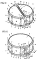
- FIG. 10 is a perspective view showing the exterior appearance of a snare drum equipped with a snare assembly in relation to a bottom-side drumhead; and FIG. 11 is a perspective view showing the exterior appearance of the snare drum viewed from the top-side drumhead thereof.
- Reference numeral 1 designates a snare drum
- reference numeral 2 designates a drum shell, i.e., a drum cylinder having openings at both ends
- reference numeral 3 designates a bottom-side drumhead covering the bottom-side opening of the drum cylinder 2
- reference numeral 4 designates a top-side drumhead covering the top-side opening of the drum cylinder 2
- reference numerals 5 designate hoops (or clamp frames) engaging with the peripheries of the openings of the drum cylinder 2
- reference numerals 6 designate lugs
- reference numerals 7 designate bolts for interconnecting the hoops 5 and the lugs 6 together
- reference numeral 8 designates a snare assembly (i.e., snares) attached in relation to the bottom-side drumhead 3
- reference numeral 9 designates a first strainer for holding a movable end 8A of the snare assembly 8
- reference numeral 10 designates a second strainer for holding a
- the snare assembly 8 includes a plurality of fine snares 11 that are arranged in parallel with each other in the longitudinal direction with prescribed distances therebetween, a pair of snare mounting plates 12 that are respectively soldered to both ends of the snares 11, and a pair of snare connection members having flexibility that are respectively attached to the snare mounting plates 12.
- the snare connection members 13 constituted by belts are pressed by pressure plates 14 and 26 and are detachably attached to the first strainer 9 and the second strainer 10 respectively.
- the snare mounting plates 12 are arranged inside of the hoop 5 to come in close contact with the bottom-side drumhead 3 together with the snares 11.
- This snare assembly 8 is referred to as an internal contact type snare assembly.
- a full contact type snare assembly is designed such that the ends of snares 11 and the snare mounting plates 12 are arranged outside of the hoop 5.
- the first strainer 9 controls the movable end 8A of the snare assembly 8 to move in close contact with or apart from the bottom-side drumhead 3.
- the first strainer 9 is constituted by a fixed base 15 that is fixed to a prescribed position on the exterior circumferential surface of the drum cylinder 2, a moving base 16 that can be freely moved with respect to the fixed base 15 in vertical directions A and B, a switch mechanism 17 that switches over the vertical movement of the moving base 16 with respect to the fixed base 15 so as to control the movable end 8A of the snare assembly 8 to move in close contact with or apart from the bottom-side drumhead 3, and a tension adjustment screw 18 that controls the vertical movement of the moving base 16 with respect to the fixed base 15 so as to perform fine adjustment on the tension applied to the snare assembly 8.
- the snare connection member 13 is tightly held between the pressure plate 14 and the moving base 16, wherein the pressure plate 14 is fixed to the moving base 16 by means of two square-headed bolts 19.
- the switch mechanism 17 includes an operation lever 20 whose rotation is converted into a linear motion by means of a link or a cam (not shown) and is transmitted to the moving base 16.
- an operation lever 20 whose rotation is converted into a linear motion by means of a link or a cam (not shown) and is transmitted to the moving base 16.
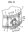
- two types of operations can be adapted to the operation lever 20, wherein in the case of FIG. 11 , thc operation lever 20 is moved in circumferential directions C and D along the exterior circumferential surface of the drum cylinder 2, and in the case of FIG. 12 , the operation lever 20 is moved in diameter directions E and F perpendicular to the exterior circumferential surface of the drum cylinder 2.
- the second strainer 10 is constituted by a fixed base 23 that is fixed to a prescribed position on the exterior circumferential surface of the drum cylinder 2, a moving base 24 that can be vertically moved with respect to the fixed base 23, and a tension adjustment screw 25 that controls the vertical movement of the moving base 24 so as to perform fine adjustment on the tension applied to the snare assembly 8.
- the snare connection member 13 attached to the fixed end 8B of the snare assembly 8 is tightly held between the moving base 24 and the pressure plate 26.
- the switch mechanism 17 of the first strainer 9 is controlled to move the moving base 16 forward in the direction A, whereby the tension applied to the snares 11 of the snare assembly 8 is reduced so that both the snares 11 and the snare mounting plate 12 move apart from the bottom-side drumhead 3.
- the switch mechanism 17 is controlled to move the moving base 16 backward in the direction B, whereby the snare connection member 13 is stretched so as to increase the tension of the snares 11, so that both the snares 11 and the snare mounting plate 12 move in close contact with the bottom-side drumhead 3.
- the first strainer 9 is designed such that the snare connection member 13 is fixed onto the moving base 16.
- the first strainer 9 requires a specific mechanism for moving the moving base 16, wherein the rotary motion of the operation lever 20 is converted into the linear motion by means of a link or a cam and is then transmitted to the moving base 16. This requires an appropriate clearance allowing smooth sliding movement between the fixed base 15 and the moving base 16, which in turn causes a problem in that when the moving base 16 slides to move vertically during drum playing, the moving base 16 may easily rattle and produce noise.
- the aforementioned problem may be solved by minimizing the clearance so as to prevent the moving base 16 from rattling.
- this requires strict dimensional tolerance and therefore increases the manufacturing cost.
- this may cause a relatively large friction when the moving base 16 is slid to move vertically; hence, it becomes difficult to smoothly move the moving base 16.
- FIGS. 1 to 7 A snare strainer according to a preferred embodiment of the invention will be described in detail with reference to FIGS. 1 to 7 , wherein parts identical to those shown in FIGS. 10 to 12 are designated by the same reference numerals; hence, the detailed description thereof will be omitted as necessary.
- FIG. 1 is a front view showing a first strainer that is placed in an ON state allowing a snare assembly to move in close contact with a bottom-side drumhead of a snare drum;
- FIG. 2 is a side view partly in cross section showing the first strainer in the ON state;
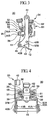
- FIG. 3 is an enlarged side view of the first strainer in the ON state, which is viewed from the right side in FIG 1 ;
- FIG. 4 is an enlarged rear view of the first strainer in the ON state;
- FIG. 5 is an enlarged view showing essential parts of the first strainer in the ON state;
- FIG. 1 is a front view showing a first strainer that is placed in an ON state allowing a snare assembly to move in close contact with a bottom-side drumhead of a snare drum;
- FIG. 2 is a side view partly in cross section showing the first strainer in the ON state;
- FIG. 3 is an enlarged side view of the first strainer in the ON state, which
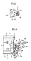
- FIG. 6 is a side view partly in cross section showing the first strainer in an OFF state allowing the snare assembly to move apart from the bottom-side drumhead of the snare drum; and
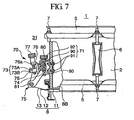
- FIG. 7 is a side view partly in cross section showing a second strainer in the ON state allowing the snare assembly to move in close contact with the bottom-side drumhead of the snare drum.
- a first strainer 30 and a second strainer 31 are respectively attached to opposite positions on the exterior circumferential surface of a drum cylinder 2 of a snare drum 1, wherein they are assembled together to form a snare strainer that controls a snare assembly 8 to move in close contact with or apart from a bottom-side drumhead 3 of the snare drum 1.
- the snare assembly 8 is constituted by a plurality of fine snares 11 that are arranged in parallel with each other with prescribed distances therebetween, a pair of snare mounting plates 12 that are respectively soldered to both ends of the snares 11, and snare connection members 13 corresponding to wires or strings that are respectively attached to the snare mounting plates 12.
- the snare assembly 8 is of a full contact type in which both ends of the snares 11 and the snare mounting plates 12 are arranged outside of a hoop 5.
- the snare connection members 13 are held by holding members 35 and 73 included the first strainer 30 and the second strainer 31 respectively.
- the first strainer 30 includes a snare stretching member 33 and a fixed base 34, which fixes the snare stretching member 33 to the exterior circumferential surface of the drum cylinder 2.
- the snare stretching member 33 is constituted by the holding member 35 for holding the snare connection member 13 attached to one end '8A' of the snare assembly 8, an interconnection member 36 (see FIG. 4 ) interconnected with the fixed base 34, and a pair of arms 37A and 37B respectively fixed to both sides of the interconnection member 36.
- the holding member 35 is constituted by a pair of a first holding member 35A and a second holding member 35B that are combined together to tightly hold the end portion of the snare connection member 13 and are integrally connected together via screws 38.
- the interconnection member 36 is formed in a block-like shape in which an internally threaded hole is formed at the center position to vertically penetrate thercthrough, whereby it is attached to the fixed base 34, and it can be vertically moved by means of a height adjustment screw 62.
- the arms 37A and 37B are shaped symmetrically to each other, and the front ends thereof are fixed to both sides of the interconnection member 36 via screws 39.
- a pair of levers 40A and 40B are attached to the arms 37A and 37B in a free rotation manner.
- the rear ends of the arms 37A and 37B have slopes 43, which are arranged opposite to the exterior circumferential surface of the drum cylinder 2 and are respectively inclined by prescribed angles relative to the exterior circumferential surface of the drum cylinder 2.
- the 'left-side' lever 40A has a shorter length compared with the 'right-side' lever 40B, wherein the front end thereof is supported by the rear end of the arm 37A to freely rotate about a rotation axis 41A.
- the right-side lever 40B is sufficiently elongated in length compared with the left-side arm 40A, wherein the front end thereof is extended forwards in proximity to the fixed base 34.
- a knob 42 is fixed to the front end of the lever 40B so as to form a switch lever (designated by the reference numeral 40B), which switches over the snare assembly 8 to move in close contact with or apart from the bottom-side drumhead 3.
- a switch lever designated by the reference numeral 40B
- the switch lever 40B is formed roughly in an L-shape in side view, the center of which matches a rotation axis 41B.
- the rear end of the switch lever 40B is inclined relative to the exterior circumferential surface of the drum cylinder 2 and is elongated in a direction departing from the exterior circumferential surface of the drum cylinder 2, wherein the center of the bent portion of the switch lever 40B is supported by the rear end of the arm 37B in a free rotation manner about the rotation axis 41B. Both the rotation axes 41 A and 41B match each other in line.
- a stretching rod 45 for supporting a portion between the holding member 35 and an outer peripheral end of the drumhead of the snare connection member 13 is bridged between the rear ends of the levers 40A and 40B.
- the stretching rod 45 comes in close contact with the front ends of the slopes 43 of the arms 37A and 37B.
- the resultant (i.e., the sum of vectors) F of the tension applied to the snare assembly 13 is directed upwardly compared with the axial line of the lever 40A, so that the switch lever 40B is maintained in the ON state.
- the stretching rod 45 slightly descends down and moves closer to the exterior circumferential surface of the drum cylinder 2, so that it comes in contact with the rear end of the slope 43. That is, the front ends and rear ends of the slopes 43 of the arms 37A and 37B function as stoppers for stopping the stretching rod 45 at an ON position and an OFF position respectively.
- O-rings 46 are attached to both ends of the stretching rod 45, which comes in contact with the slopes 43 of the arms 37A and 37B, in order to avoid the occurrence of noise.
- the function of the switch lever 40B can be realized by partially modifying the stretching rod 45 to be elongated outside of the arm 37B so that the elongated portion thereof serves as a switch knob.
- fixing portions that are outwardly bent and foldcd are respectively attached to the front ends of the arms 37A and 37B.
- a bracket 50 that is roughly bent in an L-shape is fixed onto the fixing portions 48 via screws 51.
- the holding member 35 is attached onto the upper surface of the bracket 50, wherein the holding member 35 and the bracket 50 are interconnected together by means of a tension adjuster 52, which is used to adjust the tension applied to the snare connection member 13 and is constituted by a screw having a knob.
- the tension adjuster 52 is inserted into a leading wall 50a, which is formed at the front end of the bracket 50, in a free rotation manner but is not allowed to be vertically moved, wherein it is engaged with an internally threaded hole formed at the center of the first holding member 35A. That is, when the tension adjuster 52 is rotated, the first holding member (in other words, the holding member 35) moves upwards or downwards along the surface of the bracket 50.
- This allows the snare assembly 8 to be expanded or contracted in the length direction thereof while the snare assembly 8 is fixedly set in close contact with the bottom-side drumhead 3.
- the fixed base 34 is constituted by a fixing member 60 that is formed by bending work using a metal plate and, a plurality of screws 61 for fixing the fixing member 60 onto the circumferential wall of the drum cylinder 2, and a height adjuster 62 for interconnecting the interconnection member 36 with the fixing member 60, wherein the fixing member 60 is formed in a rectangular shape in side view, both sides of which are opened.
- the height adjuster 62 adjusts the vertical height of the stretching rod 45. Similar to the tension adjuster 52, the height adjuster 62 is constituted by a screw having a knob.
- the height adjuster 62 is inserted into through holes, which are formed to penetrate through the upper and lower portions of the fixing member 60, in a free rotation manner but is not allowed to be vertically moved, wherein it is engaged with an internally threaded hole formed in the interconnection member 36.
- the interconnection member 36 moves upwards or downwards along the height adjuster 62.
- the second strainer 31 includes a snare stretching member 70 and a fixed base 71 for fixing the snare stretching member 70 onto the exterior circumferential surface of the drum cylinder 2.
- the snare stretching member 70 is constituted by a holding member 73 for holding the snare connection member 13, which is attached to the other end (i.e., '8B') of the snare assembly 8, an interconnection member 74 interconnected with the fixed base 71, and a pair of arms 75 fixed to both ends of the interconnection member 74.
- the holding member 73 is constituted by a pair of a first holding member 73A and a second holding member 73B, which are integrally connected together via screws 76 so as to tightly hold the end portion of the snare connection member 13.
- the interconnection member 74 is formed in a block-like shape having an internally threaded hole, which is formed at the center thereof to vertically penetrate therethrough.
- the interconnection member 74 is attached to the fixed base 71 in a vertically movable manner.
- a bracket 76 is fixed onto the upper surface of the interconnection member 74.
- the holding member 73 is attached to the bracket 76 in a vertically movable manner, wherein the holding member 73 is interconnected with the bracket 76 by means of a tension adjuster 77 for adjusting the tension applied to the snare connection member 13.
- the tension adjuster 77 is constituted by a screw having a knob, wherein it is attached to a leading wall 76a, which is formed at the front end of the bracket 76, in a free rotation manner but is not allowed to be vertically moved.
- the tension adjuster 77 is engaged with an internally threaded hole that is formed at the center of the first holding member 73A.
- the first holding member 73A in other words, the holding member 73
- a pair of arms 75 each having a bent shape in side view are formed symmetrical to each other, wherein the front ends thereof are fixed to both sides of the interconnection member 74 via screws 80, and the rear ends thereof are elongated to depart from the exterior circumferential surface of the drum cylinder 2 and are arranged to cross each other at a prescribed angle therebetween with respect to the exterior circumferential surface of the drum cylinder 2.
- a stretching rod 81 for supporting the intermediate portion of the snare connection member 13 is bridged between the rear ends of the arms 75.
- the fixed base 71 is constituted by a fixing member 90 that is formed by bending work using a metal plate and, a plurality of screws 91 for fixing the fixing member 60 onto the circumferential wall of the drum cylinder 2, and a height adjuster 92 for interconnecting the interconnection member 74 with the fixing member 90, wherein the fixing member 90 is formed in a rectangular shape in side view, both sides of which are opened.
- the height adjuster 92 adjusts the vertical height of the stretching rod 81. Similar to the tension adjuster 77, the height adjuster 92 is constituted by a screw having a knob.
- the height adjuster 92 is inserted into through holes, which are formed to penetrate through the upper and lower portions of the fixing member 90, in a free rotation manner but is not allowed to be vertically moved, wherein it is engaged with an internally threaded hole formed in the interconnection member 74.
- the interconnection member 74 moves upwards or downwards along the height adjuster 92.
- the second strainer 31 is constituted basically similar to the aforementioned first strainer 30 except the following points:
- the switch lever 40B of the first strainer 30 (which is originally maintained vertically as shown in FIG. 2 ) is rotated by a prescribed angle in a clockwise direction as shown in FIG. 6 and is thus inclined with respect to the exterior circumferential surface of the drum cylinder 2.
- the switch lever 40B When the switch lever 40B is rotated by a prescribed angle in the clockwise direction, the 'first' stretching rod 45 of the first strainer 30 descends down to move close to the exterior circumferential surface of the drum cylinder 2, thus releasing the tension of the snare assembly 13, wherein it comes in contact with the rear ends of the slopes 43 of the arms 37A and 37B. Since the snare assembly 8 is released from the stretched condition thereof, it naturally moves downwards due to its own weight and separates from the bottom-side drumhead 3. Thus, it is possible to switch over the snare assembly 8 from the ON state to the OFF state in which the snare drum 1 is played without using the snare assembly 8.
- the stretching rod 45 is lowered in position so that the distance between the snare assembly 8 and the bottom-side drumhead 3 increases; thus, it is possible to decrease the degree of contact with respect to the snare assembly 8, whereby the snares 11 are placed in 'weak' contact with the bottom-side drumhead 3.
- the switch lever 40B is attached to the arm 37B in a free rotation manner, and the stretching rod 45 bridged between the levers 40A and 40B supports the intermediate portion of the snare connection member 13.
- the present embodiment can be commonly adapted to both the internal contact type of the snare assembly and the full contact type of the snare assembly.
- the present embodiment allows the stretching rod 45 to rotate in the same direction in which the switch lever 40B rotates, thus switching over the ON/OFF states with respect to the snare assembly 8. This eliminates the necessity of arranging a moving direction converting mechanism in which the rotary motion is converted into the linear motion.
- the stretching rod 45 can be smoothly moved without causing rattling and noise.
- FIGS. 8 and 9 wherein parts identical to those shown in FIGS. 1 to 6 are designated by the same reference numerals; hence, the detailed description thereof will be omitted.
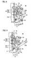
- FIG. 8 is a side view partly in cross section showing a modified example of a first strainer 30 in an ON state
- FIG. 9 is a side view partly in cross section showing the modified example of the first strainer 30 in an OFF state.
- the first strainer 30 of the modified example is characterized in that a stretching rod 45 is subjected to linear motion in a horizontal direction perpendicular to an axial line of the drum cylinder 2, whereby the snare assembly 8 moves in close contact with or apart from the bottom-side drumhead 3.
- a pair of arms 37A and 37B (where 37B is not shown) each have elongated holes 70, which are elongated in the horizontal direction perpendicular to the axial line of the drum cylinder 2, at the rear ends thereof, wherein both ends of the stretching rod 45 are inserted into the elongated holes 70 of the arms 37A and 37B so that the stretching rod 45 is supported to realize a free linear motion along the elongated holes 70.
- a pair of levers 40A and 40B are attached to the arms 37A and 37B and are supported to freely rotate about rotation axes 41A and 41B respectively.
- the 'switch' lever 40B has a knob 42 that is locked with a lock member 72 attached to the exterior circumferential surface of the drum cylinder 2 in the ON state in which the snare assembly 8 is stretched under tension and comes in close contact with the bottom-side drumhead 3, wherein the switch lever 40B is held substantially in parallel with the exterior circumferential surface of the drum cylinder 2.
- the lever 40B presses the stretching rod 45 to move in the right direction in FIG. 8 , thus pressing both ends of the stretching rod 45 to terminal ends of the elongated holes 70 opposite to the exterior circumferential surface of the drum cylinder 2 so as to stretch the snare assembly 13 under tension.
- the knob 42 of the switch lever 40B is released from the locked state with the lock member 72 and is rotated in the clockwise direction as shown in FIG. 9 , the lever 40A correspondingly rotates together with the switch lever 40B so as to release the stretching rod 45 from the pressed state.
- the stretching rod 45 is subjected to linear motion along the elongated holes 70 towards the exterior circumferential surface of the drum cylinder 2 due to the tension of the snare assembly 8, so that both ends of the stretching rod 45 are pressed to other ends of the elongated holes 70 close to the exterior circumferential surface of the drum cylinder 2, whereby the snare assembly 8 is loosened so as to move apart from the bottom-side drumhead 3; that is, the snare assembly 8 is switched over from the ON state to the OFF state. Therefore, both ends of the elongated holes 70 serve as stoppers for stopping the stretching rod 45 at ON/OFF positions respectively.
- the function of the switch lever 40B can be realized by modifying the stretching rod 45, wherein the stretching rod 45 is elongated so that the elongated portion thereof acts as a knob, by which the stretching rod 45 is directly moved in the horizontal direction.
- the terminal ends of the elongated holes 70 opposite to the exterior circumferential surface of the drum cylinder 2 can be modified in L-shapes, on which both ends of the stretching rod 45 are hooked so that the stretching rod 45 can be locked at the ON position. This eliminates the lock member 72 from the snare strainer.
- wires or strings arc used for the snare connection members 13, having flexibility, which are attached to both ends of the snare assembly 8.
- this invention is not necessarily limited to the present embodiment; hence, it is possible to use belts having appropriate widths, as shown in FIGS. 10 to 12 , for the snare connection members 13.
- the moving mechanism adapted to the stretching rod 45 is not necessarily limited to the aforementioned examples and can be modified in a variety of ways.
- the stretching rod 45 can be subjected to sliding motion along a prescribed slope.
Landscapes
- Physics & Mathematics (AREA)
- Engineering & Computer Science (AREA)
- Acoustics & Sound (AREA)
- Multimedia (AREA)
- Auxiliary Devices For Music (AREA)
- Surgical Instruments (AREA)
- Measuring And Recording Apparatus For Diagnosis (AREA)
- Tyre Moulding (AREA)
Description
- This invention relates to snare strainers that control snare assemblies (including snares) to move in close contact with or apart from drumheads.
- Snare drums produce special sound effects called tumbling effects, wherein snare assemblies each corresponding to a plurality of fine snares are controlled to move in close contact with or apart from bottom-side drumheads (corresponding to non-striking sides of snare drums), or they are controlled to move in close contact with or apart from both of bottom-side drumheads and top-side drumheads (corresponding to striking sides of snare drums), so that vibrations of drumheads are transmitted to snares to produce pattering or rattling sounds having light tone colors. The following documents teach adjustments of snares adapted to snare drums.
- (a) Japanese Examined Utility Model Publication No.
S58-50372 - (b)
U.S. Patent No. 6,008,445 . - (c)
U.S. Patent No. 5,844,157 . -
FIG. 10 is a perspective view showing the exterior appearance of a snare drum equipped with a snare assembly in relation to a bottom-side drumhead; andFIG. 11 is a perspective view showing the exterior appearance of the snare drum viewed from the top-side drumhead thereof.Reference numeral 1 designates a snare drum;reference numeral 2 designates a drum shell, i.e., a drum cylinder having openings at both ends;reference numeral 3 designates a bottom-side drumhead covering the bottom-side opening of thedrum cylinder 2;reference numeral 4 designates a top-side drumhead covering the top-side opening of thedrum cylinder 2;reference numerals 5 designate hoops (or clamp frames) engaging with the peripheries of the openings of thedrum cylinder 2;reference numerals 6 designate lugs;reference numerals 7 designate bolts for interconnecting thehoops 5 and thelugs 6 together;reference numeral 8 designates a snare assembly (i.e., snares) attached in relation to the bottom-side drumhead 3;reference numeral 9 designates a first strainer for holding amovable end 8A of thesnare assembly 8; and reference numeral 10 designates a second strainer for holding afixed end 8B of thesnare assembly 8. A snare strainer is constituted by thefirst strainer 9 and the second strainer 10. - The
snare assembly 8 includes a plurality offine snares 11 that are arranged in parallel with each other in the longitudinal direction with prescribed distances therebetween, a pair ofsnare mounting plates 12 that are respectively soldered to both ends of thesnares 11, and a pair of snare connection members having flexibility that are respectively attached to thesnare mounting plates 12. Thesnare connection members 13 constituted by belts are pressed bypressure plates first strainer 9 and the second strainer 10 respectively. Thesnare mounting plates 12 are arranged inside of thehoop 5 to come in close contact with the bottom-side drumhead 3 together with thesnares 11. Thissnare assembly 8 is referred to as an internal contact type snare assembly. In contrast, a full contact type snare assembly is designed such that the ends ofsnares 11 and thesnare mounting plates 12 are arranged outside of thehoop 5. - The
first strainer 9 controls themovable end 8A of thesnare assembly 8 to move in close contact with or apart from the bottom-side drumhead 3. Specifically, thefirst strainer 9 is constituted by afixed base 15 that is fixed to a prescribed position on the exterior circumferential surface of thedrum cylinder 2, a movingbase 16 that can be freely moved with respect to thefixed base 15 in vertical directions A and B, aswitch mechanism 17 that switches over the vertical movement of themoving base 16 with respect to thefixed base 15 so as to control themovable end 8A of thesnare assembly 8 to move in close contact with or apart from the bottom-side drumhead 3, and atension adjustment screw 18 that controls the vertical movement of the movingbase 16 with respect to thefixed base 15 so as to perform fine adjustment on the tension applied to thesnare assembly 8. Thesnare connection member 13 is tightly held between thepressure plate 14 and the movingbase 16, wherein thepressure plate 14 is fixed to the movingbase 16 by means of two square-headed bolts 19. - The
switch mechanism 17 includes anoperation lever 20 whose rotation is converted into a linear motion by means of a link or a cam (not shown) and is transmitted to the movingbase 16. Generally, two types of operations can be adapted to theoperation lever 20, wherein in the case ofFIG. 11 ,thc operation lever 20 is moved in circumferential directions C and D along the exterior circumferential surface of thedrum cylinder 2, and in the case ofFIG. 12 , theoperation lever 20 is moved in diameter directions E and F perpendicular to the exterior circumferential surface of thedrum cylinder 2. - In
FIG. 10 , the second strainer 10 is constituted by afixed base 23 that is fixed to a prescribed position on the exterior circumferential surface of thedrum cylinder 2, a moving base 24 that can be vertically moved with respect to thefixed base 23, and a tension adjustment screw 25 that controls the vertical movement of the moving base 24 so as to perform fine adjustment on the tension applied to thesnare assembly 8. Thesnare connection member 13 attached to the fixedend 8B of thesnare assembly 8 is tightly held between the moving base 24 and thepressure plate 26. - According to the snare strainer including the
first strainer 9 and the second strainer 10, when thesnare drum 1 is played without using thesnare assembly 8, theswitch mechanism 17 of thefirst strainer 9 is controlled to move themoving base 16 forward in the direction A, whereby the tension applied to thesnares 11 of thesnare assembly 8 is reduced so that both thesnares 11 and thesnare mounting plate 12 move apart from the bottom-side drumhead 3. When thesnare drum 1 is played by use of thesnare assembly 8, theswitch mechanism 17 is controlled to move themoving base 16 backward in the direction B, whereby thesnare connection member 13 is stretched so as to increase the tension of thesnares 11, so that both thesnares 11 and thesnare mounting plate 12 move in close contact with the bottom-side drumhead 3. In this 'contact' condition, when the top-side drumhead 4 is struck by a drumstick and the like, vibration occurring on the top-side drumhead 4 is transmitted to thesnares 11 via the bottom-side drumhead 3, whereby thesnares 11 correspondingly vibrate so as to produce unique sound of thesnare drum 1, i.e., pattering or rattling sound having a light tone color. - As described above, the
first strainer 9 is designed such that thesnare connection member 13 is fixed onto themoving base 16. In order to control thesnare assembly 8 to move in close contact with or apart from the bottom-side drumhead 3, thefirst strainer 9 requires a specific mechanism for moving the movingbase 16, wherein the rotary motion of theoperation lever 20 is converted into the linear motion by means of a link or a cam and is then transmitted to the movingbase 16. This requires an appropriate clearance allowing smooth sliding movement between thefixed base 15 and the movingbase 16, which in turn causes a problem in that when the movingbase 16 slides to move vertically during drum playing, the movingbase 16 may easily rattle and produce noise. - The aforementioned problem may be solved by minimizing the clearance so as to prevent the moving
base 16 from rattling. However, this requires strict dimensional tolerance and therefore increases the manufacturing cost. In addition, this may cause a relatively large friction when the movingbase 16 is slid to move vertically; hence, it becomes difficult to smoothly move the movingbase 16. - It is an object of the invention to provide a snare strainer having a simple structure with a reduced number of parts that do not require high precision in dimensions, wherein the snare strainer can be operated smoothly so as to avoid the occurrence of rattling and noise.
- The above object is achieved through a snare strainer according to
claim 1. - Further preferred aspects are provided in the dependent claims.
- These and other objects, aspects, and embodiments of the present invention will be described in more detail with reference to the following drawings, in which:
-
FIG. 1 is a front view showing a first strainer included in a snare strainer in accordance with a preferred embodiment of the invention, wherein the first strainer is placed in an ON state allowing a snare assembly to move in close contact with a bottom-side drumhead of a snare drum; -
FIG. 2 is a side view partly in cross section showing the first strainer in the ON state; -
FIG. 3 is an enlarged side view of the first strainer in the ON state, which is viewed from the right side inFIG. 1 ; -
FIG. 4 is an enlarged rear view of the first strainer in the ON state; -
FIG. 5 is an enlarged view showing essential parts of the first strainer in the ON state; -
FIG. 6 is a side view partly in cross section showing the first strainer in an OFF state allowing the snare assembly to move apart from the bottom-side drumhead of the snare drum; -
FIG. 7 is a side view partly in cross section showing a second strainer in the ON state allowing the snare assembly to move in close contact with the bottom-side drumhead of the snare drum; -
FIG. 8 is a side view partly in cross section showing a modified example of a first strainer in an ON state; -
FIG. 9 is a side view partly in cross section showing the modified example of the first strainer in an OFF state; -
FIG. 10 is a perspective view showing the exterior appearance of a conventionally known snare drum equipped with a snare strainer controlling a snare assembly to move in close contact with or apart from a bottom-side drumhead; -
FIG. 11 is a perspective view showing the snare drum viewed from a top-side drumhead; and -
FIG. 12 is a fragmentary perspective view showing another example the snare strainer attached to the snare drum. - This invention will be described in further detail by way of examples with reference to the accompanying drawings.
- A snare strainer according to a preferred embodiment of the invention will be described in detail with reference to
FIGS. 1 to 7 , wherein parts identical to those shown inFIGS. 10 to 12 are designated by the same reference numerals; hence, the detailed description thereof will be omitted as necessary. -
FIG. 1 is a front view showing a first strainer that is placed in an ON state allowing a snare assembly to move in close contact with a bottom-side drumhead of a snare drum;FIG. 2 is a side view partly in cross section showing the first strainer in the ON state;FIG. 3 is an enlarged side view of the first strainer in the ON state, which is viewed from the right side inFIG 1 ;FIG. 4 is an enlarged rear view of the first strainer in the ON state;FIG. 5 is an enlarged view showing essential parts of the first strainer in the ON state;FIG. 6 is a side view partly in cross section showing the first strainer in an OFF state allowing the snare assembly to move apart from the bottom-side drumhead of the snare drum; andFIG. 7 is a side view partly in cross section showing a second strainer in the ON state allowing the snare assembly to move in close contact with the bottom-side drumhead of the snare drum. - Specifically, in
FIGS. 1 to 7 , afirst strainer 30 and asecond strainer 31 are respectively attached to opposite positions on the exterior circumferential surface of adrum cylinder 2 of asnare drum 1, wherein they are assembled together to form a snare strainer that controls asnare assembly 8 to move in close contact with or apart from a bottom-side drumhead 3 of thesnare drum 1. - The
snare assembly 8 is constituted by a plurality offine snares 11 that are arranged in parallel with each other with prescribed distances therebetween, a pair ofsnare mounting plates 12 that are respectively soldered to both ends of thesnares 11, andsnare connection members 13 corresponding to wires or strings that are respectively attached to thesnare mounting plates 12. In the present embodiment, thesnare assembly 8 is of a full contact type in which both ends of thesnares 11 and thesnare mounting plates 12 are arranged outside of ahoop 5. Thesnare connection members 13 are held by holdingmembers first strainer 30 and thesecond strainer 31 respectively. - With reference to
FIGS. 1 to 6 , thefirst strainer 30 includes asnare stretching member 33 and afixed base 34, which fixes thesnare stretching member 33 to the exterior circumferential surface of thedrum cylinder 2. - The
snare stretching member 33 is constituted by theholding member 35 for holding thesnare connection member 13 attached to one end '8A' of thesnare assembly 8, an interconnection member 36 (seeFIG. 4 ) interconnected with thefixed base 34, and a pair ofarms interconnection member 36. - The
holding member 35 is constituted by a pair of afirst holding member 35A and asecond holding member 35B that are combined together to tightly hold the end portion of thesnare connection member 13 and are integrally connected together viascrews 38. - The
interconnection member 36 is formed in a block-like shape in which an internally threaded hole is formed at the center position to vertically penetrate thercthrough, whereby it is attached to thefixed base 34, and it can be vertically moved by means of aheight adjustment screw 62. - As shown in
FIG. 4 , thearms interconnection member 36 viascrews 39. A pair oflevers arms arms slopes 43, which are arranged opposite to the exterior circumferential surface of thedrum cylinder 2 and are respectively inclined by prescribed angles relative to the exterior circumferential surface of thedrum cylinder 2. - As shown in
FIG. 1 , the 'left-side'lever 40A has a shorter length compared with the 'right-side'lever 40B, wherein the front end thereof is supported by the rear end of thearm 37A to freely rotate about arotation axis 41A. The right-side lever 40B is sufficiently elongated in length compared with the left-side arm 40A, wherein the front end thereof is extended forwards in proximity to the fixedbase 34. Aknob 42 is fixed to the front end of thelever 40B so as to form a switch lever (designated by the reference numeral 40B), which switches over thesnare assembly 8 to move in close contact with or apart from the bottom-side drumhead 3. As shown inFIG. 3 , theswitch lever 40B is formed roughly in an L-shape in side view, the center of which matches arotation axis 41B. Herein, the rear end of theswitch lever 40B is inclined relative to the exterior circumferential surface of thedrum cylinder 2 and is elongated in a direction departing from the exterior circumferential surface of thedrum cylinder 2, wherein the center of the bent portion of theswitch lever 40B is supported by the rear end of thearm 37B in a free rotation manner about therotation axis 41B. Both the rotation axes 41 A and 41B match each other in line. - A stretching
rod 45 for supporting a portion between the holdingmember 35 and an outer peripheral end of the drumhead of thesnare connection member 13 is bridged between the rear ends of thelevers FIG. 5 , in the ON state allowing thesnare assembly 8 to come in close contact with the bottom-side drumhead 3, the stretchingrod 45 comes in close contact with the front ends of theslopes 43 of thearms snare assembly 13 is directed upwardly compared with the axial line of thelever 40A, so that theswitch lever 40B is maintained in the ON state. In the OFF state in which thesnare assembly 8 moves apart from the bottom-side drumhead 3, as shown inFIG. 6 , the stretchingrod 45 slightly descends down and moves closer to the exterior circumferential surface of thedrum cylinder 2, so that it comes in contact with the rear end of theslope 43. That is, the front ends and rear ends of theslopes 43 of thearms rod 45 at an ON position and an OFF position respectively. O-rings 46 (seeFIG. 1 ) are attached to both ends of the stretchingrod 45, which comes in contact with theslopes 43 of thearms switch lever 40B can be realized by partially modifying the stretchingrod 45 to be elongated outside of thearm 37B so that the elongated portion thereof serves as a switch knob. - As shown in
FIG. 4 , fixing portions that are outwardly bent and foldcd are respectively attached to the front ends of thearms bracket 50 that is roughly bent in an L-shape is fixed onto the fixingportions 48 viascrews 51. The holdingmember 35 is attached onto the upper surface of thebracket 50, wherein the holdingmember 35 and thebracket 50 are interconnected together by means of atension adjuster 52, which is used to adjust the tension applied to thesnare connection member 13 and is constituted by a screw having a knob. Thetension adjuster 52 is inserted into a leadingwall 50a, which is formed at the front end of thebracket 50, in a free rotation manner but is not allowed to be vertically moved, wherein it is engaged with an internally threaded hole formed at the center of the first holdingmember 35A. That is, when thetension adjuster 52 is rotated, the first holding member (in other words, the holding member 35) moves upwards or downwards along the surface of thebracket 50. This allows thesnare assembly 8 to be expanded or contracted in the length direction thereof while thesnare assembly 8 is fixedly set in close contact with the bottom-side drumhead 3. Thus, it is possible to adjust the tension applied to thesnares 11 of thesnare assembly 8. - As shown in
FIG. 2 , the fixedbase 34 is constituted by a fixingmember 60 that is formed by bending work using a metal plate and, a plurality ofscrews 61 for fixing the fixingmember 60 onto the circumferential wall of thedrum cylinder 2, and aheight adjuster 62 for interconnecting theinterconnection member 36 with the fixingmember 60, wherein the fixingmember 60 is formed in a rectangular shape in side view, both sides of which are opened. Theheight adjuster 62 adjusts the vertical height of the stretchingrod 45. Similar to thetension adjuster 52, theheight adjuster 62 is constituted by a screw having a knob. Theheight adjuster 62 is inserted into through holes, which are formed to penetrate through the upper and lower portions of the fixingmember 60, in a free rotation manner but is not allowed to be vertically moved, wherein it is engaged with an internally threaded hole formed in theinterconnection member 36. When theheight adjuster 62 is rotated, theinterconnection member 36 moves upwards or downwards along theheight adjuster 62. Thus, it is possible to adjust the height of the stretchingrod 45 measured from the level of the bottom-side drumhead 3 while thesnare assembly 8 is set in close contact with the bottom-side drumhead 3. - Similar to the
first strainer 30, as shown inFIG. 7 , thesecond strainer 31 includes asnare stretching member 70 and a fixedbase 71 for fixing thesnare stretching member 70 onto the exterior circumferential surface of thedrum cylinder 2. - The
snare stretching member 70 is constituted by a holdingmember 73 for holding thesnare connection member 13, which is attached to the other end (i.e., '8B') of thesnare assembly 8, aninterconnection member 74 interconnected with the fixedbase 71, and a pair ofarms 75 fixed to both ends of theinterconnection member 74. - The holding
member 73 is constituted by a pair of a first holdingmember 73A and asecond holding member 73B, which are integrally connected together viascrews 76 so as to tightly hold the end portion of thesnare connection member 13. - The
interconnection member 74 is formed in a block-like shape having an internally threaded hole, which is formed at the center thereof to vertically penetrate therethrough. Theinterconnection member 74 is attached to the fixedbase 71 in a vertically movable manner. Abracket 76 is fixed onto the upper surface of theinterconnection member 74. The holdingmember 73 is attached to thebracket 76 in a vertically movable manner, wherein the holdingmember 73 is interconnected with thebracket 76 by means of atension adjuster 77 for adjusting the tension applied to thesnare connection member 13. - The
tension adjuster 77 is constituted by a screw having a knob, wherein it is attached to aleading wall 76a, which is formed at the front end of thebracket 76, in a free rotation manner but is not allowed to be vertically moved. Thetension adjuster 77 is engaged with an internally threaded hole that is formed at the center of the first holdingmember 73A. When thetension adjuster 77 is rotated, the first holdingmember 73A (in other words, the holding member 73) moves upwards or downwards along the surface of thebracket 76. Thus, it is possible to adjust the tension of the snare assembly 8 (in other words, the tension applied to thesnares 11 of the snare assembly) while the snare assembly is set in close contact with the bottom-side drumhead 3. - A pair of
arms 75 each having a bent shape in side view are formed symmetrical to each other, wherein the front ends thereof are fixed to both sides of theinterconnection member 74 viascrews 80, and the rear ends thereof are elongated to depart from the exterior circumferential surface of thedrum cylinder 2 and are arranged to cross each other at a prescribed angle therebetween with respect to the exterior circumferential surface of thedrum cylinder 2. A stretchingrod 81 for supporting the intermediate portion of thesnare connection member 13 is bridged between the rear ends of thearms 75. - The fixed
base 71 is constituted by a fixingmember 90 that is formed by bending work using a metal plate and, a plurality ofscrews 91 for fixing the fixingmember 60 onto the circumferential wall of thedrum cylinder 2, and aheight adjuster 92 for interconnecting theinterconnection member 74 with the fixingmember 90, wherein the fixingmember 90 is formed in a rectangular shape in side view, both sides of which are opened. Theheight adjuster 92 adjusts the vertical height of the stretchingrod 81. Similar to thetension adjuster 77, theheight adjuster 92 is constituted by a screw having a knob. Theheight adjuster 92 is inserted into through holes, which are formed to penetrate through the upper and lower portions of the fixingmember 90, in a free rotation manner but is not allowed to be vertically moved, wherein it is engaged with an internally threaded hole formed in theinterconnection member 74. When theheight adjuster 92 is rotated, theinterconnection member 74 moves upwards or downwards along theheight adjuster 92. Thus, it is possible to adjust the height of the stretchingrod 81 measured from the level of the bottom-side drumhead 3 while thesnare assembly 8 is set in close contact with the bottom-side drumhead 3. - The
second strainer 31 is constituted basically similar to the aforementionedfirst strainer 30 except the following points: - (a) The
second strainer 31 does not have a lever for controlling thesnare assembly 8 to move in close contact with or apart from the bottom-side drumhead 3. - (b) Because of the aforementioned point, the 'second' stretching
rod 81 is bridged between the rear ends of thearms 75. - In order to play the
snare drum 1 having the snare strainer including thefirst strainer 30 and thesecond strainer 31 in the OFF state in which thesnare assembly 8 is not brought in close contact with the bottom-side drumhead 3, theswitch lever 40B of the first strainer 30 (which is originally maintained vertically as shown inFIG. 2 ) is rotated by a prescribed angle in a clockwise direction as shown inFIG. 6 and is thus inclined with respect to the exterior circumferential surface of thedrum cylinder 2. When theswitch lever 40B is rotated by a prescribed angle in the clockwise direction, the 'first' stretchingrod 45 of thefirst strainer 30 descends down to move close to the exterior circumferential surface of thedrum cylinder 2, thus releasing the tension of thesnare assembly 13, wherein it comes in contact with the rear ends of theslopes 43 of thearms snare assembly 8 is released from the stretched condition thereof, it naturally moves downwards due to its own weight and separates from the bottom-side drumhead 3. Thus, it is possible to switch over thesnare assembly 8 from the ON state to the OFF state in which thesnare drum 1 is played without using thesnare assembly 8. - In order to perform fine adjustment on the tension of the snare assembly 8 (i.e., the tension applied to the snares 11), it is necessary for a player to manually rotate the
tension adjusters first strainer 30 and thesecond strainer 31 respectively. That is, when the player rotates thetension adjuster member snare connection members 13 are correspondingly lifted up so that the tension applied to thesnares 11 increases. In contrast, when the player rotates thetension adjuster members snare assemblies 13 are correspondingly lowered in positions so that the tension applied to thesnares 11 decreases. - In order to perform fine adjustment on the degree of contact established between the
snare assembly 8 and the bottom-side drumhead 3, it is necessary for a player to manually rotate theheight adjusters arms height adjuster arms rod 45 bridged between thelevers arms height adjusters arms rod 45 is lowered in position so that the distance between thesnare assembly 8 and the bottom-side drumhead 3 increases; thus, it is possible to decrease the degree of contact with respect to thesnare assembly 8, whereby thesnares 11 are placed in 'weak' contact with the bottom-side drumhead 3. - According to the present embodiment, the
switch lever 40B is attached to thearm 37B in a free rotation manner, and the stretchingrod 45 bridged between thelevers snare connection member 13. Thus, it is possible to simplify the structure of the switch mechanism and to thereby reduce the total number of parts; and it is possible to avoid the occurrence of rattling and noise due to theswitch lever 40B. - In addition, the present embodiment can be commonly adapted to both the internal contact type of the snare assembly and the full contact type of the snare assembly.
- Furthermore, the present embodiment allows the stretching
rod 45 to rotate in the same direction in which theswitch lever 40B rotates, thus switching over the ON/OFF states with respect to thesnare assembly 8. This eliminates the necessity of arranging a moving direction converting mechanism in which the rotary motion is converted into the linear motion. The stretchingrod 45 can be smoothly moved without causing rattling and noise. - Next, a modified example of the present embodiment will be described with reference to
FIGS. 8 and 9 , wherein parts identical to those shown inFIGS. 1 to 6 are designated by the same reference numerals; hence, the detailed description thereof will be omitted. -
FIG. 8 is a side view partly in cross section showing a modified example of afirst strainer 30 in an ON state; andFIG. 9 is a side view partly in cross section showing the modified example of thefirst strainer 30 in an OFF state. - The
first strainer 30 of the modified example is characterized in that a stretchingrod 45 is subjected to linear motion in a horizontal direction perpendicular to an axial line of thedrum cylinder 2, whereby thesnare assembly 8 moves in close contact with or apart from the bottom-side drumhead 3. Herein, a pair ofarms holes 70, which are elongated in the horizontal direction perpendicular to the axial line of thedrum cylinder 2, at the rear ends thereof, wherein both ends of the stretchingrod 45 are inserted into theelongated holes 70 of thearms rod 45 is supported to realize a free linear motion along the elongated holes 70. A pair oflevers arms rotation axes Surfaces 71 of thelevers drum cylinder 2, have pressing surfaces for pressing the stretchingrod 45. The 'switch'lever 40B has aknob 42 that is locked with alock member 72 attached to the exterior circumferential surface of thedrum cylinder 2 in the ON state in which thesnare assembly 8 is stretched under tension and comes in close contact with the bottom-side drumhead 3, wherein theswitch lever 40B is held substantially in parallel with the exterior circumferential surface of thedrum cylinder 2. In the ON state, thelever 40B presses the stretchingrod 45 to move in the right direction inFIG. 8 , thus pressing both ends of the stretchingrod 45 to terminal ends of theelongated holes 70 opposite to the exterior circumferential surface of thedrum cylinder 2 so as to stretch thesnare assembly 13 under tension. When theknob 42 of theswitch lever 40B is released from the locked state with thelock member 72 and is rotated in the clockwise direction as shown inFIG. 9 , thelever 40A correspondingly rotates together with theswitch lever 40B so as to release the stretchingrod 45 from the pressed state. Thus, the stretchingrod 45 is subjected to linear motion along theelongated holes 70 towards the exterior circumferential surface of thedrum cylinder 2 due to the tension of thesnare assembly 8, so that both ends of the stretchingrod 45 are pressed to other ends of theelongated holes 70 close to the exterior circumferential surface of thedrum cylinder 2, whereby thesnare assembly 8 is loosened so as to move apart from the bottom-side drumhead 3; that is, thesnare assembly 8 is switched over from the ON state to the OFF state. Therefore, both ends of theelongated holes 70 serve as stoppers for stopping the stretchingrod 45 at ON/OFF positions respectively. - The function of the
switch lever 40B can be realized by modifying the stretchingrod 45, wherein the stretchingrod 45 is elongated so that the elongated portion thereof acts as a knob, by which the stretchingrod 45 is directly moved in the horizontal direction. In addition, the terminal ends of theelongated holes 70 opposite to the exterior circumferential surface of thedrum cylinder 2 can be modified in L-shapes, on which both ends of the stretchingrod 45 are hooked so that the stretchingrod 45 can be locked at the ON position. This eliminates thelock member 72 from the snare strainer. - In the present embodiment, wires or strings arc used for the
snare connection members 13, having flexibility, which are attached to both ends of thesnare assembly 8. Of course, this invention is not necessarily limited to the present embodiment; hence, it is possible to use belts having appropriate widths, as shown inFIGS. 10 to 12 , for thesnare connection members 13. - The moving mechanism adapted to the stretching
rod 45 is not necessarily limited to the aforementioned examples and can be modified in a variety of ways. For example, the stretchingrod 45 can be subjected to sliding motion along a prescribed slope. - The present embodiment is intended to be illustrative and not restrictive, since the scope of the invention is defined by the appended claims rather than by the description preceding them.
Claims (8)
- A snare strainer including a first strainer (30) and a second strainer (31), which are adopted to be attached to an exterior circumferential surface of a drum cylinder of a snare drum at opposite positions and adapted to control a snare assembly including snares to move in close contact with or apart from a drumhead of the snare drum, wherein said first strain (30) comprises a holding member (35) adapted to hold a snare connection member attached to a prescribed end of the snare assembly, characterised in that said first straider (30) also comprises a stretching rod (45) that is movably provided and adapted to support a portion between the holding member (35) and an outer peripheral end of the drumhead of the snare connection member, and wherein the stretching rod (45) is adapted to move to vary a distance from the holding member (35) to the outer peripheral end of the drumhead via the stretching rod (45), thus being adapted to control the snare assembly to move in close contact with or apart from the drumhead.
- A snare strainer according to claim 1, wherein the fust strainer (30) comprises a snare stretching member (33) including the stretching rod (45) and a fixed base (34) adapted to the snare stretching member (33) onto the exterior circumferential surface of the drum cylinder, and wherein the fixed base (34) includes a height adjuster (62) adapted to adjust a height of the stretching rod (45), said height being measurable in level based on the drumhead, by question of the snare stretching member (33).
- A snare strainer according to claim 1, wherein the holding member (35) includes a tension adjuster (52) adapted to adjust tension applied to the snare assembly.
- A snare strainer according to claim 2, wherein the holding membe (35) includes a tension adjuster (52) adapted to adjust tension applied to the snare assembly.
- A snare strainer according to claim 1, wherein the first strainer (30) includes a snare stretching member (33) and a fixed base (34) adapted to fix the snare stretching member (33) onto the exterior circumferential surface of the drum cylinder; the snare stretching member (33), includes the holding member (35), an interconnection member (36) adapted to establish interconnection with the fixed base (34), and a pair of arms (37A, 37B) that are elongated from both ends of the interconnection member (36); and a pair of levers (40A, 40B) between which the stretching rod (45) is bridged, arc respectively attached to the arms (37A, 37B) so as to freely rotate about rotation axes, whereby rotation of the levers (40A, 40B) is adapted to move, the snare assembly in close contact with or apart from the drumhead.
- A snare strainer according to claim 2, wherein the snare stretching member (33) includes the holding member (35), an interconnection member (36) adapted to establish interconnection with the fixed base (34), and a pair of arms (37A,37B) that are elongated from both ends of the interconnection member (36); and a pair of levers (40A,40B), between which the stretching rod (45) is bridged, are respectively attached to the arms (37A,37B) so as to freely rotate about rotation axes, whereby rotation of the levers (40A,40B) is adapted to move the snare assembly in close contact with or apart from the drumhead.
- A snare strainer according to claim 3, wherein the first strainer (30) includes a snare stretching member (33) and a fixed base (34) adapted to fix the snare stretching member (33) onto the exterior circumferential surface of the drum cylinder; the snare stretching member (33) includes the holding member (35), an interconnection member (36) adapted to establish interconnection with the fixed base (34), and a pair of arms (37A,37B) that are elongated from both ends of the interconnection member (36), and a pair of levers (40A,40B), between which the stretching rod (45) is bridged, arc respectively attached to the arms (37A,37B) so as to freely rotate about rotation axes, whereby rotation of the levers (40A,40B) is adapted to move the snare assembly in close contact with or apart from the drumhead.
- A snare strainer according to claim 4, wherein the snare stretching member (33) includes the holding member (35), an interconnection member (36) adapted to establish interconnection with the fixed base (34), and a pair of arms (37A,37B) that are elongated from both ends of the interconnection member (36); a pair of levers (410A,40B), between which the stretching rod (45) is bridged, arc respectively attached to the arms (37A,37B), so as to freely rotate about rotation axes, whereby rotation of the levers (40A,40B) is adapted to move the snare assembly in close contact with or apart from the drumhead.
Applications Claiming Priority (2)
| Application Number | Priority Date | Filing Date | Title |
|---|---|---|---|
| JP2004037957A JP3933136B2 (en) | 2004-02-16 | 2004-02-16 | Strainer device |
| JP2004037957 | 2004-02-16 |
Publications (3)
| Publication Number | Publication Date |
|---|---|
| EP1564718A2 EP1564718A2 (en) | 2005-08-17 |
| EP1564718A3 EP1564718A3 (en) | 2011-03-16 |
| EP1564718B1 true EP1564718B1 (en) | 2012-10-24 |
Family
ID=34697942
Family Applications (1)
| Application Number | Title | Priority Date | Filing Date |
|---|---|---|---|
| EP05003030A Not-in-force EP1564718B1 (en) | 2004-02-16 | 2005-02-14 | Snare strainer |
Country Status (5)
| Country | Link |
|---|---|
| US (1) | US7312389B2 (en) |
| EP (1) | EP1564718B1 (en) |
| JP (1) | JP3933136B2 (en) |
| CN (2) | CN1658280B (en) |
| ES (1) | ES2395933T3 (en) |
Cited By (1)
| Publication number | Priority date | Publication date | Assignee | Title |
|---|---|---|---|---|
| TWI693593B (en) * | 2019-04-03 | 2020-05-11 | 功學社教育用品股份有限公司 | Strainer assembly for snare drum |
Families Citing this family (18)
| Publication number | Priority date | Publication date | Assignee | Title |
|---|---|---|---|---|
| JP3933136B2 (en) * | 2004-02-16 | 2007-06-20 | ヤマハ株式会社 | Strainer device |
| US7745712B2 (en) * | 2005-03-18 | 2010-06-29 | Ronn Dunnett | Quick release for snare strainer and butt end apparatus and method |
| US7220905B2 (en) * | 2005-03-25 | 2007-05-22 | Pearl Musical Instrument Co. | Strainer for a snare drum |
| DE202007000375U1 (en) * | 2007-01-14 | 2007-09-20 | Lutz, Bernard Martin | Device for adjusting and locking a snare band |
| US7977558B2 (en) * | 2007-11-30 | 2011-07-12 | Sakae Rhythm Musical Instrument Ltd. | Strainer, and snappy holding structure by the strainer |
| JP4977161B2 (en) * | 2009-03-26 | 2012-07-18 | 星野楽器株式会社 | Strainer device and snare drum |
| US7728211B1 (en) * | 2009-05-15 | 2010-06-01 | D'addario & Company, Inc. | Snare drum end plate and strap |
| US8143507B2 (en) * | 2009-11-20 | 2012-03-27 | Drum Workshop, Inc. | Adjusting device for snare drum |
| US8618396B1 (en) | 2011-05-17 | 2013-12-31 | Ronn Dunnett | Modular concert drum throw |
| CN102568446B (en) * | 2012-02-14 | 2014-01-08 | 张树岩 | String pulling device |
| US8791348B2 (en) * | 2012-12-23 | 2014-07-29 | Chosen Fat Co., Ltd. | Adjustment assembly for snare wires |
| CN104637473A (en) * | 2013-11-06 | 2015-05-20 | 天津市津宝乐器有限公司 | Snare drum |
| US9082376B1 (en) * | 2014-01-23 | 2015-07-14 | Pearl Music Instrument Co. | Snare drum strainer with locking assembly |
| US9697810B2 (en) * | 2014-11-13 | 2017-07-04 | Pearl Musical Instrument Co. | Strainer for a snare drum |
| JP6515863B2 (en) * | 2016-04-21 | 2019-05-22 | ヤマハ株式会社 | Musical instrument |
| DE112018000413T5 (en) * | 2017-01-17 | 2019-10-10 | Drum Workshop, Inc. | Drum with adjustable auxiliary device |
| US10984767B2 (en) | 2017-01-17 | 2021-04-20 | Drum Workshop, Inc. | Drum with self-aligning snare |
| US11646004B2 (en) * | 2020-03-16 | 2023-05-09 | John Spinelli | Snare drum throw off |
Family Cites Families (11)
| Publication number | Priority date | Publication date | Assignee | Title |
|---|---|---|---|---|
| JPS584141A (en) | 1981-07-01 | 1983-01-11 | Muromachi Kagaku Kogyo Kk | Photosensitive laminate and using method for it |
| JPS5850372U (en) | 1981-09-30 | 1983-04-05 | 株式会社山武 | Bearing structure of reed screw in electric valve operating device |
| JPS60163500A (en) | 1984-02-03 | 1985-08-26 | 株式会社東芝 | Methof of picking up small piece seal |
| JPH0493889A (en) | 1990-08-03 | 1992-03-26 | Canon Inc | Pattern processing method |
| JP2675740B2 (en) | 1993-07-19 | 1997-11-12 | 富士電気化学株式会社 | Method of manufacturing rotor for stepping motor |
| US5557053A (en) * | 1995-04-19 | 1996-09-17 | Nickel; Gregory L. | Snare strainer for a drum |
| US5844157A (en) | 1996-01-18 | 1998-12-01 | Kasha; Robert J. | Multiple adjusting snare assembly |
| TW345297U (en) * | 1998-02-13 | 1998-11-11 | Tay E Co Ltd | Adjusting secure seat for sound-wire of drum |
| US6008445A (en) | 1998-06-18 | 1999-12-28 | Chen; Chang-Hui | Adjustment for drum snare |
| JP3583072B2 (en) | 2000-12-28 | 2004-10-27 | 星野楽器株式会社 | Snare drum snare strainer |
| JP3933136B2 (en) * | 2004-02-16 | 2007-06-20 | ヤマハ株式会社 | Strainer device |
-
2004
- 2004-02-16 JP JP2004037957A patent/JP3933136B2/en not_active Expired - Lifetime
-
2005
- 2005-02-11 US US11/056,513 patent/US7312389B2/en active Active
- 2005-02-14 EP EP05003030A patent/EP1564718B1/en not_active Not-in-force
- 2005-02-14 ES ES05003030T patent/ES2395933T3/en active Active
- 2005-02-16 CN CN2005100079921A patent/CN1658280B/en not_active Expired - Fee Related
- 2005-02-16 CN CNU2005200041135U patent/CN2826598Y/en not_active Expired - Fee Related
Cited By (1)
| Publication number | Priority date | Publication date | Assignee | Title |
|---|---|---|---|---|
| TWI693593B (en) * | 2019-04-03 | 2020-05-11 | 功學社教育用品股份有限公司 | Strainer assembly for snare drum |
Also Published As
| Publication number | Publication date |
|---|---|
| CN1658280B (en) | 2010-05-12 |
| ES2395933T3 (en) | 2013-02-18 |
| JP2005227660A (en) | 2005-08-25 |
| EP1564718A2 (en) | 2005-08-17 |
| JP3933136B2 (en) | 2007-06-20 |
| CN1658280A (en) | 2005-08-24 |
| US7312389B2 (en) | 2007-12-25 |
| US20050188818A1 (en) | 2005-09-01 |
| EP1564718A3 (en) | 2011-03-16 |
| CN2826598Y (en) | 2006-10-11 |
Similar Documents
| Publication | Publication Date | Title |
|---|---|---|
| EP1564718B1 (en) | Snare strainer | |
| US7741550B2 (en) | Strainer system of snare drum and snare drum with the strainer system | |
| JP3583072B2 (en) | Snare drum snare strainer | |
| CA2174381C (en) | A snare strainer for a drum | |
| US8927842B1 (en) | Drum system | |
| US5301592A (en) | Bass drum foot pedal | |
| US20100242707A1 (en) | Strainer and snare drum | |
| US7223910B2 (en) | Snare drum | |
| US6977333B2 (en) | Remote hi-hat apparatus operated by the foot pedal of the first hi-hat apparatus | |
| US7262355B2 (en) | Snare strainer | |
| US8426711B2 (en) | Snare strainer | |
| JP4495042B2 (en) | stand | |
| KR100590127B1 (en) | Keyboard Instrument Having Pedal Mechanism | |
| US6700046B2 (en) | Snare-switch mechanism connected to the snareband of a snare drum | |
| US20100005948A1 (en) | Hi-hat universal foot pedal lock | |
| US20110041670A1 (en) | Vertically aligned drum set | |
| US7135633B2 (en) | Pedal locking device and pedal device | |
| US5659144A (en) | Foot pedal for a drum | |
| JPS58132278A (en) | Harp with voice pitch adjusting mechanism | |
| CN111862902A (en) | Sound wire combination for sound wire small drum | |
| KR100433864B1 (en) | Tension strength adjustion equipment of guitar string | |
| US6632988B1 (en) | Damper adjustment device | |
| JP4085036B2 (en) | Piano key load variable device | |
| GB2256521A (en) | Drum with multiple snares | |
| US20040011185A1 (en) | Snare gate for drum |
Legal Events
| Date | Code | Title | Description |
|---|---|---|---|
| PUAI | Public reference made under article 153(3) epc to a published international application that has entered the european phase |
Free format text: ORIGINAL CODE: 0009012 |
|
| AK | Designated contracting states |
Kind code of ref document: A2 Designated state(s): AT BE BG CH CY CZ DE DK EE ES FI FR GB GR HU IE IS IT LI LT LU MC NL PL PT RO SE SI SK TR |
|
| AX | Request for extension of the european patent |
Extension state: AL BA HR LV MK YU |
|
| RAP1 | Party data changed (applicant data changed or rights of an application transferred) |
Owner name: YAMAHA CORPORATION |
|
| PUAL | Search report despatched |
Free format text: ORIGINAL CODE: 0009013 |
|
| AK | Designated contracting states |
Kind code of ref document: A3 Designated state(s): AT BE BG CH CY CZ DE DK EE ES FI FR GB GR HU IE IS IT LI LT LU MC NL PL PT RO SE SI SK TR |
|
| AX | Request for extension of the european patent |
Extension state: AL BA HR LV MK YU |
|
| 17P | Request for examination filed |
Effective date: 20110418 |
|
| AKX | Designation fees paid |
Designated state(s): DE ES GB NL |
|
| GRAP | Despatch of communication of intention to grant a patent |
Free format text: ORIGINAL CODE: EPIDOSNIGR1 |
|
| GRAS | Grant fee paid |
Free format text: ORIGINAL CODE: EPIDOSNIGR3 |
|
| GRAA | (expected) grant |
Free format text: ORIGINAL CODE: 0009210 |
|
| AK | Designated contracting states |
Kind code of ref document: B1 Designated state(s): DE ES GB NL |
|
| REG | Reference to a national code |
Ref country code: GB Ref legal event code: FG4D |
|
| REG | Reference to a national code |
Ref country code: NL Ref legal event code: T3 |
|
| REG | Reference to a national code |
Ref country code: DE Ref legal event code: R096 Ref document number: 602005036633 Country of ref document: DE Effective date: 20121220 |
|
| REG | Reference to a national code |
Ref country code: ES Ref legal event code: FG2A Ref document number: 2395933 Country of ref document: ES Kind code of ref document: T3 Effective date: 20130218 |
|
| PLBE | No opposition filed within time limit |
Free format text: ORIGINAL CODE: 0009261 |
|
| STAA | Information on the status of an ep patent application or granted ep patent |
Free format text: STATUS: NO OPPOSITION FILED WITHIN TIME LIMIT |
|
| 26N | No opposition filed |
Effective date: 20130725 |
|
| REG | Reference to a national code |
Ref country code: DE Ref legal event code: R097 Ref document number: 602005036633 Country of ref document: DE Effective date: 20130725 |
|
| PGFP | Annual fee paid to national office [announced via postgrant information from national office to epo] |
Ref country code: NL Payment date: 20190218 Year of fee payment: 15 |
|
| PGFP | Annual fee paid to national office [announced via postgrant information from national office to epo] |
Ref country code: DE Payment date: 20190219 Year of fee payment: 15 Ref country code: ES Payment date: 20190320 Year of fee payment: 15 Ref country code: GB Payment date: 20190218 Year of fee payment: 15 |
|
| REG | Reference to a national code |
Ref country code: DE Ref legal event code: R119 Ref document number: 602005036633 Country of ref document: DE |
|
| REG | Reference to a national code |
Ref country code: NL Ref legal event code: MM Effective date: 20200301 |
|
| GBPC | Gb: european patent ceased through non-payment of renewal fee |
Effective date: 20200214 |
|
| PG25 | Lapsed in a contracting state [announced via postgrant information from national office to epo] |
Ref country code: NL Free format text: LAPSE BECAUSE OF NON-PAYMENT OF DUE FEES Effective date: 20200301 |
|
| PG25 | Lapsed in a contracting state [announced via postgrant information from national office to epo] |
Ref country code: GB Free format text: LAPSE BECAUSE OF NON-PAYMENT OF DUE FEES Effective date: 20200214 Ref country code: DE Free format text: LAPSE BECAUSE OF NON-PAYMENT OF DUE FEES Effective date: 20200901 |
|
| REG | Reference to a national code |
Ref country code: ES Ref legal event code: FD2A Effective date: 20210705 |
|
| PG25 | Lapsed in a contracting state [announced via postgrant information from national office to epo] |
Ref country code: ES Free format text: LAPSE BECAUSE OF NON-PAYMENT OF DUE FEES Effective date: 20200215 |