EP1564548A1 - Microwave resonator excited in higher modes for measuring dielectric properties of a product - Google Patents
Microwave resonator excited in higher modes for measuring dielectric properties of a product Download PDFInfo
- Publication number
- EP1564548A1 EP1564548A1 EP04003110A EP04003110A EP1564548A1 EP 1564548 A1 EP1564548 A1 EP 1564548A1 EP 04003110 A EP04003110 A EP 04003110A EP 04003110 A EP04003110 A EP 04003110A EP 1564548 A1 EP1564548 A1 EP 1564548A1
- Authority
- EP
- European Patent Office
- Prior art keywords
- resonator
- product
- sensor according
- microwave sensor
- electric field
- Prior art date
- Legal status (The legal status is an assumption and is not a legal conclusion. Google has not performed a legal analysis and makes no representation as to the accuracy of the status listed.)
- Withdrawn
Links
Images


Classifications
-
- D—TEXTILES; PAPER
- D01—NATURAL OR MAN-MADE THREADS OR FIBRES; SPINNING
- D01G—PRELIMINARY TREATMENT OF FIBRES, e.g. FOR SPINNING
- D01G31/00—Warning or safety devices, e.g. automatic fault detectors, stop motions
- D01G31/006—On-line measurement and recording of process and product parameters
-
- G—PHYSICS
- G01—MEASURING; TESTING
- G01N—INVESTIGATING OR ANALYSING MATERIALS BY DETERMINING THEIR CHEMICAL OR PHYSICAL PROPERTIES
- G01N22/00—Investigating or analysing materials by the use of microwaves or radio waves, i.e. electromagnetic waves with a wavelength of one millimetre or more
-
- G—PHYSICS
- G01—MEASURING; TESTING
- G01N—INVESTIGATING OR ANALYSING MATERIALS BY DETERMINING THEIR CHEMICAL OR PHYSICAL PROPERTIES
- G01N22/00—Investigating or analysing materials by the use of microwaves or radio waves, i.e. electromagnetic waves with a wavelength of one millimetre or more
- G01N22/04—Investigating moisture content
-
- G—PHYSICS
- G01—MEASURING; TESTING
- G01N—INVESTIGATING OR ANALYSING MATERIALS BY DETERMINING THEIR CHEMICAL OR PHYSICAL PROPERTIES
- G01N33/00—Investigating or analysing materials by specific methods not covered by groups G01N1/00 - G01N31/00
- G01N33/36—Textiles
- G01N33/362—Textiles material before processing, e.g. bulk cotton or wool
Definitions
- the invention relates to a microwave sensor for measuring a dielectric property, in particular the density and / or humidity of a product, with a microwave resonator, wherein a product introduced into the resonator with a in the Resonator generated resonant microwave field to determine appropriate measures interacts.
- the field energy is in a certain area of the resonator concentrated.
- the mass load of the resonator in the field of high field energy is limited because too high a mass load to a distortion of the measured signal due of losses.
- the use of several resonators only for one Part of the product is laborious and can lead to systematic errors due to differences the resonators or the corresponding control and evaluation to lead.
- With extended, in particular web-shaped products there is another Problem is, the product over a larger extent, for example, over the entire Width of a product web to capture.
- the enlargement of the high field energy range, for example, by increasing the wavelength would be to designs with not practical dimensions.
- the use of several smaller resonators The expansion of the product is also for the reasons mentioned above disadvantageous.
- EP 0 889 321 A is a microwave sensor for measuring on an elongated Sample with a flat, filled with dielectric resonator and a through the Resonator extending through hole for the sample known.
- an approximately homogeneous microwave field relatively low intensity.
- From DE 102 04 328 A is a microwave sensor for determining the mass of a Sliver in a spinning preparation machine is known, having a resonator with has two sample volumes for two fiber composites.
- WO 00/55606 A is microwave sensor with a resonant strip conductor to Measurement of the mass of a fibrous material known.
- the stripline forms a half-wave of the electric field with intensity maxima at both ends, on each of which a passage is provided for a product stream.
- the strong Inhomogeneous fields of the open line ends are disadvantageous in terms of measurement technology.
- Farther is a shield of the stripline in the form of a metallic housing required to prevent a falsification of the measurement by radiation losses. The housing must be carefully tuned to resonances near the measurement frequency to avoid. The structure of the sensor is therefore relatively expensive.
- the object of the invention is an inexpensive microwave sensor with to provide improved measurement accuracy, and preferably accurate measurement a relatively large amount of product and / or an extended product to allow.
- the invention solves this problem in particular by the fact that in the resonator in a Direction at least two half-waves of the electric field are formed, wherein the product delivery in at least a range of high field intensity of one of the half-waves of the electric field.
- the invention enables the reduction of the mass load of the resonator with respect to the total energy stored in the resonator, which makes it possible to improve the measuring accuracy and at high mass load may even prevent a collapse of the electric field can.
- the sample feed is in a region of high field energy arranged at least one half-wave around a corresponding intensity maximum, to achieve a high measuring sensitivity.
- the invention is delimited from a high-mode resonator as described in EP 0 889 321 A, where the sample feed into a central resonator region with very low field intensity occurs.
- a product feed takes place in at least two in each case a half-wave the resonator sections corresponding to the electric field.
- This allows the distribution of the product over several half waves of the electric field.
- This will reduces the mass load per half-wave or per resonator section.
- the mass load per resonator section be reduced to an appropriate level.
- a relatively large extension of a product in one direction can be detected by dividing it into several half-waves where the extent of a single high field strength region is relatively low can be.
- the areas of high field strength are within a Resonator generated; the use of several smaller resonators is not required.
- half-waves of the electric field in the case of a certain Measuring frequency a belly of the cos-shaped field, i. starting from a zero of the field over a field maximum or minimum to the next zero.
- a Half wave has a half wavelength corresponding extension.
- the usage at least two half-wavelengths means that the cavity resonator in a higher mode is operated.
- half-wave refers to a field area that is based on a field Zero of the field over a field maximum or minimum to the next zero runs. Alternatively, the term may refer to the highest intensity measurement frequency Respectively.
- the product is in at least two maxima of the electric field accordingly arranged at least two half-waves. If for all parts of the product an equally weighted average of the measurand is to be obtained are the Product parts in each resonator section expediently substantially in the respective maximum of the electric field arranged. Through targeted deviation the arrangement of individual product parts of the maximum in the respective resonator sections can set any desired weighting of the individual product parts become.
- the resonator can have different designs. Preferably it is is a shielded resonator or cavity, i. one of metallic Walls limited cavity, except for openings for sample delivery is essentially closed. In a cavity resonator is internally a Cavity resonance excited. This construction is particularly inexpensive, for example in comparison to the stripline of WO 00/55606 A. Particularly simple and therefore preferred is a rectangular resonator. It can also be a particular about Chokes open resonator act. However, the invention relates only to such resonators, in which the product is introduced for measurement in the Resonatorraum or by this is passed. The subject-matter of the application is therefore delimited Such (stray field) resonators, in which the measurement by means of an external electrical Streufeldes done, so that there is a completely different field profile.
- the invention for measurement at one through the resonator guided continuous product flow, since here the product mass or the product expansion is predetermined and can not be tuned to the resonator.
- the at least two resonator sections expediently for carrying out in each case at least one product strand set up. It may be advantageous if passing through each resonator section two or even more strands of product are passed, as when tearing a strand of fibers this is carried by the other strand. However, preferably no more than two strands of product passed through each resonator section to the corresponding one To keep the mass load as low as possible.
- Number and arrangement of the resonator sections can be freely adapted to the respective requirements be adjusted. It can be a one-dimensional, in particular linear Arrangement example, across the width of a product web act. Also one annular arrangement is included, wherein the at least two half-waves in the circumferential direction are arranged. It can also be a two-dimensional arrangement act in which in two directions in each case at least two half-waves of the electric Field are provided in the resonator. Even a three-dimensional arrangement is possible.
- the number of resonator sections is preferably at least three, preferably at least four. It is possible to empty unneeded resonator sections to run.
- a four-strand product with a resonator with four resonator sections are measured by passing two strands through two Resonator sections are guided and the two remaining resonator sections empty to run. It can therefore the same resonator design (for example, resonator with four Resonatorabitesen) for different applications (in the example mentioned a up to eight strands) can be used.
- not all resonator sections must have a sample feed.
- the resonator if necessary the cavity resonator, can with a solid dielectric having a dielectric constant greater than one, preferably at least two, farther preferably at least five be filled.
- Usual materials, especially ceramics, are known in the art.
- the use of a dielectric filling allowed the storage of field energy in a comparatively smaller space and allows therefore smaller designs.
- “Essentially” means apart from means for coupling the microwaves, for Performing the sample and the like.
- the resonator can also essentially be filled with air, which is a particularly simple and inexpensive construction represents.
- a microwave sensor 10 has a cavity 11 in which a standing Microwave field is generated.
- the coupling and decoupling of the microwave field takes place by means of coupling devices 12.
- Microwaves are by means of one of a Computer 13 controlled generator 14 generates and by means of a line to the coupling device 12a headed.
- Via the coupling device 12b is a microwave signal decoupled from the resonator 11 and by means of a line an analyzer 15th supplied, the output signal from the computer 13 can be processed.
- generator 14, analyzer 15 and computer 13 are expediently in a measuring unit 16 summarized.
- the resonator 11 has a plurality of resonator sections 17a, 17b, 17c,.
- the separation into different resonator sections is shown in dashed lines in the figures Lines indicated.
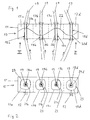
- Figures 1, 2, 5, 6, 7, 9 respectively relate to elongate rectangular cavity resonators with, for example, four or two resonator sections.
- Elongated means that the expansion along a longitudinal axis by at least a factor 2, preferably at least a factor of 3, more preferably at least one Factor 5 is longer than the extent along the two perpendicular to the longitudinal axis Directions.
- the resonator sections 17 are in series along the longitudinal axis of the resonator 11 arranged. FIG.
- FIG. 3 shows a resonator in which the resonator sections in FIG Columns and rows, i. are arranged in the form of a matrix.
- the number of columns, Rows and, more generally, the arrangement of the resonator sections may be arbitrary be adapted to the respective requirements.
- Fig. 4 relates to an annular resonator 11, in which the resonator sections 17 in series along the ring axis of the resonator 11 are arranged.
- four resonator sections 17b, 17d, 17f, 17h empty. In general, any number of resonator sections 17 empty.
- each resonator section has openings 21a, 21b, 21c,. on, which may be provided in particular in the resonator bounding walls.
- each separate openings 21 for the entry and exit of the Sample 19 is provided in and out of the resonator 11.
- the Size of the openings 21 approximately the cross section of the product to be measured 19.
- the shape of the openings 21 is adapted to the product cross section.
- the openings 21 are preferably circular.
- the resonator is up to the product feed openings 21 substantially closed. Closed means for the used microwaves impermeable. The above features help to reduce the adverse Radiation of microwave energy from the resonator at.
- Probenfiihrungs Rheinen 18a, 18b, 18c, ... for example Tubes 20a, 20b, 20c, ..., preferably made of low-loss dielectric can exist with low temperature dependence, such as quartz glass.
- the microwave frequency generated by the generator 14 is tuned so that in the resonator 11 with a standing wave with at least two bulbous half-waves each forms a local intensity maximum.
- Figs. 1, 5, 9 are exemplary electric field lines 22 in the case of a microwave with a certain frequency located. In this case, a cos-shaped propagates per resonator section 17 Half-wave of the electric field. Any other field distributions with at least two half waves, even with more than one frequency, generally with any Frequency distribution, and / or multiple maxima per resonator section are also possible.
- lines 23 of constant field intensity are shown. Within the lines 23 there is a region of high field intensity with a local one Intensity maximum, which is approximately in the center of the respective resonator 17. However, this is generally not mandatory. Outside the lines 23 is the field intensity is lower than inside.
- the mass load per resonator section 17 is correspondingly reduced, in the example of FIG. 1, for example by a factor of 4, in the example of FIG. 3, for example by a factor of 9.
- the individual parts of the sample 19 are each by a closely arranged around the respective intensity maximum range of the respective resonator section 17 led. As can be seen for example in FIG. 1, this is in this area the field strength is about constant. Position and orientation changes of the sample as well as spatial inhomogeneities within the product stream therefore do not affect or at most little on the measurement signal, since all parts of the product stream with the same weighting - due to the approximately constant field strength - in the measurement signal as can be seen in the examples of Figs. 1 to 4, 7, 9.
- An opening 21 can be arranged diverging from the respective intensity maximum to individual Allow weighting of individual product parts.
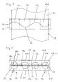
- the embodiment according to FIG. 5, 6 relates to the measurement on a flat product 31, in particular a plate or web-shaped product, for example paper.
- the Opening 21 is slot-shaped, wherein slot 30 consists of slot sections 21a, 21b, 21c, 21d is composed.
- the length of the slot 30 is the width of the paper web 31 adapted.
- Measuring unit 16 are used at the same microwave frequency by simply a linear arrangement of eight instead of four resonator sections 17 is selected, whereby the length of the resonator 11 would approximately double. In this way must the size of the resonator 11 only along the longitudinal axis, i. just one dimension, be changed while the size of the resonator 11 otherwise unchanged can stay.
- the resonator 11 may consist of two separate resonator halves, between which a sample feed slot is formed.
- the microwave coupling devices 12 each arranged in different resonator halves. It is also possible to use stranded products with a slotted resonator measure up.
- FIG. 7 illustrates that the walls of the resonator 11th not completely closed, but only substantially impermeable to microwaves should be.
- separators 32, 33 for example Dividing plates are provided, which are preferably periodically at a distance from each other are arranged, which is less than that corresponding to the propagation cutoff frequency Wavelength of the microwave field.
- the field can between the dividing plates 32 something but in total is substantially in the interior of the resonator 11 concentrated.
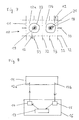
- the embodiment shown in FIG. 9 relates to a resonator 11 for measurement a portioned product 19.
- the individual portions may be in a sample container 33, for example, a quartz glass tube, are.
- the resonator 11 has only one opening 21 in the resonator walls per resonator section 17a, 17b for introducing the product 19. This can be automated, for example by means of a Robot made. Guide means 20 are preferred, but not necessarily provided. Also in this example, at relatively low mass load per resonator section 17 measured with only one resonator 11 a relatively large sample mass become.
Abstract
Description
Die Erfindung betrifft einen Mikrowellensensor zur Messung einer dielektrischen Eigenschaft, insbesondere der Dichte und/oder Feuchte eines Produkts, mit einem Mikrowellenresonator, wobei ein in den Resonator eingeführtes Produkt mit einem in dem Resonator erzeugten resonanten Mikrowellenfeld zur Ermittlung geeigneter Meßgrößen in Wechselwirkung steht.The invention relates to a microwave sensor for measuring a dielectric property, in particular the density and / or humidity of a product, with a microwave resonator, wherein a product introduced into the resonator with a in the Resonator generated resonant microwave field to determine appropriate measures interacts.
Bei derartigen Sensoren ist die Feldenergie in einem bestimmten Bereich des Resonators konzentriert. Die Massebelastung des Resonators im Bereich hoher Feldenergie ist begrenzt, da eine zu hohe Massebelastung zu einer Verfälschung des Meßsignals aufgrund von Verlusten führt. Die Verwendung mehrerer Resonatoren jeweils nur für einen Teil des Produkts ist aufwendig und kann zu systematischen Fehlern aufgrund von Unterschieden der Resonatoren bzw. der entsprechenden Steuer- und Auswerteelektronik führen. Bei ausgedehnten, insbesondere bahnförmigen Produkten besteht ein weiteres Problem darin, das Produkt über eine größere Ausdehnung, beispielsweise über die gesamte Breite einer Produktbahn zu erfassen. Die Vergrößerung des Bereichs hoher Feldenergie, beispielsweise durch Vergrößerung der Wellenlänge, würde zu Bauformen mit nicht praktikablen Abmessungen führen. Die Verwendung mehrerer kleinerer Resonatoren über die Ausdehnung des Produkts ist aus den oben genannten Gründen ebenfalls nachteilig.In such sensors, the field energy is in a certain area of the resonator concentrated. The mass load of the resonator in the field of high field energy is limited because too high a mass load to a distortion of the measured signal due of losses. The use of several resonators only for one Part of the product is laborious and can lead to systematic errors due to differences the resonators or the corresponding control and evaluation to lead. With extended, in particular web-shaped products, there is another Problem is, the product over a larger extent, for example, over the entire Width of a product web to capture. The enlargement of the high field energy range, for example, by increasing the wavelength would be to designs with not practical dimensions. The use of several smaller resonators The expansion of the product is also for the reasons mentioned above disadvantageous.
Aus der EP 0 889 321 A ist ein Mikrowellensensor zur Messung an einer länglichen Probe mit einem flachen, mit Dielektrikum gefüllten Resonator und einer durch den Resonator verlaufenden Durchgangsbohrung für die Probe bekannt. In dem zentral im Resonator angeordneten Meßbereich existiert ein näherungsweise homogenes Mikrowellenfeld relativ geringer Intensität. From EP 0 889 321 A is a microwave sensor for measuring on an elongated Sample with a flat, filled with dielectric resonator and a through the Resonator extending through hole for the sample known. In the central in Resonator arranged measuring range exists an approximately homogeneous microwave field relatively low intensity.
Aus der DE 102 04 328 A ist ein Mikrowellensensor zur Bestimmung der Masse eines Faserbandes in einer Spinnereivorbereitungsmaschine bekannt, der einen Resonator mit zwei Probenvolumina für zwei Faserverbände aufweist.From DE 102 04 328 A is a microwave sensor for determining the mass of a Sliver in a spinning preparation machine is known, having a resonator with has two sample volumes for two fiber composites.
Aus der WO 00/55606 A ist Mikrowellensensor mit einem resonanten Streifenleiter zur Messung der Masse eines faserigen Materials bekannt. Entlang dem Streifenleiter bildet sich eine Halbwelle des elektrischen Feldes mit Intensitätsmaxima an beiden Enden aus, an denen jeweils eine Durchführung für einen Produktstrom vorgesehen ist. Die stark inhomogenen Felder der offenen Leitungsenden sind meßtechnisch nachteilig. Weiterhin ist eine Abschirmung des Streifenleiters in Form eines metallischen Gehäuses erforderlich, um eine Verfälschung der Messung durch Strahlungsverluste zu verhindern. Das Gehäuse muß sorgfältig abgestimmt sein, um Resonanzen in der Nähe der Meßfrequenz zu vermeiden. Der Aufbau des Sensors ist daher vergleichsweise aufwendig.From WO 00/55606 A is microwave sensor with a resonant strip conductor to Measurement of the mass of a fibrous material known. Along the stripline forms a half-wave of the electric field with intensity maxima at both ends, on each of which a passage is provided for a product stream. The strong Inhomogeneous fields of the open line ends are disadvantageous in terms of measurement technology. Farther is a shield of the stripline in the form of a metallic housing required to prevent a falsification of the measurement by radiation losses. The housing must be carefully tuned to resonances near the measurement frequency to avoid. The structure of the sensor is therefore relatively expensive.
Die Aufgabe der Erfindung besteht darin, einen unaufwendigen Mikrowellensensor mit verbesserter Meßgenauigkeit bereitzustellen, und vorzugsweise eine genaue Messung einer relativ großen Produktmenge und/oder eines ausgedehnten Produkts zu ermöglichen.The object of the invention is an inexpensive microwave sensor with to provide improved measurement accuracy, and preferably accurate measurement a relatively large amount of product and / or an extended product to allow.
Die Erfindung löst diese Aufgabe insbesondere dadurch, daß in dem Resonator in einer Richtung mindestens zwei Halbwellen des elektrischen Feldes ausgebildet sind, wobei die Produktzuführung in mindestens einen Bereich hoher Feldintensität einer der Halbwellen des elektrischen Feldes erfolgt. Durch die Verwendung mindestens zweier Halbwellen des elektrischen Feldes ermöglicht die Erfindung die Reduzierung der Massebelastung des Resonators bezogen auf die gesamte im Resonator gespeicherte Energie, was zu einer Verbesserung der Meßgenauigkeit ermöglicht und bei hoher Massebelastung unter Umständen sogar einen Zusammenbruch des elektrischen Feldes verhindern kann. Erfindungsgemäß ist die Probenzuführung in einen Bereich hoher Feldenergie mindestens einer Halbwelle um ein entsprechendes Intensitätsmaximum herum angeordnet, um eine hohe Meßempfindlichkeit zu erreichen. Dies ist ein Bereich mit mindestens 50 %, vorzugsweise mindestens 70 %, weiter vorzugsweise mindestens 90 % der Intensität im Feldmaximum. Hierdurch ist die Erfindung abgegrenzt von einem höhermodigen Resonator wie aus der EP 0 889 321 A, wo die Probenzufuhr in einen zentralen Resonatorbereich mit sehr geringer Feldintensität erfolgt.The invention solves this problem in particular by the fact that in the resonator in a Direction at least two half-waves of the electric field are formed, wherein the product delivery in at least a range of high field intensity of one of the half-waves of the electric field. By using at least two Half-waves of the electric field, the invention enables the reduction of the mass load of the resonator with respect to the total energy stored in the resonator, which makes it possible to improve the measuring accuracy and at high mass load may even prevent a collapse of the electric field can. According to the invention, the sample feed is in a region of high field energy arranged at least one half-wave around a corresponding intensity maximum, to achieve a high measuring sensitivity. This is an area with at least 50%, preferably at least 70%, more preferably at least 90 % of the intensity in the field maximum. As a result, the invention is delimited from a high-mode resonator as described in EP 0 889 321 A, where the sample feed into a central resonator region with very low field intensity occurs.
Vorzugsweise erfolgt eine Produktzuführung in mindestens zwei jeweils einer Halbwelle des elektrischen Feldes entsprechende Resonatorabschnitte. Dies ermöglicht die Verteilung des Produkts auf mehrere Halbwellen des elektrischen Feldes. Hierdurch wird die Massebelastung pro Halbwelle bzw. pro Resonatorabschnitt reduziert. Insbesondere kann durch Erhöhung der Zahl der Halbwellen die Massebelastung pro Resonatorabschnitt auf ein zweckmäßiges Maß reduziert werden. Eine relativ große Ausdehnung eines Produkts in einer Richtung kann durch Aufteilung auf mehrere Halbwellen erfaßt werden, wobei die Ausdehnung eines einzelnen Bereichs hoher Feldstärke relativ gering sein kann. Anstelle eines großen Bereichs hoher Feldstärke sind also mehrere kleinere Bereiche hoher Feldstärke vorgesehen, wodurch die Baugröße des Resonators insgesamt reduziert werden kann. Die Bereiche hoher Feldstärke werden dabei innerhalb eines Resonators erzeugt; die Verwendung mehrerer kleinerer Resonatoren ist nicht erforderlich.Preferably, a product feed takes place in at least two in each case a half-wave the resonator sections corresponding to the electric field. This allows the distribution of the product over several half waves of the electric field. This will reduces the mass load per half-wave or per resonator section. Especially can by increasing the number of half-waves, the mass load per resonator section be reduced to an appropriate level. A relatively large extension of a product in one direction can be detected by dividing it into several half-waves where the extent of a single high field strength region is relatively low can be. Instead of a large area of high field strength, there are several smaller ones Areas of high field strength provided, whereby the overall size of the resonator can be reduced. The areas of high field strength are within a Resonator generated; the use of several smaller resonators is not required.
Der Begriff "Halbwellen des elektrischen Feldes" bezeichnet im Falle einer bestimmten Meßfrequenz einen Bauch des cos-förmigen Feldes, d.h. ausgehend von einer Nullstelle des Feldes über ein Feldmaximum oder -minimum bis zur nächsten Nullstelle. Eine Halbwelle hat eine einer halben Wellenlänge entsprechende Ausdehnung. Die Verwendung mindestens zweier Halbwellenlängen bedeutet, daß der Hohlraumresonator in einer höheren Mode betrieben wird. Im Falle einer Mehrzahl von Meßfrequenzen kann sich der Begriff "Halbwelle" auf einen Feldbereich beziehen, der ausgehend von einer Nullstelle des Feldes über ein Feldmaximum oder -minimum bis zur nächsten Nullstelle verläuft. Alternativ kann sich der Begriff auf die Meßfrequenz mit der höchsten Intensität beziehen.The term "half-waves of the electric field" in the case of a certain Measuring frequency a belly of the cos-shaped field, i. starting from a zero of the field over a field maximum or minimum to the next zero. A Half wave has a half wavelength corresponding extension. The usage at least two half-wavelengths means that the cavity resonator in a higher mode is operated. In the case of a plurality of measurement frequencies can the term "half-wave" refers to a field area that is based on a field Zero of the field over a field maximum or minimum to the next zero runs. Alternatively, the term may refer to the highest intensity measurement frequency Respectively.
Um das Intensitätsmaximum einer Halbwelle des elektrischen Feldes existiert ein Bereich mit näherungsweise homogener Intensität, was bei Anordnung des Produkts im Intensitätsmaximum eine Verbesserung der Meßgenauigkeit ermöglicht. In vielen Fällen ist daher das Produkt in mindestens zwei Maxima des elektrischen Feldes entsprechend den mindestens zwei Halbwellen angeordnet. Wenn für sämtliche Teile des Produkts ein gleichgewichteter Mittelwert der Meßgröße erhalten werden soll, sind die Produktteile in jedem Resonatorabschnitt zweckmäßigerweise im wesentlichen in dem jeweiligen Maximum des elektrischen Feldes angeordnet. Durch gezielte Abweichung der Anordnung einzelner Produktteile vom Maximum in den jeweiligen Resonatorabschnitten kann eine beliebig gewünschte Gewichtung der einzelnen Produktteile eingestellt werden.There is an area around the intensity maximum of a half-wave of the electric field with approximately homogeneous intensity, which results when the product is placed in the Maximum intensity allows an improvement in the accuracy of measurement. In many cases Therefore, the product is in at least two maxima of the electric field accordingly arranged at least two half-waves. If for all parts of the product an equally weighted average of the measurand is to be obtained are the Product parts in each resonator section expediently substantially in the respective maximum of the electric field arranged. Through targeted deviation the arrangement of individual product parts of the maximum in the respective resonator sections can set any desired weighting of the individual product parts become.
Der Resonator kann unterschiedliche Bauformen aufweisen. Vorzugsweise handelt es sich um einen geschirmten Resonator bzw. Hohlraumresonator, d.h. ein von metallischen Wänden begrenzter Hohlraum, der abgesehen von Öffnungen für die Probenzuführung im wesentlichen geschlossen ist. Bei einem Hohlraumresonator wird intern eine Hohlraumresonanz angeregt. Diese Bauweise ist besonders unaufwendig beispielsweise im Vergleich zu dem Streifenleiter der WO 00/55606 A. Besonders einfach und daher bevorzugt ist ein Rechteckresonator. Es kann sich auch um einen insbesondere über Chokes geöffneten Resonator handeln. Die Erfindung betrifft jedoch nur solche Resonatoren, bei denen das Produkt zur Messung in den Resonatorraum eingeführt oder durch diesen hindurchgeführt wird. Der Gegenstand der Anmeldung ist daher abgegrenzt gegenüber solchen (Streufeld-)Resonatoren, bei denen die Messung mittels eines externen elektrischen Streufeldes erfolgt, so daß ein vollkommen andersartiger Feldverlauf vorliegt.The resonator can have different designs. Preferably it is is a shielded resonator or cavity, i. one of metallic Walls limited cavity, except for openings for sample delivery is essentially closed. In a cavity resonator is internally a Cavity resonance excited. This construction is particularly inexpensive, for example in comparison to the stripline of WO 00/55606 A. Particularly simple and therefore preferred is a rectangular resonator. It can also be a particular about Chokes open resonator act. However, the invention relates only to such resonators, in which the product is introduced for measurement in the Resonatorraum or by this is passed. The subject-matter of the application is therefore delimited Such (stray field) resonators, in which the measurement by means of an external electrical Streufeldes done, so that there is a completely different field profile.
Besonders nützlich ist die Erfindung für die Messung an einem durch den Resonator geführten kontinuierlichen Produktstrom, da hier die Produktmasse bzw. die Produktausdehnung vorgegeben ist und nicht auf den Resonator abgestimmt werden kann. Umfaßt sind insbesondere strang- und bandförmige Produkte, beispielsweise Faserprodukte, Tabak, Papier und dergleichen. Umfaßt ist aber auch die Messung an einzelnen Produktportionen. Bei einem strangförmigen Produkt sind die mindestens zwei Resonatorabschnitte zweckmäßigerweise zur Durchführung jeweils mindestens eines Produktstranges eingerichtet. Es kann vorteilhaft sein, wenn durch jeden Resonatorabschnitt zwei oder sogar mehr Produktstränge geführt werden, da beim Reißen eines Faserstranges dieser von dem anderen Strang mitgeführt wird. Allerdings werden vorzugsweise nicht mehr als zwei Produktstränge durch jeden Resonatorabschnitt geführt, um die entsprechende Massebelastung möglichst gering zu halten. Particularly useful is the invention for measurement at one through the resonator guided continuous product flow, since here the product mass or the product expansion is predetermined and can not be tuned to the resonator. includes In particular, strand and band-shaped products, for example fiber products, Tobacco, paper and the like. But also includes the measurement of individual product portions. In a strand-like product, the at least two resonator sections expediently for carrying out in each case at least one product strand set up. It may be advantageous if passing through each resonator section two or even more strands of product are passed, as when tearing a strand of fibers this is carried by the other strand. However, preferably no more than two strands of product passed through each resonator section to the corresponding one To keep the mass load as low as possible.
Zahl und Anordnung der Resonatorabschnitte können frei an die jeweiligen Anforderungen angepaßt werden. Es kann sich um eine eindimensionale, insbesondere lineare Anordnung beispielsweise quer über die Breite einer Produktbahn handeln. Auch eine ringförmige Anordnung ist umfaßt, wobei die mindestens zwei Halbwellen in Umfangsrichtung angeordnet sind. Es kann sich auch um eine zweidimensionale Anordnung handeln, bei der in zwei Richtungen jeweils mindestens zwei Halbwellen des elektrischen Feldes im Resonator vorgesehen sind. Selbst eine dreidimensionale Anordnung ist möglich. Die Zahl der Resonatorabschnitte beträgt vorzugsweise mindestens drei, vorzugsweise mindestens vier. Es ist möglich, nicht benötigte Resonatorabschnitte leer laufen zu lassen. Beispielsweise kann ein Vierstrangprodukt mit einem Resonator mit vier Resonatorabschnitten gemessen werden, indem jeweils zwei Stränge durch zwei Resonatorabschnitte geführt werden und die beiden übrigen Resonatorabschnitte leer laufen. Es kann daher dieselbe Resonatorbauform (beispielsweise Resonator mit vier Resonatorabschnitten) für unterschiedliche Anwendungen (im genannten Beispiel ein bis acht Stränge) verwendet werden. Gegebenenfalls müssen nicht sämtliche Resonatorabschnitte eine Probenzuführung aufweisen.Number and arrangement of the resonator sections can be freely adapted to the respective requirements be adjusted. It can be a one-dimensional, in particular linear Arrangement example, across the width of a product web act. Also one annular arrangement is included, wherein the at least two half-waves in the circumferential direction are arranged. It can also be a two-dimensional arrangement act in which in two directions in each case at least two half-waves of the electric Field are provided in the resonator. Even a three-dimensional arrangement is possible. The number of resonator sections is preferably at least three, preferably at least four. It is possible to empty unneeded resonator sections to run. For example, a four-strand product with a resonator with four resonator sections are measured by passing two strands through two Resonator sections are guided and the two remaining resonator sections empty to run. It can therefore the same resonator design (for example, resonator with four Resonatorabschnitten) for different applications (in the example mentioned a up to eight strands) can be used. Optionally, not all resonator sections must have a sample feed.
Der Resonator, gegebenenfalls der Hohlraumresonator, kann mit einem festen Dielektrikum mit einer Dielektrizitätszahl größer als eins, vorzugsweise mindestens zwei, weiter vorzugsweise mindestens fünf gefüllt sein. Übliche Materialien, insbesondere Keramiken, sind dem Fachmann bekannt. Die Verwendung einer dielektrischen Füllung erlaubt die Speicherung von Feldenergie auf vergleichsweise kleineren Raum und ermöglicht daher kleinere Bauformen. Vorzugsweise ist im wesentlichen der gesamte Resonator bis auf den Raum zur Aufnahme der Probe mit Dielektrikum gefüllt. "Im wesentlichen" bedeutet abgesehen von Einrichtungen zum Einkoppeln der Mikrowellen, zum Durchführen der Probe und dergleichen. Der Resonator kann jedoch auch im wesentlichen mit Luft gefüllt sein, was einen besonders einfachen und unaufwendigen Aufbau darstellt.The resonator, if necessary the cavity resonator, can with a solid dielectric having a dielectric constant greater than one, preferably at least two, farther preferably at least five be filled. Usual materials, especially ceramics, are known in the art. The use of a dielectric filling allowed the storage of field energy in a comparatively smaller space and allows therefore smaller designs. Preferably, substantially the entire resonator filled to the space for receiving the sample with dielectric. "Essentially" means apart from means for coupling the microwaves, for Performing the sample and the like. However, the resonator can also essentially be filled with air, which is a particularly simple and inexpensive construction represents.
Weitere vorteilhafte Merkmale und Ausführungsformen der Erfindung gehen aus den Unteransprüchen und der folgenden Beschreibung der Erfindung unter Bezugnahme auf die beigefügten Zeichnungen hervor. Dabei zeigen:
- Fig. 1:
- eine Draufsicht auf einen Sensor gemäß einer ersten Bauform;
- Fig. 2:
- eine Ansicht des Sensors aus Fig. 1 von vorne;
- Fig. 3:
- eine Ansicht eines Sensors gemäß einer zweiten Bauform von vorne;
- Fig. 4:
- eine Ansicht eines Sensors gemäß einer dritten Bauform von vorne;
- Fig. 5:
- eine Draufsicht auf einen Sensor gemäß einer vierten Bauform;
- Fig. 6:
- eine Ansicht des Sensors aus Fig. 5 von vorne;
- Fig. 7:
- eine Draufsicht eines Sensors gemäß einer fünften Bauform;
- Fig. 8:
- eine schematische Skizze einer Meßanordnung mit einem Sensor; und
- Fig. 9:
- eine Draufsicht eines Sensors gemäß einer sechsten Bauform.
- Fig. 1:
- a plan view of a sensor according to a first design;
- Fig. 2:
- a view of the sensor of Figure 1 from the front.
- 3:
- a view of a sensor according to a second design from the front;
- 4:
- a view of a sensor according to a third design from the front;
- Fig. 5:
- a plan view of a sensor according to a fourth design;
- Fig. 6:
- a view of the sensor of Figure 5 from the front.
- Fig. 7:
- a plan view of a sensor according to a fifth design;
- Fig. 8:
- a schematic sketch of a measuring arrangement with a sensor; and
- Fig. 9:
- a plan view of a sensor according to a sixth design.
Ein Mikrowellensensor 10 weist einen Hohlraumresonator 11 auf, in dem ein stehendes
Mikrowellenfeld erzeugt wird. Die Ein- und Auskopplung des Mikrowellenfeldes erfolgt
mittels Koppeleinrichtungen 12. Mikrowellen werden mittels eines von einem
Rechner 13 gesteuerten Generators 14 erzeugt und mittels einer Leitung zu der Koppeleinrichtung
12a geleitet. Über die Koppeleinrichtung 12b wird ein Mikrowellensignal
aus dem Resonator 11 ausgekoppelt und mittels einer Leitung einem Analysator 15
zugeführt, dessen Ausgangssignal vom Rechner 13 verarbeitet werden kann. Generator
14, Analysator 15 und Rechner 13 sind zweckmäßigerweise in einer Meßeinheit 16
zusammengefaßt.A
Der Resonator 11 weist eine Mehrzahl von Resonatorabschnitten 17a, 17b, 17c, ... auf.
Die Trennung in verschiedene Resonatorabschnitte ist in den Figuren mit gestrichelten
Linien angedeutet. Die Fig. 1, 2, 5, 6, 7, 9 betreffen jeweils längliche Rechteck-Hohlraumresonatoren
mit beispielsweise vier bzw. zwei Resonatorabschnitten. Länglich
bedeutet, daß die Ausdehnung entlang einer Längsachse um mindestens einen Faktor
2, vorzugsweise mindestens einen Faktor 3, weiter vorzugsweise mindestens eine
Faktor 5 länger ist als die Ausdehnung entlang der beiden zur Längsachse senkrechten
Richtungen. Die Resonatorabschnitte 17 sind in Serie entlang der Längsachse des Resonators
11 angeordnet. Fig. 3 zeigt einen Resonator, bei dem die Resonatorabschnitte in
Spalten und Zeilen, d.h. in Form einer Matrix angeordnet sind. Die Zahl der Spalten,
Reihen sowie allgemeiner die Anordnung der Resonatorabschnitte kann nach Belieben
den jeweiligen Erfordernissen angepaßt werden. Fig. 4 betrifft einen ringförmigen Resonator
11, bei dem die Resonatorabschnitte 17 in Serie entlang der Ringachse des Resonators
11 angeordnet sind. In diesem Beispiel laufen vier Resonatorabschnitte 17b,
17d, 17f, 17h leer. Im allgemeinen kann eine beliebige Anzahl von Resonatorabschnitten
17 leer laufen.The
Für die Probenzuführung weist jeder Resonatorabschnitt Öffnungen 21a, 21b, 21c, ...,
auf, die insbesondere in den Resonator begrenzenden Wänden vorgesehen sein können.
Bei Messungen an einem Produktstrom, insbesondere an einem strangförmigen Produktstrom
(Fig. 1 bis 4 und 7) oder einem bandförmigen Produktstrom (Fig. 5, 6), sind
zweckmäßigerweise jeweils separate Öffnungen 21 für den Eintritt und Austritt der
Probe 19 in den bzw. aus dem Resonator 11 vorgesehen. Vorzugsweise entspricht die
Größe der Öffnungen 21 etwa dem Querschnitt des zu messenden Produkts 19. Vorzugsweise
ist die Form der Öffnungen 21 dem Produktquerschnitt angepaßt. Beispielsweise
im Falle eines strangförmigen Produkts sind daher die Öffnungen 21 vorzugsweise
kreisrund. Vorzugsweise ist der Resonator bis auf die Produktzuführungsöffnungen
21 im wesentlichen geschlossen. Geschlossen bedeutet für die verwendeten Mikrowellen
undurchlässig. Die oben genannten Merkmale tragen zur Reduzierung der nachteiligen
Abstrahlung von Mikrowellenenergie aus dem Resonator bei.For the sample introduction, each resonator section has
Zur Durchführung des Produkts 19 durch den Resonator 11 bzw. die Resonatorabschnitte
17 können Probenfiihrungseinrichtungen 18a, 18b, 18c, ... vorgesehen sein, beispielsweise
Röhrchen 20a, 20b, 20c, ..., die vorzugsweise aus verlustarmem Dielektrikum
mit geringer Temperaturabhängigkeit, beispielsweise Quarzglas bestehen können.For carrying out the
Die vom Generator 14 erzeugte Mikrowellenfrequenz ist so abgestimmt, daß sich in
dem Resonator 11 eine stehende Welle mit mindestens zwei bauchigen Halbwellen mit
jeweils einem lokalen Intensitätsmaximum ausbildet. In den Fig. 1, 5, 9 sind beispielhaft
elektrische Feldlinien 22 für den Fall einer Mikrowelle mit bestimmter Frequenz
eingezeichnet. In diesem Fall breitet sich pro Resonatorabschnitt 17 eine cos-förmige
Halbwelle des elektrischen Feldes aus. Beliebige andere Feldverteilungen mit mindestens
zwei Halbwellen, auch mit mehr als einer Frequenz, im allgemeinen mit beliebiger
Frequenzverteilung, und/oder mehreren Maxima pro Resonatorabschnitt sind ebenfalls
möglich. In den Fig. 2 bis 4, 6, 7 sind Linien 23 konstanter Feldintensität eingezeichnet.
Innerhalb der Linien 23 liegt jeweils ein Bereich hoher Feldintensität mit einem lokalen
Intensitätsmaximum, das etwa im Zentrum des jeweiligen Resonatorabschnitts 17 liegt.
Dies ist aber im allgemeinen nicht zwingend erforderlich. Außerhalb der Linien 23 ist
die Feldintensität geringer als innerhalb.The microwave frequency generated by the
Durch die Verteilung des gesamten Produktstroms 19 auf eine Mehrzahl von Resonatorabschnitten
17 ist die Massebelastung pro Resonatorabschnitt 17 entsprechend reduziert,
im Beispiel der Fig. 1 beispielsweise um den Faktor 4, im Beispiel der Fig. 3 beispielsweise
um den Faktor 9. Die einzelnen Teile der Probe 19 werden jeweils durch einen
eng um das jeweilige Intensitätsmaximum angeordneten Bereich des jeweiligen Resonatorabschnitts
17 geführt. Wie beispielsweise in Fig. 1 ersichtlich, ist in diesem Bereich
die Feldstärke etwa konstant. Positions- und Orientierungsveränderungen der Probe
sowie räumlichen Inhomogenitäten innerhalb des Produktstroms wirken sich daher nicht
oder höchstens wenig auf das Meßsignal aus, da sämtliche Teile des Produktstroms mit
derselben Gewichtung - aufgrund der etwa konstanten Feldstärke - in das Meßsignal
eingehen, wie in den Beispielen der Fig. 1 bis 4, 7, 9 ersichtlich. Eine Öffnung 21 kann
gezielt vom jeweiligen Intensitätsmaximum abweichend angeordnet sein, um individuelle
Gewichtungen einzelner Produktteile zu ermöglichen.By distributing the
Die Ausführungsform gemäß Fig. 5, 6 betrifft die Messung an einem flächigen Produkt
31, insbesondere einem platten- oder bahnförmigen Produkt, beispielsweise Papier. Die
Öffnung 21 ist schlitzförmig, wobei der Schlitz 30 aus Schlitzabschnitten 21a, 21b, 21c,
21d zusammengesetzt ist. Die Länge des Schlitzes 30 ist an die Breite der Papierbahn
31 angepaßt. Zur Vermessung einer doppelt so langen Papierbahn 31 kann dieselbe
Meßeinheit 16 bei derselben Mikrowellenfrequenz verwendet werden, indem einfach
eine lineare Anordnung von acht statt vier Resonatorabschnitten 17 gewählt wird, wodurch
sich die Länge des Resonators 11 etwa verdoppeln würde. Auf diese Weise muß
die Baugröße des Resonators 11 nur entlang der Längsachse, d.h. nur ein einer Dimension,
verändert werden, während die Baugröße des Resonators 11 ansonsten unverändert
bleiben kann.The embodiment according to FIG. 5, 6 relates to the measurement on a
Generell ist es nicht erforderlich, daß der Schlitz 30, wie im Beispiel der Fig. 5, 6, geschlossen
ist. Der Resonator 11 kann aus zwei getrennten Resonatorhälften bestehen,
zwischen denen ein Probenzuführungsschlitz gebildet ist. Vorzugsweise sind die Mikrowellen-Koppeleinrichtungen
12 jeweils in verschiedenen Resonatorhälften angeordnet.
Es ist auch möglich, strangförmige Produkte mit einem geschlitzten Resonator zu
messen.In general, it is not necessary that the
Die in Fig. 7 gezeigte Ausführungsform verdeutlicht, daß die Wände des Resonators 11
nicht vollkommen geschlossen, sondern lediglich für Mikrowellen im wesentlichen undurchlässig
sein sollen. Im Fall der Fig. 7 sind Trenneinrichtungen 32, 33, beispielsweise
Trennbleche vorgesehen, die vorzugsweise periodisch in einem Abstand voneinander
angeordnet sind, der geringer ist als die der Ausbreitungs-Grenzfrequenz entsprechende
Wellenlänge des Mikrowellenfeldes. Das Feld kann zwischen den Trennblechen 32 etwas
herauslappen, ist jedoch insgesamt in wesentlichen in dem Innenraum des Resonators
11 konzentriert.The embodiment shown in Fig. 7 illustrates that the walls of the resonator 11th
not completely closed, but only substantially impermeable to microwaves
should be. In the case of FIG. 7,
Die in Fig. 9 gezeigte Ausführungsform betrifft einen Resonator 11 zur Messung an
einem portionierten Produkt 19. Die einzelnen Portionen können sich in einem Probenbehälter
33, beispielsweise einem Quarzglasröhrchen, befinden. Der Resonator 11 weist
pro Resonatorabschnitt 17a, 17b lediglich eine Öffnung 21 in den Resonatorwänden
zum Einführen des Produkts 19 auf. Dies kann automatisiert beispielsweise mittels eines
Roboters erfolgen. Führungseinrichtungen 20 sind bevorzugt, aber nicht zwingend vorgesehen.
Auch in diesem Beispiel kann bei relativ geringer Massenbelastung pro Resonatorabschnitt
17 mit nur einem Resonator 11 eine relativ große Probenmasse gemessen
werden.The embodiment shown in FIG. 9 relates to a
Claims (17)
Priority Applications (11)
| Application Number | Priority Date | Filing Date | Title |
|---|---|---|---|
| EP04003110A EP1564548A1 (en) | 2004-02-12 | 2004-02-12 | Microwave resonator excited in higher modes for measuring dielectric properties of a product |
| DE200410011341 DE102004011341A1 (en) | 2004-02-12 | 2004-03-05 | Microwave sensor for measuring a dielectric property of a product |
| ITMI20050124 ITMI20050124A1 (en) | 2004-02-12 | 2005-01-28 | MICROWAVE SENSOR TO MEASURE A DIELECTRIC PROPERTY OF A PRODUCT |
| CH1642005A CH697758B1 (en) | 2004-02-12 | 2005-02-04 | Microwave sensor for measuring a dielectric property, in particular the density and / or humidity, a product. |
| DE200520001756 DE202005001756U1 (en) | 2004-02-12 | 2005-02-04 | Microwave sensor for measuring a dielectric property of a product |
| CN200510008110.3A CN1654948B (en) | 2004-02-12 | 2005-02-06 | Microwave sensor for measuring a dielectric property of a product |
| JP2005034523A JP4991114B2 (en) | 2004-02-12 | 2005-02-10 | Microwave sensors and devices for microwave sensors |
| FR0501327A FR2866430B1 (en) | 2004-02-12 | 2005-02-10 | SENSOR, HYPERFREQUENCY FOR MEASURING A DIELECTRIC PROPERTY OF A BODY |
| GB0502770A GB2411240B (en) | 2004-02-12 | 2005-02-10 | Microwave sensor for measuring a dielectric property of a product |
| BR0500383-0A BRPI0500383A (en) | 2004-02-12 | 2005-02-11 | Microwave sensor to measure a dielectric property of a product |
| US11/056,176 US7068048B2 (en) | 2004-02-12 | 2005-02-14 | Microwave sensor for measuring a dielectric property of a product |
Applications Claiming Priority (1)
| Application Number | Priority Date | Filing Date | Title |
|---|---|---|---|
| EP04003110A EP1564548A1 (en) | 2004-02-12 | 2004-02-12 | Microwave resonator excited in higher modes for measuring dielectric properties of a product |
Publications (1)
| Publication Number | Publication Date |
|---|---|
| EP1564548A1 true EP1564548A1 (en) | 2005-08-17 |
Family
ID=34684672
Family Applications (1)
| Application Number | Title | Priority Date | Filing Date |
|---|---|---|---|
| EP04003110A Withdrawn EP1564548A1 (en) | 2004-02-12 | 2004-02-12 | Microwave resonator excited in higher modes for measuring dielectric properties of a product |
Country Status (4)
| Country | Link |
|---|---|
| EP (1) | EP1564548A1 (en) |
| CH (1) | CH697758B1 (en) |
| DE (1) | DE102004011341A1 (en) |
| IT (1) | ITMI20050124A1 (en) |
Cited By (1)
| Publication number | Priority date | Publication date | Assignee | Title |
|---|---|---|---|---|
| EP1895290A1 (en) | 2006-08-30 | 2008-03-05 | AMS- Advanced Microwave Systems GmbH | Microwave measuring device for determining at least one measured value on a product |
Citations (9)
| Publication number | Priority date | Publication date | Assignee | Title |
|---|---|---|---|---|
| US3577071A (en) * | 1969-01-06 | 1971-05-04 | Automation Ind Inc | Microwave material tester |
| US3967994A (en) * | 1974-10-09 | 1976-07-06 | Langberg Associates, Inc. | Method of inspection for splices used for joining webs in a manufacturing process |
| JPS63169543A (en) * | 1987-01-07 | 1988-07-13 | Nippon Glass Fiber Co Ltd | Detector for electrically conductive material in glass fiber |
| US4885527A (en) * | 1987-08-04 | 1989-12-05 | Aerospatiale Societe Nationale Industrielle | Device for continuously measuring the rate at which fibers conducting or not conducting electricity are impregnated by a substance |
| US4943778A (en) * | 1987-12-21 | 1990-07-24 | Kanzaki Paper Manufacturing Co., Ltd. | Instrument for measuring high frequency characteristics of sheet-like materials |
| FR2707396A1 (en) * | 1993-07-06 | 1995-01-13 | Bordeaux I Universite | Method and device for detecting homogeneity defects in a band or thin sheet of dielectric material |
| JPH10185839A (en) * | 1996-12-20 | 1998-07-14 | Nippon Electric Glass Co Ltd | Detector for conductive material in glass fiber woven fabric |
| WO2000055606A2 (en) * | 1999-03-12 | 2000-09-21 | Bolton Institute Of Higher Education | Measuring instrument |
| US20030150266A1 (en) * | 2001-12-11 | 2003-08-14 | Joachim Dammig | Use of microwaves in the spinning industry |
Family Cites Families (3)
| Publication number | Priority date | Publication date | Assignee | Title |
|---|---|---|---|---|
| DD262914A1 (en) * | 1987-08-07 | 1988-12-14 | Polypack Dresden Werk 1 Veb | METHOD OF LOCATING INDEPENDENT MOISTURE DETERMINATION ON MOVING FABRIC LINES WITH A FABRY PEROT MIRROR RECONERATOR |
| DE29711571U1 (en) * | 1997-07-02 | 1998-11-05 | Tews Elektronik | Moisture and density sensor |
| DE10204328B4 (en) * | 2001-12-11 | 2016-06-02 | Rieter Ingolstadt Gmbh | Method for determining the strip mass of a moving fiber structure and spinning preparation machine for carrying out this method |
-
2004
- 2004-02-12 EP EP04003110A patent/EP1564548A1/en not_active Withdrawn
- 2004-03-05 DE DE200410011341 patent/DE102004011341A1/en not_active Withdrawn
-
2005
- 2005-01-28 IT ITMI20050124 patent/ITMI20050124A1/en unknown
- 2005-02-04 CH CH1642005A patent/CH697758B1/en not_active IP Right Cessation
Patent Citations (9)
| Publication number | Priority date | Publication date | Assignee | Title |
|---|---|---|---|---|
| US3577071A (en) * | 1969-01-06 | 1971-05-04 | Automation Ind Inc | Microwave material tester |
| US3967994A (en) * | 1974-10-09 | 1976-07-06 | Langberg Associates, Inc. | Method of inspection for splices used for joining webs in a manufacturing process |
| JPS63169543A (en) * | 1987-01-07 | 1988-07-13 | Nippon Glass Fiber Co Ltd | Detector for electrically conductive material in glass fiber |
| US4885527A (en) * | 1987-08-04 | 1989-12-05 | Aerospatiale Societe Nationale Industrielle | Device for continuously measuring the rate at which fibers conducting or not conducting electricity are impregnated by a substance |
| US4943778A (en) * | 1987-12-21 | 1990-07-24 | Kanzaki Paper Manufacturing Co., Ltd. | Instrument for measuring high frequency characteristics of sheet-like materials |
| FR2707396A1 (en) * | 1993-07-06 | 1995-01-13 | Bordeaux I Universite | Method and device for detecting homogeneity defects in a band or thin sheet of dielectric material |
| JPH10185839A (en) * | 1996-12-20 | 1998-07-14 | Nippon Electric Glass Co Ltd | Detector for conductive material in glass fiber woven fabric |
| WO2000055606A2 (en) * | 1999-03-12 | 2000-09-21 | Bolton Institute Of Higher Education | Measuring instrument |
| US20030150266A1 (en) * | 2001-12-11 | 2003-08-14 | Joachim Dammig | Use of microwaves in the spinning industry |
Non-Patent Citations (2)
| Title |
|---|
| PATENT ABSTRACTS OF JAPAN vol. 012, no. 441 (P - 789) 21 November 1988 (1988-11-21) * |
| PATENT ABSTRACTS OF JAPAN vol. 1998, no. 12 31 October 1998 (1998-10-31) * |
Cited By (1)
| Publication number | Priority date | Publication date | Assignee | Title |
|---|---|---|---|---|
| EP1895290A1 (en) | 2006-08-30 | 2008-03-05 | AMS- Advanced Microwave Systems GmbH | Microwave measuring device for determining at least one measured value on a product |
Also Published As
| Publication number | Publication date |
|---|---|
| DE102004011341A1 (en) | 2005-09-01 |
| CH697758B1 (en) | 2009-02-13 |
| ITMI20050124A1 (en) | 2005-08-13 |
Similar Documents
| Publication | Publication Date | Title |
|---|---|---|
| DE202005001756U1 (en) | Microwave sensor for measuring a dielectric property of a product | |
| EP1855104B1 (en) | Microwave measuring device for determining at least one measured value on a product | |
| EP0468023B1 (en) | Process and device for determining the moisture content of the material of a test object using microwaves | |
| EP2042858B1 (en) | Microwave resonator measuring device | |
| EP2801817B1 (en) | Device and method for measuring the mass and/or humidity of dielectric objects by determining the quality factor and the resonance frequency of three non-degenerated, orthogonal modes of a cavity resonator | |
| EP0791823A2 (en) | Method and device for measuring at least one property of a substance | |
| DE19925468A1 (en) | Stray field probe | |
| EP0753755A2 (en) | Device for the measurement of the complex dielectric constant of tobacco | |
| EP2251679B1 (en) | Device and method for measuring a product characteristic with a microwave dispersion range sensor assembly | |
| EP3176567A1 (en) | Apparatus, machine, procedure and use for checking a cigarette head quality | |
| EP2146198B1 (en) | Method and device for measuring the loading of a string in the tobacco-processing industry with a quantity of materials | |
| EP1895290B1 (en) | Microwave measuring device for determining at least one measured value on a product | |
| DE10306217B4 (en) | Microwave resonator, textile machine with such a resonator and room unit for such a resonator | |
| EP1564548A1 (en) | Microwave resonator excited in higher modes for measuring dielectric properties of a product | |
| EP1371978A1 (en) | Microwave apparatus for quality evaluation of strand-like materials | |
| DE202004020949U1 (en) | Microwave sensor to determine the density and/or moisture content of carded slivers, for spinning, has a resonator in sections with the sliver feeds in zones of a higher field intensity | |
| DE112004001115B4 (en) | Microwave resonator, textile machine with such a resonator and dielectric for such a resonator | |
| EP1371979B1 (en) | Microwave device for quality tests on strand like materials | |
| DE2147631B2 (en) | DEVICE FOR CONTINUOUS MEASURING AND / OR MONITORING THE CROSS SECTION OF AN OBJECT OF LARGE LENGTH | |
| DE102023117163A1 (en) | DEVICE FOR MEASURING AT LEAST ONE ELECTROMAGNETIC PROPERTY OF A MATERIAL SAMPLE | |
| DE102009024203B4 (en) | Microwave sensor and method for determining dielectric material properties | |
| DE10314560B4 (en) | Apparatus and method for determining an electrical property of a sample | |
| EP1437588A1 (en) | Microwave stray field sensor | |
| DE19520021A1 (en) | Determining dielectric constants in mixture e.g. in arable soil or in liquid | |
| EP2948734A1 (en) | Microwave resonator for a textile machine |
Legal Events
| Date | Code | Title | Description |
|---|---|---|---|
| PUAI | Public reference made under article 153(3) epc to a published international application that has entered the european phase |
Free format text: ORIGINAL CODE: 0009012 |
|
| AK | Designated contracting states |
Kind code of ref document: A1 Designated state(s): AT BE BG CH CY CZ DE DK EE ES FI FR GB GR HU IE IT LI LU MC NL PT RO SE SI SK TR |
|
| AX | Request for extension of the european patent |
Extension state: AL LT LV MK |
|
| AKX | Designation fees paid | ||
| STAA | Information on the status of an ep patent application or granted ep patent |
Free format text: STATUS: THE APPLICATION IS DEEMED TO BE WITHDRAWN |
|
| 18D | Application deemed to be withdrawn |
Effective date: 20060218 |
|
| REG | Reference to a national code |
Ref country code: DE Ref legal event code: 8566 |