EP1564538B1 - Procedure and device for determining a measure of the vibration absorption of vehicles - Google Patents
Procedure and device for determining a measure of the vibration absorption of vehicles Download PDFInfo
- Publication number
- EP1564538B1 EP1564538B1 EP05002972A EP05002972A EP1564538B1 EP 1564538 B1 EP1564538 B1 EP 1564538B1 EP 05002972 A EP05002972 A EP 05002972A EP 05002972 A EP05002972 A EP 05002972A EP 1564538 B1 EP1564538 B1 EP 1564538B1
- Authority
- EP
- European Patent Office
- Prior art keywords
- vehicle
- attenuation
- vibration
- damping
- vibration damper
- Prior art date
- Legal status (The legal status is an assumption and is not a legal conclusion. Google has not performed a legal analysis and makes no representation as to the accuracy of the status listed.)
- Active
Links
Images


Classifications
-
- G—PHYSICS
- G01—MEASURING; TESTING
- G01M—TESTING STATIC OR DYNAMIC BALANCE OF MACHINES OR STRUCTURES; TESTING OF STRUCTURES OR APPARATUS, NOT OTHERWISE PROVIDED FOR
- G01M17/00—Testing of vehicles
- G01M17/007—Wheeled or endless-tracked vehicles
- G01M17/04—Suspension or damping
Definitions
- the invention relates to a method and an apparatus for determining a damping measure for vibrations of vehicles which are damped by a vibration damper.
- Vibration dampers are an important element in road safety in motor vehicles. On the one hand, it must be prevented that the axle masses with vehicle or tire springs in uncontrolled vibrations, and on the other hand, the vibrations of the vehicle body to be damped.
- shock absorbers are provided on the vehicle axles which, in addition to the self-damping of the axle, e.g. due to friction or rubber bearings, suppress vibrations that occur.
- tuning a shock absorber several opposing aspects must be considered. On the one hand decreases with increasing damping, the wheel load fluctuation, on the other hand, however, the ride comfort is impaired. Conversely, with greater comfort, even higher wheel load fluctuations must be accepted, which is associated with reduced traction.
- shock absorbers can be designed with variable, non-uniform characteristics.
- the compression stage can be designed to be weaker than the rebound stage and / or the damper has a greater damping constant K at lower speeds v D of the relative movement of the moving parts in the damper than at higher speeds Speeds, ie the damping constant has a non-linear characteristic.
- the damping constant K is greater at low speeds and decreases at higher speeds.
- the influence of vehicle damping is important for the proper functioning of the driving assistance systems. Examples of shock absorber characteristics are in Fig. 6 shown. This figure shows the damping force for the rebound and compression stage of a vehicle with different, partially modified shock absorbers whose damping effectiveness varies between 100% (new, fully functional dampers) and 15% (defective shock absorbers).
- the ratio of the value of the resonance amplitude of the forced vibration ie the amplitude of the oscillating contact plate at the resonant frequency of the oscillatory system, is used to the exciter amplitude.
- this has the disadvantage that the measured value of the resonance amplitude of the forced oscillation depends on many influencing variables, eg the excitation, the elastic element, the damping by friction, etc. The values thus determined are therefore difficult to compare.
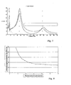
- the Fig. 7 shows an example of a typical frequency response of the built-up resonance, the test bed resonance and the axial resonance (from left to right).
- the amplitude of the built-up resonance has a maximum value between 1 and 2 Hz and the Achsresonanz has a maximum between 12 and 20 Hz. Due to these characteristic values for the resonance points of vehicles, it is expedient to design the test stand such that the test bed resonance lies between the maximum of the setup resonance and the axis resonance (typically at approximately 7 Hz).
- this spring-mass system e.g. is forced into a forced oscillation by a crank mechanism and thereby traverses the resonance frequency of the test setup, which is essentially determined by the spring-mass system of the contact plate, a resonant peak is formed, the stronger the weaker the system through the Shock absorber is damped.
- Lehr'sche damping measure is a quantity known from vibration theory that indicates how quickly an oscillation decays.
- the damping measure determined according to the invention characterizes the decay behavior or the resonance overshoot of a vibration of the vehicle body damped by the vibration damper (in contrast to the damping of a forced vibration of the contact plate and the vehicle wheel as in the prior art).
- a preferred degree of attenuation for characterizing the decay behavior is the Lehr's damping measure.
- Lehr's damping ratio can be based on a proportional Vehicle mass, with which the vibration damper is loaded, are performed. For vehicles with four wheels, this proportionate vehicle mass, which corresponds to the vehicle weight, which is supported on the respective vehicle, approximately one quarter of the total vehicle mass.
- the corresponding half permissible axle load can also be used as a proportionate vehicle mass. This is particularly advantageous because for many vehicles the permissible axle load, eg from the vehicle license, is known. In order to take into account the proportion of unsprung masses at the permissible axle load, this can be corrected with a factor (for example 0.9).
- the use of the permissible axle load has the advantage that the vehicle is considered under the condition of a maximum load and the vibration behavior for this case can be taken into account.
- the damping amount is determined by determining the actual proportionate vehicle mass m 4 for the vibration damper to be tested on the basis of a measurement.
- the proportionate vehicle mass m 4 is particularly suitable for a scale on which the respective vehicle wheel to be tested is placed. It is expedient to take into account the unsprung masses m 2 of the wheel and the suspension, since the measured weight of the total mass m 4 + m 2 corresponds. For simplicity it may be assumed in this case that about 10% of m 2 m 4. In this case, the measured value for the total mass acting on the footplate can be corrected by a factor of, for example, 0.9 in order to obtain a sufficiently accurate estimate for the proportionate vehicle mass m 4 .
- the balance is integrated in the testing device.
- the step for determining the proportionate vehicle mass for example, on the measurement of a lowering of the footprint plate by the load with the vehicle can be done. Due to the known spring constants of the support plate supporting spring elements so the proportionate vehicle mass m 4 can be determined without additional design effort.
- the damping measure according to the invention makes it possible to reliably test the functionality of shock absorbers, as is desirable, for example, for a main vehicle inspection. Based on an empirical study with different vehicles, it was found that functioning shock absorbers usually have a Lehr's damping ratio of ⁇ > 0.2.
- a corresponding compensation step may be provided.
- This compensation step is particularly useful for low attenuation constant vehicles, e.g. smaller vehicles with low vehicle weight, an advantage, since in this case the relative measurement error due to the friction damping in the test bench when determining the damping constant of the vibration is important.
- the damping constant K P of the test device can be determined, for example, by detecting the vibration amplitudes of the unloaded contact plate after completion of the excitation in a swing-out test. Since the damping constant K P of the test device is largely constant, it can be determined and stored once before the actual test of the shock absorber. To improve the accuracy and a parameter field for the damping constant K P , for example, depending on the load acting on the support plate or the vibration amplitude, determined and used for compensation. The evaluation of the decay test can be done, for example, with the help of the logarithmic decrement. In this way, the decay constant of the oscillation or the damping constant K P of the test stand can be determined directly on the basis of amplitude ratios in the swing-out test.
- An apparatus for determining an attenuation amount for vibrations of vehicles may include excitation means for exciting a vehicle a vehicle wheel connected to a vibration damper, detection means for detecting the movement of the excited vehicle wheel, first calculating means for determining a damping constant K of the vibration damper based on the detected movement of the vehicle wheel, and second calculating means for determining a damping amount for damping a vehicle vibration by the vibration damper.
- the device comprises a footprint on which the vehicle wheel rests.
- the uprising plate may be connected via an elastic element to a drive unit which periodically excites the contact plate. Due to the excitation, the footprint plate performs a vertical vibration which is transmitted to the upstanding vehicle wheel.
- Detection means can detect an amplitude of the movement of the contact plate. This preferably takes place in that corresponding sensors for determining the position or height of the contact plate are attached to the contact plate. Alternatively, the detection means may also directly detect the movement of the energized vehicle wheel. For this purpose, appropriate sensors may be mounted on the wheel or the suspension of the vehicle.
- the calculation means preferably determine the damping constant K of the vibration damper on the basis of the ratio A between an excitation amplitude r of the drive unit and the detected amplitude of the movement of the vehicle wheel or the contact plate in the case of resonance. Based on the measured amplitude of the movement of the spring-mass system of the contact plate and vehicle wheel in resonance the properties of the moving spring-mass system, such as the damping by the vibration damper, can be determined. By means of the relationships known from vibration theory, the damping constant K of the vibration damper can thus be determined.
- the calculation means determine the damping constant K taking into account the mass m 1 of the contact plate and the spring constant D 1 of the elastic element.
- the damping constant K for the respective vibration damper of the vehicle can be determined largely independently of the properties of the test apparatus.
- the judging means preferably determines the Lehr's damping measure for a vibration of the vehicle body on the basis of the determined damping constant K of the vibration damper.
- the device has vehicle mass determining means for determining the proportionate vehicle mass m 4 .
- the footprint of the test device may be supported via another elastic element, a so-called emphasizeddlingfeder, to carry a greater proportion of the vehicle mass and relieve the drive of the excitation means.
- the provision of the further elastic element also has the advantage that the contact plate does not drop so much when driving on the vehicle. This effect can also be used to determine the pro rata vehicle mass m 4 , in that the detection means detect the lowering of the contact plate due to the load on the proportionate vehicle mass m 4 .
- the proportionate vehicle mass m 4 can be determined exactly for each vehicle without an additional weighing device is necessary.
- the vehicle mass determination means determine the proportionate vehicle mass m 4 preferably taking into account the spring constant D 5 of the further elastic element and the spring constant D 1 of the elastic element.
- D D 1 + D 5 .
- judging means can judge the damping properties of the vibration damper by comparing the determined damping measure with a predetermined limit value G.
- the calculation means may comprise a compensation device which subtracts from the determined value for the damping constant K the damping constant K P of the test apparatus so as to obtain a corrected damping constant K 'of the vibration damper.
- the Fig. 2 shows a vibration model for a vehicle on a shock absorber tester with four masses m 1 to m 4 , where m 1 is the mass of the stand plate of the test stand, m 2 the unsprung masses of a vehicle wheel (wheel mass, axle mass, mass of the suspension, etc.), m 3 the mass of the shock absorber and m 4 represents the proportionate body mass of the vehicle.
- the respective deflections of the masses in their vibrations are denoted by x 0 to x 4 , where x 0 represents the deflection of the excitation, for example by a crank mechanism.
- the elastic elements shown as springs are the test bench spring between crank mechanism and test stand plate, the tire spring, the vehicle spring and the spring effect of the shock absorber eye.
- the corresponding spring constants are in this order with D 1 referred to D 4 .
- the damping constant of the vibration damper of the vehicle is denoted by K.
- x 1 is the amplitude of the swinging motion of the contact plate and f is the excitation frequency.
- ⁇ 0 the phase angle between the excitation vibration and the vibration of the contact plate is called.
- Fig. 3 illustrated simplified vibration model for a single-mass oscillator.
- m m 1 + m 2 .
- the determined value for the damping constant K applies to the conditions (speed v D , excitation amplitude r) under which the measurement was taken.
- the damping constant K for a shock absorber can be determined with sufficient accuracy.
- the Fig. 4 shows the amplitude curve of resonant vibrations at different levels of damping.
- the amplitude of a slightly damped oscillation strongly increases in the case of resonance.
- the damping amount ⁇ of the vibration it can be seen how from the measured amplitude ratio A of the degree of damping or the damping constant K of the vibration system can be determined.
- the damping constant K can be determined on the basis of the ascertained amplitude ratio A, the spring constant D 1 of the test bench spring and the plate mass m 1 of the test stand.
- the resonance peak of the forced vibration of the test stand is used to determine the damping of this vibration by the vibration damper of the vehicle or its damping constant K.
- the attenuation measure is used as a criterion for the evaluation of the vibration damper, in the present invention this represents only an intermediate step or an intermediate variable.
- the vehicle is now considered without a test bench and determined on the basis of the vehicle characteristics the Lehr'sche damping measure for the damping of vibration of the vehicle body by the vibration damper as a judgment measure.
- a vibration of the vehicle body with a proportionate vehicle mass m 4 and the vehicle spring D 3 is considered. This is determined by the vibration damper with the method according to the above method Damper constant K damped.
- ⁇ A of the bodywork between different vehicles usually has no major differences, this a predetermined known value can be assumed. This can be specified eg for different vehicle categories. Typical superstructure resonance frequencies for cars are 1.4 Hz, for off-road vehicles (SUVs) 1.6 Hz and for transporters 1.8 Hz.
- FIG. 12 is a flowchart for a method of determining a damping amount for vibration absorbers according to an embodiment of the present invention.
- step 100 the proportional vehicle mass m 4 with which the shock absorber to be tested is loaded is determined. This can be done by detecting the lowering of the contact plate by the load with the vehicle weight when the exciter drive is at rest after the vehicle has hit the upright plate.
- D the effective spring constant of the test bench and g is the gravitational acceleration.
- D D 1 + D 5 .
- the step for detecting the proportionate vehicle mass m 4 may also take place following the detection of the movement of the excited vehicle wheel or the determination of the damping constant K of the vibration damper.
- the vehicle wheel resting on the footboard would first be forced to vibrate forcibly, and then the weighing operation would take place.
- step 110 the wheel resting on the footprint plate is forced to vibrate forcibly.
- This is the uprising plate excited by an elastic element of a drive unit to vertical vibrations, wherein the excitation frequency is varied.
- the speed of the drive unit is slowly increased to pass through the resonance point.
- the excitation can also start at a higher speed, which is then slowly lowered until a resonance occurs.
- step 120 the movement of the energized vehicle wheel or the footprint plate is detected.
- a marking may be provided on the vehicle wheel, which is detected by corresponding sensors.
- step 130 the damping constant K of the vibration damper is determined on the basis of the detected movement of the vehicle wheel based on the relationship indicated in formula 2. As already explained, this calculation is based on the evaluation of the ratio between the excitation amplitude r and the detected amplitude x 1 the movement of the contact plate or the vehicle wheel in resonance.
- the determined value for the damping constant K is corrected in step 140.
- This compensation step is useful mainly for smaller or lighter vehicles with smaller damping constants, since for these vehicles, the test bench damping can be up to 15% of the total vibration damping.
- a swing-out test can be performed with an unloaded test bench.
- the uprising plate is excited by the drive unit to a vibration, and after switching off the drive unit of the amplitude characteristic of the damped oscillation is detected.
- the Fig. 5 shows a typical course of the vibration of the footwall in a swing-out attempt.
- the evaluation of the Ausschwings sheds preferably takes place with the help of the logarithmic decrement.
- the damping constant K P of the test bench is generally dependent on the respective disk amplitude (see Fig. 8 ), it is expedient to perform a swing-out test with the corresponding expected during operation of the test rig plate amplitude. It is also possible to determine beforehand the respective damping costs K P for different plate amplitudes and / or vehicle weights and to use the corresponding test bench damping constant K P for the measurement condition (eg plate amplitude) in the correction of the vibration damper constant. In any case, the damping food Ante or the damping constants K P of the dynamometer can be determined and stored (eg in a parameter field) in advance in setting up and calibration of the test stand and are in the implementation of the test method for vibration damper already exists.
- step 150 the Lehr'sche damping measure for the vibration of the vehicle body based on the corrected damping constant K ' is determined based on the formula. For this purpose, it is generally sufficient to assume a fixed resonance frequency ⁇ A for the vibration of the vehicle body. Furthermore, the proportional vehicle mass m 4 determined in this example in step 100 is included in the calculation. The determined damping measure ⁇ can be used as a criterion for assessing the resonance peaking or damping of the vibration of the vehicle body.
- step 160 the determined attenuation amount ⁇ is compared with a predetermined threshold value G, for example 0.1.
- G for example 0.1.
- step 160 If the test in step 160 indicates that the Lehr's damping amount of the vibration damper exceeds the predetermined limit value G, the vibration damper is declared functional in step 180.
- the tested vibration damper is declared a defective vibration damper in step 170, where appropriate appropriate action can be taken.
- the described method for determining a damping measure for vibrations of vehicles is thus suitable for testing built-in shock absorbers of motor vehicles and can be used, for example, in the context of a vehicle main inspection.
- the big advantage over known methods is that a meaningful, reliable assessment of the effectiveness of shock absorbers can be determined, which provides a reliable assessment measure, regardless of the type of vehicle to be tested and the properties of the test stand used.
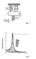
- the Fig. 1 schematically shows an embodiment of a shock absorber test stand according to the present invention.
- a vibration damper 1 a vehicle 2, a vehicle spring 12, a suspension 13 and a body of the vehicle 14 are shown schematically.
- the vibration model Fig. 2 corresponds to the damper 1, the damping constant K, of the vehicle spring 12, the spring constant D 3, of the wheel suspension 13, the unsprung wheel mass m 2 and the body 14 shown symbolically the proportional body mass m. 4
- the shock absorber test stand has a contact plate 7, a frame 8, a double rocker 9, a drive unit 4 and a first elastic element 3.
- the uprising plate 7 is connected via the double rocker 9 and the first elastic element 3 to the drive unit 4, which acts as a crank drive and causes the contact plate 7 and the vehicle wheel 2 to vibrate.
- a control unit 15 controls the rotational speed of the drive unit 4 in such a way that the oscillating system resonates.
- Another elastic element 6 supports the support plate 7 and carries a large part of the vehicle weight (typically between 60 and 90%) in order to avoid an excessive lowering of the contact plate 7 when loaded with the vehicle.
- Detecting means 5 which detect the movement of the contact plate 7 and supply a corresponding signal X to calculating means 10, 11, vehicle mass determining means 16 and the control unit 15, are provided in the vicinity of the standing plate 7. In the control unit 15, this signal X can be used to determine that the correct speed has been reached for resonating the oscillating system.
- Vehicle mass determining means 16 determine when the excitation is switched off on the basis of the reduction s of the contact plate 7 when the vehicle is approaching and the effective spring constant D is the proportionate vehicle mass m 4 .
- the second calculating means 11 determines the Lehr's damping amount ⁇ for vibration of the vehicle body based on the proportionate vehicle mass m 4 and the damping constant K of the vibration damper 1 (Formula 3).
- the evaluation means 17 provide the Functionality of the vibration damper 1 judged and generates a corresponding binary test signal indicating with "0" that the vibration damper 1 does not meet the test criterion, and indicates with "1” that the educaschwingungsdämpfer 1 has passed the test.
Landscapes
- Physics & Mathematics (AREA)
- General Physics & Mathematics (AREA)
- Measurement Of Mechanical Vibrations Or Ultrasonic Waves (AREA)
- Vibration Prevention Devices (AREA)
- Automobile Manufacture Line, Endless Track Vehicle, Trailer (AREA)
- Vehicle Body Suspensions (AREA)
Abstract
Description
Die Erfindung betrifft ein Verfahren und eine Vorrichtung zum Bestimmen eines Dämpfungsmaßes für Schwingungen von Fahrzeugen, die von einem Schwingungsdämpfer gedämpft werden.The invention relates to a method and an apparatus for determining a damping measure for vibrations of vehicles which are damped by a vibration damper.
Schwingungsdämpfer sind in Kraftfahrzeugen ein für die Verkehrssicherheit wichtiges Element. Zum einen muss verhindert werden, dass die Achsmassen mit Fahrzeug- bzw. Reifenfedern in unkontrollierte Schwingungen geraten, und zum anderen sollen die Schwingungen des Fahrzeugaufbaus gedämpft werden. Zu diesem Zweck sind an den Fahrzeugachsen Stoßdämpfer vorgesehen, die zusätzlich zur Eigendämpfung der Achse, z.B. durch Reibung oder Gummilager, auftretende Schwingungen unterdrücken. Bei der Abstimmung eines Stoßdämpfers sind grundsätzlich mehrere, gegenläufige Aspekte zu berücksichtigen. Einerseits nimmt in der Regel mit zunehmender Dämpfung die Radlastschwankung ab, andererseits wird jedoch der Fahrkomfort beeinträchtigt. Umgekehrt gilt, dass bei höherem Komfort auch höhere Radlastschwankungen in Kauf genommen werden müssen, was mit verminderter Bodenhaftung einhergeht.Vibration dampers are an important element in road safety in motor vehicles. On the one hand, it must be prevented that the axle masses with vehicle or tire springs in uncontrolled vibrations, and on the other hand, the vibrations of the vehicle body to be damped. For this purpose, shock absorbers are provided on the vehicle axles which, in addition to the self-damping of the axle, e.g. due to friction or rubber bearings, suppress vibrations that occur. When tuning a shock absorber, several opposing aspects must be considered. On the one hand decreases with increasing damping, the wheel load fluctuation, on the other hand, however, the ride comfort is impaired. Conversely, with greater comfort, even higher wheel load fluctuations must be accepted, which is associated with reduced traction.
Um einen guten Kompromiss mit möglichst wenig Radlastschwankungen, d.h. eine gute Straßenlage, und trotzdem hohen Komfort zu erreichen, können Stoßdämpfer mit variablen, nicht gleichmäßigen Kennlinien ausgebildet werden. Beispielsweise kann die Druckstufe schwächer ausgelegt werden als die Zugstufe und/oder der Dämpfer verfügt bei kleineren Geschwindigkeiten vD der Relativbewegung der bewegten Teile im Dämpfer über eine größere Dämpfungskonstante K als bei höheren Geschwindigkeiten, d.h. die Dämpfungskonstante weist eine nichtlineare Kennlinie auf. Um die Schwingungen des Fahrzeugaufbaus besser bedämpfen zu können, werden Stoßdämpfer teilweise so ausgelegt, dass die Dämpferkraft FD bei kleinen Geschwindigkeiten stark ansteigt und ab ca. 0,1 bis 0,2 m/s flacher wird. Für die Dämpfungskonstante K eines Stoßdämpfers gilt
Bei derartigen nicht-linearen Dämpfern ist die Dämpfungskonstante K bei kleinen Geschwindigkeiten größer und nimmt bei größeren Geschwindigkeiten ab. Insbesondere bei Fahrzeugen, die mit Blockierverhinderungssystemen bzw. Stabilitätssystemen ausgestattet sind, ist der Einfluss der Fahrzeugdämpfung für die richtige Funktion der Fahrhilfesysteme bedeutsam. Beispiele für Stoßdämpferkennlinien sind in
Zur Überprüfung der Wirkung von Kraftfahrzeug-Stoßdämpfern in eingebautem Zustand sind eine Reihe von Prüfverfahren bekannt.To verify the effect of motor vehicle shock absorbers in the installed state, a number of test methods are known.
In der
Um die Führung der Aufstandsplatte und den Exzenterantrieb zur Erregung des Systems von dem Fahrzeuggewicht zu entlasten, wird in der
Die
Wird nun dieses Feder-Masse-System z.B. durch einen Kurbeltrieb in eine erzwungene Schwingung versetzt und dabei die Resonanzfrequenz des Prüfaufbaus, welche im Wesentlichen durch das Feder-Masse-System der Aufstandsplatte bestimmt wird, durchfahren, so bildet sich eine Resonanzüberhöhung, die um so stärker ist, je schwächer das System durch den Stoßdämpfer bedämpft wird.Now, if this spring-mass system, e.g. is forced into a forced oscillation by a crank mechanism and thereby traverses the resonance frequency of the test setup, which is essentially determined by the spring-mass system of the contact plate, a resonant peak is formed, the stronger the weaker the system through the Shock absorber is damped.
In der
Grundsätzlich haben alle bekannten Verfahren zur Beurteilung von Schwingungsdämpfern den Nachteil, dass sie eigentlich eine durch eine Erregung erzwungene und durch den Fahrzeugdämpfer gedämpfte Schwingung eines schwingenden Systems bestehend aus Aufstandsplatte und Fahrzeugrad mit Aufhängung betrachten und auswerten. Mit anderen Worten wird, unter der Annahme eines feststehenden Fahrzeugaufbaus, die Dämpfung ermittelt, mit welcher der Fahrzeugdämpfer den Schwinger des Prüfstands (d.h. die Aufstandsplatte) bedämpft. Ein derartig ermitteltes Dämpfungsmaß ist jedoch nicht zu einer Beurteilung der eigentlich interessanteren Dämpfung geeignet, mit welcher der Stoßdämpfer den Fahrzeugaufbau bedämpft.Basically, all known methods for the evaluation of vibration dampers have the disadvantage that they actually consider a forced by an excitation and attenuated by the vehicle damper vibration of a vibrating system consisting of footprint and vehicle wheel with suspension and evaluate. In other words, assuming a fixed vehicle body, the damping at which the vehicle damper dampens the vibrator of the test stand (i.e., the footprint plate) is determined. However, a damping measure determined in this way is not suitable for assessing the actually more interesting damping with which the shock absorber damps the vehicle body.
Es ist die Aufgabe der vorliegenden Erfindung, ein Beurteilungsmaß für die Dämpfung von Fahrzeugschwingungen durch Schwingungsdämpfer bereitzustellen, das eine zuverlässige Beurteilung der Wirksamkeit von Schwingungsdämpfern im eingebauten Zustand ermöglicht, und ein entsprechendes Verfahren und eine geeignete Vorrichtung zu dessen Ermittlung vorzusehen.It is the object of the present invention to provide a judgment measure for the damping of vehicle vibrations by vibration damper, which allows a reliable assessment of the effectiveness of vibration dampers in the installed state, and to provide a corresponding method and apparatus for its determination.
Diese Aufgabe wird erfindungsgemäß durch die unabhängigen Ansprüche gelöst. Die abhängigen Ansprüche betreffen vorteilhafte Ausführungsformen der Erfindung.This object is achieved by the independent claims. The dependent claims relate to advantageous embodiments of the invention.
Ein erfindungsgemäßes Verfahren zum Bestimmen eines Dämpfungsmaßes für Schwingungen von Fahrzeugen kann die folgenden Schritte aufweisen.
- Erregen eines, mit einem zu beurteilenden Schwingungsdämpfer verbundenen Fahrzeugrades.
Durch die Erregung wird das Fahrzeugrad und der Schwingungsdämpfer in eine Schwingung versetzt, wobei die auftretende Schwingung durch den Schwingungsdämpfer bedämpft wird. Vorzugsweise erfolgt eine vertikale, periodische Erregung, beispielsweise durch eine Aufstandsplatte, auf welcher das Fahrzeugrad aufsteht. Zweckmäßigerweise erfolgt die Erregung derart, dass eine Resonanz des bewegten Feder-Masse-Systems erreicht wird. Hierzu kann beispielsweise die Erregung mittels einer veränderlichen Frequenz erfolgen, die, ausgehend von einer Startfrequenz, langsam erhöht wird, bis eine entsprechende Resonanz auftritt. Selbstverständlich kann das Verfahren auch von einer höheren Frequenz ausgehen und die Erregungsfrequenz solange verringern, bis ein Resonanzeffekt auftritt. - Erfassen der Bewegung des erregten Fahrzeugrades oder der Aufstandsplatte, auf der das Rad aufsteht.
Zweckmäßigerweise wird die Amplitude x̂ der erzwungenen Schwingung von Fahrzeugrad bzw. von der Aufstandsplatte mittels geeigneter Sensoren ermittelt. Diese können beispielsweise die Bewegung des Rads anhand einer daran angebrachten Markierung optisch erfassen. Da der Fahrzeugreifen durch die Reifenfeder eine Federwirkung aufweisen kann, ist es möglich, dass die Bewegungen von Radaufhängung und Schwingungsdämpfer nicht identisch mit der Bewegung der Aufstandsplatte verlaufen. Die am Schwingungsdämpfer auftretende Bewegungsamplitude kann deshalb, z.B. mittels eines Korrekturfaktors, aus der eventuell einfacher zu erfassenden Amplitude der Aufstandsplatte bestimmt werden, wobei die Federwirkung der Reifenfeder in dem Korrekturfaktor berücksichtigt werden kann. Grundsätzlich ist es für die vorliegende Erfindung möglich, sowohl die Bewegung des Rades als auch die Bewegung der Aufstandsplatte zu erfassen und auszuwerten. - Ermitteln der Dämpfungskonstante K des Schwingungsdämpfers anhand der erfassten Bewegung des Fahrzeugrads bzw. der Aufstandsplatte.
Dies geschieht vorzugsweise anhand des Verhältnisses A zwischen einer Amplitude r der Erregung und der erfassten Amplitude x̂ 1 der Bewegung des Fahrzeugrads bzw. der Aufstandsplatte im Resonanzfall: A = r/ x̂ 1̂. Bei diesem Verfahrensschritt wird die Bedämpfung der erzwungenen Schwingung von Aufstandsplatte und Fahrzeugrad durch den Schwingungsdämpfer dahingehend ausgewertet, um die Dämpfungskonstante K des Schwingungsdämpfers zu ermitteln. Da die Karosseriemasse des Fahrzeugs in der Regel sehr viel größer ist als die durch die Erregung bewegte Masse, kann der Karosserieaufbau als in Ruhe (feststehend) betrachtet werden. In diesem Fall ist es zweckmäßig, von einem Ein-Massen-Schwingungs-System auszugehen. Der Zusammenhang zwischen Dämpfungskonstante K des Schwingungsdämpfers und dem Amplitudenverhältnis A kann beispielsweise über den Energieerhaltungssatz bestimmt werden. Dabei wird angenommen, dass die von der Erregung in das System eingespeiste Energie bzw. Leistung vom Schwingungsdämpfer aufgenommen und absorbiert wird.
Da vorzugsweise die Erregung des Fahrzeugrads bzw. der Aufstandsplatte über ein elastisches Element erfolgt, kann die Dämpfungskonstante K des Schwingungsdämpfers anhand der Federkonstanten D1 des elastischen Elements, des Amplitudenverhältnisses A und der Resonanzfrequenz ω0 gemäß folgender Formel ermittelt werden:
Die Resonanzfrequenz ω0 = 2π·f0 für das schwingende System kann beispielsweise durch Auswertung der Amplituden x̂ 1 bestimmt werden, da bei ω0 ein leicht zu erkennendes Maximum der Amplitude auftritt.
Zu einem ähnlichen Ergebnis gelangt man auch über eine Betrachtung der Maschinendynamik unter Berücksichtigung des Lehr'schen Dämpfungsmaßes für Schwingungen. Die Dämpfungskonstante K kann anhand der schwingenden Masse m (Masse m1 der Aufstandsplatte und ungefederte Masse m2 des Rads) der Federkonstanten D1 des elastischen Elements der Federkonstanten D3 der Fahrzeugfeder und des Amplitudenverhältnisses A ermittelt werden. Da m1 >> m2 und D1 >> D3 gilt, kann die Dämpfungskonstante K ohne eine explizite Kenntnis der Resonanzfrequenz des schwingenden Systems ermittelt werden:
In diesem Zusammenhang sei angemerkt, dass in der vorliegenden Erfindung das Lehr'sche Dämpfungsmaß für die erzwungene gemeinsame Schwingung von Aufstandsplatte und Rad nur dazu verwendet wird, die Dämpfungskonstante K des Schwingungsdämpfers zu ermitteln, während bei den bekannten Prüfverfahren nach dem Stand der Technik das Lehr'sche Dämpfungsmaß für die Dämpfung der Schwingung des Prüfstands mit dem Fahrzeugrad als abschließendes Beurteilungskriterium für den Schwingungsdämpfer des Fahrzeugs herangezogen wird. - Ermitteln eines Dämpfungsmaßes für die Bedämpfung einer Schwingung der Fahrzeugkarosserie durch den Schwingungsdämpfer anhand der ermittelten Dämpfungskonstante K des Dämpfers.
Gemäß der vorliegenden Erfindung wird basierend auf der ermittelten Dämpfungskonstante K ein Maß für die Bedämpfung einer Fahrzeugschwingung durch den Schwingungsdämpfer bestimmt. Dieses Dämpfungsmaß ist unabhängig von den Eigenschaften des Prüfaufbaus, wie der Masse m1 der Aufstandsplatte und der Federkonstante D1 des elastischen Elements. Deshalb eignet sich dieses Dämpfungsmaß besser als Beurteilungsmaß für die Funktionsfähigkeit des Schwingungsdämpfers als die bekannten Dämpfungsmaße.
- Exciting a vehicle wheel connected to a vibration damper to be assessed.
As a result of the excitation, the vehicle wheel and the vibration damper are set in vibration, whereby the occurring vibration is damped by the vibration damper. Preferably, there is a vertical, periodic excitation, for example, by an uprising plate on which the vehicle wheel rests. Appropriately, the excitation takes place in such a way that a resonance of the moving spring-mass system is achieved. For this purpose, for example, the excitation by means of a variable frequency, which, starting from a start frequency, is slowly increased until a corresponding resonance occurs. Of course, the method can also start from a higher frequency and reduce the excitation frequency until a resonance effect occurs. - Detecting the movement of the energized vehicle wheel or the footprint on which the wheel stands up.
The amplitude x of the forced vibration of the vehicle wheel or of the contact plate is expediently determined by means of suitable sensors. These can, for example, optically detect the movement of the wheel on the basis of a marking attached thereto. Since the vehicle tire may have a spring action by the tire spring, it is possible that the movements of the suspension and the vibration damper are not identical with the movement of the contact plate. The amplitude of movement occurring at the vibration damper can therefore be determined, for example by means of a correction factor, from the possibly easier to detect amplitude of the contact plate, wherein the spring action of the tire spring can be taken into account in the correction factor. in principle For example, it is possible for the present invention to detect and evaluate both the movement of the wheel and the movement of the footprint plate. - Determining the damping constant K of the vibration damper on the basis of the detected movement of the vehicle wheel or the contact plate.
This preferably takes place on the basis of the ratio A between an amplitude r of the excitation and the detected amplitude x 1 of the movement of the vehicle wheel or of the contact plate in the case of resonance: A = r / x 1 . In this method step, the damping of the forced vibration of the contact plate and the vehicle wheel by the vibration damper is evaluated to determine the damping constant K of the vibration damper. Since the body mass of the vehicle is usually much larger than the mass moved by the excitation, the bodywork may be considered at rest (fixed). In this case, it is expedient to start from a one-mass vibration system. The relationship between the damping constant K of the vibration damper and the amplitude ratio A can be determined, for example, via the energy conservation law. It is assumed that the energy or power supplied by the excitation into the system is absorbed and absorbed by the vibration damper.
Since preferably the excitation of the vehicle wheel or the footprint plate via an elastic element, the damping constant K of the vibration damper on the basis of the spring constant D1 of the elastic element, the amplitude ratio A and the resonance frequency ω 0 are determined according to the following formula:
The resonant frequency ω 0 = 2π · f 0 for the oscillating system can be determined, for example, by evaluating the amplitudes x 1 , since at ω 0 an easily recognizable maximum of the amplitude occurs.
A similar result can be obtained by considering machine dynamics taking into account Lehr's damping measure for vibrations. The damping constant K can be determined on the basis of the oscillating mass m (mass m 1 of the contact plate and unsprung mass m 2 of the wheel) of the spring constant D 1 of the elastic element of the spring constant D 3 of the vehicle spring and the amplitude ratio A. Since m 1 >> m 2 and D 1 >> D 3 , the damping constant K can be determined without an explicit knowledge of the resonant frequency of the oscillating system:
In this connection, it should be noted that in the present invention, the Lehr's damping ratio for the forced common vibration of the footplate and wheel is used only to determine the damping constant K of the vibration damper, while in the known test methods according to the prior art, the Lehr's damping factor for the damping of the vibration of the test stand with the vehicle wheel is used as a final assessment criterion for the vibration damper of the vehicle. - Determining a damping measure for the damping of a vibration of the vehicle body by the vibration damper on the basis of the determined damping constant K of the damper.
According to the present invention, based on the determined damping constant K, a measure of the damping of vehicle vibration by the vibration damper is determined. This degree of damping is independent of the properties of the test structure, such as the mass m 1 of the contact plate and the spring constant D 1 of the elastic element. Therefore, this attenuation measure is better suited as a measure of judgment for the functioning of the vibration damper than the known attenuation measurements.
Vorzugsweise charakterisiert das erfindungsgemäß ermittelte Dämpfungsmaß das Abklingverhalten bzw. die Resonanzüberhöhung einer durch den Schwingungsdämpfer bedämpften Schwingung des Fahrzeugaufbaus (im Gegensatz zu der Dämpfung einer erzwungenen Schwingung von Aufstandsplatte und Fahrzeugrad wie im Stand der Technik). Ein bevorzugtes Dämpfungsmaß zur Charakterisierung des Abklingverhaltens ist das Lehr'sche Dämpfungsmaß.Preferably, the damping measure determined according to the invention characterizes the decay behavior or the resonance overshoot of a vibration of the vehicle body damped by the vibration damper (in contrast to the damping of a forced vibration of the contact plate and the vehicle wheel as in the prior art). A preferred degree of attenuation for characterizing the decay behavior is the Lehr's damping measure.
Zur Beurteilung der Dämpfung von Fahrzeugschwingungen kann die Berechnung des Lehrschen Dämpfungsmaßes anhand einer anteiligen Fahrzeugmasse, mit welcher der Schwingungsdämpfer belastet wird, ausgeführt werden. Bei Fahrzeugen mit vier Rädern entspricht diese anteilige Fahrzeugmasse, die dem Fahrzeuggewicht entspricht, das sich auf das jeweilige Fahrzeugrad abstützt, ungefähr einem Viertel der gesamten Fahrzeugmasse. Um unterschiedliche Lasten zwischen den Fahrzeugachsen zu berücksichtigen kann auch die entsprechende halbe zulässige Achslast als anteilige Fahrzeugmasse herangezogen werden. Dies ist besonders vorteilhaft, da für viele Fahrzeuge die zulässige Achslast, z.B. aus dem Kraftfahrzeugschein, bekannt ist. Um den Anteil der ungefederten Massen an der zulässigen Achslast zu berücksichtigen, kann diese mit einem Faktor (beispielsweise 0,9) korrigiert werden. Die Verwendung der zulässigen Achslast hat den Vorteil, daß das Fahrzeug unter der Bedingung einer maximalen Beladung betrachtet wird und das Schwingungsverhalten für diesen Fall berücksichtigt werden kann.To assess the damping of vehicle vibrations, the calculation of Lehr's damping ratio can be based on a proportional Vehicle mass, with which the vibration damper is loaded, are performed. For vehicles with four wheels, this proportionate vehicle mass, which corresponds to the vehicle weight, which is supported on the respective vehicle, approximately one quarter of the total vehicle mass. In order to take account of different loads between the vehicle axles, the corresponding half permissible axle load can also be used as a proportionate vehicle mass. This is particularly advantageous because for many vehicles the permissible axle load, eg from the vehicle license, is known. In order to take into account the proportion of unsprung masses at the permissible axle load, this can be corrected with a factor (for example 0.9). The use of the permissible axle load has the advantage that the vehicle is considered under the condition of a maximum load and the vibration behavior for this case can be taken into account.
Erfindungsgemäß wird das Dämpfungsmaß ermittelt, indem die tatsächliche anteilige Fahrzeugmasse m4 für den zu prüfenden Schwingungsdämpfer anhand einer Messung ermittelt wird. Zur Messung der anteiligen Fahrzeugmasse m4 eignet sich insbesondere eine Waage, auf die das jeweilige zu prüfende Fahrzeugrad aufgestellt wird. Hierbei ist es zweckmäßig, die ungefederten Massen m2 des Rades und der Radaufhängung zu berücksichtigen, da das gemessene Gewicht der Gesamtmasse m4+m2 entspricht. Zur Vereinfachung kann hierbei angenommen werden, dass m2 etwa 10 % von m4 beträgt. In diesem Fall kann der gemessene Wert für die auf die Aufstandsplatte wirkende Gesamtmasse mit einem Faktor, von z.B. 0,9 korrigiert werden, um eine ausreichend genaue Abschätzung für die anteilige Fahrzeugmasse m4 zu erhalten.According to the invention, the damping amount is determined by determining the actual proportionate vehicle mass m 4 for the vibration damper to be tested on the basis of a measurement. For measuring the proportionate vehicle mass m 4 is particularly suitable for a scale on which the respective vehicle wheel to be tested is placed. It is expedient to take into account the unsprung masses m 2 of the wheel and the suspension, since the measured weight of the total mass m 4 + m 2 corresponds. For simplicity it may be assumed in this case that about 10% of m 2 m 4. In this case, the measured value for the total mass acting on the footplate can be corrected by a factor of, for example, 0.9 in order to obtain a sufficiently accurate estimate for the proportionate vehicle mass m 4 .
Erfindungsgemäß ist die Waage in die Prüfvorrichtung integriert. In diesem Fall kann der Schritt zur Ermittlung der anteiligen Fahrzeugmasse beispielsweise auf der Messung einer Absenkung der Aufstandsplatte durch die Belastung mit dem Fahrzeug erfolgen. Aufgrund der bekannten Federkonstanten der die Aufstandsplatte abstützenden Federelemente kann so die anteilige Fahrzeugmasse m4 ohne zusätzlichen konstruktiven Aufwand ermittelt werden.According to the invention, the balance is integrated in the testing device. In this case, the step for determining the proportionate vehicle mass, for example, on the measurement of a lowering of the footprint plate by the load with the vehicle can be done. Due to the known spring constants of the support plate supporting spring elements so the proportionate vehicle mass m 4 can be determined without additional design effort.
Bei bekannter Federkonstante D3 der Fahrzeugfeder lässt sich so das Lehr'sche Dämpfungsmaß für das Fahrzeug gemäß folgender Formel: 
Da das erfindungsgemäß ermittelte Dämpfungsmaß weitgehend unabhängig von den Eigenschaften der verwendeten Prüfvorrichtung ist und die Dämpfungseigenschaften für Fahrzeugschwingungen korrekt charakterisiert, kann es zur verlässlichen und reproduzierbaren Beurteilung von Schwingungsdämpfern herangezogen werden. Trotz einer unterschiedlichen Abstimmung von Fahrzeugen ermöglicht das erfindungsgemäße Dämpfungsmaß eine zuverlässige Prüfung der Funktionsfähigkeit von Stoßdämpfern, wie sie z.B. für eine Fahrzeughauptuntersuchung wünschenswert ist. Aufgrund einer empirischen Untersuchung mit verschiedenen Fahrzeugen wurde festgestellt, dass funktionsfähige Stoßdämpfer in der Regel ein Lehr'sches Dämpfungsmaß von ϑ > 0,2 aufweisen.Since the inventively determined Dämpfungsmaß is largely independent of the properties of the test apparatus used and The damping characteristics for vehicle vibrations correctly characterized, it can be used for reliable and reproducible assessment of vibration dampers. Despite a different tuning of vehicles, the damping measure according to the invention makes it possible to reliably test the functionality of shock absorbers, as is desirable, for example, for a main vehicle inspection. Based on an empirical study with different vehicles, it was found that functioning shock absorbers usually have a Lehr's damping ratio of θ > 0.2.
Vorzugsweise weist das erfindungsgemäße Verfahren einen weiteren Beurteilungsschritt zum Beurteilen der Dämpfungseigenschaften des Schwingungsdämpfers auf, wobei das für den zu prüfenden Schwingungsdämpfer ermittelte Dämpfungsmaß ϑ mit einem vorgegebenen Grenzwert G verglichen wird. Unterschreitet das erfindungsgemäß ermittelte Lehr'sche Dämpfungsmaß ϑ für den Schwingungsdämpfer beispielsweise einen vorgegebenen Grenzwert G = 0,1, so ist davon auszugehen, dass der Schwingungsdämpfer nicht mehr ausreichend zu einer Bedämpfung einer Schwingung des Fahrzeugs geeignet ist und seine Funktion deshalb nicht mehr ausreichend füllt. In diesem Fall ist der Schwingungsdämpfer als defekt zu beurteilen und auszutauschen.Preferably, the method according to the invention has a further assessment step for assessing the damping properties of the vibration damper, wherein the damping factor θ determined for the vibration damper to be tested is compared with a predetermined limit value G. If the Lehr'sche Dämpfungsmaß θ for the vibration damper, for example, falls below a predetermined limit G = 0.1, it is to be assumed that the vibration damper is no longer sufficiently suitable for damping vibration of the vehicle and therefore no longer adequately fills its function , In this case, the vibration damper is to be assessed as defective and replaced.
Um Dämpfungsverluste der Prüfvorrichtung durch Reibung bei der Ermittlung der Dämpfungskonstante K des Schwingungsdämpfers zu kompensieren, kann ein entsprechender Kompensationsschritt vorgesehen sein. Bei der Kompensation wird vorzugsweise eine korrigierte Dämpfungskonstante K' des Fahrzeugs ermittelt, indem der anhand der erfassten Bewegung des Fahrzeugrads bzw. Aufstandsplatte ermittelte Wert für die Dämpfungskonstante K mit einer Schwingungsdämpfungskonstante KP des Prüfstands korrigiert wird. In der Regel erfolgt dies durch Subtraktion der Dämpfungskonstante KP des Prüfstands von dem anhand des Schwingungsversuchs ermittelten Wert: K' = K - KP.In order to compensate for damping losses of the testing device by friction in the determination of the damping constant K of the vibration damper, a corresponding compensation step may be provided. In the compensation, a corrected damping constant K 'of the vehicle is preferably determined by the determined based on the detected movement of the vehicle wheel or footprint plate Value for the damping constant K is corrected with a vibration damping constant K P of the test bench. As a rule, this is done by subtracting the damping constant K P of the test bench from the value determined on the basis of the vibration test: K '= K - K P.
Dieser Kompensationsschritt ist insbesondere für Fahrzeuge mit geringer Dämpfungskonstante, wie z.B. kleinere Fahrzeuge mit geringem Fahrzeuggewicht, von Vorteil, da in diesem Fall der relative Messfehler durch die Reibungsdämpfung im Prüfstand bei der Ermittlung der Dämpfungskonstante des Schwingungsdämpfers von Bedeutung ist.This compensation step is particularly useful for low attenuation constant vehicles, e.g. smaller vehicles with low vehicle weight, an advantage, since in this case the relative measurement error due to the friction damping in the test bench when determining the damping constant of the vibration is important.
Die Dämpfungskonstante KP der Prüfvorrichtung kann beispielsweise durch Erfassung der Schwingungsamplituden der unbelasteten Aufstandsplatte nach dem Abschluss der Erregung in einem Ausschwingversuch ermittelt werden. Da die Dämpfungskonstante KP der Prüfvorrichtung weitgehend konstant ist, kann sie einmal vor der eigentlichen Prüfung des Stoßdämpfers bestimmt und gespeichert werden. Zur Verbesserung der Genauigkeit kann auch ein Parameterfeld für die Dämpfungskonstante KP, beispielsweise abhängig von der auf die Aufstandsplatte wirkenden Last oder der Schwingungsamplitude, ermittelt und zur Kompensation herangezogen werden. Die Auswertung des Ausschwingversuches kann beispielsweise mit Hilfe des logarithmischen Dekrements erfolgen. Auf diese Weise kann anhand von Amplitudenverhältnissen im Ausschwingversuch direkt die Abklingkonstante der Schwingung bzw. die Dämpfungskonstante KP des Prüfstands bestimmt werden.The damping constant K P of the test device can be determined, for example, by detecting the vibration amplitudes of the unloaded contact plate after completion of the excitation in a swing-out test. Since the damping constant K P of the test device is largely constant, it can be determined and stored once before the actual test of the shock absorber. To improve the accuracy and a parameter field for the damping constant K P , for example, depending on the load acting on the support plate or the vibration amplitude, determined and used for compensation. The evaluation of the decay test can be done, for example, with the help of the logarithmic decrement. In this way, the decay constant of the oscillation or the damping constant K P of the test stand can be determined directly on the basis of amplitude ratios in the swing-out test.
Eine Vorrichtung zum Bestimmen eines Dämpfungsmaßes für Schwingungen von Fahrzeugen kann Erregungsmittel zum Erregen eines mit einem Schwingungsdämpfer verbundenen Fahrzeugrades, Erfassungsmittel zum Erfassen der Bewegung des erregten Fahrzeugrades, erste Berechnungsmittel zum Ermitteln einer Dämpfungskonstante K des Schwingungsdämpfers anhand der erfassten Bewegung des Fahrzeugrades und zweite Berechnungsmittel zum Ermitteln eines Dämpfungsmaßes für die Bedämpfung einer Fahrzeugschwingung durch den Schwingungsdämpfer aufweisen.An apparatus for determining an attenuation amount for vibrations of vehicles may include excitation means for exciting a vehicle a vehicle wheel connected to a vibration damper, detection means for detecting the movement of the excited vehicle wheel, first calculating means for determining a damping constant K of the vibration damper based on the detected movement of the vehicle wheel, and second calculating means for determining a damping amount for damping a vehicle vibration by the vibration damper.
Vorzugsweise umfasst die Vorrichtung eine Aufstandsplatte, auf der das Fahrzeugrad aufsteht. Die Aufstandsplatte kann über ein elastisches Element mit einer Antriebseinheit verbunden sein, welche die Aufstandsplatte periodisch erregt. Aufgrund der Erregung führt die Aufstandsplatte eine vertikale Schwingung aus, welche auf das aufstehende Fahrzeugrad übertragen wird.Preferably, the device comprises a footprint on which the vehicle wheel rests. The uprising plate may be connected via an elastic element to a drive unit which periodically excites the contact plate. Due to the excitation, the footprint plate performs a vertical vibration which is transmitted to the upstanding vehicle wheel.
Erfassungsmittel können eine Amplitude der Bewegung der Aufstandsplatte erfassen. Dies geschieht vorzugsweise dadurch, dass an der Aufstandsplatte entsprechende Sensoren zur Ermittlung der Position bzw. Höhe der Aufstandsplatte angebracht sind. Alternativ können die Erfassungsmittel auch direkt die Bewegung des erregten Fahrzeugrades erfassen. Hierzu können entsprechende Sensoren am Rad bzw. der Radaufhängung des Fahrzeugs angebracht sein.Detection means can detect an amplitude of the movement of the contact plate. This preferably takes place in that corresponding sensors for determining the position or height of the contact plate are attached to the contact plate. Alternatively, the detection means may also directly detect the movement of the energized vehicle wheel. For this purpose, appropriate sensors may be mounted on the wheel or the suspension of the vehicle.
Die Berechnungsmittel bestimmen die Dämpfungskonstante K des Schwingungsdämpfers vorzugsweise anhand des Verhältnisses A zwischen einer Erregungsamplitude r der Antriebseinheit und der erfassten Amplitude der Bewegung des Fahrzeugrades bzw. der Aufstandsplatte im Resonanzfall. Anhand der gemessenen Amplitude der Bewegung des Feder-Masse-Systems aus Aufstandsplatte und Fahrzeugrad im Resonanzfall können die Eigenschaften des bewegten Feder-Masse-Systems, wie die Bedämpfung durch den Schwingungsdämpfer, bestimmt werden. Mittels der aus der Schwingungslehre bekannten Zusammenhänge kann so die Dämpfungskonstante K des Schwingungsdämpfers bestimmt werden.The calculation means preferably determine the damping constant K of the vibration damper on the basis of the ratio A between an excitation amplitude r of the drive unit and the detected amplitude of the movement of the vehicle wheel or the contact plate in the case of resonance. Based on the measured amplitude of the movement of the spring-mass system of the contact plate and vehicle wheel in resonance the properties of the moving spring-mass system, such as the damping by the vibration damper, can be determined. By means of the relationships known from vibration theory, the damping constant K of the vibration damper can thus be determined.
Vorzugsweise ermitteln die Berechnungsmittel die Dämpfungskonstante K unter Berücksichtigung der Masse m1 der Aufstandsplatte und der Federkonstanten D1 des elastischen Elements. Auf diese Weise kann die Dämpfungskonstante K für den jeweiligen Schwingungsdämpfer des Fahrzeugs weitgehend unabhängig von den Eigenschaften der Prüfvorrichtung ermittelt werden.Preferably, the calculation means determine the damping constant K taking into account the mass m 1 of the contact plate and the spring constant D 1 of the elastic element. In this way, the damping constant K for the respective vibration damper of the vehicle can be determined largely independently of the properties of the test apparatus.
Die Beurteilungsmittel bestimmen bevorzugt das Lehr'sche Dämpfungsmaß für eine Schwingung der Fahrzeugkarosserie anhand der ermittelten Dämpfungskonstante K des Schwingungsdämpfers.The judging means preferably determines the Lehr's damping measure for a vibration of the vehicle body on the basis of the determined damping constant K of the vibration damper.
Zweckmäßigerweise weist die Vorrichtung Fahrzeugmassebestimmungsmittel zum Ermitteln der anteiligen Fahrzeugmasse m4 auf.Expediently, the device has vehicle mass determining means for determining the proportionate vehicle mass m 4 .
Die Aufstandsplatte der Prüfvorrichtung kann über ein weiteres elastisches Element, eine sogenannte Fußpunktfeder, abgestützt sein, um einen größeren Anteil der Fahrzeugmasse zu tragen und den Antrieb der Erregungsmittel zu entlasten. Das Vorsehen des weiteren elastischen Elements hat zudem den Vorteil, dass die Aufstandsplatte beim Auffahren des Fahrzeugs nicht so stark absinkt. Dieser Effekt kann auch zur Ermittelung der anteiligen Fahrzeugmasse m4 genutzt werden, indem die Erfassungsmittel die Absenkung der Aufstandsplatte bedingt durch die Belastung mit der anteiligen Fahrzeugmasse m4 erfassen. Durch eine derartige Gestaltung der Prüfvorrichtung kann die anteilige Fahrzeugmasse m4 für jedes Fahrzeugrad genau bestimmt werden, ohne dass eine zusätzliche Wiegevorrichtung notwendig wird.The footprint of the test device may be supported via another elastic element, a so-called Fußpunktfeder, to carry a greater proportion of the vehicle mass and relieve the drive of the excitation means. The provision of the further elastic element also has the advantage that the contact plate does not drop so much when driving on the vehicle. This effect can also be used to determine the pro rata vehicle mass m 4 , in that the detection means detect the lowering of the contact plate due to the load on the proportionate vehicle mass m 4 . By a Such design of the test apparatus, the proportionate vehicle mass m 4 can be determined exactly for each vehicle without an additional weighing device is necessary.
Die Fahrzeugmassebestimmungsmittel ermitteln die anteilige Fahrzeugmasse m4 vorzugsweise unter Berücksichtigung der Federkonstanten D5 des weiteren elastischen Elements und der Federkonstanten D1 des elastischen Elements. Für die effektive Federkonstante D des Prüfstands gilt: D = D1 + D5.The vehicle mass determination means determine the proportionate vehicle mass m 4 preferably taking into account the spring constant D 5 of the further elastic element and the spring constant D 1 of the elastic element. For the effective spring constant D of the test bench: D = D 1 + D 5 .
Um die Funktionsfähigkeit des zu prüfenden Schwingungsdämpfers festzustellen, können Beurteilungsmittel die Dämpfungseigenschaften des Schwingungsdämpfers beurteilen, indem das ermittelte Dämpfungsmaß mit einem vorgegebenen Grenzwert G verglichen wird.In order to determine the operability of the vibration damper to be tested, judging means can judge the damping properties of the vibration damper by comparing the determined damping measure with a predetermined limit value G.
Zur Kompensation der Schwingungsdämpfung durch Reibung in der Prüfvorrichtung können die Berechnungsmittel eine Kompensationsvorrichtung aufweisen, welche von dem ermittelten Wert für die Dämpfungskonstante K die Dämpfungskonstante KP der Prüfvorrichtung subtrahieren, um so eine korrigierte Dämpfungskonstante K' des Schwingungsdämpfers zu erhalten.To compensate for the vibration damping by friction in the test apparatus, the calculation means may comprise a compensation device which subtracts from the determined value for the damping constant K the damping constant K P of the test apparatus so as to obtain a corrected damping constant K 'of the vibration damper.
Weitere Besonderheiten und Vorzüge der Erfindung lassen sich den Zeichnungen und der folgenden Beschreibung bevorzugter Ausführungsbeispiele entnehmen. Es zeigen:
-
Fig. 1 schematisch ein Ausführungsbeispiel für einen Stoßdämpferprüfstand nach der vorliegenden Erfindung, -
Fig. 2 ein Schwingungsmodell für ein Fahrzeug auf einem Stoßdämpferprüfstand mit vier Massen, -
Fig. 3 ein vereinfachtes Schwingungsmodell für einen Ein-Masse-Schwinger, -
Fig. 4 den Amplitudenverlauf von Resonanzschwingungen bei verschiedenen Dämpfungsgraden, -
Fig. 5 einen typischen Verlauf der Schwingung der Aufstandsplatte bei einem Ausschwingversuch, -
Fig. 6 Beispiele für Stoßdämpferkennlinien, -
Fig. 7 ein Beispiel eines typischen Frequenzverlaufs der Aufbauresonanz, der Prüfstandsresonanz und der Achsresonanz, -
Fig. 8 die Abhängigkeit der Dämpfungskonstante KP des Prüfstands von der Plattenamplitude, -
Fig. 9 ein Flussdiagramm für ein Verfahren zum Bestimmen eines Dämpfungsmaßes für Schwingungsdämpfer gemäß einem Ausführungsbeispiel der vorliegenden Erfindung.
-
Fig. 1 schematically an embodiment of a shock absorber test stand according to the present invention, -
Fig. 2 a vibration model for a vehicle on a shock absorber test bench with four masses, -
Fig. 3 a simplified vibration model for a single-mass oscillator, -
Fig. 4 the amplitude curve of resonant vibrations at different levels of damping, -
Fig. 5 a typical course of the vibration of the uprising plate in a swing-out attempt, -
Fig. 6 Examples of shock absorber characteristics, -
Fig. 7 an example of a typical frequency response of the built-up resonance, the test bed resonance and the axis resonance, -
Fig. 8 the dependence of the damping constant K P of the test bench on the plate amplitude, -
Fig. 9 a flowchart for a method for determining a damping amount for vibration damper according to an embodiment of the present invention.
Die
Anhand des obern erläuterten Schwingungsmodells soll im Weiteren zuerst die Dämpfungskonstante K ermittelt werden. Hierzu wird aufgrund des Energieerhaltungssatzes angenommen, dass die vom Kurbeltrieb in das System eingespeiste Energie bzw. Leistung vom Stoßdämpfer aufgenommen wird. Hierzu wird die eingespeiste Leistung P(t) = FF · ẋ0 (t) bestimmt, wobei FF = D 1 · (x1(t) - x 0(t)) die vom Kurbeltrieb auf die Aufstandsplatte übertragene Kraft FF ist.Based on the vibration model explained above, the attenuation constant K will first be determined in the following. For this purpose, it is assumed on the basis of the energy conservation law that the energy or power fed into the system from the crank mechanism is absorbed by the shock absorber. For this, the supplied power P (t) = F F * x 0 (t), where F F = D 1 · (x 1 (t) - x 0 (t)) transmitted from the crank gear to the contact plate force F F is.
Mit der Gleichung x 0(t) = r · cos(ωt) für die Bewegung des Kurbeltriebs kann sodann die Leistung P(t) bestimmt werden. Durch Integration über eine Periode der Schwingung wird die Wirkleistung des Prüfstands![]()
![]()
Für die vom Stoßdämpfer aufgenommene Leistung gilt P(t) = FD · vD, wobei FD die Dämpfungskraft des Stoßdämpfers ist. Für diese gilt FD = vD·K mit νD = ẋ 3 - ẋ 2 als Geschwindigkeit der bewegten Teile des Dämpfungsmechanismus.For the power absorbed by the shock absorber, P (t) = F D · v D , where F D is the damping force of the shock absorber. For these F D = v D * K shall ν D = x 3 - x 2 as the speed of the moving parts of the damping mechanism.
Da die Masse der Karosserie im Vergleich zu den anderen bewegten Massen sehr viel größer ist, kann angenommen werden, dass sich die Karosserie in Ruhe befindet. Weiterhin ist das Stoßdämpferauge sehr hart (d.h. D4 sehr groß) und hat nur einen geringen Federweg, sodass x3 = x4 = 0 gilt. Wird weiterhin die Reifenverformung vernachlässigt (d.h. D2 sehr groß; x2 = x1), so ergibt sich das in
Unter Berücksichtigung der oben genanten Annahmen kann die vom Stoßdämpfer aufgenommene Leistung zu![]()
![]()
![]()
![]()
Nach dem Energiehaltungssatz gilt: PWP = PWD. Da im Resonanzfall die schwingende Masse und die Erregung eine Phasenverschiebung ϕ0 = 90° aufweisen, kann die Dämpfungskonstante K des Schwingungsdämpfers wie folgt bestimmt werden:
Diese Formel ermöglicht eine Berechnung der Dämpfungskonstante K des Schwingungsdämpfers anhand des Verhältnisses A zwischen der Erregungsamplitude r und der erfassten Amplitude x̂ 1 der Bewegung der Aufstandsplatte sowie unter Berücksichtigung der bekannten Federkonstante D1 der Prüfstandsfeder und der Resonanzfrequenz ω0 = 2π · f 0 des Prüfstands.This formula enables a calculation of the damping constant K of the vibration damper based on the ratio A between the excitation amplitude r and the detected amplitude x 1 of the movement of the vibration damper Stand plate and taking into account the known spring constant D 1 of the test bench spring and the resonance frequency ω 0 = 2π · f 0 of the test bench.
Bei Fahrzeugen mit nicht-linearer Dämpfungskennlinie gilt der ermittelte Wert für die Dämpfungskonstante K für die Bedingungen (Geschwindigkeit vD, Erregungsamplitude r), unter denen die Messung vorgenommen wurde. Durch eine geeignete Auswahl der Prüfbedingungen kann jedoch die Dämpfungskonstante K für einen Stoßdämpfer mit ausreichender Genauigkeit bestimmt werden.For vehicles with a non-linear damping characteristic, the determined value for the damping constant K applies to the conditions (speed v D , excitation amplitude r) under which the measurement was taken. By a suitable selection of the test conditions, however, the damping constant K for a shock absorber can be determined with sufficient accuracy.
Die 
Dabei gilt für das aus der Maschinendynamik bekannte Lehr'sche Dämpfungsmaß ϑ: 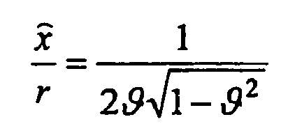
Für schwach gedämpfte Systeme mit ϑ ≤ 0,25 kann dieser Zusammenhang vereinfacht werden zu:
Der Zusammenhang zwischen dem Lehr'schen Dämpfungsmaß ϑ und der Abklingkonstanten δ im Resonanzfall mit der Eigenkreisfrequenz ω0 ergibt sich aus ϑ = ![]()
![]()
![]()
![]()
Unter Berücksichtigung der oben angegebenen Formeln kann ganz allgemein das Lehr'sche Dämpfungsmaß für ein gedämpftes Feder-Masse-System mit der Masse m und der Federrate D gemäß folgender Gleichung ermittelt werden: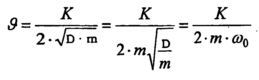
Betrachtet man nun das System des Prüfstands mit schwingender Aufstandsplatte, so ergibt sich unter Vernachlässigung der ungefederten Radmasse m2 (m2 << m1) und der Fahrzeugfeder (D3 <<< D1) für die Dämpferkonstante K des Schwingungsdämpfers folgender Zusammenhang:
Wie aus dieser Gleichung ersichtlich, kann die Dämpfungskonstante K anhand des ermittelten Amplitudenverhältnisses A, der Federkonstante D1 der Prüfstandsfeder und der Plattenmasse m1 des Prüfstands ermittelt werden.As can be seen from this equation, the damping constant K can be determined on the basis of the ascertained amplitude ratio A, the spring constant D 1 of the test bench spring and the plate mass m 1 of the test stand.
Wie bereits erwähnt, wird hierbei die Resonanzüberhöhung der erzwungenen Schwingung des Prüfstands dazu verwendet, die Dämpfung dieser Schwingung durch den Schwingungsdämpfer des Fahrzeugs bzw. dessen Dämpfungskonstante K zu ermitteln. Im Gegensatz zum Stand der Technik, bei dem das Dämpfungsmaß als Beurteilungskriterium für den Schwingungsdämpfer herangezogen wird, stellt dieses bei der vorliegenden Erfindung nur einen Zwischenschritt bzw. eine Zwischengröße dar.As already mentioned, in this case the resonance peak of the forced vibration of the test stand is used to determine the damping of this vibration by the vibration damper of the vehicle or its damping constant K. In contrast to the prior art, in which the attenuation measure is used as a criterion for the evaluation of the vibration damper, in the present invention this represents only an intermediate step or an intermediate variable.
Im nächsten Schritt wird nun das Fahrzeug ohne Prüfstand betrachtet und anhand der Fahrzeugeigenschaften das Lehr'sche Dämpfungsmaß für die Bedämpfung einer Schwingung der Fahrzeugkarosserie durch den Schwingungsdämpfer als Beurteilungsmaß ermittelt. Hierzu wird eine Schwingung des Fahrzeugaufbaus mit einer anteiligen Fahrzeugmasse m4 und der Fahrzeugfeder D3 betrachtet. Diese wird von dem Schwingungsdämpfer mit der nach dem obigen Verfahren ermittelten Dämpferkonstante K bedämpft. Für das Lehr'sche Dämpfungsmaß dieser Schwingung gilt: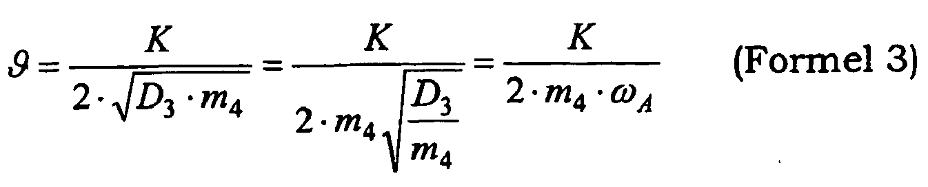
Da die Resonanzfrequenz ωA des Karosserieaufbaus zwischen verschiedenen Fahrzeugen in der Regel keine großen Unterschiede aufweist, kann hierfür ein vorgegebener bekannter Wert angenommen werden. Dieser kann z.B. für verschiedene Fahrzeugkategorien festgelegt werden. Typische Aufbauresonanzfrequenzen für PKWs sind 1,4 Hz, für Geländefahrzeuge (SUVs) 1,6 Hz und für Transporter 1,8 Hz.Since the resonance frequency ω A of the bodywork between different vehicles usually has no major differences, this a predetermined known value can be assumed. This can be specified eg for different vehicle categories. Typical superstructure resonance frequencies for cars are 1.4 Hz, for off-road vehicles (SUVs) 1.6 Hz and for transporters 1.8 Hz.
Das nach obigem Verfahren ermittelte Lehr'sche Dämpfungsmaß ϑ für das Fahrzeug stellt ein aussagekräftiges, zuverlässiges und vom Prüfstand unabhängiges Beurteilungsmaß für die Funktionsfähigkeit des Stoßdämpfers dar. Es ist deshalb möglich, einen Grenzwert festzulegen, der von Stoßdämpfern nicht unterschritten werden darf, um die Fahrsicherheit des Fahrzeugs nicht zu gefährden. Aufgrund von empirischen Untersuchungen wurde herausgefunden, dass bei funktionsfähigen Stoßdämpfern ϑ > 0,2 gilt und deshalb ein möglicher Grenzwert bei G = 0,1 liegt.The Lehr's damping factor θ for the vehicle determined by the above method represents a meaningful, reliable and independent of the test bench assessment measure for the functioning of the shock absorber. It is therefore possible to set a limit that must not be exceeded by shock absorbers to driving safety of the vehicle. Based on empirical investigations, it has been found that for functional shock absorbers θ> 0.2 and therefore a possible limit value is G = 0.1.
Die
In Schritt 100 wird die anteilige Fahrzeugmasse m4, mit welcher der zu prüfende Schwingungsdämpfer belastet wird, ermittelt. Dies kann dadurch erfolgen, dass nach dem Auffahren des Fahrzeugs auf die Aufstandsplatte die Absenkung s der Aufstandsplatte durch die Belastung mit dem Fahrzeuggewicht bei ruhendem Erregerantrieb erfasst wird. Hierzu wird der Prüfstand wie eine Waage verwendet und die anteilige Fahrzeugmasse m4 aufgrund des Federgesetztes über das entsprechende anteilige Fahrzeuggewicht F4 = m4 · g = D·s bestimmt:
Selbstverständlich kann der Schritt zur Erfassung der anteiligen Fahrzeugmasse m4 auch im Anschluss an die Erfassung der Bewegung des erregten Fahrzeugrads bzw. der Ermittlung der Dämpfungskonstante K des Schwingungsdämpfers stattfinden. In diesem Fall würde das auf der Aufstandsplatte aufstehende Fahrzeugrad zuerst zu einer erzwungenen Schwingung angeregt und anschließend würde der Wiegevorgang stattfinden.Of course, the step for detecting the proportionate vehicle mass m 4 may also take place following the detection of the movement of the excited vehicle wheel or the determination of the damping constant K of the vibration damper. In this case, the vehicle wheel resting on the footboard would first be forced to vibrate forcibly, and then the weighing operation would take place.
In Schritt 110 wird das auf der Aufstandsplatte aufstehende Rad zu einer erzwungenen Schwingung erregt. Hierzu wird die Aufstandsplatte über ein elastisches Element von einer Antriebseinheit zu vertikalen Schwingungen angeregt, wobei die Anregungsfrequenz variiert wird. Um eine Resonanz des schwingenden Systems bestehend aus Aufstandsplatte und Fahrzeugrad zu erzeugen, wird beispielsweise die Drehzahl der Antriebseinheit langsam erhöht, um die Resonanzstelle zu durchfahren. Alternativ kann die Anregung auch mit einer höheren Drehzahl beginnen, die anschließend langsam erniedrigt wird, so lange bis eine Resonanz eintritt.In
In Schritt 120 wird die Bewegung des erregten Fahrzeugrades bzw. der Aufstandsplatte erfasst. Hierzu kann beispielsweise eine Markierung am Fahrzeugrad vorgesehen sein, die von entsprechenden Sensoren erfasst wird. Einfacher ist es jedoch, Messaufnehmer an der Aufstandsplatte anzubringen und die Amplitude der vertikalen Bewegung der Aufstandsplatte zu erfassen. Da die Reifenfeder im Vergleich zur Prüfstandsfeder in der Regel eine größere Federkonstante D2 aufweist, schwingen Fahrzeugrad und Aufstandsplatte gleichphasig, ohne dass sich das Fahrzeugrad von der Aufstandsplatte löst. Es ist deshalb in der Regel ausreichend, die Bewegung der Aufstandsplatte zu erfassen bzw. die ungefederten Massen des Fahrzeugs und die Aufstandsplatte als eine schwingende Einheit zu betrachten (siehe auch das Ein-Massen-Schwingungs-System in
In Schritt 130 wird die Dämpfungskonstante K des Schwingungsdämpfers basierend auf dem in Formel 2 angegebenen Zusammenhang anhand der erfassten Bewegung des Fahrzeugrads ermittelt. Wie bereits erläutert basiert diese Berechnung auf der Auswertung des Verhältnisses zwischen der Erregungsamplitude r und der erfassten Amplitude x̂ 1 der Bewegung der Aufstandsplatte bzw. des Fahrzeugrads im Resonanzfall.In
Um die durch Reibung im Prüfstand verursachte Dämpfung der Schwingung zu berücksichtigen, wird in Schritt 140 der ermittelte Wert für die Dämpfungskonstante K korrigiert. Die kompensierte Dämpfungskonstante K' des Schwingungsdämpfers ergibt sich durch Subtraktion der aus dem Prüfvorgang ermittelten Dämpfungskonstante K um die Dämpfungskonstante KP des Prüfstands: K' = K - KP . Dieser Kompensationsschritt ist hauptsächlich bei kleineren bzw. leichteren Fahrzeugen mit kleineren Dämpfungskonstanten zweckmäßig, da für diese Fahrzeuge die Prüfstandsdämpfung bis zu 15 % der gesamten Schwingungsdämpfung betragen kann.In order to take into account the damping of the vibration caused by friction in the test stand, the determined value for the damping constant K is corrected in
Um die Verluste des Prüfstands zu bestimmen, kann ein Ausschwingversuch mit einem unbelasteten Prüfstand durchgeführt werden. Hierzu wird die Aufstandsplatte von der Antriebseinheit zu einer Schwingung angeregt, und nach dem Abschalten der Antriebseinheit wird der Amplitudenverlauf der gedämpften Schwingung erfasst. Die
Die Auswertung des Ausschwingsversuchs erfolgt vorzugsweise mit Hilfe des logarithmischen Dekrements. Hierzu werden aus dem Ausschwingversuch die Periodendauer T = 1/f und die Amplitude x̂(t) zu einem Zeitpunkt t sowie die Amplituden nach n Schwingungen x̂(t + n · T) bestimmt. Für das logarithmische Dekrement gilt: 
Aus der ermittelten Abklingkonstante δ kann so die Dämpfungskonstante KP des Prüfstands bestimmt werden: KP = 2δ·m1.From the determined decay constant δ, the damping constant K P of the test bench can be determined: K P = 2δ · m 1 .
Da die Dämpfungskonstante KP des Prüfstands in der Regel von der jeweiligen Plattenamplitude abhängig ist (siehe
In Schritt 150 wird anhand der Formel 3 das Lehr'sche Dämpfungsmaß für die Schwingung des Fahrzeugaufbaus anhand der korrigierten Dämpfungskonstante K' bestimmt. Hierzu ist es in der Regel ausreichend eine fest vorgegebene Resonanzfrequenz ωA für die Schwingung des Fahrzeugaufbaus anzunehmen. Weiterhin geht die in diesem Beispiel in Schritt 100 ermittelte anteilige Fahrzeugmasse m4 in die Berechnung ein. Das ermittelte Dämpfungsmaß ϑ kann als Beurteilungskriterium für die Resonanzüberhöhung bzw. Dämpfung der Schwingung des Fahrzeugaufbaus herangezogen werden.In
In Schritt 160 wird das ermittelte Dämpfungsmaß ϑ mit einem vorgegebenen Schwellwert G, beispielsweise 0,1, verglichen. Untersuchungen haben gezeigt, dass die Stoßdämpfer von neuwertigen Fahrzeugen sowie funktionsfähige Stoßdämpfer von älteren Fahrzeugen in der Regel diesen Grenzwert überschreiten.In
Ergibt die Prüfung in Schritt 160, dass das Lehr'sche Dämpfungsmaß des Schwingungsdämpfers den vorgegebenen Grenzwert G überschreitet, so wird der Schwingungsdämpfer in Schritt 180 als funktionsfähig erklärt.If the test in
Anderenfalls wird der geprüfte Schwingungsdämpfer in Schritt 170 zu einem defekten Schwingungsdämpfer erklärt, worauf gegebenenfalls entsprechende Maßnahmen eingeleitet werden können.Otherwise, the tested vibration damper is declared a defective vibration damper in
Im Folgenden soll anhand einer Beispielrechnung die Wirkungsweise des erfindungsgemäßen Stoßdämpferprüfstands nochmals verdeutlicht werden. Dazu werden für einen Beispielsprüfstand folgende Werte angenommen:
- Masse der Aufstandsplatte m2 = 100 kg,
- Effektive Federkonstante des Prüfstands

- Radius des Kurbeltriebs r = 10 mm.
- Mass of the uprising plate m 2 = 100 kg,
- Effective spring rate of the test bench
- Radius of the crank drive r = 10 mm.
Wird bei einer Prüfung mit einem Fahrzeug eine Resonanzamplitude x̂ 1 = 30 mm erreicht, so lässt sich aus diesen Werten die Dämpfungskonstante K des Schwingungsdämpfers ermitteln (Formel 2): 
Die anteilige Fahrzeugmasse m4 wird anhand der Absenkung der Prüfstandsplatte um s = 20 mm beim Befahren des Prüfstands mit dem Fahrzeug bestimmt (Formel 4):
Mit der so erhaltenen Dämpfungskonstante K und der anteiligen Fahrzeugmasse m4 wird unter der Annahme einer Aufbaufrequenz fA = 1,4 Hz das Lehr'sche Dämpfungsmaß ermittelt (Formel 3):
Auf diese Weise erhält man ein Beurteilungskriterium, das nicht nur den Dämpfer, sondern die gesamte Dämpfungsgüte für Schwingungen am Fahrzeug widerspiegelt.In this way, one obtains an assessment criterion that reflects not only the damper, but the overall damping quality for vibrations on the vehicle.
Das erläuterte Verfahren zum Bestimmen eines Dämpfungsmaßes für Schwingungen von Fahrzeugen ist somit zum Prüfen von eingebauten Stoßdämpfern von Kraftfahrzeugen geeignet und kann beispielsweise im Rahmen einer Fahrzeughauptuntersuchung eingesetzt werden. Der große Vorteil gegenüber bekannten Verfahren liegt darin, dass ein aussagekräftiges, zuverlässiges Beurteilungsmaß für die Funktionsfähigkeit von Stoßdämpfern ermittelt werden kann, welches unabhängig von zu prüfendem Fahrzeugtyp und den Eigenschaften des verwendeten Prüfstands ein verlässliches Beurteilungsmaß liefert.The described method for determining a damping measure for vibrations of vehicles is thus suitable for testing built-in shock absorbers of motor vehicles and can be used, for example, in the context of a vehicle main inspection. The big advantage over known methods is that a meaningful, reliable assessment of the effectiveness of shock absorbers can be determined, which provides a reliable assessment measure, regardless of the type of vehicle to be tested and the properties of the test stand used.
Die
Von dem auf dem Prüfstand aufstehenden Fahrzeug, sind schematisch ein Schwingungsdämpfer 1, ein Fahrzeugrad 2, eine Fahrzeugfeder 12, eine Radaufhängung 13 und eine Karosserie des Fahrzeugs 14 gezeigt. Gemäß dem Schwingungsmodell aus
Der Stoßdämpferprüfstand weist eine Aufstandsplatte 7, einen Rahmen 8, eine Doppelschwinge 9, eine Antriebseinheit 4 und ein erstes elastisches Element 3 auf. Die Aufstandsplatte 7 ist über die Doppelschwinge 9 und das erste elastische Element 3 mit der Antriebseinheit 4 verbunden, welche als Kurbeltrieb wirkt und die Aufstandsplatte 7 sowie das Fahrzeugrad 2 in Schwingung versetzt. Eine Steuereinheit 15 steuert die Drehzahl der Antriebseinheit 4 derart, dass das schwingende System in Resonanz gerät.The shock absorber test stand has a
Ein weiteres elastisches Element 6 (Fußpunktfeder) unterstützt die Aufstandsplatte 7 und trägt einen großen Teil des Fahrzeuggewichts (typischerweise zwischen 60 und 90 %), um ein zu starkes Absinken der Aufstandsplatte 7 bei der Belastung mit dem Fahrzeug zu vermeiden.Another elastic element 6 (Fußpunktfeder) supports the
In der Nähe der Aufstandsplatte 7 sind Erfassungsmittel 5 vorgesehen, welche die Bewegung der Aufstandsplatte 7 erfassen und ein entsprechendes Signal X an Berechnungsmittel 10, 11, Fahrzeugmassebestimmungsmittel 16 und die Steuereinheit 15 liefern. In der Steuereinheit 15 kann dieses Signal X dazu genutzt werden, um festzustellen, dass die richtige Drehzahl für eine Resonanz des schwingenden Systems erreicht ist.Detecting means 5, which detect the movement of the
Fahrzeugmassebestimmungsmittel 16 ermitteln bei abgeschalteter Erregung anhand der Absenkung s der Aufstandsplatte 7 beim Auffahren des Fahrzeugs und der effektiven Federkonstanten D die anteilige Fahrzeugmasse m4.Vehicle mass determining means 16 determine when the excitation is switched off on the basis of the reduction s of the
Die ersten Berechungsmittel 10 bestimmen anhand der Amplitude x̂ 1 der Aufstandplatte 7 im Resonanzfall (ω = ω0) und der bekannten Erregungsamplitude r die Dämpfungskostante K des Schwingungsdämpfers 1 (Formel 2), welche gegebenenfalls mit einer zuvor ermittelten Dämpfungskonstante KP des Prüfstands korrigiert werden kann.The first calculating means 10 determine on the basis of the amplitude x 1 of the
Die zweiten Berechnungsmittel 11 ermitteln anschließend das Lehr'sche Dämpfungsmaß ϑ für eine Schwingung des Fahrzeugaufbaus basierend auf der anteiligen Fahrzeugmasse m4 und der Dämpfungskonstante K des Schwingungsdämpfers 1 (Formel 3).The second calculating means 11 then determines the Lehr's damping amount θ for vibration of the vehicle body based on the proportionate vehicle mass m 4 and the damping constant K of the vibration damper 1 (Formula 3).
Anhand eines Vergleichs des ermittelten Dämpfungsmaßes ϑ mit einem vorgegebenen Grenzwert G wird von den Beurteilungsmitteln 17 die Funktionsfähigkeit des Schwingungsdämpfers 1 beurteilt und ein entsprechendes binäres Prüfsignal erzeugt, welches mit "0" anzeigt, dass der Schwingungsdämpfer 1 das Prüfkriterium nicht erfüllt, und mit "1" anzeigt, dass der Prüfschwingungsdämpfer 1 die Prüfung bestanden hat.On the basis of a comparison of the determined attenuation measure θ with a predetermined limit value G, the evaluation means 17 provide the Functionality of the
Claims (14)
- A method for determining an attenuation measure for vibrations of vehicles, comprising the steps:- exciting a vehicle wheel (2) connected to a vibration damper (1) to be judged and passing a frequency response characteristic in order to determine the test stand resonance for estimating an attenuation constant K based on the ratio between an amplitude r of the excitation and a detected amplitude x̂ of the movement of said vehicle wheel (2) and the footprint plate (7), respectively, in case of resonance, and- estimating the Lehr attenuation measure ϑ for the attenuation of a vibration of the vehicle body by means of said vibration damper (1) based on said estimated attenuation constant K of said vibration damper (1) and a proportional vehicle mass m4 acting on said vibration damper (1) and a predetermined value of said resonance frequency of the body structure, whereinsaid proportional vehicle mass m4 is determined in one of the two following ways:- based on a measurement of a lowering s of a footprint plate (7) caused by the loading by said vehicle wheel (2) or- based on the half of the permissible axle load.
- The method according to claim 1, wherein said vehicle wheel (2) stands on said periodically excited footprint plate (7), wherein a movement of said footprint plate (7) is detected, and wherein the movement of said excited vehicle wheel (2) is estimated based on said detected movement of said footprint plate (7).
- The method according to claim 1 or 2, wherein said excitement of said vehicle wheel (2) is performed via an elastic member (3), wherein another elastic member (6) is provided, and wherein said attenuation constant K is estimated considering the vibrating mass m, especially the mass m1 of said footprint plate (7), and the spring constant of said elastic members (3 and 6).
- The method according to one of the claims 1-3, wherein resonance frequencies ω A of vibrations of said vehicle structure for different vehicle categories are determined, stored and used to estimate said Lehr attenuation measure ϑ.
- The method according to one of the claims 1-4, comprising a judgement step for judging the damping characteristics of said vibration damper (1), wherein the estimated attenuation measure is compared with a limit value G.
- The method according to one of the claims 1-5, comprising a step of correcting said estimated value for said attenuation constant K considering an attenuation with which a testing apparatus attenuates vibrations of said footprint plate (7).
- The method according to one of the preceding claims, comprising a step of estimating said attenuation constant KP of said testing apparatus by detecting the amplitude values of the decreasing vibration of said unloaded footprint plate (7) after said excitation is completed, especially by means of the logarithmic decrement of detected vibration amplitudes.
- An apparatus for determining an attenuation measure for vibrations of vehicles, comprising- excitation means for exciting a vehicle wheel (2) connected to a vibration damper (1) in order to pass a frequency response characteristic for determining the test stand resonance,- detection means (5) for detecting the movement of said excited vehicle wheel (2),- first calculation means (10) for estimating an attenuation constant K of said vibration damper (1) based on the detected amplitude x̂ of the movement of the footprint plate (7) and on a movement of said excited vehicle wheel (2) and of said footprint plate (7), respectively, in case of resonance,- second calculation means (11) for estimating the Lehr attenuation measure ϑ for the attenuation of the vibration of the vehicle body by means of said vibration damper (1) based on the estimated attenuation constant K of said vibration damper (1) and on a proportional vehicle mass m4 and on a predetermined value for the resonance frequency of the body structure, whereinsaid proportional vehicle mass m4 is determined in one of the two following ways:- based on a measurement of a lowering s of a footprint plate (7) caused by the loading by said vehicle wheel (2) or- based on the half of the permissible axle load.
- The apparatus according to claim 8, comprising a footprint plate (7) on which said vehicle wheel (2) stands and a driving unit (4) which is connected to said footprint plate (7) via an elastic member (3), wherein said footprint plate (7) is periodically excitable by means of said driving unit (4).
- The apparatus according to one of the claims 8 or 9, comprising a further elastic member (6), wherein said attenuation constant K can be estimated by means of said first calculation means (10) considering the vibrating mass m, especially the mass m1 of said footprint plate (7), and the spring constant of said elastic members (3 and 6).
- The apparatus according to claim 8 to 10, comprising vehicle mass determination means (16) for determining said proportional vehicle mass m4 with which said wheel (2) is loaded by the vehicle weight.
- The apparatus according to claim 10 and 11, wherein said footprint plate (7) is supported via said further elastic member (6) and said proportional vehicle mass m4 can be estimated by means of said vehicle mass determination means (16) considering said spring constant of said elastic members (3 and 6).
- The apparatus according to one of the claims 8 to 12, comprising judging means (17) for judging the attenuation characteristics of said vibration damper (1) by comparing the estimated attenuation measure with at least one limit value G.
- The apparatus according to one of the claims 8 to 13, wherein said first calculation means (10) comprise a correcting apparatus for correcting said estimated value for said attenuation constant K of said vibration damper (1) by means of a vibration attenuation KP of said apparatus.
Priority Applications (1)
| Application Number | Priority Date | Filing Date | Title |
|---|---|---|---|
| PL05002972T PL1564538T3 (en) | 2004-02-12 | 2005-02-11 | Procedure and device for determining a measure of the vibration absorption of vehicles |
Applications Claiming Priority (2)
| Application Number | Priority Date | Filing Date | Title |
|---|---|---|---|
| DE102004006986 | 2004-02-12 | ||
| DE102004006986A DE102004006986A1 (en) | 2004-02-12 | 2004-02-12 | Method and device for determining a damping measure for vibrations of vehicles |
Publications (3)
| Publication Number | Publication Date |
|---|---|
| EP1564538A2 EP1564538A2 (en) | 2005-08-17 |
| EP1564538A3 EP1564538A3 (en) | 2006-06-07 |
| EP1564538B1 true EP1564538B1 (en) | 2010-06-09 |
Family
ID=34684028
Family Applications (1)
| Application Number | Title | Priority Date | Filing Date |
|---|---|---|---|
| EP05002972A Active EP1564538B1 (en) | 2004-02-12 | 2005-02-11 | Procedure and device for determining a measure of the vibration absorption of vehicles |
Country Status (7)
| Country | Link |
|---|---|
| EP (1) | EP1564538B1 (en) |
| AT (1) | ATE470846T1 (en) |
| DE (2) | DE102004006986A1 (en) |
| DK (1) | DK1564538T3 (en) |
| ES (1) | ES2346227T3 (en) |
| PL (1) | PL1564538T3 (en) |
| PT (1) | PT1564538E (en) |
Family Cites Families (2)
| Publication number | Priority date | Publication date | Assignee | Title |
|---|---|---|---|---|
| DE4439997C1 (en) * | 1994-11-09 | 1996-06-05 | Fichtel & Sachs Ag | Automobile shock absorber damping characteristics testing device |
| DE10143492A1 (en) * | 2001-09-05 | 2003-03-20 | Maha Gmbh & Co Kg | Method and device for testing vehicle vibration dampers and for locating body noise |
-
2004
- 2004-02-12 DE DE102004006986A patent/DE102004006986A1/en not_active Withdrawn
-
2005
- 2005-02-11 EP EP05002972A patent/EP1564538B1/en active Active
- 2005-02-11 DE DE502005009703T patent/DE502005009703D1/en active Active
- 2005-02-11 DK DK05002972.7T patent/DK1564538T3/en active
- 2005-02-11 PT PT05002972T patent/PT1564538E/en unknown
- 2005-02-11 AT AT05002972T patent/ATE470846T1/en active
- 2005-02-11 PL PL05002972T patent/PL1564538T3/en unknown
- 2005-02-11 ES ES05002972T patent/ES2346227T3/en active Active
Also Published As
| Publication number | Publication date |
|---|---|
| EP1564538A2 (en) | 2005-08-17 |
| DE102004006986A1 (en) | 2005-09-01 |
| EP1564538A3 (en) | 2006-06-07 |
| PT1564538E (en) | 2010-08-17 |
| ES2346227T3 (en) | 2010-10-13 |
| DK1564538T3 (en) | 2010-09-27 |
| PL1564538T3 (en) | 2010-11-30 |
| ATE470846T1 (en) | 2010-06-15 |
| DE502005009703D1 (en) | 2010-07-22 |
Similar Documents
| Publication | Publication Date | Title |
|---|---|---|
| EP2136195B1 (en) | Method and device for testing an installed shock absorber of a motor vehicle | |
| EP0756701B1 (en) | Process for determining the characteristics of a motor vehicle's built-in shock absorbers | |
| EP0611960B1 (en) | Method for examining a vibration damper of a vehicle | |
| EP1657471A2 (en) | Method for damping the vibrations in a suspension system and such a suspension | |
| DE3545087A1 (en) | METHOD AND DEVICE FOR CHECKING THE CHASSIS OF A MOTOR VEHICLE | |
| DE102008041745B4 (en) | Method and device for testing at least one vibration damper of a motor vehicle in the installed state | |
| DE19637432A1 (en) | Method and device for testing a shock absorber | |
| EP2159561B1 (en) | Method and device for testing a built-in vibration damper of a motor vehicle | |
| WO2011023271A1 (en) | Test stand having a vibration damper | |
| EP1291635B1 (en) | Procedure and device for testing vehicle shock absorbers | |
| EP1930711A2 (en) | Method of gathering data for authorising aircraft | |
| DE4432286A1 (en) | Device and method for testing vehicle shock absorbers | |
| DE4439997C1 (en) | Automobile shock absorber damping characteristics testing device | |
| EP1564538B1 (en) | Procedure and device for determining a measure of the vibration absorption of vehicles | |
| DE102009014749B4 (en) | Method for operating a damper in a motor vehicle | |
| EP2520921A2 (en) | Method for diagnosing a functional state of a component of an active suspension of a motor vehicle | |
| DE10337212B4 (en) | System and method for determining a loading state of a vehicle or a trailer | |
| EP1557656B1 (en) | Procedure and device for determining the suspension damping of vehicles | |
| EP1080357B1 (en) | Method and device for testing wheel suspensions | |
| DE3826196C2 (en) | ||
| EP0986743A1 (en) | Method for testing installed shock absorbers | |
| DE19823369A1 (en) | Method for testing wheel suspension of motor vehicle | |
| DE3023295A1 (en) | Functional testing of vehicle oscillation dampers - by measuring oscillation speeds and comparing with characteristics of undamped vehicle | |
| DE102011087594A1 (en) | Method for functional monitoring of vibration damper for wheel of passenger car, involves obtaining correct function and incorrect function of vibration damper, such that recognized incorrect function is provided in display | |
| DE102004024239A1 (en) | Vehicle shock absorber measurement and analysis procedure measures damped resonance and resonance curve inflection tangent frequency |
Legal Events
| Date | Code | Title | Description |
|---|---|---|---|
| PUAI | Public reference made under article 153(3) epc to a published international application that has entered the european phase |
Free format text: ORIGINAL CODE: 0009012 |
|
| AK | Designated contracting states |
Kind code of ref document: A2 Designated state(s): AT BE BG CH CY CZ DE DK EE ES FI FR GB GR HU IE IS IT LI LT LU MC NL PL PT RO SE SI SK TR |
|
| AX | Request for extension of the european patent |
Extension state: AL BA HR LV MK YU |
|
| PUAL | Search report despatched |
Free format text: ORIGINAL CODE: 0009013 |
|
| AK | Designated contracting states |
Kind code of ref document: A3 Designated state(s): AT BE BG CH CY CZ DE DK EE ES FI FR GB GR HU IE IS IT LI LT LU MC NL PL PT RO SE SI SK TR |
|
| AX | Request for extension of the european patent |
Extension state: AL BA HR LV MK YU |
|
| 17P | Request for examination filed |
Effective date: 20061207 |
|
| AKX | Designation fees paid |
Designated state(s): AT BE BG CH CY CZ DE DK EE ES FI FR GB GR HU IE IS IT LI LT LU MC NL PL PT RO SE SI SK TR |
|
| 17Q | First examination report despatched |
Effective date: 20070810 |
|
| GRAP | Despatch of communication of intention to grant a patent |
Free format text: ORIGINAL CODE: EPIDOSNIGR1 |
|
| GRAS | Grant fee paid |
Free format text: ORIGINAL CODE: EPIDOSNIGR3 |
|
| GRAA | (expected) grant |
Free format text: ORIGINAL CODE: 0009210 |
|
| AK | Designated contracting states |
Kind code of ref document: B1 Designated state(s): AT BE BG CH CY CZ DE DK EE ES FI FR GB GR HU IE IS IT LI LT LU MC NL PL PT RO SE SI SK TR |
|
| REG | Reference to a national code |
Ref country code: CH Ref legal event code: EP |
|
| REG | Reference to a national code |
Ref country code: IE Ref legal event code: FG4D Free format text: LANGUAGE OF EP DOCUMENT: GERMAN |
|
| REF | Corresponds to: |
Ref document number: 502005009703 Country of ref document: DE Date of ref document: 20100722 Kind code of ref document: P |
|
| REG | Reference to a national code |
Ref country code: PT Ref legal event code: SC4A Free format text: AVAILABILITY OF NATIONAL TRANSLATION Effective date: 20100809 |
|
| REG | Reference to a national code |
Ref country code: CH Ref legal event code: NV Representative=s name: MICHELI & CIE SA |
|
| REG | Reference to a national code |
Ref country code: NL Ref legal event code: T3 |
|
| REG | Reference to a national code |
Ref country code: GR Ref legal event code: EP Ref document number: 20100402001 Country of ref document: GR |
|
| REG | Reference to a national code |
Ref country code: DK Ref legal event code: T3 |
|
| REG | Reference to a national code |
Ref country code: ES Ref legal event code: FG2A Ref document number: 2346227 Country of ref document: ES Kind code of ref document: T3 |
|
| REG | Reference to a national code |
Ref country code: RO Ref legal event code: EPE |
|
| PG25 | Lapsed in a contracting state [announced via postgrant information from national office to epo] |
Ref country code: LT Free format text: LAPSE BECAUSE OF FAILURE TO SUBMIT A TRANSLATION OF THE DESCRIPTION OR TO PAY THE FEE WITHIN THE PRESCRIBED TIME-LIMIT Effective date: 20100609 Ref country code: SE Free format text: LAPSE BECAUSE OF FAILURE TO SUBMIT A TRANSLATION OF THE DESCRIPTION OR TO PAY THE FEE WITHIN THE PRESCRIBED TIME-LIMIT Effective date: 20100609 |
|
| LTIE | Lt: invalidation of european patent or patent extension |
Effective date: 20100609 |
|
| PG25 | Lapsed in a contracting state [announced via postgrant information from national office to epo] |
Ref country code: SI Free format text: LAPSE BECAUSE OF FAILURE TO SUBMIT A TRANSLATION OF THE DESCRIPTION OR TO PAY THE FEE WITHIN THE PRESCRIBED TIME-LIMIT Effective date: 20100609 |
|
| REG | Reference to a national code |
Ref country code: PL Ref legal event code: T3 |
|
| PG25 | Lapsed in a contracting state [announced via postgrant information from national office to epo] |
Ref country code: CY Free format text: LAPSE BECAUSE OF FAILURE TO SUBMIT A TRANSLATION OF THE DESCRIPTION OR TO PAY THE FEE WITHIN THE PRESCRIBED TIME-LIMIT Effective date: 20100609 |
|
| PG25 | Lapsed in a contracting state [announced via postgrant information from national office to epo] |
Ref country code: EE Free format text: LAPSE BECAUSE OF FAILURE TO SUBMIT A TRANSLATION OF THE DESCRIPTION OR TO PAY THE FEE WITHIN THE PRESCRIBED TIME-LIMIT Effective date: 20100609 |
|
| PG25 | Lapsed in a contracting state [announced via postgrant information from national office to epo] |
Ref country code: SK Free format text: LAPSE BECAUSE OF FAILURE TO SUBMIT A TRANSLATION OF THE DESCRIPTION OR TO PAY THE FEE WITHIN THE PRESCRIBED TIME-LIMIT Effective date: 20100609 Ref country code: IS Free format text: LAPSE BECAUSE OF FAILURE TO SUBMIT A TRANSLATION OF THE DESCRIPTION OR TO PAY THE FEE WITHIN THE PRESCRIBED TIME-LIMIT Effective date: 20101009 |
|
| PLBE | No opposition filed within time limit |
Free format text: ORIGINAL CODE: 0009261 |
|
| STAA | Information on the status of an ep patent application or granted ep patent |
Free format text: STATUS: NO OPPOSITION FILED WITHIN TIME LIMIT |
|
| PGFP | Annual fee paid to national office [announced via postgrant information from national office to epo] |
Ref country code: IE Payment date: 20110216 Year of fee payment: 7 Ref country code: DK Payment date: 20110222 Year of fee payment: 7 |
|
| 26N | No opposition filed |
Effective date: 20110310 |
|
| PGFP | Annual fee paid to national office [announced via postgrant information from national office to epo] |
Ref country code: FI Payment date: 20110217 Year of fee payment: 7 Ref country code: NL Payment date: 20110225 Year of fee payment: 7 Ref country code: CH Payment date: 20110222 Year of fee payment: 7 Ref country code: CZ Payment date: 20110203 Year of fee payment: 7 Ref country code: AT Payment date: 20110217 Year of fee payment: 7 Ref country code: PT Payment date: 20110201 Year of fee payment: 7 Ref country code: TR Payment date: 20110208 Year of fee payment: 7 Ref country code: PL Payment date: 20110201 Year of fee payment: 7 Ref country code: RO Payment date: 20110207 Year of fee payment: 7 |
|
| PGRI | Patent reinstated in contracting state [announced from national office to epo] |
Ref country code: IT Effective date: 20110501 |
|
| PGFP | Annual fee paid to national office [announced via postgrant information from national office to epo] |
Ref country code: GR Payment date: 20110225 Year of fee payment: 7 |
|
| REG | Reference to a national code |
Ref country code: DE Ref legal event code: R097 Ref document number: 502005009703 Country of ref document: DE Effective date: 20110309 |
|
| PGFP | Annual fee paid to national office [announced via postgrant information from national office to epo] |
Ref country code: GB Payment date: 20110221 Year of fee payment: 7 Ref country code: BE Payment date: 20110221 Year of fee payment: 7 |
|
| PG25 | Lapsed in a contracting state [announced via postgrant information from national office to epo] |
Ref country code: MC Free format text: LAPSE BECAUSE OF NON-PAYMENT OF DUE FEES Effective date: 20110228 |
|
| REG | Reference to a national code |
Ref country code: PT Ref legal event code: MM4A Free format text: LAPSE DUE TO NON-PAYMENT OF FEES Effective date: 20120813 |
|
| BERE | Be: lapsed |
Owner name: MAHA MASCHINENBAU HALDENWANG G.M.B.H. & CO. KG Effective date: 20120228 |
|
| REG | Reference to a national code |
Ref country code: NL Ref legal event code: V1 Effective date: 20120901 |
|
| REG | Reference to a national code |
Ref country code: CH Ref legal event code: PL |
|
| GBPC | Gb: european patent ceased through non-payment of renewal fee |
Effective date: 20120211 |
|
| REG | Reference to a national code |
Ref country code: GR Ref legal event code: ML Ref document number: 20100402001 Country of ref document: GR Effective date: 20120905 |
|
| PG25 | Lapsed in a contracting state [announced via postgrant information from national office to epo] |
Ref country code: FI Free format text: LAPSE BECAUSE OF NON-PAYMENT OF DUE FEES Effective date: 20120211 Ref country code: CZ Free format text: LAPSE BECAUSE OF NON-PAYMENT OF DUE FEES Effective date: 20120211 Ref country code: CH Free format text: LAPSE BECAUSE OF NON-PAYMENT OF DUE FEES Effective date: 20120229 Ref country code: LI Free format text: LAPSE BECAUSE OF NON-PAYMENT OF DUE FEES Effective date: 20120229 |
|
| REG | Reference to a national code |
Ref country code: DK Ref legal event code: EBP |
|
| REG | Reference to a national code |
Ref country code: IE Ref legal event code: MM4A |
|
| PG25 | Lapsed in a contracting state [announced via postgrant information from national office to epo] |
Ref country code: GR Free format text: LAPSE BECAUSE OF NON-PAYMENT OF DUE FEES Effective date: 20120905 Ref country code: PT Free format text: LAPSE BECAUSE OF NON-PAYMENT OF DUE FEES Effective date: 20120813 |
|
| REG | Reference to a national code |
Ref country code: AT Ref legal event code: MM01 Ref document number: 470846 Country of ref document: AT Kind code of ref document: T Effective date: 20120211 |
|
| PG25 | Lapsed in a contracting state [announced via postgrant information from national office to epo] |
Ref country code: BE Free format text: LAPSE BECAUSE OF NON-PAYMENT OF DUE FEES Effective date: 20120228 |
|
| PG25 | Lapsed in a contracting state [announced via postgrant information from national office to epo] |
Ref country code: AT Free format text: LAPSE BECAUSE OF NON-PAYMENT OF DUE FEES Effective date: 20120211 Ref country code: GB Free format text: LAPSE BECAUSE OF NON-PAYMENT OF DUE FEES Effective date: 20120211 Ref country code: NL Free format text: LAPSE BECAUSE OF NON-PAYMENT OF DUE FEES Effective date: 20120901 Ref country code: IE Free format text: LAPSE BECAUSE OF NON-PAYMENT OF DUE FEES Effective date: 20120211 |
|
| PG25 | Lapsed in a contracting state [announced via postgrant information from national office to epo] |
Ref country code: RO Free format text: LAPSE BECAUSE OF NON-PAYMENT OF DUE FEES Effective date: 20120211 |
|
| PG25 | Lapsed in a contracting state [announced via postgrant information from national office to epo] |
Ref country code: LU Free format text: LAPSE BECAUSE OF NON-PAYMENT OF DUE FEES Effective date: 20110211 Ref country code: PL Free format text: LAPSE BECAUSE OF NON-PAYMENT OF DUE FEES Effective date: 20120211 |
|
| REG | Reference to a national code |
Ref country code: PL Ref legal event code: LAPE |
|
| PG25 | Lapsed in a contracting state [announced via postgrant information from national office to epo] |
Ref country code: BG Free format text: LAPSE BECAUSE OF FAILURE TO SUBMIT A TRANSLATION OF THE DESCRIPTION OR TO PAY THE FEE WITHIN THE PRESCRIBED TIME-LIMIT Effective date: 20100909 |
|
| PG25 | Lapsed in a contracting state [announced via postgrant information from national office to epo] |
Ref country code: DK Free format text: LAPSE BECAUSE OF NON-PAYMENT OF DUE FEES Effective date: 20120229 Ref country code: HU Free format text: LAPSE BECAUSE OF FAILURE TO SUBMIT A TRANSLATION OF THE DESCRIPTION OR TO PAY THE FEE WITHIN THE PRESCRIBED TIME-LIMIT Effective date: 20100609 |
|
| PG25 | Lapsed in a contracting state [announced via postgrant information from national office to epo] |
Ref country code: TR Free format text: LAPSE BECAUSE OF NON-PAYMENT OF DUE FEES Effective date: 20120211 |
|
| REG | Reference to a national code |
Ref country code: FR Ref legal event code: PLFP Year of fee payment: 12 |
|
| REG | Reference to a national code |
Ref country code: FR Ref legal event code: PLFP Year of fee payment: 13 |
|
| REG | Reference to a national code |
Ref country code: FR Ref legal event code: PLFP Year of fee payment: 14 |
|
| PGFP | Annual fee paid to national office [announced via postgrant information from national office to epo] |
Ref country code: FR Payment date: 20230220 Year of fee payment: 19 Ref country code: ES Payment date: 20230317 Year of fee payment: 19 |
|
| PGFP | Annual fee paid to national office [announced via postgrant information from national office to epo] |
Ref country code: IT Payment date: 20230228 Year of fee payment: 19 Ref country code: DE Payment date: 20230228 Year of fee payment: 19 |