EP1564505A1 - Air conditioner - Google Patents
Air conditioner Download PDFInfo
- Publication number
- EP1564505A1 EP1564505A1 EP03772833A EP03772833A EP1564505A1 EP 1564505 A1 EP1564505 A1 EP 1564505A1 EP 03772833 A EP03772833 A EP 03772833A EP 03772833 A EP03772833 A EP 03772833A EP 1564505 A1 EP1564505 A1 EP 1564505A1
- Authority
- EP
- European Patent Office
- Prior art keywords
- refrigerant
- heat source
- line
- units
- liquid
- Prior art date
- Legal status (The legal status is an assumption and is not a legal conclusion. Google has not performed a legal analysis and makes no representation as to the accuracy of the status listed.)
- Withdrawn
Links
Images





Classifications
-
- F—MECHANICAL ENGINEERING; LIGHTING; HEATING; WEAPONS; BLASTING
- F25—REFRIGERATION OR COOLING; COMBINED HEATING AND REFRIGERATION SYSTEMS; HEAT PUMP SYSTEMS; MANUFACTURE OR STORAGE OF ICE; LIQUEFACTION SOLIDIFICATION OF GASES
- F25B—REFRIGERATION MACHINES, PLANTS OR SYSTEMS; COMBINED HEATING AND REFRIGERATION SYSTEMS; HEAT PUMP SYSTEMS
- F25B13/00—Compression machines, plants or systems, with reversible cycle
-
- F—MECHANICAL ENGINEERING; LIGHTING; HEATING; WEAPONS; BLASTING
- F25—REFRIGERATION OR COOLING; COMBINED HEATING AND REFRIGERATION SYSTEMS; HEAT PUMP SYSTEMS; MANUFACTURE OR STORAGE OF ICE; LIQUEFACTION SOLIDIFICATION OF GASES
- F25B—REFRIGERATION MACHINES, PLANTS OR SYSTEMS; COMBINED HEATING AND REFRIGERATION SYSTEMS; HEAT PUMP SYSTEMS
- F25B41/00—Fluid-circulation arrangements
-
- F—MECHANICAL ENGINEERING; LIGHTING; HEATING; WEAPONS; BLASTING
- F25—REFRIGERATION OR COOLING; COMBINED HEATING AND REFRIGERATION SYSTEMS; HEAT PUMP SYSTEMS; MANUFACTURE OR STORAGE OF ICE; LIQUEFACTION SOLIDIFICATION OF GASES
- F25B—REFRIGERATION MACHINES, PLANTS OR SYSTEMS; COMBINED HEATING AND REFRIGERATION SYSTEMS; HEAT PUMP SYSTEMS
- F25B2313/00—Compression machines, plants or systems with reversible cycle not otherwise provided for
- F25B2313/006—Compression machines, plants or systems with reversible cycle not otherwise provided for two pipes connecting the outdoor side to the indoor side with multiple indoor units
-
- F—MECHANICAL ENGINEERING; LIGHTING; HEATING; WEAPONS; BLASTING
- F25—REFRIGERATION OR COOLING; COMBINED HEATING AND REFRIGERATION SYSTEMS; HEAT PUMP SYSTEMS; MANUFACTURE OR STORAGE OF ICE; LIQUEFACTION SOLIDIFICATION OF GASES
- F25B—REFRIGERATION MACHINES, PLANTS OR SYSTEMS; COMBINED HEATING AND REFRIGERATION SYSTEMS; HEAT PUMP SYSTEMS
- F25B2313/00—Compression machines, plants or systems with reversible cycle not otherwise provided for
- F25B2313/023—Compression machines, plants or systems with reversible cycle not otherwise provided for using multiple indoor units
- F25B2313/0233—Compression machines, plants or systems with reversible cycle not otherwise provided for using multiple indoor units in parallel arrangements
-
- F—MECHANICAL ENGINEERING; LIGHTING; HEATING; WEAPONS; BLASTING
- F25—REFRIGERATION OR COOLING; COMBINED HEATING AND REFRIGERATION SYSTEMS; HEAT PUMP SYSTEMS; MANUFACTURE OR STORAGE OF ICE; LIQUEFACTION SOLIDIFICATION OF GASES
- F25B—REFRIGERATION MACHINES, PLANTS OR SYSTEMS; COMBINED HEATING AND REFRIGERATION SYSTEMS; HEAT PUMP SYSTEMS
- F25B2313/00—Compression machines, plants or systems with reversible cycle not otherwise provided for
- F25B2313/023—Compression machines, plants or systems with reversible cycle not otherwise provided for using multiple indoor units
- F25B2313/0233—Compression machines, plants or systems with reversible cycle not otherwise provided for using multiple indoor units in parallel arrangements
- F25B2313/02331—Compression machines, plants or systems with reversible cycle not otherwise provided for using multiple indoor units in parallel arrangements during cooling
-
- F—MECHANICAL ENGINEERING; LIGHTING; HEATING; WEAPONS; BLASTING
- F25—REFRIGERATION OR COOLING; COMBINED HEATING AND REFRIGERATION SYSTEMS; HEAT PUMP SYSTEMS; MANUFACTURE OR STORAGE OF ICE; LIQUEFACTION SOLIDIFICATION OF GASES
- F25B—REFRIGERATION MACHINES, PLANTS OR SYSTEMS; COMBINED HEATING AND REFRIGERATION SYSTEMS; HEAT PUMP SYSTEMS
- F25B2313/00—Compression machines, plants or systems with reversible cycle not otherwise provided for
- F25B2313/023—Compression machines, plants or systems with reversible cycle not otherwise provided for using multiple indoor units
- F25B2313/0234—Compression machines, plants or systems with reversible cycle not otherwise provided for using multiple indoor units in series arrangements
- F25B2313/02344—Compression machines, plants or systems with reversible cycle not otherwise provided for using multiple indoor units in series arrangements during heating
-
- F—MECHANICAL ENGINEERING; LIGHTING; HEATING; WEAPONS; BLASTING
- F25—REFRIGERATION OR COOLING; COMBINED HEATING AND REFRIGERATION SYSTEMS; HEAT PUMP SYSTEMS; MANUFACTURE OR STORAGE OF ICE; LIQUEFACTION SOLIDIFICATION OF GASES
- F25B—REFRIGERATION MACHINES, PLANTS OR SYSTEMS; COMBINED HEATING AND REFRIGERATION SYSTEMS; HEAT PUMP SYSTEMS
- F25B2313/00—Compression machines, plants or systems with reversible cycle not otherwise provided for
- F25B2313/025—Compression machines, plants or systems with reversible cycle not otherwise provided for using multiple outdoor units
- F25B2313/0253—Compression machines, plants or systems with reversible cycle not otherwise provided for using multiple outdoor units in parallel arrangements
-
- F—MECHANICAL ENGINEERING; LIGHTING; HEATING; WEAPONS; BLASTING
- F25—REFRIGERATION OR COOLING; COMBINED HEATING AND REFRIGERATION SYSTEMS; HEAT PUMP SYSTEMS; MANUFACTURE OR STORAGE OF ICE; LIQUEFACTION SOLIDIFICATION OF GASES
- F25B—REFRIGERATION MACHINES, PLANTS OR SYSTEMS; COMBINED HEATING AND REFRIGERATION SYSTEMS; HEAT PUMP SYSTEMS
- F25B2313/00—Compression machines, plants or systems with reversible cycle not otherwise provided for
- F25B2313/031—Sensor arrangements
- F25B2313/0314—Temperature sensors near the indoor heat exchanger
-
- F—MECHANICAL ENGINEERING; LIGHTING; HEATING; WEAPONS; BLASTING
- F25—REFRIGERATION OR COOLING; COMBINED HEATING AND REFRIGERATION SYSTEMS; HEAT PUMP SYSTEMS; MANUFACTURE OR STORAGE OF ICE; LIQUEFACTION SOLIDIFICATION OF GASES
- F25B—REFRIGERATION MACHINES, PLANTS OR SYSTEMS; COMBINED HEATING AND REFRIGERATION SYSTEMS; HEAT PUMP SYSTEMS
- F25B2313/00—Compression machines, plants or systems with reversible cycle not otherwise provided for
- F25B2313/031—Sensor arrangements
- F25B2313/0315—Temperature sensors near the outdoor heat exchanger
-
- F—MECHANICAL ENGINEERING; LIGHTING; HEATING; WEAPONS; BLASTING
- F25—REFRIGERATION OR COOLING; COMBINED HEATING AND REFRIGERATION SYSTEMS; HEAT PUMP SYSTEMS; MANUFACTURE OR STORAGE OF ICE; LIQUEFACTION SOLIDIFICATION OF GASES
- F25B—REFRIGERATION MACHINES, PLANTS OR SYSTEMS; COMBINED HEATING AND REFRIGERATION SYSTEMS; HEAT PUMP SYSTEMS
- F25B2400/00—Component parts or details not otherwise provided for in this subclass
- F25B2400/06—Several compression cycles arranged in parallel
-
- F—MECHANICAL ENGINEERING; LIGHTING; HEATING; WEAPONS; BLASTING
- F25—REFRIGERATION OR COOLING; COMBINED HEATING AND REFRIGERATION SYSTEMS; HEAT PUMP SYSTEMS; MANUFACTURE OR STORAGE OF ICE; LIQUEFACTION SOLIDIFICATION OF GASES
- F25B—REFRIGERATION MACHINES, PLANTS OR SYSTEMS; COMBINED HEATING AND REFRIGERATION SYSTEMS; HEAT PUMP SYSTEMS
- F25B2400/00—Component parts or details not otherwise provided for in this subclass
- F25B2400/07—Details of compressors or related parts
- F25B2400/075—Details of compressors or related parts with parallel compressors
-
- F—MECHANICAL ENGINEERING; LIGHTING; HEATING; WEAPONS; BLASTING
- F25—REFRIGERATION OR COOLING; COMBINED HEATING AND REFRIGERATION SYSTEMS; HEAT PUMP SYSTEMS; MANUFACTURE OR STORAGE OF ICE; LIQUEFACTION SOLIDIFICATION OF GASES
- F25B—REFRIGERATION MACHINES, PLANTS OR SYSTEMS; COMBINED HEATING AND REFRIGERATION SYSTEMS; HEAT PUMP SYSTEMS
- F25B2400/00—Component parts or details not otherwise provided for in this subclass
- F25B2400/16—Receivers
- F25B2400/161—Receivers arranged in parallel
-
- F—MECHANICAL ENGINEERING; LIGHTING; HEATING; WEAPONS; BLASTING
- F25—REFRIGERATION OR COOLING; COMBINED HEATING AND REFRIGERATION SYSTEMS; HEAT PUMP SYSTEMS; MANUFACTURE OR STORAGE OF ICE; LIQUEFACTION SOLIDIFICATION OF GASES
- F25B—REFRIGERATION MACHINES, PLANTS OR SYSTEMS; COMBINED HEATING AND REFRIGERATION SYSTEMS; HEAT PUMP SYSTEMS
- F25B2400/00—Component parts or details not otherwise provided for in this subclass
- F25B2400/19—Pumping down refrigerant from one part of the cycle to another part of the cycle, e.g. when the cycle is changed from cooling to heating, or before a defrost cycle is started
-
- F—MECHANICAL ENGINEERING; LIGHTING; HEATING; WEAPONS; BLASTING
- F25—REFRIGERATION OR COOLING; COMBINED HEATING AND REFRIGERATION SYSTEMS; HEAT PUMP SYSTEMS; MANUFACTURE OR STORAGE OF ICE; LIQUEFACTION SOLIDIFICATION OF GASES
- F25B—REFRIGERATION MACHINES, PLANTS OR SYSTEMS; COMBINED HEATING AND REFRIGERATION SYSTEMS; HEAT PUMP SYSTEMS
- F25B2500/00—Problems to be solved
- F25B2500/16—Lubrication
-
- F—MECHANICAL ENGINEERING; LIGHTING; HEATING; WEAPONS; BLASTING
- F25—REFRIGERATION OR COOLING; COMBINED HEATING AND REFRIGERATION SYSTEMS; HEAT PUMP SYSTEMS; MANUFACTURE OR STORAGE OF ICE; LIQUEFACTION SOLIDIFICATION OF GASES
- F25B—REFRIGERATION MACHINES, PLANTS OR SYSTEMS; COMBINED HEATING AND REFRIGERATION SYSTEMS; HEAT PUMP SYSTEMS
- F25B2500/00—Problems to be solved
- F25B2500/27—Problems to be solved characterised by the stop of the refrigeration cycle
-
- F—MECHANICAL ENGINEERING; LIGHTING; HEATING; WEAPONS; BLASTING
- F25—REFRIGERATION OR COOLING; COMBINED HEATING AND REFRIGERATION SYSTEMS; HEAT PUMP SYSTEMS; MANUFACTURE OR STORAGE OF ICE; LIQUEFACTION SOLIDIFICATION OF GASES
- F25B—REFRIGERATION MACHINES, PLANTS OR SYSTEMS; COMBINED HEATING AND REFRIGERATION SYSTEMS; HEAT PUMP SYSTEMS
- F25B2700/00—Sensing or detecting of parameters; Sensors therefor
- F25B2700/19—Pressures
- F25B2700/193—Pressures of the compressor
- F25B2700/1931—Discharge pressures
-
- F—MECHANICAL ENGINEERING; LIGHTING; HEATING; WEAPONS; BLASTING
- F25—REFRIGERATION OR COOLING; COMBINED HEATING AND REFRIGERATION SYSTEMS; HEAT PUMP SYSTEMS; MANUFACTURE OR STORAGE OF ICE; LIQUEFACTION SOLIDIFICATION OF GASES
- F25B—REFRIGERATION MACHINES, PLANTS OR SYSTEMS; COMBINED HEATING AND REFRIGERATION SYSTEMS; HEAT PUMP SYSTEMS
- F25B2700/00—Sensing or detecting of parameters; Sensors therefor
- F25B2700/19—Pressures
- F25B2700/193—Pressures of the compressor
- F25B2700/1933—Suction pressures
-
- F—MECHANICAL ENGINEERING; LIGHTING; HEATING; WEAPONS; BLASTING
- F25—REFRIGERATION OR COOLING; COMBINED HEATING AND REFRIGERATION SYSTEMS; HEAT PUMP SYSTEMS; MANUFACTURE OR STORAGE OF ICE; LIQUEFACTION SOLIDIFICATION OF GASES
- F25B—REFRIGERATION MACHINES, PLANTS OR SYSTEMS; COMBINED HEATING AND REFRIGERATION SYSTEMS; HEAT PUMP SYSTEMS
- F25B2700/00—Sensing or detecting of parameters; Sensors therefor
- F25B2700/21—Temperatures
- F25B2700/2104—Temperatures of an indoor room or compartment
-
- F—MECHANICAL ENGINEERING; LIGHTING; HEATING; WEAPONS; BLASTING
- F25—REFRIGERATION OR COOLING; COMBINED HEATING AND REFRIGERATION SYSTEMS; HEAT PUMP SYSTEMS; MANUFACTURE OR STORAGE OF ICE; LIQUEFACTION SOLIDIFICATION OF GASES
- F25B—REFRIGERATION MACHINES, PLANTS OR SYSTEMS; COMBINED HEATING AND REFRIGERATION SYSTEMS; HEAT PUMP SYSTEMS
- F25B2700/00—Sensing or detecting of parameters; Sensors therefor
- F25B2700/21—Temperatures
- F25B2700/2106—Temperatures of fresh outdoor air
-
- F—MECHANICAL ENGINEERING; LIGHTING; HEATING; WEAPONS; BLASTING
- F25—REFRIGERATION OR COOLING; COMBINED HEATING AND REFRIGERATION SYSTEMS; HEAT PUMP SYSTEMS; MANUFACTURE OR STORAGE OF ICE; LIQUEFACTION SOLIDIFICATION OF GASES
- F25B—REFRIGERATION MACHINES, PLANTS OR SYSTEMS; COMBINED HEATING AND REFRIGERATION SYSTEMS; HEAT PUMP SYSTEMS
- F25B2700/00—Sensing or detecting of parameters; Sensors therefor
- F25B2700/21—Temperatures
- F25B2700/2115—Temperatures of a compressor or the drive means therefor
- F25B2700/21151—Temperatures of a compressor or the drive means therefor at the suction side of the compressor
-
- F—MECHANICAL ENGINEERING; LIGHTING; HEATING; WEAPONS; BLASTING
- F25—REFRIGERATION OR COOLING; COMBINED HEATING AND REFRIGERATION SYSTEMS; HEAT PUMP SYSTEMS; MANUFACTURE OR STORAGE OF ICE; LIQUEFACTION SOLIDIFICATION OF GASES
- F25B—REFRIGERATION MACHINES, PLANTS OR SYSTEMS; COMBINED HEATING AND REFRIGERATION SYSTEMS; HEAT PUMP SYSTEMS
- F25B2700/00—Sensing or detecting of parameters; Sensors therefor
- F25B2700/21—Temperatures
- F25B2700/2115—Temperatures of a compressor or the drive means therefor
- F25B2700/21152—Temperatures of a compressor or the drive means therefor at the discharge side of the compressor
-
- F—MECHANICAL ENGINEERING; LIGHTING; HEATING; WEAPONS; BLASTING
- F25—REFRIGERATION OR COOLING; COMBINED HEATING AND REFRIGERATION SYSTEMS; HEAT PUMP SYSTEMS; MANUFACTURE OR STORAGE OF ICE; LIQUEFACTION SOLIDIFICATION OF GASES
- F25B—REFRIGERATION MACHINES, PLANTS OR SYSTEMS; COMBINED HEATING AND REFRIGERATION SYSTEMS; HEAT PUMP SYSTEMS
- F25B31/00—Compressor arrangements
- F25B31/002—Lubrication
- F25B31/004—Lubrication oil recirculating arrangements
Definitions
- the present invention relates to an air conditioner, and more particularly to an air conditioner having a plurality of heat source units.
- heat source side branch liquid lines and heat source side branch gas lines of the plurality of heat source units are connected to a separately provided line unit, and the heat source side branch liquid lines and the heat source side branch gas lines are merged together inside the line unit as a refrigerant liquid junction line and a refrigerant gas junction line and connected to user units.
- This line unit not only functions to integrate the aforementioned heat source side branch liquid lines and the heat source side branch gas lines into a refrigerant liquid junction line and a refrigerant gas junction line, but when some of the plurality of heat source units stop operating in response to the operational burden of the user units, the line unit also functions to accumulate refrigerant inside the stopped heat source units to prevent a shortage in the refrigerant that flows between the user units and the operating heat source units.
- the heat source side branch liquid lines and the heat source side branch gas lines of each heat source unit can be merged together into a refrigerant liquid junction line and a refrigerant gas junction line by simply connecting the heat source side branch liquid lines and the heat source side branch gas lines to the line unit, and thus the ability to construct the air conditioner at the location in which it is to be installed can be improved (see, for example, Japanese Published Unexamined Patent Application No. H06-249527).
- An object of the present invention is to eliminate the line unit in an air conditioner that includes a plurality of heat source units, and hold increases in onsite line construction to a minimum while making it possible to adjust the amount of refrigerant in the air conditioner.
- An air conditioner disclosed in claim 1 includes a plurality of heat source units, a refrigerant liquid junction line and a refrigerant gas junction line, user units, and a refrigerant supply circuit.
- the heat source units each include a compression mechanism and a heat source side heat exchanger.
- the refrigerant liquid junction line and the refrigerant gas junction line parallel connect each heat source unit.
- the user units each include a user side heat exchanger, and are connected to the refrigerant liquid junction line and the refrigerant gas junction line.
- the refrigerant supply circuit is used in situations in which some of the heat source units have stopped operating in response to the operational burden of the user units, and includes a refrigerant removal line provided in each heat source unit that serves to remove to the exterior of the stopped heat source units the refrigerant that accumulates in the interior of the heat source units, and a communication line that connects the refrigerant removal lines and the intake side of the compression mechanisms of the operating heat source units.
- equipment control is performed in which, for example, some of the plurality of the heat source units are stopped in response to the operational burden of the user units.
- refrigerant gas discharged from the compression mechanisms in the operating heat source units is condensed by the heat source side heat exchangers into refrigerant liquid and merged into the refrigerant liquid junction line, the refrigerant liquid is evaporated into refrigerant gas by the user side heat exchangers of the user units, and the refrigerant gas is drawn into the compression mechanisms of the operating heat source units via the refrigerant gas junction line.
- refrigerant gas discharged from the compression mechanisms is merged together in the refrigerant gas junction line, the refrigerant gas is condensed by the user side heat exchangers of the user units into refrigerant liquid, the refrigerant liquid is sent to the operating heat source units via the refrigerant liquid junction line, the refrigerant liquid is evaporated into refrigerant gas by the heat source side heat exchangers, and the refrigerant gas is drawn into the compression mechanisms of the operating heat source units.
- the refrigerant supply circuit is employed to supply refrigerant accumulated inside the stopped heat source units to the intake sides of the compression mechanisms of the operating heat source units, so that there will be no shortage of refrigerant flowing between the user units and the operating heat source units.
- the refrigerant supply circuit includes the refrigerant removal lines that remove to the exterior of the heat source units refrigerant that accumulates in the interior of the heat source units, and a communication line that connects the refrigerant removal lines and the intake sides of the compression mechanisms of the operating heat source units.
- a function that adjusts the quantity of refrigerant so that there are no shortages thereof is achieved in this air conditioner by simply providing essential components that form the refrigerant supply circuit in the interior of the heat source units, and providing a communication line between the heat source units. This allows the line unit provided in the prior art to be eliminated, and allows increases in onsite line construction to be held to a minimum while preventing refrigerant shortages.
- the air conditioner disclosed in claim 2 is the air conditioner of claim 1, in which the heat source side heat exchangers are connected to the discharge sides of the compression mechanisms.
- Each heat source unit further includes a heat source side branch liquid line that is connected to the liquid side of the heat source side heat exchanger and the refrigerant liquid junction line, a receiver that is provided on the heat source side branch liquid line, and a heat source side branch gas line that is connected to the intake side of the compression mechanism and the refrigerant gas junction line.
- Each refrigerant removal line is arranged such that it removes refrigerant from between the discharge side of the compression mechanism and the gas side of the heat source side heat exchanger.
- each heat source side branch liquid line includes a refrigerant open/close mechanism that closes so that refrigerant will not flow from the refrigerant liquid junction line to the interior of a stopped heat source unit when refrigerant accumulated inside the stopped heat source unit is to be removed to the exterior thereof via the refrigerant removal line.
- refrigerant accumulated in a stopped heat source unit can be removed to the exterior of the heat source unit with good efficiency by means of the refrigerant open/close mechanism, because the refrigerant open/close mechanism can be closed so that refrigerant will not flow from the refrigerant line junction line to the interior of the stopped heat source unit.
- the air conditioner disclosed in claim 4 is the air conditioner in claim 3, in which the refrigerant open/close mechanism can make refrigerant liquid that flows in the refrigerant liquid junction line flow into the interior of a stopped heat source unit when the quantity of refrigerant that flows between the user units and the operating heat source units reaches an excessive state.
- the quantity of refrigerant in the operating heat source units can be reduced by operating the refrigerant open/close mechanism to make refrigerant that flows in the refrigerant liquid junction line flow into a stopped heat source unit and accumulate in the receiver thereof. This allows the quantity of refrigerant in the air conditioner to be adjusted.
- the air conditioner disclosed in claim 5 is the air conditioner of claim 1, in which the heat source side heat exchangers are connected to the intake sides of the compressor mechanisms.
- Each heat source unit further includes a heat source side branch liquid line that is connected to the liquid side of the heat source side heat exchanger and the refrigerant liquid junction line, a heat source side branch gas line that is connected to the discharge side of the compression mechanism and the refrigerant gas junction line, and a receiver that is provided on the heat source side branch liquid line.
- the refrigerant removal line is arranged such that it removes refrigerant from between the intake side of the compression mechanism and the gas side of the heat source side heat exchanger.
- the refrigerant removal line is provided between the intake side of the compression mechanism and the gas side of the heat source side heat exchanger, the portion of the accumulated refrigerant inside a stopped heat source unit that exists from the intake side of the compression mechanism to the heat source side branch liquid line (including the receiver) will be supplied to the operating heat source units via the refrigerant removal line.
- the refrigerant liquid accumulated inside the receiver is evaporated by the heat source side heat exchanger, and then supplied to the operating heat source units via the refrigerant removal line.
- each heat source side branch liquid line includes a refrigerant open/close mechanism that closes so that refrigerant will not flow from the refrigerant liquid junction line to the interior of a stopped heat source unit when refrigerant accumulated inside the stopped heat source units is to be removed to the exterior of the heat source units via the refrigerant removal line.
- the refrigerant open/close mechanism can be closed so that refrigerant will not flow from the refrigerant liquid junction line to the interior of a stopped heat source unit, refrigerant accumulated in the stopped heat source unit can be removed to the exterior of the heat source unit with good efficiency by means of the refrigerant open/close mechanism.
- the air conditioner disclosed in claim 7 is the air conditioner disclosed in claim 6, in which a stopped heat source unit further includes a receiver pressurization circuit that makes some of the refrigerant that flows in the refrigerant gas junction line flow into the receiver via the heat source side branch gas line.
- the refrigerant liquid accumulated in the receiver can be discharged to the heat source side branch liquid line with the refrigerant open/close mechanism in the closed state because the receiver can be pressurized by means of the receiver pressurization circuit.
- the air conditioner disclosed in claim 8 is the air conditioner in claim 6 or 7, in which the refrigerant open/close mechanism can make refrigerant liquid that flows in the refrigerant liquid junction line to flow into the interior of a stopped heat source unit when the quantity of refrigerant that flows between the user units and the operating heat source units reaches an excessive state.
- the quantity of refrigerant that flows between the user units and the operating heat source units reaches an excessive state
- the quantity of refrigerant that flows between the user units and the operating heat source units can be reduced by operating a refrigerant open/close mechanism to make refrigerant that flows in the refrigerant liquid junction line flow into a stopped heat source unit and accumulate in the receiver thereof. This allows the quantity of refrigerant in the air conditioner to be adjusted.
- the air conditioner disclosed in claim 9 is the air conditioner disclosed in any of claims 1 to 8, in which the communication line is an oil equalization line that equally distributes oil between the compression mechanisms of each heat source unit.
- junction line also serves as an oil equalization line.
- the air conditioner disclosed in claim 10 includes a plurality of heat source units, a refrigerant liquid junction line and a refrigerant gas junction line, user units, and receiver depressurization circuits.
- Each heat source unit includes a compression mechanism, a heat source side heat exchanger that is connected to the intake side of the compression mechanism, and a receiver that is connected to the liquid side of the heat source side heat exchanger.
- the refrigerant liquid junction line and the refrigerant gas junction line parallel connect each heat source unit.
- Each user unit includes a user side heat exchanger, and is connected to the refrigerant liquid junction line and the refrigerant gas junction line.
- the receiver depressurization circuits make refrigerant flow out from the receivers of the heat source units that have a shortage of refrigerant to the intake sides of the compression mechanisms.
- refrigerant gas discharged from the compressor mechanisms is merged together in the refrigerant gas junction line, the refrigerant gas is condensed by the user side heat exchangers of the user units into refrigerant liquid, the refrigerant liquid is sent to the operating heat source units via the refrigerant liquid junction line, the refrigerant liquid is evaporated into refrigerant gas by the heat source side heat exchangers, and the refrigerant gas is drawn into the compressor mechanisms of the operating heat source units.
- refrigerant liquid will be unequally distributed to each heat source unit in situations in which all of the heat source units are operating and the refrigerant that flows in the refrigerant liquid junction line is in the gas-liquid phase. In this type of situation, the quantity of refrigerant liquid to be supplied to certain heat source units will be reduced, and a refrigerant shortage will be created.
- heat source unit includes the receiver depressurization circuits
- the quantity of refrigerant that will flow from the refrigerant liquid junction line into the heat source units in which there is a refrigerant shortage can be increased by making refrigerant flow from the receivers of the heat source units in which there is a shortage of refrigerant to the intake sides of the compressor mechanisms thereof.
- This allows refrigerant shortages to be eliminated, and allows the quantity of refrigerant to be sent from the refrigerant liquid junction line to each heat source unit to be maintained at an appropriate flow rate balance.
- This allows the line unit provided in the prior art to be eliminated, and allows increases in onsite line construction to be held to a minimum while preventing refrigerant shortages.
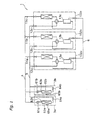
- FIG. 1 is a block diagram showing the configuration of an air conditioner according to an embodiment of the present invention.
- An air conditioner 1 includes first, second, and third heat source units 102a - 102c (three units in the present embodiment), a refrigerant liquid junction line 4 and a refrigerant gas junction line 5 that serve to serially connect the heat source units 102a - 102c, and a plurality of user units 3a, 3b (2 units in this embodiment) that are parallel connected to the refrigerant liquid junction line 4 and the refrigerant gas junction line 5.
- heat source side branch liquid lines 11a - 11c of the heat source units 102a -102c are respectively connected to the refrigerant liquid junction line 4, and the heat source side branch gas lines 12a - 12c of the heat source units 102a -102c are respectively connected to the refrigerant gas junction line 5.
- the heat source units 102a - 102c include compression mechanisms 13a - 13c that include one or more compressors.
- An oil equalization line 6 is provided between these compression mechanisms 13a - 13c, and allows oil to be exchanged between the heat source units 102a - 102c.
- This air conditioner can increase or decrease the number of heat source units 102a -102c in operation in response to the operational burden of the user units 3a, 3b.
- the user units 3a, 3b will be described. Note that because the configurations of the user unit 3a and the user unit 3b are the same, only details regarding the user unit 3a will be disclosed, and a description of the user unit 3b will be omitted.
- the user unit 3a primarily includes a user side expansion valve 61a, a user side heat exchanger 62a, and a line that that connects these.
- the user side expansion valve 61a is an electric expansion valve that is connected to the liquid side of the user side heat exchanger 62a, and serves to adjust the refrigerant flow rate and the like.
- the user side heat exchanger 62a is a cross fin tube type of heat exchanger, and serves to exchange heat with indoor air.
- the user unit 3a takes in indoor air into the interior thereof, includes an indoor fan for blowing (not shown in the figures), and is capable of exchanging heat between the indoor air and the refrigerant that flows in the user side heat exchanger 62a.
- a liquid side temperature sensor 63a that detects the refrigerant liquid temperature is arranged on the liquid side of the user side heat exchanger 62a
- a gas side temperature sensor 64a that detects the refrigerant gas temperature is arranged on the gas side of the user side heat exchanger 62a.
- a room temperature sensor 65a that detects the temperature of indoor air is provided in the user unit 3 a.
- Fig. 2 shows an outline of a refrigerant circuit of the first heat source unit 102a. Note that in the description below, only the details of the first heat source unit 102a will be disclosed, and a description of the second and third heat source units 102b, 102c will be omitted because the first heat source unit 102a has the same configuration as the second and third heat source units 102b, 102c.
- the heat source unit 102a primarily includes a compression mechanism 13a, a four way switching valve 14a, a heat source side heat exchanger 15a, a bridge circuit 16a, a receiver 17a, a liquid side gate valve 18a, a gas side gate valve 19a, an oil removal line 20a, a refrigerant removal line 21a, a receiver pressurization circuit 22a, a receiver depressurization circuit 23a, and a line that connects these.
- the compression mechanism 13a primarily includes a compressor 31a, an oil separator (not shown in the figures), and a check valve 32a that is provided on the discharge side of the compressor 31a.
- the compressor 31a is an electric motor driven scroll type compressor, and serves to compress refrigerant gas that has been drawn therein.
- the four way switching valve 14a serves to switch the direction of the refrigerant flow.
- the four way switching valve 14a connects the discharge side of the compression mechanism 13a and the gas side of the heat source side heat exchanger 15a, and connects the intake side of the compression mechanism 13a and the heat source side branch gas line 12a (refer to the solid line of the four way switching valve 14a in Fig. 2).
- the four way switching valve 14a connects the discharge side of the compression mechanism 13a and the heat source side branch liquid line 11a, and connects the intake side of the compression mechanism 13a and the gas side of the heat source side heat exchanger 15a (refer to the broken line of the four way switching valve 14a in Fig. 2).
- the heat source side heat exchanger 15a is a cross fin tube type of heat exchanger, and serves to exchange heat between air and refrigerant that acts as a heat source.
- the heat source unit 102a takes in outdoor air into the interior thereof, includes an outdoor fan for blowing (not shown in the figures), and is capable of exchanging heat between the outdoor air and the refrigerant that flows in the heat source side heat exchanger 15a.
- the receiver 17a is a vessel that serves to temporarily accumulate refrigerant that flows between the heat source side heat exchanger 15a and the user side heat exchangers 62a, 62b of the user units 3a, 3b.
- the receiver 17a includes an intake port on the upper portion of the vessel, and a discharge port on the lower portion of the vessel.
- the intake port and the discharge port of the receiver 17a are respectively connected to the heat source side branch liquid line 11 a via the bridge circuit 16a.
- the bridge circuit 16a includes three check valves 33a - 35a that are connected to the heat source side branch liquid line 11a, a heat source side expansion valve 36a, and a first open/close mechanism 37a.
- the bridge circuit 16a functions to make refrigerant flow from the intake port side of the receiver 17a into the receiver 17a, as well as return refrigerant liquid from the discharge port of the receiver 17a to the heat source side branch liquid line 11a, either when refrigerant that flows in the refrigerant circuit between the heat source side heat exchanger 15a and the user side heat exchangers 62a, 62b flows from the heat source side heat exchanger 15a to the receiver 17a, or when refrigerant that flows in the refrigerant circuit between the heat source side heat exchanger 15a and the user side heat exchangers 62a, 62b flows from the user side heat exchangers 62a, 62b to the receiver 17a.
- the check valve 33a is connected such that refrigerant that flows in the direction from the user side heat exchangers 62a, 62b to the heat source side heat exchanger 15a is guided to the intake port of the receiver 17a.
- the check valve 34a is connected such that refrigerant that flows in the direction from the heat source side heat exchangers 15a to the user side heat exchangers 62a, 62b is guided to the intake port of the receiver 17a.
- the check valve 35a is connected such that refrigerant can flow from the discharge port of the receiver 17a to the user side heat exchangers 62a, 62b.
- the heat source side expansion valve 36a is connected such that refrigerant can flow from the discharge port of the receiver 17a to the heat source side heat exchanger 15a.
- the heat source side expansion valve 36a is an electric expansion valve that serves to adjust the refrigerant flow rate between the heat source side heat exchanger 15a and the user side heat exchangers 62a, 62b.
- the first open/close mechanism 37a is arranged so that it can allow or prevent the refrigerant to flow from the liquid side gate valve 18a toward the receiver 17a.
- the first open/close mechanism 37a is a solenoid valve that is arranged on the liquid side gate valve 18a side of the check valve 33a.
- the refrigerant that flows from the heat source side branch liquid line 11a into the receiver 17a will always flow therein from the intake port of the receiver 17a, and the refrigerant from the discharge port of the receiver 17a will always be returned to the heat source side branch liquid line 11a.
- the oil removal line 20a is an oil line that serves to exchange oil between the compression mechanism 13a and the second heat source unit 102b and the third heat source unit 102c, and includes an oil discharge line 38a that discharges oil to the exterior of the compressor 31a when the quantity of oil in an oil accumulation portion of the compressor 31a exceeds a predetermined quantity, and an oil return line 39a that is branched from the oil discharge line 38a and which can return oil to the intake side of the compression mechanism 13a.
- the oil discharge line 38a is formed from a check valve 40a, a capillary 41a, an oil gate valve 42a, and an oil line that connects these.
- the oil return line 39a is formed from an oil return valve 43a that is a solenoid valve, a check valve 44a, and an oil line that connects these. Then, an oil equalization circuit that serves to exchange the oil of the compression mechanisms of each heat source unit 102a - 102c is formed by the oil removal line 20a and the oil equalization line 6 that serves to connect the compression mechanisms of the heat source units 102a - 102c.
- the refrigerant removal line 21 a is a refrigerant line that is arranged such that refrigerant from between the four way switching valve 14a and the heat source side heat exchanger 15a can be removed to the exterior of the heat source unit, and includes a second open/close mechanism 45a that is a solenoid valve, a check valve 46a, and a refrigerant line that connects these.
- the refrigerant removal line 21 a is connected to the oil removal line 20a, and refrigerant is removed to the exterior of the heat source unit via the oil equalization line 6 that serves to connect the compression mechanisms of each heat source unit 102a - 102c.
- a refrigerant supply circuit that serves to exchange refrigerant between each heat source unit 102a - 102c is formed by the refrigerant removal line 21a, the oil removal line 20a, and the oil equalization line 6.
- the receiver pressurization circuit 22a is a refrigerant line that is arranged such that refrigerant from between the discharge side of the compression mechanism 13a and the four way switching valve 14a can be sent directly to the intake port of the receiver 17a, and includes a third open/closed mechanism 47a that is a solenoid valve, a check valve 48a, a capillary 49a, and a refrigerant line that connects these.
- the receiver depressurization circuit 23a is a refrigerant line that is arranged such that refrigerant from the upper portion of the receiver 17a can flow to the intake side of the compression mechanism 13a, and includes a fourth open/close valve 50a that is a solenoid valve, and a refrigerant line that connects these.
- various sensors are provided in the heat source unit 102a.
- a discharge temperature sensor 51 a that detects the discharge refrigerant temperature of the compression mechanism 13a and a discharge pressure sensor 52a are provided on the discharge side of the compression mechanism 13a.
- An intake temperature sensor 53a that detects the intake refrigerant temperature of the compression mechanism 13a and an intake pressure sensor 54a are provided on the intake side of the compression mechanism 13a.
- a heat exchange temperature sensor 55a that detects refrigerant temperature is provided on the liquid side of the heat source side heat exchanger 15a.
- An outside air temperature sensor 56a that detects the temperature of the outside air is provided near the heat source side heat exchanger 15a.
- the apertures of the user side expansion valves 61 a, 61 b and the heat source side expansion valve 36a heat source side expansion valves 36b, 36c in the case of the heat source units 102b, 102c
- the capacity of the compression mechanism 13a the compression mechanisms 13b, 13c in the case of the heat source units 102b, 102c
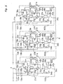
- Fig. 3 is an outline of the refrigeration circuits of the heat source units 102a - 102c when all of the heat source units 102a - 102c are performing cooling operations (the arrows in the figure show the direction of the refrigerant and oil flows).
- Figs. 4 and 5 are outlines of the refrigeration circuits of the heat source units 102a - 102c when the heat source units 102a, 102c are performing cooling operations and the heat source unit 102b is stopped (the arrows in the figure show the direction of the refrigerant and oil flows).
- Fig. 3 is an outline of the refrigeration circuits of the heat source units 102a - 102c when all of the heat source units 102a - 102c are performing cooling operations (the arrows in the figure show the direction of the refrigerant and oil flows).
- Fig. 4 and 5 are outlines of the refrigeration circuits of the heat source units 102a - 102c when the heat source units 102a, 102c are performing cooling operations
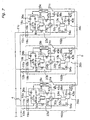
- FIG. 6 is an outline of the refrigeration circuits of the heat source units 102a - 102c when all of the heat source units 102a - 102c are performing heating operations (the arrows in the figure show the direction of the refrigerant and oil flows).
- Figs. 7 and 8 are outlines of the refrigeration circuits of the heat source units 102a - 102c when the heat source units 102a, 102c are performing heating operations and the heat source unit 102b is stopped (the arrows in the figure show the direction of the refrigerant and oil flows).
- the four way switching valves 14a - 14c of each heat source unit 102a - 102c are in the state illustrated by the solid lines in Fig. 3, i.e., the state in which the discharge sides of the compression mechanisms 13a - 13c are respectively connected to the gas sides of the heat source side heat exchangers 15a -15c, and the intake sides of the compression mechanisms 13a - 13c are respectively connected to the heat source side branch gas lines 12a - 12c.
- the liquid side gate valves 18a - 18c, the gas side gate valve 19a - 19c, the oil gate valves 42a - 42c, and the first open/close mechanisms 37a - 37c of each heat source unit are open.
- the oil return line 39a is placed into a state in which it can be used, and the refrigerant removal line 21a, the receiver pressurization circuit 22a, and the receiver depressurization circuit 23a are placed into a state in which they will not be used.
- the oil return valves 43a - 43c are completely open, and the second open/close mechanisms 45a - 45c, the third open/close mechanisms 47a - 47c, and the fourth open/close mechanisms 50a - 50c are closed.
- the apertures of the user side expansion valves 61a, 61b of the user units 3a, 3b shown in Fig. 1 are adjusted so that the refrigerant pressure is reduced.
- the heat source side expansion valve 36a - 36c are in the closed state.
- each heat source unit refrigeration circuit With the heat source unit refrigeration circuits in this state, the compression mechanisms 13a - 13c of each heat source units 102a - 102c begin operating. When this occurs, the high pressure refrigerant gas discharged from each compression mechanism 13a - 13c is condensed by each heat source side heat exchanger 15a - 15c and becomes refrigerant liquid, and this refrigerant liquid is merged into the refrigerant liquid junction line 4 via the bridge circuits 16a - 16c (more specifically the check valves 34a - 34c), the receivers 17a -17c, the bridge circuits 16a - 16c (more specifically the check valves 35a - 35c), and the heat source side branch liquid lines 11a - 11c.
- the bridge circuits 16a - 16c more specifically the check valves 34a - 34c
- the receivers 17a -17c the bridge circuits 16a - 16c (more specifically the check valves 35a - 35c)
- the pressure of the refrigerant liquid is reduced by the user side expansion valves 61a, 61b of the user unit 3a, 3b, and then the refrigerant liquid is evaporated by the user side heat exchangers 62a, 62b and becomes a low pressure refrigerant gas.
- This refrigerant gas is branched from the refrigerant gas junction line 5 to each heat source side branch gas line 12a - 12c, returns to the compressor mechanisms 13a - 13c of each heat source unit 102a - 102c, and then repeats this circulation operation.
- each oil discharged from the oil accumulation portion of each compression mechanism 13a - 13c to each oil discharge line 38a - 38c is returned to the intake side of the compression mechanisms 13a - 13c by each oil return line 39a - 39c, and is drawn into each compression mechanism 13a - 13c together with the low pressure refrigerant.
- the compression mechanism 13b of the heat source unit 102b is stopped, and the first open/close mechanism 37b and oil return valve 43b are closed.
- the refrigerant pressure from the discharge side of the compression mechanism 13b of the heat source unit 102b to the heat source side branch liquid line 11b will be reduced.
- the first open/close mechanism 37b is closed, refrigerant liquid will not flow from the refrigerant liquid junction line 4 into the heat source unit 102b.
- the oil discharged from the accumulation portion of the compressor 31a of the compression mechanism 13b to the oil discharge line 38b passes through the oil equalization line 6 and the oil return lines 39a, 39c, and is sent to the intake side of the compression mechanisms 13a, 13c of the heat source units 102a, 102c.
- refrigerant will be accumulated inside the stopped heat source unit 102b, and the quantity of refrigerant that circulates between the user units 3a, 3b and the operating heat source units 102a, 102c will be reduced (a refrigerant shortage state).
- a refrigerant shortage state can be determined from the refrigerant temperature detected by the temperature sensors 63a, 64a, 63b, 64b of the user units 3a, 3b and the apertures of the user side expansion valves 61a, 61b. Then, as shown in Fig.
- the refrigerant accumulated between the receiver 17b and the check valve 32b arranged on the discharge side of the compressor 31b of the heat source unit 102b passes through the refrigerant removal line 21a and the oil equalization line 6 and is supplied to the operating heat source units 102a, 102c by opening the second open/close mechanism 45b of the stopped heat source unit 102b for only a predetermined time period.
- the refrigerant liquid accumulated in the receiver 17a of the heat source unit 102b is evaporated by the heat source side heat exchanger 15b, and then supplied to the intake side of the compression mechanisms 13a, 13c.
- this refrigerant gas passes through the oil return lines 39a, 39c of the heat source units 102a, 102c and is supplied to the intake side of the compression mechanisms 13a, 13c.
- the second open/close mechanism 45b will be closed after the expiration of the predetermined time period, but if it is determined after closing the second open/close mechanism 45b that the refrigerant shortage state has not been eliminated and that the refrigerant shortage state still exists, the second open/close mechanism 45b will be opened again for only the predetermined time period. In this way, the quantity of refrigerant that circulates between the user units 3a, 3b and the user heat source units 102a, 102c will be increased and the refrigerant shortage state will be eliminated.
- the refrigerant accumulated inside the heat source unit 102b will be supplied in excess to the operating heat source units 102a, 102c and an excessive refrigerant state will be created.
- the second open/close mechanism 45b of the stopped heat source unit 102b will be closed, and refrigerant will not be discharged from the interior of the heat source unit 102b.
- the refrigerant liquid will be made to flow into the receiver 17b from the refrigerant liquid junction line 4 via the heat source side branch line 11b by opening the first open/close mechanism 37b, and the excessive refrigerant state will be eliminated.
- the first open/close mechanism 37b is opened for only a predetermined time period and then closed, and will be re-opened for only the predetermined period of time if there is an excessive refrigerant state.
- an appropriate refrigerant circulation quantity can be maintained by opening and closing the first and second open/close mechanisms 37b, 45b of the stopped heat source unit 102b.
- the four way switching valves 14a - 14c of each heat source unit 102a - 102c are in the state illustrated by the broken lines in Fig. 6, i.e., the state in which the discharge sides of the compression mechanisms 13a - 13c are respectively connected to the heat source side branch gas lines 12a - 12c, and the intake sides of the compression mechanisms 13a - 13c are respectively connected to the gas sides of the heat source side heat exchangers 15a - 15c.
- the liquid side gate valves 18a - 18c, the gas side gate valve 19a - 19c, the oil gate valves 42a - 42c, and the first open/close mechanisms 37a - 37c of each heat source unit are open.
- the oil return line 39a is placed into a state in which it can be used, and the refrigerant removal line 21a, the receiver pressurization circuit 22a, and the receiver depressurization circuit 23a are placed into a state in which they will not be used.
- the oil return valves 43a - 43c are completely open, and the second open/close mechanisms 45a - 45c, the third open/close mechanisms 47a - 47c, and the fourth open/close mechanisms 50a - 50c are closed.
- the apertures of the user side expansion valves 61a, 61b of the user unit 3a, 3b are adjusted in response to the heating burden of the user units 3a, 3b.
- the apertures of the heat source side expansion valves 36a - 36c are respectively adjusted based upon the degree of refrigerant gas superheating calculated from the refrigerant temperature and pressure detected by the temperature sensor 53a and the pressure sensor 54a.
- each heat source unit refrigeration circuits With the heat source unit refrigeration circuits in this state, the compression mechanisms 13a - 13c of each heat source units 102a - 102c begin operating. When this occurs, high pressure refrigerant gas discharged from each compression mechanism 13a - 13c is merged into the refrigerant gas junction line 5 via each heat source side branch gas line 12a - 12c. After that, the refrigerant gas is condensed by the user side heat exchangers 62a, 62b of the user units 3a, 3b and becomes refrigerant liquid, and the pressure of the refrigerant liquid is reduced by the user side expansion valves 61a, 61 b.
- This refrigerant liquid is branched from the refrigerant liquid junction line 4 to each heat source side branch liquid line 11a - 11c, flows through the bridge circuits 16a - 16c (more specifically the first open/close mechanisms 37a - 37c and the check valves 33a - 33c), the receivers 17a - 17c, and the bridge circuits 16a -16c (more specifically the check valves 36a - 36c), is evaporated by the heat source side heat exchangers 15a - 15c of each heat source side unit 102a - 102c, then returns to the compressor mechanisms 13a - 13c, and then repeats this circulation operation.
- each compression mechanism 13a - 13c the oil discharged from the oil accumulation portion of each compression mechanism 13a - 13c to each oil discharge line 38a - 38c passes through the oil return lines 39a- 39c, is returned to the intake side of the compression mechanisms 13a - 13c, and is drawn into each compression mechanism 13a - 13c together with the low pressure refrigerant gas.
- the air conditioner 1 of the present embodiment can operate to eliminate unequal flow when this state is created.
- the operation of the heat source unit 102b when the quantity of refrigerant sent from the refrigerant liquid junction line 4 to the heat source unit 102b is less than that sent to the other heat source units 102a, 102c will be described below.
- the aperture of the heat source side expansion valve 36b is adjusted based upon the degree of refrigerant gas superheating calculated from the refrigerant temperature and pressure detected by the temperature sensor 53b and the pressure sensor 54b. Because of this, the quantity of refrigerant supplied inside the unit will be reduced, the degree of refrigerant gas superheating will increase, and the aperture of the heat source side expansion valve 36b will increase. However, even if the heat source side expansion valve 36b is completely open, if the degree of refrigerant gas superheating increases, it will be determined that the quantity of refrigerant supplied inside the unit is insufficient, and the fourth open/close mechanism 50b will open for only a predetermined time period.
- the refrigerant inside the receiver 17b will be discharged to the intake side of the compression mechanism 13b via the receiver depressurization circuit 23b, and the pressure inside the receiver 17b will be reduced. In this way, the quantity of refrigerant supplied from the refrigerant liquid junction line 4 to the heat source unit 102b will increase. Then, if the time period that the fourth open/close mechanism 50b equals the predetermined time period, the degree of refrigerant gas superheating has been reduced, or the heat source side expansion valve 36b has begun to close, the fourth open/close mechanism 50b will close. By operating the fourth open/close mechanism 50b in this way, a refrigerant shortage in the heat source unit 102b will be eliminated. Even with the other heat source units 102a, 102c, the quantity of refrigerant sent from the refrigerant liquid junction line 4 to each heat source unit will be maintained at an appropriate flow rate balance.
- the compression mechanism 13b of the heat source unit 102 is stopped, and the first open/close mechanism 37b and oil return valve 43b are closed. At this point, because the first open/close mechanism 37b is closed, refrigerant liquid will not flow from the refrigerant liquid junction line 4 into the heat source unit 102b.
- the oil discharged from the accumulation portion of the compressor 31 a of the compression mechanism 13b to the oil discharge line 38b passes through the oil equalization line 6, and is sent to the intake side of the compression mechanisms 13a, 13c of the heat source units 102a, 102c.
- refrigerant will accumulate inside the stopped heat source unit 102b, and the quantity of refrigerant that circulates in the refrigerant circuit will be reduced (a refrigerant shortage state).
- a refrigerant shortage state can be determined from the refrigerant temperature detected by the temperature sensors 63a, 64a, 63b, 64b of the user units 3a, 3b and the apertures of the user side expansion valves 61a, 61b. Then, if it is determined that a refrigerant shortage state exists, the refrigerant accumulated in the stopped heat source unit 102b will be supplied to the operating heat source units 102a, 102c.
- the speed with which refrigerant liquid accumulates in the receiver 17b may increase immediately after the heat source units conducting heating operations are stopped. If this occurs, like during cooling operations, a sufficient refrigerant discharge speed may not be obtained by simply opening the second open/close mechanism 45b. Because of this, as shown in Fig. 7, high pressure refrigerant gas from the refrigerant gas junction line 5 will be supplied to the receiver 17b via the heat source side branch gas line 12b, the four way switching valve 14b, and the receiver pressurization circuit 22b by opening the third open/close mechanism 47b.
- the refrigerant liquid inside the receiver 17b will be discharged to the exterior of the heat source unit via the heat source side branch liquid line 11b because the receiver 17b is pressurized and the pressure thereof is higher than the pressure of the refrigerant liquid junction line 4.
- the refrigerant shortage state will be eliminated.
- the refrigerant accumulated inside the heat source unit 102b may be supplied in excess to the operating heat source units 102a, 102c and thus an excessive refrigerant state will be created.
- the third open/close mechanism 47b of the stopped heat source unit 102b will be closed, and refrigerant will not be discharged from the interior of the heat source unit 102b.
- the refrigerant liquid will be made to flow into the receiver 17b from the refrigerant liquid junction line 4 via the heat source side branch line 11b by opening the first open/close mechanism 37b, and the excessive refrigerant state will be eliminated.
- an appropriate refrigerant circulation quantity can be maintained by opening and closing the first and third open/close mechanisms 37b, 47b of the stopped heat source unit 102b.
- the line unit in an air conditioner that incl udes a plurality of heat source units can be eliminated, and increases in the onsite line construction can be held to a minimum while making it possible to adjust the amount of refrigerant in the air conditioner.
Landscapes
- Engineering & Computer Science (AREA)
- Physics & Mathematics (AREA)
- Mechanical Engineering (AREA)
- Thermal Sciences (AREA)
- General Engineering & Computer Science (AREA)
- Compression-Type Refrigeration Machines With Reversible Cycles (AREA)
- Air Conditioning Control Device (AREA)
Abstract
The present invention is capable of eliminating the line unit in an air conditioner
that includes a plurality of heat source units, and hold increases in onsite line construction
to a minimum while making it possible to adjust the amount of refrigerant in the air
conditioner. The air conditioner (1) includes a plurality of heat source units (102a - 102c),
a refrigerant liquid junction line (4) and a refrigerant gas junction line (5), user units (3a,
3b), and a refrigerant supply circuit. The refrigerant supply circuit is used in situations in
which some of the plurality of heat source units (102a - 120c) stop operating in response to
the operational burden of the user units (3a, 3b), and is formed from refrigerant removal
lines (21a - 21 c) that remove refrigerant that accumulates inside stopped heat source units
to the exterior thereof, and an oil equalization line (6) and oil removal lines (20a - 20c)
that connect the refrigerant removal lines (21 a - 21 c) of each stopped heat source unit and
the intake sides of the compression mechanisms (13a - 13c) of the operating heat source
units.
Description
The present invention relates to an air conditioner, and more particularly to
an air conditioner having a plurality of heat source units.
In some conventional air conditioners having a plurality of heat source units, heat
source side branch liquid lines and heat source side branch gas lines of the plurality of heat
source units are connected to a separately provided line unit, and the heat source side
branch liquid lines and the heat source side branch gas lines are merged together inside the
line unit as a refrigerant liquid junction line and a refrigerant gas junction line and
connected to user units.
This line unit not only functions to integrate the aforementioned heat source side
branch liquid lines and the heat source side branch gas lines into a refrigerant liquid
junction line and a refrigerant gas junction line, but when some of the plurality of heat
source units stop operating in response to the operational burden of the user units, the line
unit also functions to accumulate refrigerant inside the stopped heat source units to prevent
a shortage in the refrigerant that flows between the user units and the operating heat source
units.
With this type of air conditioner, the heat source side branch liquid lines and the
heat source side branch gas lines of each heat source unit can be merged together into a
refrigerant liquid junction line and a refrigerant gas junction line by simply connecting the
heat source side branch liquid lines and the heat source side branch gas lines to the line
unit, and thus the ability to construct the air conditioner at the location in which it is to be
installed can be improved (see, for example, Japanese Published Unexamined Patent
Application No. H06-249527).
However, from a manufacturing viewpoint, the line unit of the aforemention
ed conventional air conditioner must be manufactured and stored as inventory, and t
hus causes costs to increase. Thus, there is a need to eliminate the line unit when
seen from the perspective of manufacturing these units.
An object of the present invention is to eliminate the line unit in an air conditioner
that includes a plurality of heat source units, and hold increases in onsite line construction
to a minimum while making it possible to adjust the amount of refrigerant in the air
conditioner.
An air conditioner disclosed in claim 1 includes a plurality of heat source units, a
refrigerant liquid junction line and a refrigerant gas junction line, user units, and a
refrigerant supply circuit. The heat source units each include a compression mechanism
and a heat source side heat exchanger. The refrigerant liquid junction line and the
refrigerant gas junction line parallel connect each heat source unit. The user units each
include a user side heat exchanger, and are connected to the refrigerant liquid junction line
and the refrigerant gas junction line. The refrigerant supply circuit is used in situations in
which some of the heat source units have stopped operating in response to the operational
burden of the user units, and includes a refrigerant removal line provided in each heat
source unit that serves to remove to the exterior of the stopped heat source units the
refrigerant that accumulates in the interior of the heat source units, and a communication
line that connects the refrigerant removal lines and the intake side of the compression
mechanisms of the operating heat source units.
In this air conditioner, equipment control is performed in which, for example,
some of the plurality of the heat source units are stopped in response to the operational
burden of the user units. Thus, during cooling operations, refrigerant gas discharged from
the compression mechanisms in the operating heat source units is condensed by the heat
source side heat exchangers into refrigerant liquid and merged into the refrigerant liquid
junction line, the refrigerant liquid is evaporated into refrigerant gas by the user side heat
exchangers of the user units, and the refrigerant gas is drawn into the compression
mechanisms of the operating heat source units via the refrigerant gas junction line. In
addition, during heating operations, refrigerant gas discharged from the compression
mechanisms is merged together in the refrigerant gas junction line, the refrigerant gas is
condensed by the user side heat exchangers of the user units into refrigerant liquid, the
refrigerant liquid is sent to the operating heat source units via the refrigerant liquid junction
line, the refrigerant liquid is evaporated into refrigerant gas by the heat source side heat
exchangers, and the refrigerant gas is drawn into the compression mechanisms of the
operating heat source units. On the other hand, the refrigerant supply circuit is employed to
supply refrigerant accumulated inside the stopped heat source units to the intake sides of
the compression mechanisms of the operating heat source units, so that there will be no
shortage of refrigerant flowing between the user units and the operating heat source units.
Here, the refrigerant supply circuit includes the refrigerant removal lines that
remove to the exterior of the heat source units refrigerant that accumulates in the interior of
the heat source units, and a communication line that connects the refrigerant removal lines
and the intake sides of the compression mechanisms of the operating heat source units. In
other words, a function that adjusts the quantity of refrigerant so that there are no shortages
thereof is achieved in this air conditioner by simply providing essential components that
form the refrigerant supply circuit in the interior of the heat source units, and providing a
communication line between the heat source units. This allows the line unit provided in the
prior art to be eliminated, and allows increases in onsite line construction to be held to a
minimum while preventing refrigerant shortages.
The air conditioner disclosed in claim 2 is the air conditioner of claim 1, in which
the heat source side heat exchangers are connected to the discharge sides of the
compression mechanisms. Each heat source unit further includes a heat source side branch
liquid line that is connected to the liquid side of the heat source side heat exchanger and
the refrigerant liquid junction line, a receiver that is provided on the heat source side
branch liquid line, and a heat source side branch gas line that is connected to the intake
side of the compression mechanism and the refrigerant gas junction line. Each refrigerant
removal line is arranged such that it removes refrigerant from between the discharge side
of the compression mechanism and the gas side of the heat source side heat exchanger.
During cooling operations with this air conditioner, because a refrigerant removal
line is provided between the discharge sides of each compression mechanism and the gas
sides of each heat source side heat exchanger, the portion of the accumulated refrigerant
inside each stopped heat source unit that exists from the discharge side of the compression
mechanism to the heat source side branch liquid line (including the receiver) will be
supplied to the operating heat source units via the refrigerant removal line. At this point,
the refrigerant liquid accumulated inside the receiver is evaporated by the heat source side
heat exchanger, and then supplied to the operating heat source units via the refrigerant
removal line.
The air conditioner disclosed in claim 3 is the air conditioner of claim 2, in which
each heat source side branch liquid line includes a refrigerant open/close mechanism that
closes so that refrigerant will not flow from the refrigerant liquid junction line to the
interior of a stopped heat source unit when refrigerant accumulated inside the stopped heat
source unit is to be removed to the exterior thereof via the refrigerant removal line.
In this air conditioner, refrigerant accumulated in a stopped heat source unit can
be removed to the exterior of the heat source unit with good efficiency by means of the
refrigerant open/close mechanism, because the refrigerant open/close mechanism can be
closed so that refrigerant will not flow from the refrigerant line junction line to the interior
of the stopped heat source unit.
The air conditioner disclosed in claim 4 is the air conditioner in claim 3, in which
the refrigerant open/close mechanism can make refrigerant liquid that flows in the
refrigerant liquid junction line flow into the interior of a stopped heat source unit when the
quantity of refrigerant that flows between the user units and the operating heat source units
reaches an excessive state.
In this air conditioner, when the quantity of refrigerant that flows between the user
units and the operating heat source units reaches an excessive state, the quantity of
refrigerant in the operating heat source units can be reduced by operating the refrigerant
open/close mechanism to make refrigerant that flows in the refrigerant liquid junction line
flow into a stopped heat source unit and accumulate in the receiver thereof. This allows the
quantity of refrigerant in the air conditioner to be adjusted.
The air conditioner disclosed in claim 5 is the air conditioner of claim 1, in which
the heat source side heat exchangers are connected to the intake sides of the compressor
mechanisms. Each heat source unit further includes a heat source side branch liquid line
that is connected to the liquid side of the heat source side heat exchanger and the
refrigerant liquid junction line, a heat source side branch gas line that is connected to the
discharge side of the compression mechanism and the refrigerant gas junction line, and a
receiver that is provided on the heat source side branch liquid line. The refrigerant removal
line is arranged such that it removes refrigerant from between the intake side of the
compression mechanism and the gas side of the heat source side heat exchanger.
During heating operations with this air conditioner, because the refrigerant
removal line is provided between the intake side of the compression mechanism and the
gas side of the heat source side heat exchanger, the portion of the accumulated refrigerant
inside a stopped heat source unit that exists from the intake side of the compression
mechanism to the heat source side branch liquid line (including the receiver) will be
supplied to the operating heat source units via the refrigerant removal line. At this point,
the refrigerant liquid accumulated inside the receiver is evaporated by the heat source side
heat exchanger, and then supplied to the operating heat source units via the refrigerant
removal line.
The air conditioner disclosed in claim 6 is the air conditioner of claim 5, in which
each heat source side branch liquid line includes a refrigerant open/close mechanism that
closes so that refrigerant will not flow from the refrigerant liquid junction line to the
interior of a stopped heat source unit when refrigerant accumulated inside the stopped heat
source units is to be removed to the exterior of the heat source units via the refrigerant
removal line.
In this air conditioner, because the refrigerant open/close mechanism can be
closed so that refrigerant will not flow from the refrigerant liquid junction line to the
interior of a stopped heat source unit, refrigerant accumulated in the stopped heat source
unit can be removed to the exterior of the heat source unit with good efficiency by means
of the refrigerant open/close mechanism.
The air conditioner disclosed in claim 7 is the air conditioner disclosed in claim 6,
in which a stopped heat source unit further includes a receiver pressurization circuit that
makes some of the refrigerant that flows in the refrigerant gas junction line flow into the
receiver via the heat source side branch gas line.
In this air conditioner, the refrigerant liquid accumulated in the receiver can be
discharged to the heat source side branch liquid line with the refrigerant open/close
mechanism in the closed state because the receiver can be pressurized by means of the
receiver pressurization circuit.
The air conditioner disclosed in claim 8 is the air conditioner in claim 6 or 7, in
which the refrigerant open/close mechanism can make refrigerant liquid that flows in the
refrigerant liquid junction line to flow into the interior of a stopped heat source unit when
the quantity of refrigerant that flows between the user units and the operating heat source
units reaches an excessive state.
In this air conditioner, when the quantity of refrigerant that flows between the user
units and the operating heat source units reaches an excessive state, the quantity of
refrigerant that flows between the user units and the operating heat source units can be
reduced by operating a refrigerant open/close mechanism to make refrigerant that flows in
the refrigerant liquid junction line flow into a stopped heat source unit and accumulate in
the receiver thereof. This allows the quantity of refrigerant in the air conditioner to be
adjusted.
The air conditioner disclosed in claim 9 is the air conditioner disclosed in any of
claims 1 to 8, in which the communication line is an oil equalization line that equally
distributes oil between the compression mechanisms of each heat source unit.
With this air conditioner, onsite line construction can be further reduced because
the junction line also serves as an oil equalization line.
The air conditioner disclosed in claim 10 includes a plurality of heat source units,
a refrigerant liquid junction line and a refrigerant gas junction line, user units, and receiver
depressurization circuits. Each heat source unit includes a compression mechanism, a heat
source side heat exchanger that is connected to the intake side of the compression
mechanism, and a receiver that is connected to the liquid side of the heat source side heat
exchanger. The refrigerant liquid junction line and the refrigerant gas junction line parallel
connect each heat source unit. Each user unit includes a user side heat exchanger, and is
connected to the refrigerant liquid junction line and the refrigerant gas junction line. The
receiver depressurization circuits make refrigerant flow out from the receivers of the heat
source units that have a shortage of refrigerant to the intake sides of the compression
mechanisms.
In this air conditioner, refrigerant gas discharged from the compressor
mechanisms is merged together in the refrigerant gas junction line, the refrigerant gas is
condensed by the user side heat exchangers of the user units into refrigerant liquid, the
refrigerant liquid is sent to the operating heat source units via the refrigerant liquid junction
line, the refrigerant liquid is evaporated into refrigerant gas by the heat source side heat
exchangers, and the refrigerant gas is drawn into the compressor mechanisms of the
operating heat source units.
Here, refrigerant liquid will be unequally distributed to each heat source unit in
situations in which all of the heat source units are operating and the refrigerant that flows
in the refrigerant liquid junction line is in the gas-liquid phase. In this type of situation, the
quantity of refrigerant liquid to be supplied to certain heat source units will be reduced, and
a refrigerant shortage will be created.
However, in this air conditioner, because heat source unit includes the receiver
depressurization circuits, the quantity of refrigerant that will flow from the refrigerant
liquid junction line into the heat source units in which there is a refrigerant shortage can be
increased by making refrigerant flow from the receivers of the heat source units in which
there is a shortage of refrigerant to the intake sides of the compressor mechanisms thereof.
This allows refrigerant shortages to be eliminated, and allows the quantity of refrigerant to
be sent from the refrigerant liquid junction line to each heat source unit to be maintained at
an appropriate flow rate balance. This allows the line unit provided in the prior art to be
eliminated, and allows increases in onsite line construction to be held to a minimum while
preventing refrigerant shortages.
An air conditioner according an embodiment of the present invention will be
described below with reference to the figures.
Fig. 1 is a block diagram showing the configuration of an air conditioner
according to an embodiment of the present invention. An air conditioner 1 includes first,
second, and third heat source units 102a - 102c (three units in the present embodiment), a
refrigerant liquid junction line 4 and a refrigerant gas junction line 5 that serve to serially
connect the heat source units 102a - 102c, and a plurality of user units 3a, 3b (2 units in
this embodiment) that are parallel connected to the refrigerant liquid junction line 4 and the
refrigerant gas junction line 5. More specifically, heat source side branch liquid lines 11a -
11c of the heat source units 102a -102c are respectively connected to the refrigerant liquid
junction line 4, and the heat source side branch gas lines 12a - 12c of the heat source units
102a -102c are respectively connected to the refrigerant gas junction line 5.
In addition, the heat source units 102a - 102c include compression mechanisms
13a - 13c that include one or more compressors. An oil equalization line 6 is provided
between these compression mechanisms 13a - 13c, and allows oil to be exchanged
between the heat source units 102a - 102c.
This air conditioner can increase or decrease the number of heat source units 102a
-102c in operation in response to the operational burden of the user units 3a, 3b.
Next, the user units 3a, 3b will be described. Note that because the configurations
of the user unit 3a and the user unit 3b are the same, only details regarding the user unit 3a
will be disclosed, and a description of the user unit 3b will be omitted.
The user unit 3a primarily includes a user side expansion valve 61a, a user side
heat exchanger 62a, and a line that that connects these. In the present embodiment, the user
side expansion valve 61a is an electric expansion valve that is connected to the liquid side
of the user side heat exchanger 62a, and serves to adjust the refrigerant flow rate and the
like. In the present embodiment, the user side heat exchanger 62a is a cross fin tube type of
heat exchanger, and serves to exchange heat with indoor air. In the present embodiment,
the user unit 3a takes in indoor air into the interior thereof, includes an indoor fan for
blowing (not shown in the figures), and is capable of exchanging heat between the indoor
air and the refrigerant that flows in the user side heat exchanger 62a.
In addition, various sensors are provided in the user unit 3a. A liquid side
temperature sensor 63a that detects the refrigerant liquid temperature is arranged on the
liquid side of the user side heat exchanger 62a, and a gas side temperature sensor 64a that
detects the refrigerant gas temperature is arranged on the gas side of the user side heat
exchanger 62a. Furthermore, a room temperature sensor 65a that detects the temperature of
indoor air is provided in the user unit 3 a.
Next, the first, second and third heat source units 102a - 102c will be described
with reference to Fig. 2. Here, Fig. 2 shows an outline of a refrigerant circuit of the first
heat source unit 102a. Note that in the description below, only the details of the first heat
source unit 102a will be disclosed, and a description of the second and third heat source
units 102b, 102c will be omitted because the first heat source unit 102a has the same
configuration as the second and third heat source units 102b, 102c.
The heat source unit 102a primarily includes a compression mechanism 13a, a
four way switching valve 14a, a heat source side heat exchanger 15a, a bridge circuit 16a, a
receiver 17a, a liquid side gate valve 18a, a gas side gate valve 19a, an oil removal line 20a,
a refrigerant removal line 21a, a receiver pressurization circuit 22a, a receiver
depressurization circuit 23a, and a line that connects these.
The compression mechanism 13a primarily includes a compressor 31a, an oil
separator (not shown in the figures), and a check valve 32a that is provided on the
discharge side of the compressor 31a. In the present embodiment, the compressor 31a is an
electric motor driven scroll type compressor, and serves to compress refrigerant gas that
has been drawn therein.
When switching between cooling operations and heating operations, the four way
switching valve 14a serves to switch the direction of the refrigerant flow. During cooling
operations, the four way switching valve 14a connects the discharge side of the
compression mechanism 13a and the gas side of the heat source side heat exchanger 15a,
and connects the intake side of the compression mechanism 13a and the heat source side
branch gas line 12a (refer to the solid line of the four way switching valve 14a in Fig. 2).
During heating operations, the four way switching valve 14a connects the discharge side of
the compression mechanism 13a and the heat source side branch liquid line 11a, and
connects the intake side of the compression mechanism 13a and the gas side of the heat
source side heat exchanger 15a (refer to the broken line of the four way switching valve
14a in Fig. 2).
In the present embodiment, the heat source side heat exchanger 15a is a cross fin
tube type of heat exchanger, and serves to exchange heat between air and refrigerant that
acts as a heat source. In the present embodiment, the heat source unit 102a takes in outdoor
air into the interior thereof, includes an outdoor fan for blowing (not shown in the figures),
and is capable of exchanging heat between the outdoor air and the refrigerant that flows in
the heat source side heat exchanger 15a.
The receiver 17a is a vessel that serves to temporarily accumulate refrigerant that
flows between the heat source side heat exchanger 15a and the user side heat exchangers
62a, 62b of the user units 3a, 3b. The receiver 17a includes an intake port on the upper
portion of the vessel, and a discharge port on the lower portion of the vessel. The intake
port and the discharge port of the receiver 17a are respectively connected to the heat source
side branch liquid line 11 a via the bridge circuit 16a.
The bridge circuit 16a includes three check valves 33a - 35a that are connected to
the heat source side branch liquid line 11a, a heat source side expansion valve 36a, and a
first open/close mechanism 37a. The bridge circuit 16a functions to make refrigerant flow
from the intake port side of the receiver 17a into the receiver 17a, as well as return
refrigerant liquid from the discharge port of the receiver 17a to the heat source side branch
liquid line 11a, either when refrigerant that flows in the refrigerant circuit between the heat
source side heat exchanger 15a and the user side heat exchangers 62a, 62b flows from the
heat source side heat exchanger 15a to the receiver 17a, or when refrigerant that flows in
the refrigerant circuit between the heat source side heat exchanger 15a and the user side
heat exchangers 62a, 62b flows from the user side heat exchangers 62a, 62b to the receiver
17a. More specifically, the check valve 33a is connected such that refrigerant that flows in
the direction from the user side heat exchangers 62a, 62b to the heat source side heat
exchanger 15a is guided to the intake port of the receiver 17a. The check valve 34a is
connected such that refrigerant that flows in the direction from the heat source side heat
exchangers 15a to the user side heat exchangers 62a, 62b is guided to the intake port of the
receiver 17a. The check valve 35a is connected such that refrigerant can flow from the
discharge port of the receiver 17a to the user side heat exchangers 62a, 62b. The heat
source side expansion valve 36a is connected such that refrigerant can flow from the
discharge port of the receiver 17a to the heat source side heat exchanger 15a. In addition,
in the present embodiment, the heat source side expansion valve 36a is an electric
expansion valve that serves to adjust the refrigerant flow rate between the heat source side
heat exchanger 15a and the user side heat exchangers 62a, 62b. The first open/close
mechanism 37a is arranged so that it can allow or prevent the refrigerant to flow from the
liquid side gate valve 18a toward the receiver 17a. In the present embodiment, the first
open/close mechanism 37a is a solenoid valve that is arranged on the liquid side gate valve
18a side of the check valve 33a. In this way, the refrigerant that flows from the heat source
side branch liquid line 11a into the receiver 17a will always flow therein from the intake
port of the receiver 17a, and the refrigerant from the discharge port of the receiver 17a will
always be returned to the heat source side branch liquid line 11a.
The oil removal line 20a is an oil line that serves to exchange oil between the
compression mechanism 13a and the second heat source unit 102b and the third heat
source unit 102c, and includes an oil discharge line 38a that discharges oil to the exterior of
the compressor 31a when the quantity of oil in an oil accumulation portion of the
compressor 31a exceeds a predetermined quantity, and an oil return line 39a that is
branched from the oil discharge line 38a and which can return oil to the intake side of the
compression mechanism 13a. The oil discharge line 38a is formed from a check valve 40a,
a capillary 41a, an oil gate valve 42a, and an oil line that connects these. The oil return line
39a is formed from an oil return valve 43a that is a solenoid valve, a check valve 44a, and
an oil line that connects these. Then, an oil equalization circuit that serves to exchange the
oil of the compression mechanisms of each heat source unit 102a - 102c is formed by the
oil removal line 20a and the oil equalization line 6 that serves to connect the compression
mechanisms of the heat source units 102a - 102c.
The refrigerant removal line 21 a is a refrigerant line that is arranged such that
refrigerant from between the four way switching valve 14a and the heat source side heat
exchanger 15a can be removed to the exterior of the heat source unit, and includes a
second open/close mechanism 45a that is a solenoid valve, a check valve 46a, and a
refrigerant line that connects these. In the present embodiment, the refrigerant removal line
21 a is connected to the oil removal line 20a, and refrigerant is removed to the exterior of
the heat source unit via the oil equalization line 6 that serves to connect the compression
mechanisms of each heat source unit 102a - 102c. In other words, a refrigerant supply
circuit that serves to exchange refrigerant between each heat source unit 102a - 102c is
formed by the refrigerant removal line 21a, the oil removal line 20a, and the oil
equalization line 6.
The receiver pressurization circuit 22a is a refrigerant line that is arranged such
that refrigerant from between the discharge side of the compression mechanism 13a and
the four way switching valve 14a can be sent directly to the intake port of the receiver 17a,
and includes a third open/closed mechanism 47a that is a solenoid valve, a check valve 48a,
a capillary 49a, and a refrigerant line that connects these.
The receiver depressurization circuit 23a is a refrigerant line that is arranged such
that refrigerant from the upper portion of the receiver 17a can flow to the intake side of the
compression mechanism 13a, and includes a fourth open/close valve 50a that is a solenoid
valve, and a refrigerant line that connects these.
In addition, various sensors are provided in the heat source unit 102a. Specifically,
a discharge temperature sensor 51 a that detects the discharge refrigerant temperature of the
compression mechanism 13a and a discharge pressure sensor 52a are provided on the
discharge side of the compression mechanism 13a. An intake temperature sensor 53a that
detects the intake refrigerant temperature of the compression mechanism 13a and an intake
pressure sensor 54a are provided on the intake side of the compression mechanism 13a. A
heat exchange temperature sensor 55a that detects refrigerant temperature is provided on
the liquid side of the heat source side heat exchanger 15a. An outside air temperature
sensor 56a that detects the temperature of the outside air is provided near the heat source
side heat exchanger 15a. Then, the apertures of the user side expansion valves 61 a, 61 b and
the heat source side expansion valve 36a (heat source side expansion valves 36b, 36c in the
case of the heat source units 102b, 102c) and the capacity of the compression mechanism
13a (the compression mechanisms 13b, 13c in the case of the heat source units 102b, 102c)
are controlled based upon the detection signals of the various sensors provided in the user
units 3a, 3b.
Thus, with the air conditioner 1, although it will be necessary to directly connect
the heat source side branch liquid lines 11a - 11c and the heat source side branch gas lines
12a - 12c to the refrigerant liquid junction line 4 and the refrigerant gas junction line 5, as
well as connect a communication line (which also serves as the oil equalization line 6 in
the present embodiment) in order to exchange refrigerant between the heat source units,
compared to a conventional configuration shown in Fig. 9 in which heat source side branch
liquid lines 211a - 211c and heat source side branch gas lines 212a - 212c of heat source
units 202a - 202c are connected to the refrigerant liquid junction line 4 and the refrigerant
gas junction line 5 via a line unit 7, the merit that is obtained by the present invention is
that the line unit 7 can be eliminated.
Next, the operation of the air conditioner 1 will be described with reference to
Figs. 3 - 8. Here, Fig. 3 is an outline of the refrigeration circuits of the heat source units
102a - 102c when all of the heat source units 102a - 102c are performing cooling
operations (the arrows in the figure show the direction of the refrigerant and oil flows).
Figs. 4 and 5 are outlines of the refrigeration circuits of the heat source units 102a - 102c
when the heat source units 102a, 102c are performing cooling operations and the heat
source unit 102b is stopped (the arrows in the figure show the direction of the refrigerant
and oil flows). Fig. 6 is an outline of the refrigeration circuits of the heat source units 102a
- 102c when all of the heat source units 102a - 102c are performing heating operations
(the arrows in the figure show the direction of the refrigerant and oil flows). Figs. 7 and 8
are outlines of the refrigeration circuits of the heat source units 102a - 102c when the heat
source units 102a, 102c are performing heating operations and the heat source unit 102b is
stopped (the arrows in the figure show the direction of the refrigerant and oil flows).
During cooling operations, the four way switching valves 14a - 14c of each heat
source unit 102a - 102c are in the state illustrated by the solid lines in Fig. 3, i.e., the state
in which the discharge sides of the compression mechanisms 13a - 13c are respectively
connected to the gas sides of the heat source side heat exchangers 15a -15c, and the intake
sides of the compression mechanisms 13a - 13c are respectively connected to the heat
source side branch gas lines 12a - 12c. In addition, the liquid side gate valves 18a - 18c,
the gas side gate valve 19a - 19c, the oil gate valves 42a - 42c, and the first open/close
mechanisms 37a - 37c of each heat source unit are open. Furthermore, the oil return line
39a is placed into a state in which it can be used, and the refrigerant removal line 21a, the
receiver pressurization circuit 22a, and the receiver depressurization circuit 23a are placed
into a state in which they will not be used. In other words, the oil return valves 43a - 43c
are completely open, and the second open/close mechanisms 45a - 45c, the third
open/close mechanisms 47a - 47c, and the fourth open/close mechanisms 50a - 50c are
closed. In addition, the apertures of the user side expansion valves 61a, 61b of the user
units 3a, 3b shown in Fig. 1 are adjusted so that the refrigerant pressure is reduced. The
heat source side expansion valve 36a - 36c are in the closed state.
With the heat source unit refrigeration circuits in this state, the compression
mechanisms 13a - 13c of each heat source units 102a - 102c begin operating. When this
occurs, the high pressure refrigerant gas discharged from each compression mechanism
13a - 13c is condensed by each heat source side heat exchanger 15a - 15c and becomes
refrigerant liquid, and this refrigerant liquid is merged into the refrigerant liquid junction
line 4 via the bridge circuits 16a - 16c (more specifically the check valves 34a - 34c), the
receivers 17a -17c, the bridge circuits 16a - 16c (more specifically the check valves 35a -
35c), and the heat source side branch liquid lines 11a - 11c. After that, the pressure of the
refrigerant liquid is reduced by the user side expansion valves 61a, 61b of the user unit 3a,
3b, and then the refrigerant liquid is evaporated by the user side heat exchangers 62a, 62b
and becomes a low pressure refrigerant gas. This refrigerant gas is branched from the
refrigerant gas junction line 5 to each heat source side branch gas line 12a - 12c, returns to
the compressor mechanisms 13a - 13c of each heat source unit 102a - 102c, and then
repeats this circulation operation.
Note that the oil discharged from the oil accumulation portion of each
compression mechanism 13a - 13c to each oil discharge line 38a - 38c is returned to the
intake side of the compression mechanisms 13a - 13c by each oil return line 39a - 39c, and
is drawn into each compression mechanism 13a - 13c together with the low pressure
refrigerant.
When the cooling operational burden of the user units 3a, 3b decreases, equipment
control will be performed in response to this that reduces the number of operational heat
source units 102a - 102c. A situation in which only the heat source unit 102b is stopped
and the other two heat source units 102a, 102c are operating will be described below with
reference to Figs. 4 and 5.
First, the compression mechanism 13b of the heat source unit 102b is stopped, and
the first open/close mechanism 37b and oil return valve 43b are closed. When this occurs,
the refrigerant pressure from the discharge side of the compression mechanism 13b of the
heat source unit 102b to the heat source side branch liquid line 11b will be reduced. At this
point, because the first open/close mechanism 37b is closed, refrigerant liquid will not flow
from the refrigerant liquid junction line 4 into the heat source unit 102b. In addition, the oil
discharged from the accumulation portion of the compressor 31a of the compression
mechanism 13b to the oil discharge line 38b passes through the oil equalization line 6 and
the oil return lines 39a, 39c, and is sent to the intake side of the compression mechanisms
13a, 13c of the heat source units 102a, 102c.
If the operation of the heat source units 102a, 102c continues in this state,
refrigerant will be accumulated inside the stopped heat source unit 102b, and the quantity
of refrigerant that circulates between the user units 3a, 3b and the operating heat source
units 102a, 102c will be reduced (a refrigerant shortage state). In the air conditioner 1,
whether or not a refrigerant shortage state exists can be determined from the refrigerant
temperature detected by the temperature sensors 63a, 64a, 63b, 64b of the user units 3a, 3b
and the apertures of the user side expansion valves 61a, 61b. Then, as shown in Fig. 4, if it
is determined that a refrigerant shortage state does exist, the refrigerant accumulated
between the receiver 17b and the check valve 32b arranged on the discharge side of the
compressor 31b of the heat source unit 102b passes through the refrigerant removal line
21a and the oil equalization line 6 and is supplied to the operating heat source units 102a,
102c by opening the second open/close mechanism 45b of the stopped heat source unit
102b for only a predetermined time period. Here, the refrigerant liquid accumulated in the
receiver 17a of the heat source unit 102b is evaporated by the heat source side heat
exchanger 15b, and then supplied to the intake side of the compression mechanisms 13a,
13c. Then, this refrigerant gas passes through the oil return lines 39a, 39c of the heat
source units 102a, 102c and is supplied to the intake side of the compression mechanisms
13a, 13c. Note that the second open/close mechanism 45b will be closed after the
expiration of the predetermined time period, but if it is determined after closing the second
open/close mechanism 45b that the refrigerant shortage state has not been eliminated and
that the refrigerant shortage state still exists, the second open/close mechanism 45b will be
opened again for only the predetermined time period. In this way, the quantity of
refrigerant that circulates between the user units 3a, 3b and the user heat source units 102a,
102c will be increased and the refrigerant shortage state will be eliminated.
Next, there will be times in which the refrigerant accumulated inside the heat
source unit 102b will be supplied in excess to the operating heat source units 102a, 102c
and an excessive refrigerant state will be created. As shown in Fig. 5, in this type of
situation the second open/close mechanism 45b of the stopped heat source unit 102b will
be closed, and refrigerant will not be discharged from the interior of the heat source unit
102b. After that, the refrigerant liquid will be made to flow into the receiver 17b from the
refrigerant liquid junction line 4 via the heat source side branch line 11b by opening the
first open/close mechanism 37b, and the excessive refrigerant state will be eliminated.
Even in this situation, the first open/close mechanism 37b is opened for only a
predetermined time period and then closed, and will be re-opened for only the
predetermined period of time if there is an excessive refrigerant state.
Thus, even when some of the heat source units are stopped by means of
equipment control, an appropriate refrigerant circulation quantity can be maintained by
opening and closing the first and second open/ close mechanisms 37b, 45b of the stopped
heat source unit 102b.
During heating operations, the four way switching valves 14a - 14c of each heat
source unit 102a - 102c are in the state illustrated by the broken lines in Fig. 6, i.e., the
state in which the discharge sides of the compression mechanisms 13a - 13c are
respectively connected to the heat source side branch gas lines 12a - 12c, and the intake
sides of the compression mechanisms 13a - 13c are respectively connected to the gas sides
of the heat source side heat exchangers 15a - 15c. In addition, the liquid side gate valves
18a - 18c, the gas side gate valve 19a - 19c, the oil gate valves 42a - 42c, and the first
open/close mechanisms 37a - 37c of each heat source unit are open. Furthermore, the oil
return line 39a is placed into a state in which it can be used, and the refrigerant removal
line 21a, the receiver pressurization circuit 22a, and the receiver depressurization circuit
23a are placed into a state in which they will not be used. In other words, the oil return
valves 43a - 43c are completely open, and the second open/close mechanisms 45a - 45c,
the third open/close mechanisms 47a - 47c, and the fourth open/close mechanisms 50a -
50c are closed. In addition, the apertures of the user side expansion valves 61a, 61b of the
user unit 3a, 3b are adjusted in response to the heating burden of the user units 3a, 3b. The
apertures of the heat source side expansion valves 36a - 36c are respectively adjusted
based upon the degree of refrigerant gas superheating calculated from the refrigerant
temperature and pressure detected by the temperature sensor 53a and the pressure sensor
54a.
With the heat source unit refrigeration circuits in this state, the compression
mechanisms 13a - 13c of each heat source units 102a - 102c begin operating. When this
occurs, high pressure refrigerant gas discharged from each compression mechanism 13a -
13c is merged into the refrigerant gas junction line 5 via each heat source side branch gas
line 12a - 12c. After that, the refrigerant gas is condensed by the user side heat exchangers
62a, 62b of the user units 3a, 3b and becomes refrigerant liquid, and the pressure of the
refrigerant liquid is reduced by the user side expansion valves 61a, 61 b. This refrigerant
liquid is branched from the refrigerant liquid junction line 4 to each heat source side
branch liquid line 11a - 11c, flows through the bridge circuits 16a - 16c (more specifically
the first open/close mechanisms 37a - 37c and the check valves 33a - 33c), the receivers
17a - 17c, and the bridge circuits 16a -16c (more specifically the check valves 36a - 36c),
is evaporated by the heat source side heat exchangers 15a - 15c of each heat source side
unit 102a - 102c, then returns to the compressor mechanisms 13a - 13c, and then repeats
this circulation operation.
Note that the oil discharged from the oil accumulation portion of each
compression mechanism 13a - 13c to each oil discharge line 38a - 38c passes through the
oil return lines 39a- 39c, is returned to the intake side of the compression mechanisms 13a
- 13c, and is drawn into each compression mechanism 13a - 13c together with the low
pressure refrigerant gas.
However, during heating operations, when the refrigerant sent from the user side
heat exchangers 62a, 62b of the user unit 3a, 3b to the heat source units 102a - 102c via
the refrigerant liquid junction line 4 is branched from the refrigerant liquid junction line 4
to the heat source side branch liquid lines 11 a - 11b of each heat source unit, an unequal
flow will often be created because the refrigerant is in the gas-liquid phase. The air
conditioner 1 of the present embodiment can operate to eliminate unequal flow when this
state is created. The operation of the heat source unit 102b when the quantity of refrigerant
sent from the refrigerant liquid junction line 4 to the heat source unit 102b is less than that
sent to the other heat source units 102a, 102c will be described below.
During heating operations, as noted above, the aperture of the heat source side
expansion valve 36b is adjusted based upon the degree of refrigerant gas superheating
calculated from the refrigerant temperature and pressure detected by the temperature
sensor 53b and the pressure sensor 54b. Because of this, the quantity of refrigerant
supplied inside the unit will be reduced, the degree of refrigerant gas superheating will
increase, and the aperture of the heat source side expansion valve 36b will increase.
However, even if the heat source side expansion valve 36b is completely open, if the
degree of refrigerant gas superheating increases, it will be determined that the quantity of
refrigerant supplied inside the unit is insufficient, and the fourth open/close mechanism
50b will open for only a predetermined time period. When this occurs, the refrigerant
inside the receiver 17b will be discharged to the intake side of the compression mechanism
13b via the receiver depressurization circuit 23b, and the pressure inside the receiver 17b
will be reduced. In this way, the quantity of refrigerant supplied from the refrigerant liquid
junction line 4 to the heat source unit 102b will increase. Then, if the time period that the
fourth open/close mechanism 50b equals the predetermined time period, the degree of
refrigerant gas superheating has been reduced, or the heat source side expansion valve 36b
has begun to close, the fourth open/close mechanism 50b will close. By operating the
fourth open/close mechanism 50b in this way, a refrigerant shortage in the heat source unit
102b will be eliminated. Even with the other heat source units 102a, 102c, the quantity of
refrigerant sent from the refrigerant liquid junction line 4 to each heat source unit will be
maintained at an appropriate flow rate balance.
When the heating operational burden of the user units 3a, 3b decreases, equipment
control will be performed in response to this that reduces the number of heat source units
102a - 102c that operate. A situation in which only the heat source unit 102b is stopped
and the other two heat source units 102a, 102c are operating will be described below with
reference to Figs. 7 and 8.
First, the compression mechanism 13b of the heat source unit 102 is stopped, and
the first open/close mechanism 37b and oil return valve 43b are closed. At this point,
because the first open/close mechanism 37b is closed, refrigerant liquid will not flow from
the refrigerant liquid junction line 4 into the heat source unit 102b. In addition, the oil
discharged from the accumulation portion of the compressor 31 a of the compression
mechanism 13b to the oil discharge line 38b passes through the oil equalization line 6, and
is sent to the intake side of the compression mechanisms 13a, 13c of the heat source units
102a, 102c.
If the operation of the heat source units 102a, 102c continues in this state,
refrigerant will accumulate inside the stopped heat source unit 102b, and the quantity of
refrigerant that circulates in the refrigerant circuit will be reduced (a refrigerant shortage
state). In the air conditioner 1, whether or not a refrigerant shortage state exists can be
determined from the refrigerant temperature detected by the temperature sensors 63a, 64a,
63b, 64b of the user units 3a, 3b and the apertures of the user side expansion valves 61a,
61b. Then, if it is determined that a refrigerant shortage state exists, the refrigerant
accumulated in the stopped heat source unit 102b will be supplied to the operating heat
source units 102a, 102c.
Here, the speed with which refrigerant liquid accumulates in the receiver 17b may
increase immediately after the heat source units conducting heating operations are stopped.
If this occurs, like during cooling operations, a sufficient refrigerant discharge speed may
not be obtained by simply opening the second open/close mechanism 45b. Because of this,
as shown in Fig. 7, high pressure refrigerant gas from the refrigerant gas junction line 5
will be supplied to the receiver 17b via the heat source side branch gas line 12b, the four
way switching valve 14b, and the receiver pressurization circuit 22b by opening the third
open/close mechanism 47b. When this occurs, the refrigerant liquid inside the receiver 17b
will be discharged to the exterior of the heat source unit via the heat source side branch
liquid line 11b because the receiver 17b is pressurized and the pressure thereof is higher
than the pressure of the refrigerant liquid junction line 4. Thus, the refrigerant shortage
state will be eliminated.
Next, the refrigerant accumulated inside the heat source unit 102b may be
supplied in excess to the operating heat source units 102a, 102c and thus an excessive
refrigerant state will be created. As shown in Fig. 8, in this type of situation the third
open/close mechanism 47b of the stopped heat source unit 102b will be closed, and
refrigerant will not be discharged from the interior of the heat source unit 102b. After that,
the refrigerant liquid will be made to flow into the receiver 17b from the refrigerant liquid
junction line 4 via the heat source side branch line 11b by opening the first open/close
mechanism 37b, and the excessive refrigerant state will be eliminated.
Thus, even when some of the heat source units are stopped by means of
equipment control, an appropriate refrigerant circulation quantity can be maintained by
opening and closing the first and third open/ close mechanisms 37b, 47b of the stopped heat
source unit 102b.
Although an embodiment of the present invention was described above based
upon the figures, the specific configuration of the present invention is not limited to this
embodiment, and can be modified within a range that does not depart from the essence of
the invention.
If the present invention is used, the line unit in an air conditioner that incl
udes a plurality of heat source units can be eliminated, and increases in the onsite
line construction can be held to a minimum while making it possible to adjust the
amount of refrigerant in the air conditioner.
Claims (10)
- An air conditioner (1), comprising:a plurality of heat source units (102a - 102c) having compressor mechanisms (13a -13c) and heat source side heat exchangers (15a -15c);a refrigerant liquid junction line (4) and a refrigerant gas junction line (5) that parallel connect each heat source unit;user units (3a, 3b) that include user side heat exchangers (62a, 62b), the user units (3a, 3b) connected to the refrigerant liquid junction line and the refrigerant gas junction line; anda refrigerant supply circuit used in situations in which some of the plurality of heat source units stop operating in response to an operational burden of the user units, the refrigerant supply circuit including refrigerant removal lines (21a - 21 c) provided in each heat source unit that serve to remove refrigerant that accumulates inside stopped heat source units to the exterior thereof, and a communication line (6, 20a - 20c) that connects the refrigerant removal lines and intake sides of the compression mechanisms of operating heat source units.
- The air conditioner (1) disclosed in claim 1, wherein the heat source side heat exchangers (15a - 15c) are connected to discharge sides of the compression mechanisms (13a- 13c); and
each heat source unit (102a - 102c) further includes a heat source side branch liquid line (11a -11c) that is connected to a liquid side of the heat source side heat exchanger and the refrigerant liquid junction line (4), a receiver (17a - 17c) that is provided on the heat source side branch liquid line, and a heat source side branch gas line (12a - 12c) that is connected to the intake side of the compression mechanism and a refrigerant gas junction line (5);
wherein the refrigerant removal lines (21 a - 21c) are arranged such that they remove refrigerant from between the discharge sides of the compression mechanisms and gas sides of the heat source side heat exchangers. - The air conditioner (1) disclosed in claim 2, wherein the heat source side branch liquid lines (11a - 11c) include refrigerant open/close mechanisms (37a - 37c) that close so that refrigerant will not flow from the refrigerant liquid junction line (4) to the inside of stopped heat source units when accumulated refrigerant inside stopped heat source units is to be removed to the exterior thereof via the refrigerant removal lines (21a - 21 c).
- The air conditioner (1) disclosed in claim 3, wherein the refrigerant open/close mechanisms (37a - 37c) can make refrigerant liquid that flows in the refrigerant liquid junction line (4) flow into stopped heat source units when a quantity of refrigerant that flows between the user units and the operating heat source units reaches an excessive state.
- The air conditioner (1) disclosed in claim 1, wherein the heat source side heat exchangers (15a - 15c) are connected to discharge sides of the compression mechanisms (13a-13c); and
each heat source unit (102a - 102c) further includes a heat source side branch liquid line (11a - 11c) that is connected to a liquid side of the heat source side heat exchanger and the refrigerant liquid junction line (4), a heat source side branch gas line (12a - 12c) that is connected to the discharge side of the compression mechanism and a refrigerant gas junction line (5), and a receiver (17a - 17c) that is provided on the heat source side branch liquid line;
wherein the refrigerant removal lines (21a - 21c) are arranged such that they remove refrigerant from between the intake sides of the compression mechanisms and gas sides of the heat source side heat exchangers. - The air conditioner (1) disclosed in claim 5, wherein the heat source side branch liquid lines (11a - 11c) include refrigerant open/close mechanisms (37a - 37c) that close so that refrigerant will not flow from the refrigerant liquid junction line (4) to the inside of stopped heat source units when accumulated refrigerant inside stopped heat source units is to be removed to the exterior thereof via the refrigerant removal lines (21a - 21 c).
- The air conditioner disclosed in claim 6, wherein stopped heat source units further include receiver pressurization circuits (22a - 22c) that make some of the refrigerant that flows in the refrigerant gas junction line (5) flow into the receivers (17a - 17c) via the heat source side branch gas lines (12a -12c).
- The air conditioner (1) disclosed in claim 6 or claim 7, wherein the refrigerant open/close mechanisms (37a - 37c) can make refrigerant liquid that flows in the refrigerant liquid junction line (4) flow into stopped heat source units when a quantity of refrigerant that flows between the user units and the operating heat source units reaches an excessive state.
- The air conditioner disclosed in any of claims 1 to 8, wherein the communication line (6, 20a - 20c) is an oil equalization line (6, 20a - 20c) that equally distributes oil between the compression mechanisms (13a -13c) of each heat source unit.
- An air conditioner (1), comprising: a plurality of heat source units (102a - 102c) that include compression mechanisms (13a - 13c), heat source side heat exchangers (15a - 15c) connected to intake sides of the compression mechanisms, and receivers (17a - 17c) that are connected to liquid sides of the heat source side heat exchangers;
a refrigerant liquid junction line (4) and a refrigerant gas junction line (5) that parallel connect each heat source unit;
user units (3a, 3b) that include user side heat exchangers (62a, 62b), the user units (3a, 3b) connected to the refrigerant liquid junction line and the refrigerant gas junction line; and
receiver depressurization circuits (23a - 23c) that make refrigerant flow out from the receivers of the heat source units that have a shortage of refrigerant to the intake sides of the compression mechanisms thereof.
Priority Applications (1)
| Application Number | Priority Date | Filing Date | Title |
|---|---|---|---|
| EP11154491.2A EP2320161B1 (en) | 2002-11-22 | 2003-11-17 | Air conditioner |
Applications Claiming Priority (3)
| Application Number | Priority Date | Filing Date | Title |
|---|---|---|---|
| JP2002339697 | 2002-11-22 | ||
| JP2002339697A JP3940840B2 (en) | 2002-11-22 | 2002-11-22 | Air conditioner |
| PCT/JP2003/014601 WO2004048863A1 (en) | 2002-11-22 | 2003-11-17 | Air conditioner |
Publications (2)
| Publication Number | Publication Date |
|---|---|
| EP1564505A1 true EP1564505A1 (en) | 2005-08-17 |
| EP1564505A4 EP1564505A4 (en) | 2010-09-22 |
Family
ID=32375783
Family Applications (2)
| Application Number | Title | Priority Date | Filing Date |
|---|---|---|---|
| EP03772833A Withdrawn EP1564505A4 (en) | 2002-11-22 | 2003-11-17 | climate control system |
| EP11154491.2A Expired - Lifetime EP2320161B1 (en) | 2002-11-22 | 2003-11-17 | Air conditioner |
Family Applications After (1)
| Application Number | Title | Priority Date | Filing Date |
|---|---|---|---|
| EP11154491.2A Expired - Lifetime EP2320161B1 (en) | 2002-11-22 | 2003-11-17 | Air conditioner |
Country Status (8)
| Country | Link |
|---|---|
| US (1) | US7140198B2 (en) |
| EP (2) | EP1564505A4 (en) |
| JP (1) | JP3940840B2 (en) |
| KR (1) | KR100629554B1 (en) |
| CN (3) | CN100520223C (en) |
| AU (1) | AU2003284698B2 (en) |
| ES (1) | ES2441583T3 (en) |
| WO (1) | WO2004048863A1 (en) |
Families Citing this family (15)
| Publication number | Priority date | Publication date | Assignee | Title |
|---|---|---|---|---|
| JP4120682B2 (en) * | 2006-02-20 | 2008-07-16 | ダイキン工業株式会社 | Air conditioner and heat source unit |
| KR101266657B1 (en) * | 2006-10-17 | 2013-05-28 | 엘지전자 주식회사 | air conditioner |
| JP2008128498A (en) * | 2006-11-16 | 2008-06-05 | Hitachi Appliances Inc | Multi-type air conditioner |
| JP5125116B2 (en) * | 2007-01-26 | 2013-01-23 | ダイキン工業株式会社 | Refrigeration equipment |
| JP5263522B2 (en) * | 2008-12-11 | 2013-08-14 | 株式会社富士通ゼネラル | Refrigeration equipment |
| JP5236080B2 (en) * | 2009-09-09 | 2013-07-17 | 三菱電機株式会社 | Air conditioner |
| CN102734989B (en) * | 2011-04-08 | 2014-05-07 | 约克广州空调冷冻设备有限公司 | Heat pump air conditioning system and method for quickly discharging liquid stored in gas-liquid separator |
| KR20120129111A (en) * | 2011-05-19 | 2012-11-28 | 엘지전자 주식회사 | Air conditioner |
| EP2719968B1 (en) * | 2011-06-09 | 2020-07-01 | Mitsubishi Electric Corporation | Indoor unit for air-conditioner |
| JP5288020B1 (en) * | 2012-03-30 | 2013-09-11 | ダイキン工業株式会社 | Refrigeration equipment |
| GB2542037B (en) * | 2014-05-20 | 2020-12-16 | Halliburton Energy Services Inc | Improving well survey performance |
| JP6293647B2 (en) * | 2014-11-21 | 2018-03-14 | ヤンマー株式会社 | heat pump |
| CN104764192A (en) * | 2015-03-27 | 2015-07-08 | 宁波奥克斯电气有限公司 | Modular air-cooled heat pump hot water unit |
| JP2018013286A (en) * | 2016-07-20 | 2018-01-25 | 三菱重工サーマルシステムズ株式会社 | Control device, air conditioner, and control method |
| CN111271892B (en) | 2018-12-05 | 2021-11-05 | 约克广州空调冷冻设备有限公司 | Refrigeration system |
Family Cites Families (18)
| Publication number | Priority date | Publication date | Assignee | Title |
|---|---|---|---|---|
| US4055963A (en) * | 1975-06-25 | 1977-11-01 | Daikin Kogyo Co., Ltd. | Heating system |
| US4259848A (en) * | 1979-06-15 | 1981-04-07 | Voigt Carl A | Refrigeration system |
| JP3143142B2 (en) * | 1991-04-23 | 2001-03-07 | 三洋電機株式会社 | Refrigeration equipment |
| JP3208151B2 (en) * | 1991-05-28 | 2001-09-10 | 三洋電機株式会社 | Refrigeration equipment |
| JP3164626B2 (en) * | 1992-01-27 | 2001-05-08 | 松下電器産業株式会社 | Two-stage compression refrigeration cycle device |
| JP2966641B2 (en) | 1992-04-09 | 1999-10-25 | 三洋電機株式会社 | Air conditioner |
| TW212224B (en) * | 1992-02-28 | 1993-09-01 | Sanyo Denki Kk | |
| JP3060770B2 (en) | 1993-02-26 | 2000-07-10 | ダイキン工業株式会社 | Refrigeration equipment |
| TW299393B (en) * | 1995-03-09 | 1997-03-01 | Sanyo Electric Co | |
| US5894735A (en) * | 1996-09-05 | 1999-04-20 | Yamaha Hatsudoki Kabushiki Kaisha | Heat pump system using energy-supplying mechanism to control refrigerant pressure |
| EP0838640A3 (en) * | 1996-10-28 | 1998-06-17 | Matsushita Refrigeration Company | Oil level equalizing system for plural compressors |
| JPH10238879A (en) | 1997-02-21 | 1998-09-08 | Mitsubishi Heavy Ind Ltd | Multi-type heat pump type air conditioner and operation method thereof |
| JPH10281578A (en) * | 1997-04-02 | 1998-10-23 | Mitsubishi Heavy Ind Ltd | Multi-type air conditioner |
| JP4035871B2 (en) * | 1997-10-21 | 2008-01-23 | ダイキン工業株式会社 | Refrigerant circuit |
| JPH11142010A (en) * | 1997-11-12 | 1999-05-28 | Mitsubishi Electric Corp | Refrigeration air conditioner |
| JP3085296B2 (en) * | 1998-12-25 | 2000-09-04 | ダイキン工業株式会社 | Refrigeration equipment |
| US6385980B1 (en) * | 2000-11-15 | 2002-05-14 | Carrier Corporation | High pressure regulation in economized vapor compression cycles |
| JP2002195705A (en) * | 2000-12-28 | 2002-07-10 | Tgk Co Ltd | Supercritical refrigeration cycle |
-
2002
- 2002-11-22 JP JP2002339697A patent/JP3940840B2/en not_active Expired - Fee Related
-
2003
- 2003-11-17 US US10/503,214 patent/US7140198B2/en not_active Expired - Fee Related
- 2003-11-17 EP EP03772833A patent/EP1564505A4/en not_active Withdrawn
- 2003-11-17 CN CNB2007101526160A patent/CN100520223C/en not_active Expired - Fee Related
- 2003-11-17 WO PCT/JP2003/014601 patent/WO2004048863A1/en not_active Ceased
- 2003-11-17 EP EP11154491.2A patent/EP2320161B1/en not_active Expired - Lifetime
- 2003-11-17 CN CNB2003801004758A patent/CN100380068C/en not_active Expired - Fee Related
- 2003-11-17 ES ES11154491.2T patent/ES2441583T3/en not_active Expired - Lifetime
- 2003-11-17 CN CNB2007101526207A patent/CN100541049C/en not_active Expired - Fee Related
- 2003-11-17 KR KR1020047013217A patent/KR100629554B1/en not_active Expired - Fee Related
- 2003-11-17 AU AU2003284698A patent/AU2003284698B2/en not_active Ceased
Also Published As
| Publication number | Publication date |
|---|---|
| US20050103045A1 (en) | 2005-05-19 |
| EP2320161B1 (en) | 2013-10-16 |
| CN100541049C (en) | 2009-09-16 |
| US7140198B2 (en) | 2006-11-28 |
| CN101126559A (en) | 2008-02-20 |
| EP1564505A4 (en) | 2010-09-22 |
| JP3940840B2 (en) | 2007-07-04 |
| CN101153751A (en) | 2008-04-02 |
| KR20040081805A (en) | 2004-09-22 |
| KR100629554B1 (en) | 2006-09-27 |
| CN1692259A (en) | 2005-11-02 |
| WO2004048863A1 (en) | 2004-06-10 |
| CN100520223C (en) | 2009-07-29 |
| JP2004170047A (en) | 2004-06-17 |
| AU2003284698B2 (en) | 2005-11-24 |
| EP2320161A1 (en) | 2011-05-11 |
| AU2003284698A1 (en) | 2004-06-18 |
| ES2441583T3 (en) | 2014-02-05 |
| CN100380068C (en) | 2008-04-09 |
Similar Documents
| Publication | Publication Date | Title |
|---|---|---|
| EP2320161B1 (en) | Air conditioner | |
| US6722156B2 (en) | Refrigeration system | |
| EP2128542B1 (en) | Air conditioner | |
| US6938430B2 (en) | Refrigerating device | |
| JP3925545B2 (en) | Refrigeration equipment | |
| US6883346B2 (en) | Freezer | |
| US7028502B2 (en) | Refrigeration equipment | |
| JP2009109065A (en) | Refrigeration equipment | |
| US20070245768A1 (en) | Refrigeration System | |
| KR100619756B1 (en) | Outdoor unit with adjustable heat exchange capacity and air conditioner | |
| EP1643196B1 (en) | Air conditioner | |
| JP2008128498A (en) | Multi-type air conditioner | |
| JP3791090B2 (en) | Heat pump equipment | |
| US11788759B2 (en) | Refrigeration system and heat source unit | |
| US20220214082A1 (en) | Refrigeration cycle apparatus | |
| KR100619748B1 (en) | Calculation method of oil recovery operation time of multi type air conditioner and multi type air conditioner with oil recovery operation time calculation function | |
| KR100741782B1 (en) | Secondary refrigerant pump driven air conditioner | |
| JP2016050728A (en) | Refrigeration equipment | |
| JP2007263562A5 (en) | ||
| JP2013092297A (en) | Heat source unit, heat source unit set, and refrigeration unit |
Legal Events
| Date | Code | Title | Description |
|---|---|---|---|
| PUAI | Public reference made under article 153(3) epc to a published international application that has entered the european phase |
Free format text: ORIGINAL CODE: 0009012 |
|
| 17P | Request for examination filed |
Effective date: 20040723 |
|
| AK | Designated contracting states |
Kind code of ref document: A1 Designated state(s): AT BE BG CH CY CZ DE DK EE ES FI FR GB GR HU IE IT LI LU MC NL PT RO SE SI SK TR |
|
| AX | Request for extension of the european patent |
Extension state: AL LT LV MK |
|
| DAX | Request for extension of the european patent (deleted) | ||
| A4 | Supplementary search report drawn up and despatched |
Effective date: 20100820 |
|
| 17Q | First examination report despatched |
Effective date: 20101104 |
|
| STAA | Information on the status of an ep patent application or granted ep patent |
Free format text: STATUS: THE APPLICATION IS DEEMED TO BE WITHDRAWN |
|
| 18D | Application deemed to be withdrawn |
Effective date: 20140603 |