EP1564443A2 - Releasable friction wheel tensioner - Google Patents
Releasable friction wheel tensioner Download PDFInfo
- Publication number
- EP1564443A2 EP1564443A2 EP05100698A EP05100698A EP1564443A2 EP 1564443 A2 EP1564443 A2 EP 1564443A2 EP 05100698 A EP05100698 A EP 05100698A EP 05100698 A EP05100698 A EP 05100698A EP 1564443 A2 EP1564443 A2 EP 1564443A2
- Authority
- EP
- European Patent Office
- Prior art keywords
- eccentric
- housing
- friction wheel
- electric motor
- eddy current
- Prior art date
- Legal status (The legal status is an assumption and is not a legal conclusion. Google has not performed a legal analysis and makes no representation as to the accuracy of the status listed.)
- Granted
Links
- 230000008878 coupling Effects 0.000 claims description 14
- 238000010168 coupling process Methods 0.000 claims description 14
- 238000005859 coupling reaction Methods 0.000 claims description 14
- 230000005540 biological transmission Effects 0.000 claims description 12
- 230000002441 reversible effect Effects 0.000 description 4
- 230000006835 compression Effects 0.000 description 1
- 238000007906 compression Methods 0.000 description 1
- 238000006073 displacement reaction Methods 0.000 description 1
- XLYOFNOQVPJJNP-UHFFFAOYSA-N water Substances O XLYOFNOQVPJJNP-UHFFFAOYSA-N 0.000 description 1
Images
Classifications
-
- F—MECHANICAL ENGINEERING; LIGHTING; HEATING; WEAPONS; BLASTING
- F16—ENGINEERING ELEMENTS AND UNITS; GENERAL MEASURES FOR PRODUCING AND MAINTAINING EFFECTIVE FUNCTIONING OF MACHINES OR INSTALLATIONS; THERMAL INSULATION IN GENERAL
- F16H—GEARING
- F16H13/00—Gearing for conveying rotary motion with constant gear ratio by friction between rotary members
- F16H13/10—Means for influencing the pressure between the members
-
- F—MECHANICAL ENGINEERING; LIGHTING; HEATING; WEAPONS; BLASTING
- F01—MACHINES OR ENGINES IN GENERAL; ENGINE PLANTS IN GENERAL; STEAM ENGINES
- F01P—COOLING OF MACHINES OR ENGINES IN GENERAL; COOLING OF INTERNAL-COMBUSTION ENGINES
- F01P5/00—Pumping cooling-air or liquid coolants
- F01P5/10—Pumping liquid coolant; Arrangements of coolant pumps
- F01P5/12—Pump-driving arrangements
-
- F—MECHANICAL ENGINEERING; LIGHTING; HEATING; WEAPONS; BLASTING
- F01—MACHINES OR ENGINES IN GENERAL; ENGINE PLANTS IN GENERAL; STEAM ENGINES
- F01P—COOLING OF MACHINES OR ENGINES IN GENERAL; COOLING OF INTERNAL-COMBUSTION ENGINES
- F01P5/00—Pumping cooling-air or liquid coolants
- F01P5/14—Safety means against, or active at, failure of coolant-pumps drives, e.g. shutting engine down; Means for indicating functioning of coolant pumps
-
- F—MECHANICAL ENGINEERING; LIGHTING; HEATING; WEAPONS; BLASTING
- F16—ENGINEERING ELEMENTS AND UNITS; GENERAL MEASURES FOR PRODUCING AND MAINTAINING EFFECTIVE FUNCTIONING OF MACHINES OR INSTALLATIONS; THERMAL INSULATION IN GENERAL
- F16H—GEARING
- F16H7/00—Gearings for conveying rotary motion by endless flexible members
- F16H7/02—Gearings for conveying rotary motion by endless flexible members with belts; with V-belts
Definitions
- Reibradspanner serve a friction wheel in a friction gear to its rotation partner, usually a drive wheel to press.
- the friction wheel of Reibradspanners is usually pressed by spring force to the drive wheel.
- the spring force can be by tension or compression springs be generated, but also by a coil spring in the pivot point of a boom exerts a torque. On the boom is at the pivot point opposite End of the friction wheel attached.
- Such Reibradspanner cause a permanent engagement of the friction wheel with the drive wheel.
- Disengageable Reibradspanner serve to the frictional engagement between the friction wheel and the drive wheel reversible to interrupt, for example, ancillaries of a motor vehicle motor, such as water pump, power steering pump, etc. when not in use switch off to be able to save energy.
- the coupling or uncoupling of the friction wheel from the drive wheel must on the one hand run fast, so that unnecessary wear of the friction wheel is avoided, on the other hand, the contact pressure of the friction wheel to the drive wheel sufficient, a required nominal torque transmit and allow a smooth, low-vibration running of the transmission.
- An internal, previously unpublished approach has one as an adjustable, guided one Boom trained Reibradability on which the rotatably mounted friction wheel by linear displacement of the boom out of a housing or into the housing engages with a drive wheel or decoupled from the drive wheel.
- Of the Boom is displaced by passing over the rotating eccentric of the adjustment pushed out of the housing or pulled into the housing.
- the Rotation of the eccentric is done by the electric motor.
- the return spring provides Disconnection of the current at the electric motor for the reverse rotation.
- This arrangement uses a precise working, very slowly rotating electric motor with high torque ahead.
- the motor for the reverse rotation of the eccentric When switching off the current practically be free of braking torque, since the return spring otherwise it must be designed too strong or a reliable decoupling of the friction wheel is not guaranteed by the drive wheel.
- the Bremsmoment Meeting is also at very much elaborate electric motors are not completely guaranteed. Moreover, slow-speed ones cause Electric motors with high torque very high costs.
- the invention is therefore based on the object, an eccentric drive for an adjustable To provide Reibradspanner that in the de-energized state, the reverse rotation of the eccentric not hindered and operated with a simple, inexpensive electric motor can be.
- the adjusting device an eddy current coupling wherein the electric motor of the adjusting device via the eddy current coupling and the transmission is in operative connection with the eccentric.
- This erfmdungssiee arrangement has the advantage that the electric motor via the eddy current coupling acting on the eccentric. Is the current at the electric motor and the Eddy current coupling is switched off, is a complete mechanical decoupling of Electric motor and eccentric reachable.
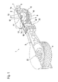
- Fig. 1 shows a Reibradspanner 1 according to the invention in a three-dimensional representation with a housing 2 and a boom 3, facing away from the housing 2 Side a friction wheel 4 is rotatably mounted.
- the housing 2 takes an eccentric 5 on, on a tubular, upstanding from the center of the housing 2 connecting piece 6 of the Housing 2 is pushed and with its lower end 7 in a hole or an eye 8 of the boom 3 engages.
- an electric motor 9 Within the tubular housing stub 6 is an electric motor 9 arranged. Above the electric motor 9, an eddy current clutch 10 is mounted, which has a pinion 11 on its upper side.
- the pinion 11 is connected via a gear transmission 12 with the eccentric 5 in operative connection by one of the gears 13 of the Gear transmission 12 engages in an internal toothing 14 of the eccentric 5, which on the inside 15 of the annular, enlarged in diameter relative to the eccentric 5 upper Part 16 of the eccentric 5 is attached.
- a helical return spring 17 lies outside the eccentric 5 around and is connected to one end 18 of the eddy current coupling 9, with the other end 19 attached to the boom 3.
- the boom is in an opening 20 of the Housing 2 guided linearly displaceable.
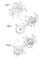
- Fig. 3 shows the open housing 2 with rotatably mounted inside the housing stub 6 Electric motor 9.
- the electric motor 9 has a long, upstanding Wave 21 up.
- the end of the boom is a bearing journal 22 arranged to receive the friction wheel 4.
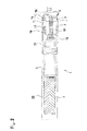
- Fig. 4 shows the opened housing 2 with mounted return spring 17 and pushed Eccentric 5.
- the eddy current clutch 10 is above the electric motor 9 within the Housing socket 6 mounted and rotatably connected to the long shaft 21 of the electric motor 9.
- the friction wheel 4 is rotatably mounted on the bearing pin 22.
- the shaft 21 of the electric motor 9 rotates in a first direction of rotation, this rotation transmitted to the pinion 11 via the eddy current coupling 10. Possible torque fluctuations are mitigated by the eddy current coupling 10.
- the eddy current coupling 10 is effective only during the rotation of the shaft 21.
- the pinion 11 transmits the rotation of the eddy current clutch 10 via the gear transmission 12 and the Internal toothing 14 of the eccentric 5 on the eccentric 5. It rotates the eccentric. 5 in the eye 8 of the boom 3.
- the boom 3 is thereby in the opening 20 of the housing 2 linearly displaced out of the housing 2 out.
Landscapes
- Engineering & Computer Science (AREA)
- General Engineering & Computer Science (AREA)
- Mechanical Engineering (AREA)
- Jib Cranes (AREA)
- Devices For Conveying Motion By Means Of Endless Flexible Members (AREA)
- One-Way And Automatic Clutches, And Combinations Of Different Clutches (AREA)
- Gear Transmission (AREA)
Abstract
Description
Die Erfindung betrifft einen ausrückbaren Reibradspanner mit folgenden Merkmalen:
- ein Gehäuse
- eine Reibradaufnahme, die als verstellbarer linear geführter Ausleger ausgebildet ist,
- ein an der Reibradaufnahme drehbar befestigtes Reibrad,
- der Ausleger ist durch einen drehbaren Exzenter linear in das Gehäuse hinein oder aus dem Gehäuse heraus verlagerbar, wobei der Exzenter innerhalb einer Bohrung des Auslegers angeordnet ist und mit diesem in Wirkverbindung steht,
- der Exzenter ist durch eine Verstelleinrichtung verdrehbar,
- die Verstelleinrichtung weist einen Elektromotor und eine Rückholfeder auf, wobei der Exzenter durch den Elektromotor in eine Drehrichtung, durch die Rückholfeder in die andere Drehrichtung verdrehbar ist.
- a housing
- a Reibradaufnahme, which is designed as an adjustable linear guided boom,
- a friction wheel rotatably mounted on the friction wheel receiver,
- the cantilever is displaceable linearly into or out of the housing by a rotatable eccentric, wherein the eccentric is arranged within a bore of the cantilever and is in operative connection therewith,
- the eccentric is rotatable by an adjustment,
- the adjusting device has an electric motor and a return spring, wherein the eccentric is rotated by the electric motor in a rotational direction by the return spring in the other direction of rotation.
Reibradspanner dienen dazu, ein Reibrad in einem Reibradgetriebe an seinen Rotationspartner, meist ein Antriebsrad zu drücken. Dabei ist das Reibrad des Reibradspanners meist durch Federkraft an das Antriebsrad gepresst. Die Federkraft kann durch Zug- oder Druckfedern erzeugt werden, aber auch durch eine Spiralfeder, die im Drehpunkt eines Auslegers ein Drehmoment ausübt. An dem Ausleger ist an dem dem Drehpunkt gegenüber liegenden Ende das Reibrad angebracht. Derartige Reibradspanner bewirken einen dauernden Eingriff des Reibrades mit dem Antriebsrad.Reibradspanner serve a friction wheel in a friction gear to its rotation partner, usually a drive wheel to press. The friction wheel of Reibradspanners is usually pressed by spring force to the drive wheel. The spring force can be by tension or compression springs be generated, but also by a coil spring in the pivot point of a boom exerts a torque. On the boom is at the pivot point opposite End of the friction wheel attached. Such Reibradspanner cause a permanent engagement of the friction wheel with the drive wheel.
Ausrückbare Reibradspanner dienen dazu, den Reibschluss zwischen Reibrad und Antriebsrad reversibel zu unterbrechen, um zum Beispiel Nebenaggregate eines Kraftfahr zeugmotors, wie Wasserpumpe, Servolenkungspumpe etc. bei Nichtgebrauch abschalten zu können, um Energie zu sparen.Disengageable Reibradspanner serve to the frictional engagement between the friction wheel and the drive wheel reversible to interrupt, for example, ancillaries of a motor vehicle motor, such as water pump, power steering pump, etc. when not in use switch off to be able to save energy.
Das An- bzw. Abkoppeln des Reibrades vom Antriebsrad muss einerseits schnell ablaufen, damit unnötiger Verschleiß des Reibrades vermieden wird, andererseits muss die Anpressung des Reibrades an das Antriebsrad ausreichen, ein gefordertes Nenndrehmoment zu übertragen und einen gleichmäßigen, drehschwingungsarmen Lauf des Getriebes zu ermöglichen.The coupling or uncoupling of the friction wheel from the drive wheel must on the one hand run fast, so that unnecessary wear of the friction wheel is avoided, on the other hand, the contact pressure of the friction wheel to the drive wheel sufficient, a required nominal torque transmit and allow a smooth, low-vibration running of the transmission.
Ein interner, bisher nicht veröffentlichter Lösungsansatz weist eine als verstellbarer, geführter Ausleger ausgebildete Reibradaufnahme auf, die das drehbar befestigte Reibrad durch lineare Verlagerung des Auslegers aus einem Gehäuse heraus oder in das Gehäuse hinein mit einem Antriebsrad in Eingriff bringt oder vom Antriebsrad abkoppelt. Der Ausleger wird dadurch verlagert, dass er über den sich drehenden Exzenter der Verstelleinrichtung aus dem Gehäuse herausgeschoben oder in das Gehäuse hineingezogen wird. Die Verdrehung des Exzenters geschieht durch den Elektromotor. Die Rückstellfeder sorgt bei Abschaltung des Stromes am Elektromotor für die Rückdrehung.An internal, previously unpublished approach has one as an adjustable, guided one Boom trained Reibradaufnahme on which the rotatably mounted friction wheel by linear displacement of the boom out of a housing or into the housing engages with a drive wheel or decoupled from the drive wheel. Of the Boom is displaced by passing over the rotating eccentric of the adjustment pushed out of the housing or pulled into the housing. The Rotation of the eccentric is done by the electric motor. The return spring provides Disconnection of the current at the electric motor for the reverse rotation.
Diese Anordnung setzt einen präzise arbeitenden, sehr langsam drehenden Elektromotor mit hohem Drehmoment voraus. Außerdem muß der Motor für die Rückdrehung des Exzenters bei Ausschalten des Stromes praktisch bremsmomentfrei sein, da die Rückholfeder sonst zu stark ausgelegt werden muß oder eine zuverlässige Abkoppelung des Reibrades vom Antriebsrad nicht gewährleistet ist. Die Bremsmomentfreiheit ist jedoch auch bei sehr aufwendigen Elektromotoren nicht vollständig gewährleistet. Außerdem verursachen langsamdrehende Elektromotore mit hohem Drehmoment sehr hohe Kosten.This arrangement uses a precise working, very slowly rotating electric motor with high torque ahead. In addition, the motor for the reverse rotation of the eccentric When switching off the current practically be free of braking torque, since the return spring otherwise it must be designed too strong or a reliable decoupling of the friction wheel is not guaranteed by the drive wheel. The Bremsmomentfreiheit is also at very much elaborate electric motors are not completely guaranteed. Moreover, slow-speed ones cause Electric motors with high torque very high costs.
Der Erfindung liegt daher die Aufgabe zugrunde, einen Exzenterantrieb für einen verstellbaren Reibradspanner zu schaffen, der im stromlosen Zustand die Rückdrehung des Exzenters nicht behindert und mit einem einfachen, kostengünstigen Elektromotor betrieben werden kann. The invention is therefore based on the object, an eccentric drive for an adjustable To provide Reibradspanner that in the de-energized state, the reverse rotation of the eccentric not hindered and operated with a simple, inexpensive electric motor can be.
Diese Aufgabe wird dadurch gelöst, dass die Verstelleinrichtung eine Wirbelstromkupplung aufweist, wobei der Elektromotor der Verstelleinrichtung über die Wirbelstromkupplung und das Getriebe mit dem Exzenter in Wirkverbindung steht.This object is achieved in that the adjusting device an eddy current coupling wherein the electric motor of the adjusting device via the eddy current coupling and the transmission is in operative connection with the eccentric.
Diese erfmdungsgemäße Anordnung hat den Vorteil, dass der Elektromotor über die Wirbelstromkupplung auf den Exzenter einwirkt. Wird der Strom am Elektromotor und der Wirbelstromkupplung abgeschaltet, ist eine vollständige mechanische Entkopplung von Elektromotor und Exzenter erreichbar.This erfmdungsgemäße arrangement has the advantage that the electric motor via the eddy current coupling acting on the eccentric. Is the current at the electric motor and the Eddy current coupling is switched off, is a complete mechanical decoupling of Electric motor and eccentric reachable.
In einer weiteren Ausbildung der Erfindung ist zwischen Wirbelstromkupplung und Exzenter der Verstelleinrichtung ein Zahnradgetriebe angeordnet.In a further embodiment of the invention is between eddy current coupling and eccentric the adjusting a gear transmission arranged.
Durch die Zwischenschaltung des Getriebes kann bei genügend großer Untersetzung auch ein kostengünstiger schnelllaufender Elektromotor mit geringem Drehmoment eingesetzt werden. Dabei sind auch während des Verstellens, also während der Drehung des Motors, die Abweichungen von einem gleichmäßigen Lauf des Motors durch die Verwendung des Getriebes und der Wirbelstromkupplung von geringem Einfluss auf die Funktion des Reibradspanners. Die Verwendung eines teuren, langsamlaufenden Elektromotors mit hohem Drehmoment, der den Exzenter direkt antreibt, ist daher nicht erforderlich.By the interposition of the transmission can also sufficiently large reduction a low-cost, low-speed, high-speed electric motor is used become. It is also during the adjustment, so during the rotation of the engine, the deviations from a smooth running of the engine through the use of the Transmission and the eddy current coupling of little influence on the function of Reibradspanners. The use of an expensive, low-speed electric motor with high Torque that drives the eccentric directly is therefore not required.
Anhand der Zeichnung wird nachstehend ein Ausführungsbeispiel der Erfindung näher erläutert. Es zeigt
- Fig. 1
- einen Reibradspanner in dreidimensionaler Darstellung als aufgeschnittenes Modell,
- Fig. 2
- den Reibradspanner aus Fig. 1 als Querschnitt
- Fig. 3
- das Gehäuse des Reibradspanners mit einem Elektromotor ohne Kupplung, Getriebe und Verstelleinheit,
- Fig. 4
- das Gehäuse aus Fig. 3 mit montierter Kupplung, Rückholfeder und Verstelleinheit und
- Fig. 5
- das komplett montierte Gehäuse des Reibradspanners.
- Fig. 1
- a Reibradspanner in three-dimensional representation as a sliced model,
- Fig. 2
- the Reibradspanner of Fig. 1 as a cross section
- Fig. 3
- the housing of Reibradspanners with an electric motor without clutch, transmission and adjustment,
- Fig. 4
- the housing of FIG. 3 with mounted clutch, return spring and adjustment and
- Fig. 5
- the completely assembled housing of the friction wheel tensioner.
Fig. 1 zeigt einen erfindungsgemäßen Reibradspanner 1 in einer dreidimensionalen Darstellung
mit einem Gehäuse 2 und einem Ausleger 3, an dessen dem Gehäuse 2 abgewandten
Seite ein Reibrad 4 drehbar gelagert ist. Das Gehäuse 2 nimmt einen Exzenter 5
auf, der auf einen rohrförmigen, aus der Mitte des Gehäuses 2 aufragenden Stutzen 6 des
Gehäuses 2 aufgeschoben ist und mit seinem unteren Ende 7 in eine Bohrung oder ein Auge
8 des Auslegers 3 greift. Innerhalb des rohrförmigen Gehäusestutzens 6 ist ein Elektromotor
9 angeordnet. Oberhalb des Elektromotors 9 ist eine Wirbelstromkupplung 10 angebracht,
die an ihrer Oberseite ein Ritzel 11 aufweist. Das Ritzel 11 steht über ein Zahnradgetriebe
12 mit dem Exzenter 5 in Wirkverbindung, indem eines der Zahnräder 13 des
Zahnradgetriebes 12 in eine Innenverzahnung 14 des Exzenters 5 greift, die an der Innenseite
15 des ringförmigen, im Durchmesser gegenüber dem Exzenter 5 erweiterten oberen
Teil 16 des Exzenters 5 angebracht ist. Eine spiralförmige Rückholfeder 17 liegt außen um
den Exzenter 5 herum und ist mit einem Ende 18 an der Wirbelstromkupplung 9, mit dem
anderen Ende 19 an dem Ausleger 3 befestigt. Der Ausleger ist in einer Öffnung 20 des
Gehäuses 2 linear verschieblich geführt.Fig. 1 shows a Reibradspanner 1 according to the invention in a three-dimensional representation
with a
In Fig. 2 sind die genannten Einzelteile des Reibradspanners 1 noch einmal in einem Querschnitt dargestellt.In Fig. 2, the above-mentioned individual parts of the Reibradspanners 1 once again in a cross section shown.
Fig. 3 zeigt das geöffnete Gehäuse 2 mit im Inneren des Gehäusestutzens 6 drehfest angebrachten
Elektromotor 9. Der Elektromotor 9 weist eine lange, nach oben herausragende
Welle 21 auf. An dem dem Gehäuse 2 abgewanden Ende des Auslegers ist ein Lagerzapfen
22 zur Aufnahme des Reibrades 4 angeordnet.Fig. 3 shows the
Fig. 4 zeigt das geöffnete Gehäuse 2 mit montierter Rückholfeder 17 und aufgeschobenem
Exzenter 5. Die Wirbelstromkupplung 10 ist oberhalb des Elektromotors 9 innerhalb des
Gehäusestutzens 6 montiert und drehfest mit der langen Welle 21 des Elektromotors 9 verbunden.Fig. 4 shows the opened
In Fig 5 ist das Reibrad 4 auf dem Lagerzapfen 22 drehbar angebracht. Zwischen dem Ritzel
11 der Wirbelstromkupplung 10 und der Innenverzahnung 14 des Exzenters 5 ist das
Zahnradgetriebe 12 mit einer Untersetzung von Ü = 1:100 angeordnet.In Fig 5, the
Dreht sich die Welle 21 des Elektromotors 9 in eine erste Drehrichtung, wird diese Rotation
über die Wirbelstromkupplung 10 auf das Ritzel 11 übertragen. Eventuelle Drehmomentschwankungen
werden durch die Wirbelstromkupplung 10 abgemildert. Die Wirbelstromkupplung
10 ist nur während der Rotation der Welle 21 wirksam. Das Ritzel 11 überträgt
die Rotation des Wirbelstromkupplung 10 über das Zahnradgetriebe 12 und die
Innenverzahnung 14 des Exzenters 5 auf den Exzenter 5. Dabei dreht sich der Exzenter 5
im Auge 8 des Auslegers 3. Der Ausleger 3 wird dadurch in der Öffnung 20 des Gehäuses
2 linear aus dem Gehäuse 2 heraus verlagert.The
Wird der Strom am Elektromotor 9 und der Wirbelstromkupplung 10 abgeschaltet, wird
über die Rückholfeder 17 der Exzenter 4 zurückgedreht und damit der Ausleger 3 in das
Gehäuse 2 linear zurückgezogen. Damit wird das Reibrad 3 vom hier nicht gezeigten Antriebsrad
abgekoppelt. If the current at the
- 11
- ReibradspannerReibradspanner
- 22
- Gehäusecasing
- 33
- Auslegerboom
- 44
- Reibradfriction wheel
- 55
- Exzentereccentric
- 66
- GehäusestutzenThe connection piece
- 77
- unteres Ende des Exzenters 5lower end of the eccentric 5
- 88th
-
Auge des Auslegers 3Eye of the
jib 3 - 99
- Elektromotorelectric motor
- 1010
- WirbelstromkupplungEddy current clutch
- 1111
- Ritzelpinion
- 1212
- Zahnradgetriebegear transmission
- 1313
- Zahnrädergears
- 1414
- Innenverzahnung des Exzenters 5Internal toothing of the eccentric 5
- 1515
- Innenseite des Exzenters 5Inside of the eccentric 5
- 1616
- oberes Teil des Exzentersupper part of the eccentric
- 1717
- Rückholfederreturn spring
- 1818
- kupplungsseitiges Ende der Rückstellfeder 18coupling-side end of the return spring 18th
- 1919
- auslegerseitiges Ende der Rückstellfeder 18boom-side end of the return spring 18th
- 2020
-
Welle des Elektromotors 8Shaft of the
electric motor 8 - 2121
-
Öffnung des Gehäuses 2Opening of the
housing 2 - 2222
- Lagerzapfenpivot
Claims (2)
Applications Claiming Priority (2)
| Application Number | Priority Date | Filing Date | Title |
|---|---|---|---|
| DE102004006793A DE102004006793A1 (en) | 2004-02-12 | 2004-02-12 | Disengageable friction wheel tensioner |
| DE102004006793 | 2004-02-12 |
Publications (3)
| Publication Number | Publication Date |
|---|---|
| EP1564443A2 true EP1564443A2 (en) | 2005-08-17 |
| EP1564443A3 EP1564443A3 (en) | 2006-01-18 |
| EP1564443B1 EP1564443B1 (en) | 2007-05-09 |
Family
ID=34684010
Family Applications (1)
| Application Number | Title | Priority Date | Filing Date |
|---|---|---|---|
| EP05100698A Expired - Lifetime EP1564443B1 (en) | 2004-02-12 | 2005-02-02 | Releasable friction wheel tensioner |
Country Status (3)
| Country | Link |
|---|---|
| EP (1) | EP1564443B1 (en) |
| AT (1) | ATE362061T1 (en) |
| DE (2) | DE102004006793A1 (en) |
Cited By (3)
| Publication number | Priority date | Publication date | Assignee | Title |
|---|---|---|---|---|
| US6290812B1 (en) | 1998-03-02 | 2001-09-18 | Kemira Kemi Ab | Method for treating process water in connection with pulp bleaching |
| US6746568B1 (en) | 1998-04-08 | 2004-06-08 | Kemira Kemi Ab | Treatment of filtrates from peroxide bleaching of pulp |
| EP1696151A1 (en) * | 2005-02-28 | 2006-08-30 | Dayco Europe S.r.l. con Unico Socio | Friction wheel actuator |
Family Cites Families (5)
| Publication number | Priority date | Publication date | Assignee | Title |
|---|---|---|---|---|
| DE373816C (en) * | 1923-04-16 | Oskar Simmen | Friction gear transmission | |
| FR1055657A (en) * | 1952-05-10 | 1954-02-22 | Gear for the interruptible transmission of force in motor vehicles and in stationary motive power installations | |
| DE1810126U (en) * | 1960-02-24 | 1960-04-21 | Henschel Werke G M B H | FRICTION WHEEL DRIVE FOR AUXILIARY DRIVES ON VEHICLE ENGINES. |
| DE19630221C1 (en) * | 1996-07-26 | 1997-08-28 | Daimler Benz Ag | Friction wheel drive for engine starter |
| DE10236746A1 (en) * | 2002-08-10 | 2004-02-19 | Bayerische Motoren Werke Ag | Internal combustion engine with a drive arrangement for unit modules |
-
2004
- 2004-02-12 DE DE102004006793A patent/DE102004006793A1/en not_active Withdrawn
-
2005
- 2005-02-02 AT AT05100698T patent/ATE362061T1/en not_active IP Right Cessation
- 2005-02-02 EP EP05100698A patent/EP1564443B1/en not_active Expired - Lifetime
- 2005-02-02 DE DE502005000672T patent/DE502005000672D1/en not_active Expired - Lifetime
Non-Patent Citations (1)
| Title |
|---|
| None |
Cited By (4)
| Publication number | Priority date | Publication date | Assignee | Title |
|---|---|---|---|---|
| US6290812B1 (en) | 1998-03-02 | 2001-09-18 | Kemira Kemi Ab | Method for treating process water in connection with pulp bleaching |
| US6746568B1 (en) | 1998-04-08 | 2004-06-08 | Kemira Kemi Ab | Treatment of filtrates from peroxide bleaching of pulp |
| EP1696151A1 (en) * | 2005-02-28 | 2006-08-30 | Dayco Europe S.r.l. con Unico Socio | Friction wheel actuator |
| WO2006089960A1 (en) * | 2005-02-28 | 2006-08-31 | Dayco Europe S.R.L. | Friction wheel actuator |
Also Published As
| Publication number | Publication date |
|---|---|
| EP1564443B1 (en) | 2007-05-09 |
| DE502005000672D1 (en) | 2007-06-21 |
| ATE362061T1 (en) | 2007-06-15 |
| EP1564443A3 (en) | 2006-01-18 |
| DE102004006793A1 (en) | 2005-09-08 |
Similar Documents
| Publication | Publication Date | Title |
|---|---|---|
| DE602004009688T2 (en) | VALVE DRIVE MECHANISM | |
| DE69504907T2 (en) | Adjustment device of the mirror housing of a vehicle rear view mirror. | |
| DE4036451A1 (en) | ENGINE-DRIVEN, SWIVELING EXTERNAL MIRROR FOR VEHICLES | |
| DE102008052846A1 (en) | Exhaust flap drive for a motor vehicle | |
| DE102005047203A1 (en) | Internal combustion engine with variable compression ratio | |
| DE19957791A1 (en) | Hydraulic drill drive | |
| DE102014114071A1 (en) | Electric drive for a medical device | |
| EP1564443B1 (en) | Releasable friction wheel tensioner | |
| DE2732987A1 (en) | DRILL WITH ROTARY DRIVE CONTROL | |
| DE69916861T2 (en) | POWER GEAR WITH MULTIPLE PLANETARY WHEEL DRIVES | |
| EP2011703A2 (en) | Windscreen wiper device | |
| EP1903256B1 (en) | Powered swivel drive | |
| DE2741475C2 (en) | Electric adjusting device | |
| DE10236022B4 (en) | Intake air throttle valve device | |
| DE60001038T2 (en) | Torque-controlled disc brake | |
| EP1881922B1 (en) | Pump drive for the pump of a retarder | |
| DE3412026C2 (en) | Coupling with load torque lock | |
| DE10393512B4 (en) | Device for operating a motor vehicle, in particular for actuating an automated transmission of a motor vehicle | |
| EP1903235A2 (en) | Assembly for operating a clutch of a vehicle | |
| EP2117394B1 (en) | Traction mechanism drive for a household appliance | |
| DE10254125B4 (en) | Electromotive furniture drive for adjusting parts of a furniture relative to each other | |
| EP1480859B1 (en) | Windscreen wiper device, in particular for a motor vehicle | |
| DE20112030U1 (en) | 2-speed gearbox for remote-controlled model cars | |
| EP4047164A1 (en) | Drive for an apparatus, arrangement and domestic appliance | |
| DE19957304A1 (en) | Actuator unit for operating motor vehicle gearbox and clutch structures has clutch and gearbox operating motors with output sections each rotating around swivelling axes parallel to each other. |
Legal Events
| Date | Code | Title | Description |
|---|---|---|---|
| PUAI | Public reference made under article 153(3) epc to a published international application that has entered the european phase |
Free format text: ORIGINAL CODE: 0009012 |
|
| AK | Designated contracting states |
Kind code of ref document: A2 Designated state(s): AT BE BG CH CY CZ DE DK EE ES FI FR GB GR HU IE IS IT LI LT LU MC NL PL PT RO SE SI SK TR |
|
| AX | Request for extension of the european patent |
Extension state: AL BA HR LV MK YU |
|
| PUAL | Search report despatched |
Free format text: ORIGINAL CODE: 0009013 |
|
| AK | Designated contracting states |
Kind code of ref document: A3 Designated state(s): AT BE BG CH CY CZ DE DK EE ES FI FR GB GR HU IE IS IT LI LT LU MC NL PL PT RO SE SI SK TR |
|
| AX | Request for extension of the european patent |
Extension state: AL BA HR LV MK YU |
|
| 17P | Request for examination filed |
Effective date: 20060718 |
|
| AKX | Designation fees paid |
Designated state(s): AT BE BG CH CY CZ DE DK EE ES FI FR GB GR HU IE IS IT LI LT LU MC NL PL PT RO SE SI SK TR |
|
| GRAP | Despatch of communication of intention to grant a patent |
Free format text: ORIGINAL CODE: EPIDOSNIGR1 |
|
| GRAS | Grant fee paid |
Free format text: ORIGINAL CODE: EPIDOSNIGR3 |
|
| GRAA | (expected) grant |
Free format text: ORIGINAL CODE: 0009210 |
|
| AK | Designated contracting states |
Kind code of ref document: B1 Designated state(s): AT BE BG CH CY CZ DE DK EE ES FI FR GB GR HU IE IS IT LI LT LU MC NL PL PT RO SE SI SK TR |
|
| PG25 | Lapsed in a contracting state [announced via postgrant information from national office to epo] |
Ref country code: FI Free format text: LAPSE BECAUSE OF FAILURE TO SUBMIT A TRANSLATION OF THE DESCRIPTION OR TO PAY THE FEE WITHIN THE PRESCRIBED TIME-LIMIT Effective date: 20070509 |
|
| REG | Reference to a national code |
Ref country code: GB Ref legal event code: FG4D Free format text: NOT ENGLISH |
|
| REG | Reference to a national code |
Ref country code: CH Ref legal event code: EP |
|
| REG | Reference to a national code |
Ref country code: IE Ref legal event code: FG4D Free format text: LANGUAGE OF EP DOCUMENT: GERMAN |
|
| REF | Corresponds to: |
Ref document number: 502005000672 Country of ref document: DE Date of ref document: 20070621 Kind code of ref document: P |
|
| PG25 | Lapsed in a contracting state [announced via postgrant information from national office to epo] |
Ref country code: SE Free format text: LAPSE BECAUSE OF FAILURE TO SUBMIT A TRANSLATION OF THE DESCRIPTION OR TO PAY THE FEE WITHIN THE PRESCRIBED TIME-LIMIT Effective date: 20070809 |
|
| PG25 | Lapsed in a contracting state [announced via postgrant information from national office to epo] |
Ref country code: ES Free format text: LAPSE BECAUSE OF FAILURE TO SUBMIT A TRANSLATION OF THE DESCRIPTION OR TO PAY THE FEE WITHIN THE PRESCRIBED TIME-LIMIT Effective date: 20070820 |
|
| GBT | Gb: translation of ep patent filed (gb section 77(6)(a)/1977) |
Effective date: 20070802 |
|
| PG25 | Lapsed in a contracting state [announced via postgrant information from national office to epo] |
Ref country code: IS Free format text: LAPSE BECAUSE OF FAILURE TO SUBMIT A TRANSLATION OF THE DESCRIPTION OR TO PAY THE FEE WITHIN THE PRESCRIBED TIME-LIMIT Effective date: 20070909 |
|
| NLV1 | Nl: lapsed or annulled due to failure to fulfill the requirements of art. 29p and 29m of the patents act | ||
| ET | Fr: translation filed | ||
| PG25 | Lapsed in a contracting state [announced via postgrant information from national office to epo] |
Ref country code: PL Free format text: LAPSE BECAUSE OF FAILURE TO SUBMIT A TRANSLATION OF THE DESCRIPTION OR TO PAY THE FEE WITHIN THE PRESCRIBED TIME-LIMIT Effective date: 20070509 |
|
| REG | Reference to a national code |
Ref country code: IE Ref legal event code: FD4D |
|
| PG25 | Lapsed in a contracting state [announced via postgrant information from national office to epo] |
Ref country code: CZ Free format text: LAPSE BECAUSE OF FAILURE TO SUBMIT A TRANSLATION OF THE DESCRIPTION OR TO PAY THE FEE WITHIN THE PRESCRIBED TIME-LIMIT Effective date: 20070509 Ref country code: PT Free format text: LAPSE BECAUSE OF FAILURE TO SUBMIT A TRANSLATION OF THE DESCRIPTION OR TO PAY THE FEE WITHIN THE PRESCRIBED TIME-LIMIT Effective date: 20071009 Ref country code: DK Free format text: LAPSE BECAUSE OF FAILURE TO SUBMIT A TRANSLATION OF THE DESCRIPTION OR TO PAY THE FEE WITHIN THE PRESCRIBED TIME-LIMIT Effective date: 20070509 Ref country code: NL Free format text: LAPSE BECAUSE OF FAILURE TO SUBMIT A TRANSLATION OF THE DESCRIPTION OR TO PAY THE FEE WITHIN THE PRESCRIBED TIME-LIMIT Effective date: 20070509 Ref country code: BG Free format text: LAPSE BECAUSE OF FAILURE TO SUBMIT A TRANSLATION OF THE DESCRIPTION OR TO PAY THE FEE WITHIN THE PRESCRIBED TIME-LIMIT Effective date: 20070809 Ref country code: SI Free format text: LAPSE BECAUSE OF FAILURE TO SUBMIT A TRANSLATION OF THE DESCRIPTION OR TO PAY THE FEE WITHIN THE PRESCRIBED TIME-LIMIT Effective date: 20070509 Ref country code: IE Free format text: LAPSE BECAUSE OF FAILURE TO SUBMIT A TRANSLATION OF THE DESCRIPTION OR TO PAY THE FEE WITHIN THE PRESCRIBED TIME-LIMIT Effective date: 20070509 |
|
| PG25 | Lapsed in a contracting state [announced via postgrant information from national office to epo] |
Ref country code: SK Free format text: LAPSE BECAUSE OF FAILURE TO SUBMIT A TRANSLATION OF THE DESCRIPTION OR TO PAY THE FEE WITHIN THE PRESCRIBED TIME-LIMIT Effective date: 20070509 Ref country code: LT Free format text: LAPSE BECAUSE OF FAILURE TO SUBMIT A TRANSLATION OF THE DESCRIPTION OR TO PAY THE FEE WITHIN THE PRESCRIBED TIME-LIMIT Effective date: 20070509 |
|
| PLBE | No opposition filed within time limit |
Free format text: ORIGINAL CODE: 0009261 |
|
| STAA | Information on the status of an ep patent application or granted ep patent |
Free format text: STATUS: NO OPPOSITION FILED WITHIN TIME LIMIT |
|
| 26N | No opposition filed |
Effective date: 20080212 |
|
| PG25 | Lapsed in a contracting state [announced via postgrant information from national office to epo] |
Ref country code: IT Free format text: LAPSE BECAUSE OF FAILURE TO SUBMIT A TRANSLATION OF THE DESCRIPTION OR TO PAY THE FEE WITHIN THE PRESCRIBED TIME-LIMIT Effective date: 20070509 Ref country code: GR Free format text: LAPSE BECAUSE OF FAILURE TO SUBMIT A TRANSLATION OF THE DESCRIPTION OR TO PAY THE FEE WITHIN THE PRESCRIBED TIME-LIMIT Effective date: 20070810 |
|
| PG25 | Lapsed in a contracting state [announced via postgrant information from national office to epo] |
Ref country code: RO Free format text: LAPSE BECAUSE OF FAILURE TO SUBMIT A TRANSLATION OF THE DESCRIPTION OR TO PAY THE FEE WITHIN THE PRESCRIBED TIME-LIMIT Effective date: 20070509 |
|
| BERE | Be: lapsed |
Owner name: CONTITECH ANTRIEBSSYSTEME G.M.B.H. Effective date: 20080228 |
|
| PG25 | Lapsed in a contracting state [announced via postgrant information from national office to epo] |
Ref country code: MC Free format text: LAPSE BECAUSE OF NON-PAYMENT OF DUE FEES Effective date: 20080228 |
|
| PG25 | Lapsed in a contracting state [announced via postgrant information from national office to epo] |
Ref country code: EE Free format text: LAPSE BECAUSE OF FAILURE TO SUBMIT A TRANSLATION OF THE DESCRIPTION OR TO PAY THE FEE WITHIN THE PRESCRIBED TIME-LIMIT Effective date: 20070509 |
|
| PG25 | Lapsed in a contracting state [announced via postgrant information from national office to epo] |
Ref country code: BE Free format text: LAPSE BECAUSE OF NON-PAYMENT OF DUE FEES Effective date: 20080228 |
|
| PG25 | Lapsed in a contracting state [announced via postgrant information from national office to epo] |
Ref country code: AT Free format text: LAPSE BECAUSE OF NON-PAYMENT OF DUE FEES Effective date: 20080202 |
|
| PG25 | Lapsed in a contracting state [announced via postgrant information from national office to epo] |
Ref country code: CY Free format text: LAPSE BECAUSE OF FAILURE TO SUBMIT A TRANSLATION OF THE DESCRIPTION OR TO PAY THE FEE WITHIN THE PRESCRIBED TIME-LIMIT Effective date: 20070509 |
|
| REG | Reference to a national code |
Ref country code: CH Ref legal event code: PL |
|
| PG25 | Lapsed in a contracting state [announced via postgrant information from national office to epo] |
Ref country code: CH Free format text: LAPSE BECAUSE OF NON-PAYMENT OF DUE FEES Effective date: 20090228 Ref country code: LI Free format text: LAPSE BECAUSE OF NON-PAYMENT OF DUE FEES Effective date: 20090228 |
|
| PG25 | Lapsed in a contracting state [announced via postgrant information from national office to epo] |
Ref country code: HU Free format text: LAPSE BECAUSE OF FAILURE TO SUBMIT A TRANSLATION OF THE DESCRIPTION OR TO PAY THE FEE WITHIN THE PRESCRIBED TIME-LIMIT Effective date: 20071110 Ref country code: LU Free format text: LAPSE BECAUSE OF NON-PAYMENT OF DUE FEES Effective date: 20080202 |
|
| PG25 | Lapsed in a contracting state [announced via postgrant information from national office to epo] |
Ref country code: TR Free format text: LAPSE BECAUSE OF FAILURE TO SUBMIT A TRANSLATION OF THE DESCRIPTION OR TO PAY THE FEE WITHIN THE PRESCRIBED TIME-LIMIT Effective date: 20070509 |
|
| PGFP | Annual fee paid to national office [announced via postgrant information from national office to epo] |
Ref country code: FR Payment date: 20120227 Year of fee payment: 8 |
|
| PGFP | Annual fee paid to national office [announced via postgrant information from national office to epo] |
Ref country code: DE Payment date: 20120229 Year of fee payment: 8 |
|
| PGFP | Annual fee paid to national office [announced via postgrant information from national office to epo] |
Ref country code: GB Payment date: 20120221 Year of fee payment: 8 |
|
| GBPC | Gb: european patent ceased through non-payment of renewal fee |
Effective date: 20130202 |
|
| REG | Reference to a national code |
Ref country code: FR Ref legal event code: ST Effective date: 20131031 |
|
| REG | Reference to a national code |
Ref country code: DE Ref legal event code: R119 Ref document number: 502005000672 Country of ref document: DE Effective date: 20130903 |
|
| PG25 | Lapsed in a contracting state [announced via postgrant information from national office to epo] |
Ref country code: DE Free format text: LAPSE BECAUSE OF NON-PAYMENT OF DUE FEES Effective date: 20130903 Ref country code: FR Free format text: LAPSE BECAUSE OF NON-PAYMENT OF DUE FEES Effective date: 20130228 Ref country code: GB Free format text: LAPSE BECAUSE OF NON-PAYMENT OF DUE FEES Effective date: 20130202 |