EP1564416A2 - Ventil zur Regelung oder Steuerung eines Drucks - Google Patents
Ventil zur Regelung oder Steuerung eines Drucks Download PDFInfo
- Publication number
- EP1564416A2 EP1564416A2 EP04029753A EP04029753A EP1564416A2 EP 1564416 A2 EP1564416 A2 EP 1564416A2 EP 04029753 A EP04029753 A EP 04029753A EP 04029753 A EP04029753 A EP 04029753A EP 1564416 A2 EP1564416 A2 EP 1564416A2
- Authority
- EP
- European Patent Office
- Prior art keywords
- pressure
- valve
- control
- actuating element
- acted
- Prior art date
- Legal status (The legal status is an assumption and is not a legal conclusion. Google has not performed a legal analysis and makes no representation as to the accuracy of the status listed.)
- Withdrawn
Links
Images



Classifications
-
- G—PHYSICS
- G05—CONTROLLING; REGULATING
- G05D—SYSTEMS FOR CONTROLLING OR REGULATING NON-ELECTRIC VARIABLES
- G05D16/00—Control of fluid pressure
- G05D16/14—Control of fluid pressure with auxiliary non-electric power
- G05D16/16—Control of fluid pressure with auxiliary non-electric power derived from the controlled fluid
- G05D16/166—Control of fluid pressure with auxiliary non-electric power derived from the controlled fluid using pistons within the main valve
-
- F—MECHANICAL ENGINEERING; LIGHTING; HEATING; WEAPONS; BLASTING
- F15—FLUID-PRESSURE ACTUATORS; HYDRAULICS OR PNEUMATICS IN GENERAL
- F15B—SYSTEMS ACTING BY MEANS OF FLUIDS IN GENERAL; FLUID-PRESSURE ACTUATORS, e.g. SERVOMOTORS; DETAILS OF FLUID-PRESSURE SYSTEMS, NOT OTHERWISE PROVIDED FOR
- F15B13/00—Details of servomotor systems ; Valves for servomotor systems
- F15B13/02—Fluid distribution or supply devices characterised by their adaptation to the control of servomotors
- F15B13/04—Fluid distribution or supply devices characterised by their adaptation to the control of servomotors for use with a single servomotor
- F15B13/042—Fluid distribution or supply devices characterised by their adaptation to the control of servomotors for use with a single servomotor operated by fluid pressure
-
- G—PHYSICS
- G05—CONTROLLING; REGULATING
- G05D—SYSTEMS FOR CONTROLLING OR REGULATING NON-ELECTRIC VARIABLES
- G05D16/00—Control of fluid pressure
- G05D16/04—Control of fluid pressure without auxiliary power
- G05D16/10—Control of fluid pressure without auxiliary power the sensing element being a piston or plunger
- G05D16/101—Control of fluid pressure without auxiliary power the sensing element being a piston or plunger the controller being arranged as a multiple-way valve
Definitions
- the invention relates to a valve for controlling or controlling a pressure, which a valve member which, at least from a rest position in which the valve member is the passage between a primary port and a secondary port the valve is locked, in a working position in which this Passage is at least partially released, is movable, wherein the valve an actuating device having an actuating element, whose Displacement generated by pressurization transferable to the valve member is.
- Such a valve is z. B. from EP 1 146 268 of the Applicant known.
- a tool eg. As a welding tongs, on the one hand a workpiece with a fixed pressure and on the other side with a variable pressure is applied, taking into account in a welding tool is that the lower electrode also in different spatial positions always exerts the same force on the sheet.
- This is a double-acting Cylinder inserted on one side with a through a hand pressure reducer adjustable firm pressure and on the other hand with one over one Proportional valve adjustable variable pressure is applied.
- the lower electrode of the welding gun with the required pressure the sheet can be attached.
- the Pressure of the hand pressure reducer can be reduced to a sufficiently firm Pressurize the lower side of the sheet to be welded through to reach the lower electrode.
- valve is provided in an advantageous manner, which is characterized in that at the secondary terminal, the secondary medium exits at the pressure P 2 , which is directly correlated with the control pressure P S occurring at the control or regulating connection.
- Valves according to the invention are therefore particularly suitable for use in machine tools such as welding robots, in which a double-acting cylinder on its side with the control or regulating pressure P S and on the other side with a correlated thereto pressure must be applied.
- valve member on one side of the actuating element of the first actuator which is correlated with the control or regulating pressure P S
- the valve member on the other side of the actuating element of the second actuator which with the supply pressure P M is correlated, is charged.
- Such a two-sided admission of the valve member has the advantage that the individual actuators are relatively simple.
- a further advantageous development of the invention provides that the valve member acted upon only on one side by a double-acting actuator which is the function of the first or second actuator integrated. Such a measure has the advantage that thereby a relatively compact valve is made possible.
- a further advantageous embodiment of the invention provides that the second Actuating device or the double-acting actuator on her Supply pressure side is acted upon by a spring. Such a measure has the advantage that this one of the supplied supply medium independent minimum pressure is realized.
- valve according to the invention then allows the corresponding Automated pressure control to perform so that the previously required for this Adjustment of a hand pressure reducer is no longer necessary.
- FIG. 1 is now a valve generally designated 1 with a primary terminal 2 for a primary medium with a primary pressure P 1 and a secondary terminal 3 for a secondary medium with a secondary pressure P 2 , which need not necessarily be identical to the primary medium represented.
- a valve member 5 which is displaceably guided in the axial direction is arranged which, as described below, can be actuated by two actuators 31 and 41, each with an actuating element 21' or 31 '.
- a spring 11 acting on a lower part 5a of the valve member 5 causes the seat surface 6 to be pressed against the valve seat 7 of the primary connection 2 by the restoring force of the spring 11 without a corresponding loading of the valve member 5.
- the valve 1 further comprises a Tertiäranschluß 4 for a tertiary medium with a teritä réelle P 3 , which in turn need not necessarily be identical to the primary and / or the secondary medium.
- the tertiary 4 is used to vent the valve 1, such that in a venting position of the valve 1, a connection between the secondary terminal 3 and Tertiäranschluß 4 can be produced so that the secondary medium can escape via the Tertiäranschluß 4.
- valve seat 17 which is used with a seat 16 of the valve member having a circumferential seal 16a 5 interacts.
- the valve seat 17 is hereby again preferably as a Ring cutting edge formed so that in the closed state of the valve seat 17 a passage of the secondary medium or the tertiary medium from the secondary terminal 3 to Tertiäranschluß 4 and vice versa is prevented.
- valve member 5 An upper part 5c of the valve member 5 is replaced by the restoring force of another Spring 18 acted upon.
- a valve 1 is - as already mentioned - known from EP 1 146 268 and DE-U1 9 202 519, wherein for avoidance of repetitions regarding the further embodiment of such Valve 1 referred to the aforementioned publications and in these documents disclosed technical teaching explicitly by this reference in the The disclosure of the present application is to be included.
- a pressure P 2 P max -f (P S ) occurs when a control or regulating pressure P S is supplied via a control or regulating connection 20 and to the second actuator 31 'a maximum pressure P max is applied.
- valve 1 the first actuating element 21 ', which acts on the lower in Figure 1, the first end 5' of the valve member 5.
- the guided in a chamber 22 and opposite this chamber 22 by a circumferential seal 23 sealed actuator 21 ' is at its first pressurizing surface 21a with the supplied via the control and / or regulating connection 20, under the control or regulating pressure P S standing control or the control medium acted upon and the resulting displacement movement of the first actuating element 21 'in its chamber 22 is converted into a corresponding displacement of the valve member 5.
- the second actuating element 31' is in turn axially displaceably mounted in a corresponding chamber 32 and is provided by a peripheral sealing element 33 sealed from the chamber 32nd a first pressure application 31a of the second operating member 31 'is thereby subjected to the maximum pressure P max, which in the case described here, from the pressure P F, which is a (optional vorsehbare) spring 35 on the actuating element 31' exerted, and the pressure P M , which has a supplied via the supply port 30 supply medium, composed.
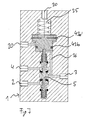
- FIG. 2 shows a second embodiment of a valve 1 is shown, which corresponds to its basic structure according to that of the first embodiment, so that corresponding components provided with the same reference numerals and will not be described in detail.
- the essential difference between the first and second embodiments is that in this case the spring 35 is no longer provided. Rather, in the second embodiment, the pressure P max is determined essentially exclusively by the pressure P M of the supply medium.
- the third embodiment shown in Figure 3 corresponds to its basic Structure according to again the first embodiment, so that also here - as well as in the following five embodiments - corresponding to each other Components provided with the same reference numerals and not described in detail become.
- the essential difference between the first and the third embodiment consists in the fact that the two actuating elements 21 ', 31', not - as in the first embodiment - designed as a piston, but as a membrane are, of course, also possible, only one of the two actuators 21 ', 31' as a piston and the other as a membrane train.
- the fourth embodiment shown in Figure 4 corresponds to its basic Structure according to again the second embodiment, with the proviso that also here the actuating elements 21 'and 31' formed as a membrane are.
- FIG. 5 now shows a fifth exemplary embodiment of a valve 1 which differs from the embodiments of FIGS. 1-4, that now no longer separate, the valve member 5 at one end 5 ', 5 "acting actuators 21, 31 are provided
- Embodiment of the valve 1 is rather constructed such that one end, in the case shown here, the upper end 5 ", the valve member 5 of a double-acting Actuator 41 ', which in the case shown here as a piston is trained, is acted upon.
- the actuator 41 thus provides in functionally the combination of the actuators 21 and 31st
- the two actuating elements 21 'and 31' are thus in the actuating element 41 'of the actuator 41 structurally and functionally summarized.
- the actuating element 41 'of the actuating device 41 is displaceably guided in a chamber 42 and is sealed off from the chamber 42 via two seals 43a and 43b.
- the actuating element 41 in turn has a first pressurizing surface 41a, whose function corresponds to the surface 31a of the actuating element 31 'of the first four embodiments. On the first pressurizing surface 41a thus the pressure P max acts.
- a second pressurizing surface 41 b is arranged, the function of which in turn corresponds to the second pressurizing surface 31 b of the actuating element 31' of the first four embodiments, so that this second pressurizing surface 41 b in the open passage between the primary terminal 2 and secondary terminal 3 via the connecting line 36 with the pressure P 1 is applied.
- the actuating element 41 ' still has a third pressurizing surface 41c, whose function corresponds to the pressurizing surface 21a of the first actuating element 21'.
- the control port 20 is directly led to the third pressurizing surface 41c, so that the pressurizing surface 41c is supplied with the control pressure P S.
- the sixth embodiment differs in turn characterized in that in this case the spring eliminates 35 of the fifth embodiment of Figure 5, so that the first pressure application 41a pressure applied substantially by the pressure P M of the air supplied via the supply terminal 30 medium is determined ,
- the seventh embodiment of Figure 7 differs from the fifth embodiment Figure 5 again by the fact that instead of the circulating Dichung 43 a membrane 43a 'the sealing function between actuator 41 'and the chamber 42 takes over.
- the eighth embodiment of Figure 8 corresponds essentially to the embodiment 6, wherein in turn instead of the seal 43 a Membrane 43a 'is used.
Landscapes
- Physics & Mathematics (AREA)
- Engineering & Computer Science (AREA)
- Fluid Mechanics (AREA)
- General Physics & Mathematics (AREA)
- Automation & Control Theory (AREA)
- Power Engineering (AREA)
- Mechanical Engineering (AREA)
- General Engineering & Computer Science (AREA)
- Control Of Fluid Pressure (AREA)
Abstract
Description
- Figur 1:
- Ein erstes Ausführungsbeispiel eines Druckregel- oder Drucksteuerventils,
- Figur 2:
- ein zweites Ausführungsbeispiel eines Druckregel- oder Drucksteuerventils,
- Figur 3:
- ein drittes Ausführungsbeispiel eines Druckregel- oder Drucksteuerventils,
- Figur 4:
- ein viertes Ausführungsbeispiel eines Druckregel- oder Drucksteuerventils,
- Figur 5:
- ein fünftes Ausführungsbeispiel eines Druckregel- oder Drucksteuerventils,
- Figur 6:
- ein sechstes Ausführungsbeispiel eines Druckregel- oder Drucksteuerventils,
- Figur 7:
- ein siebtes Ausführungsbeispiel eines Druckregel- oder Drucksteuerventils,
- Figur 8:
- ein achtes Ausführungsbeispiel eines Druckregel- oder Drucksteuerventils.
Claims (15)
- Ventil zur Regelung oder Steuerung eines Drucks, welches ein Ventilglied (1) aufweist, das zumindest von einer Ruhestellung, in der durch das Ventilglied (5) der Durchgang zwischen einem Primäranschluß (2) und einem Sekundäranschluß (3) des Ventils (1) gesperrt ist, in eine Arbeitsstellung, in der dieser Durchgang zumindest teilweise freigegeben ist, bewegbar ist, wobei das Ventil (1) mindestens eine Betätigungseinrichtung (21, 31; 41) mit einem Betätigungselement (21', 31'; 41') aufweist, dessen durch eine Druckbeaufschlagung erzeugte Auslenkung auf das Ventilglied (5) übertragbar ist, dadurch gekennzeichnet, dass das Ventil (1) einen Steuer- oder Regelungseingang (20) aufweist, durch den dem Ventil (1) ein Steuer- oder Regelungsmedium mit einem Steuer- oder Regeldruck PS zuführbar ist, und einen Versorgungseingang (30), durch den dem Ventil (1) ein Versorgungsmedium mit einem Druck PM zuführbar ist, aufweist, dass durch ein Betätigungselement (21') einer ersten Betätigungseinrichtung (21) das Ventilglied (5) mit einer dem Steuer- oder Regeldruck PS entsprechenden Kraft FS und durch ein zweites Betätigungselement (31'; 41) einer zweiten Betätigungseinrichtung (31; 41) durch eine der Kraft FS entgegenwirkenden Kraft Fmax beaufschlagt wird, welche mit dem Druck PM des über den Versorgungseingang (30) zugeführten Versorgungsmediums korreliert ist, dass das zweite Betätigungselement (31') über eine vom Sekundäranschluß (3) abzweigende Verbindungsleitung (36) mit einer Kraft F1 beaufschlagbar ist, die mit dem Druck P1 des vom Primäranschluß (2) zum Sekundäranschluß (3) durchtretenden Primärmediums korreliert ist, und dass am Sekundäranschluß (3) das Sekundärmedium mit einem Druck P2 austritt, der gleich P2=Pmax-f (PS) ist, wobei f (PS) eine Funktion des Steuer- oder Regelungsdruckes PS ist.
- Ventil nach Anspruch 1, dadurch gekennzeichnet, dass ein erstes Ende (5') des Ventilglieds (5) von dem Betätigungselement (21') der ersten Betätigungseinrichtung (21) und dass dem ersten Ende (5') gegenüberliegende zweite Ende (5") des Ventilglieds (5) vom Betätigungselement (31') der zweiten Betätigungseinrichtung (31) beaufschlagt ist.
- Ventil nach einem der vorangehenden Ansprüche, dadurch gekennzeichnet, dass das Betätigungselement (21') der ersten Betätigungseinrichtung (21) eine Druckbeaufschlagungsfläche (21a) aufweist, die mit dem über den Steuer- oder Regelanschluß (20) zugeführten Steuer- oder Regelmedium mit dem Steuer- oder Regeldruck PS beaufschlagbar ist.
- Ventil nach einem der vorangehenden Ansprüche, dadurch gekennzeichnet, dass das Betätigungselement (31') der zweiten Betätigungseinrichtung (31) eine erste Druckbeaufschlagungsfläche (31a) aufweist, die mit dem über den Versorgungsanschluß (30) zugeführte Versorgungsmedium mit Druck PM beaufschlagbar ist.
- Ventil nach einem der vorangehenden Ansprüche, dadurch gekennzeichnet, dass die erste Druckbeaufschlagungsfläche (31a) des Betätigungselements (31') der zweiten Betätigungseinrichtung (31) durch eine Feder (35) mit einem Druck PF beaufschlagbar ist.
- Ventil nach einem der vorangehenden Ansprüche, dadurch gekennzeichnet, dass das Betätigungselement (31') der zweiten Betätigungseinrichtung (31) eine zweite Druckbeaufschlagungsfläche (31b) aufweist, die mit dem über die Verbindungsleitung (36) zugeführten Primärmedium mit dem Druck P1 beaufschlagbar ist.
- Ventil nach Anspruch 1, dadurch gekennzeichnet, dass ein Ende (5") des Ventilglieds (5) von einem Betätigungselement (41) einer funktionell die erste Betätigungseinrichtung (21) und die zweite Betätigungseinrichtung (31) zusammenfassenden doppelwirkenden Betätigungseinrichtung (41) beaufschlagt ist.
- Ventil nach einem der vorangehenden Ansprüche, dadurch gekennzeichnet, dass die doppelwirkende Betätigungseinrichtung (41) eine erste Druckbeaufschlagungsfläche (41a), die mit dem Druck PM des über den Versorgungsanschluß (30) zugeführten Versorgungsmediums und/oder dem Druck PF der Feder (35) beaufschlagbar ist, eine zweite Druckbeaufschlagungsfläche (41b), die mit dem Druck P1 des über die Verbindungsleitung (36) zugeführten Primärmediums beaufschlagbar ist, und eine dritte Druckbeaufschlagungsfläche 41c, die mit dem über den Steuer- oder Regelanschluß (20) zugeführten Steuer- oder Regelungsmedium mit dem Steuer- oder Regelungsdruck PS beaufschlagbar ist, aufweist.
- Ventil nach einem der vorangehenden Ansprüche, dadurch gekennzeichnet, dass die die Betätigungselemente (21', 31', 41') in einer Kammer (22, 32, 42) verschiebbar geführt sind.
- Ventil nach einem der vorangehenden Ansprüche, dadurch gekennzeichnet, dass mindestens ein Betätigungselement (21', 31', 41') als ein Kolben ausgeführt ist.
- Ventil nach einem der vorangehenden Ansprüche, dadurch gekennzeichnet, dass mindestens ein Betätigungselement (21', 31', 41') als eine Membran ausgeführt ist.
- Ventil nach einem der vorangehenden Ansprüche, dadurch gekennzeichnet, dass die Fläche A1 der ersten Druckbeaufschlagungsfläche (21a) des Betätigungselements (21') der ersten Betätigungseinrichtung (21) gleich der Fläche A2 der ersten Druckbeaufschlagungsfläche (31a) des Betätigungselements (31') der zweiten Betätigungseinrichtung (31) ist.
- Ventil nach einem der vorangehenden Ansprüche, dadurch gekennzeichnet, dass die Fläche A1 der ersten Druckbeaufschlagungsfläche (41a) des doppelwirkenden Betätigungselements (41') der doppelwirkenden Betätigungseinrichtung (41) gleich der Fläche A2 der zweiten Druckbeaufschlagungsfläche (41b) und wiederum gleich der Fläche A3 der dritten Druckbeaufschlagungsfläche (41c) ist.
- Ventil nach einem der vorangehenden Ansprüche, dadurch gekennzeichnet, dass der untere Teil (5a) und/oder der obere Teil (5c) des Ventilglieds (5) durch eine rücktreibende Feder (11; 18) beaufschlagbar ist, welche bewirkt, dass ohne eine entsprechende Beaufschlagung des Ventilglieds (5) durch die Betätigungskraft (F) der Betätigungsvorrichtung (30) die Sitzfläche (6) des unteren Teils (5a) bzw. die Sitzfläche (16) des oberen Teils (5c) des Ventilglieds (5) gegen den Ventilsitz (7) des Primäranschlusses (2) bzw. den Ventilsitz (17) des Sekundäranschlusses (3) gepreßt wird.
- Ventil nach einem der vorangehenden Ansprüche, dadurch gekennzeichnet, dass das Ventil (1) einen Tertiäranschluß (4) aufweist.
Applications Claiming Priority (2)
| Application Number | Priority Date | Filing Date | Title |
|---|---|---|---|
| DE102004006811 | 2004-02-11 | ||
| DE102004006811A DE102004006811A1 (de) | 2004-02-11 | 2004-02-11 | Ventil zur Regelung oder Steuerung eines Drucks |
Publications (2)
| Publication Number | Publication Date |
|---|---|
| EP1564416A2 true EP1564416A2 (de) | 2005-08-17 |
| EP1564416A3 EP1564416A3 (de) | 2005-11-09 |
Family
ID=34684013
Family Applications (1)
| Application Number | Title | Priority Date | Filing Date |
|---|---|---|---|
| EP04029753A Withdrawn EP1564416A3 (de) | 2004-02-11 | 2004-12-16 | Ventil zur Regelung oder Steuerung eines Drucks |
Country Status (2)
| Country | Link |
|---|---|
| EP (1) | EP1564416A3 (de) |
| DE (1) | DE102004006811A1 (de) |
Cited By (1)
| Publication number | Priority date | Publication date | Assignee | Title |
|---|---|---|---|---|
| FR2925132A1 (fr) * | 2007-12-14 | 2009-06-19 | Ind Mecanique Pour Les Fluides | Soupape pilotee a trois voies avec clapet et composant moteur equilibres pour regulation de pression de fluide |
Families Citing this family (1)
| Publication number | Priority date | Publication date | Assignee | Title |
|---|---|---|---|---|
| DE102018208755A1 (de) * | 2018-06-04 | 2019-12-05 | Zf Friedrichshafen Ag | Druckregelventil |
Family Cites Families (5)
| Publication number | Priority date | Publication date | Assignee | Title |
|---|---|---|---|---|
| DE3625222A1 (de) * | 1986-07-25 | 1988-02-04 | Index Werke Kg Hahn & Tessky | Druckregler fuer hydraulisch gesteuerte werkzeugmaschinen |
| DE8631700U1 (de) * | 1986-11-27 | 1987-01-29 | Hans E. Winkelmann GmbH, 6074 Rödermark | Differenzflächen-Schaltventil |
| DE9202519U1 (de) * | 1992-02-27 | 1992-05-14 | Lanny, Michael, 7547 Wildbad | Ventil |
| FR2715484B1 (fr) * | 1994-01-21 | 1996-02-23 | Chateaudun Hydraulique | Servovalve de régulation de pression. |
| EP1146268A3 (de) * | 2000-04-10 | 2003-01-02 | MLS Lanny GmbH | Betätigungsvorrichtung für ein Ventilglied eines Ventils sowie ein derartiges Ventil |
-
2004
- 2004-02-11 DE DE102004006811A patent/DE102004006811A1/de not_active Ceased
- 2004-12-16 EP EP04029753A patent/EP1564416A3/de not_active Withdrawn
Cited By (1)
| Publication number | Priority date | Publication date | Assignee | Title |
|---|---|---|---|---|
| FR2925132A1 (fr) * | 2007-12-14 | 2009-06-19 | Ind Mecanique Pour Les Fluides | Soupape pilotee a trois voies avec clapet et composant moteur equilibres pour regulation de pression de fluide |
Also Published As
| Publication number | Publication date |
|---|---|
| EP1564416A3 (de) | 2005-11-09 |
| DE102004006811A1 (de) | 2005-09-08 |
Similar Documents
| Publication | Publication Date | Title |
|---|---|---|
| DE102005031411B4 (de) | Verfahren zur Steuerung eines zwischen zwei Vakuumkammern angeordneten Vakuumventils | |
| DE3114437C2 (de) | Druckregelventil | |
| DE202016008955U1 (de) | Membran mit geringer Hysterese für ein Ventil | |
| EP2960561A1 (de) | Hydraulikventil | |
| DE3305092A1 (de) | Druckregelventil | |
| DE2517244A1 (de) | Druckbetriebene abgabeduese | |
| EP1851098B9 (de) | Kombinierter federspeicher- und betriebsbremszylinder mit einer beatmungseinrichtung | |
| DD232532A5 (de) | Mehrwege-tellerventil | |
| DE102011119784A1 (de) | Fluidbetätigte Greifvorrichtung mit Sicherheitseinrichtung | |
| DE102013002452A1 (de) | Fluidtechnisches Gerät | |
| DE10010690B4 (de) | Ventil | |
| EP1564416A2 (de) | Ventil zur Regelung oder Steuerung eines Drucks | |
| EP1146268A2 (de) | Betätigungsvorrichtung für ein Ventilglied eines Ventils sowie ein derartiges Ventil | |
| DE102005027573A1 (de) | Durchflussratensteuervorrichtung | |
| DE102014207393B4 (de) | Ventil | |
| DE102004046976B4 (de) | Mehrwegeventil | |
| DE202004002109U1 (de) | Ventil zur Regelung oder Steuerung eines Drucks | |
| DE102006007995B4 (de) | Vorrichtung zur Positionierung einer Schweisszange | |
| DE2043337B2 (de) | Hydraulisches Servoventil | |
| EP0928892A1 (de) | Druckkompensiertes Abgasrückführventil | |
| EP2619057B1 (de) | Pneumatisches steuerventil mit mehreren c-kolben | |
| DE102010052532B4 (de) | Dämpfungsventil für eine Pneumatikantriebseinheit | |
| DE10336916B4 (de) | Regelventil und Wärmetauscheranordnung | |
| EP1998091B1 (de) | Pneumatische Steuereinrichtung für ein Drucklufthebezeug | |
| DE2300355A1 (de) | Differenzdruckbetaetigter kraftverstaerker |
Legal Events
| Date | Code | Title | Description |
|---|---|---|---|
| PUAI | Public reference made under article 153(3) epc to a published international application that has entered the european phase |
Free format text: ORIGINAL CODE: 0009012 |
|
| AK | Designated contracting states |
Kind code of ref document: A2 Designated state(s): AT BE BG CH CY CZ DE DK EE ES FI FR GB GR HU IE IS IT LI LT LU MC NL PL PT RO SE SI SK TR |
|
| AX | Request for extension of the european patent |
Extension state: AL BA HR LV MK YU |
|
| PUAL | Search report despatched |
Free format text: ORIGINAL CODE: 0009013 |
|
| AK | Designated contracting states |
Kind code of ref document: A3 Designated state(s): AT BE BG CH CY CZ DE DK EE ES FI FR GB GR HU IE IS IT LI LT LU MC NL PL PT RO SE SI SK TR |
|
| AX | Request for extension of the european patent |
Extension state: AL BA HR LV MK YU |
|
| 17P | Request for examination filed |
Effective date: 20060323 |
|
| AKX | Designation fees paid |
Designated state(s): AT BE BG CH CY CZ DE DK EE ES FI FR GB GR HU IE IS IT LI LT LU MC NL PL PT RO SE SI SK TR |
|
| STAA | Information on the status of an ep patent application or granted ep patent |
Free format text: STATUS: THE APPLICATION HAS BEEN WITHDRAWN |
|
| 18W | Application withdrawn |
Effective date: 20061222 |