EP1564406A2 - Dämpfungsfähiges Stehlager für Windkraftanlagen - Google Patents
Dämpfungsfähiges Stehlager für Windkraftanlagen Download PDFInfo
- Publication number
- EP1564406A2 EP1564406A2 EP05002470A EP05002470A EP1564406A2 EP 1564406 A2 EP1564406 A2 EP 1564406A2 EP 05002470 A EP05002470 A EP 05002470A EP 05002470 A EP05002470 A EP 05002470A EP 1564406 A2 EP1564406 A2 EP 1564406A2
- Authority
- EP
- European Patent Office
- Prior art keywords
- bearing
- pillow block
- elastomeric
- parts
- damping
- Prior art date
- Legal status (The legal status is an assumption and is not a legal conclusion. Google has not performed a legal analysis and makes no representation as to the accuracy of the status listed.)
- Granted
Links
- 238000013016 damping Methods 0.000 title claims abstract description 23
- 238000005096 rolling process Methods 0.000 claims description 17
- 229920001971 elastomer Polymers 0.000 claims description 11
- 239000000806 elastomer Substances 0.000 claims description 11
- 238000000465 moulding Methods 0.000 claims description 6
- 230000013011 mating Effects 0.000 claims description 2
- 238000003860 storage Methods 0.000 abstract description 3
- 230000003534 oscillatory effect Effects 0.000 abstract 1
- 239000000463 material Substances 0.000 description 8
- 239000004033 plastic Substances 0.000 description 5
- 229920003023 plastic Polymers 0.000 description 5
- 244000043261 Hevea brasiliensis Species 0.000 description 3
- 230000005540 biological transmission Effects 0.000 description 3
- 229920003052 natural elastomer Polymers 0.000 description 3
- 229920001194 natural rubber Polymers 0.000 description 3
- 229920000049 Carbon (fiber) Polymers 0.000 description 2
- 241000196324 Embryophyta Species 0.000 description 2
- 239000004917 carbon fiber Substances 0.000 description 2
- 239000002184 metal Substances 0.000 description 2
- VNWKTOKETHGBQD-UHFFFAOYSA-N methane Chemical compound C VNWKTOKETHGBQD-UHFFFAOYSA-N 0.000 description 2
- 239000007787 solid Substances 0.000 description 2
- 238000004026 adhesive bonding Methods 0.000 description 1
- 238000000418 atomic force spectrum Methods 0.000 description 1
- 239000002131 composite material Substances 0.000 description 1
- 230000000694 effects Effects 0.000 description 1
- 239000013536 elastomeric material Substances 0.000 description 1
- 239000004744 fabric Substances 0.000 description 1
- 238000009434 installation Methods 0.000 description 1
- 238000005304 joining Methods 0.000 description 1
- 238000000034 method Methods 0.000 description 1
- 239000000203 mixture Substances 0.000 description 1
- NJPPVKZQTLUDBO-UHFFFAOYSA-N novaluron Chemical group C1=C(Cl)C(OC(F)(F)C(OC(F)(F)F)F)=CC=C1NC(=O)NC(=O)C1=C(F)C=CC=C1F NJPPVKZQTLUDBO-UHFFFAOYSA-N 0.000 description 1
- 229920000642 polymer Polymers 0.000 description 1
- 238000002360 preparation method Methods 0.000 description 1
- 238000004073 vulcanization Methods 0.000 description 1
- XLYOFNOQVPJJNP-UHFFFAOYSA-N water Substances O XLYOFNOQVPJJNP-UHFFFAOYSA-N 0.000 description 1
Images


Classifications
-
- F—MECHANICAL ENGINEERING; LIGHTING; HEATING; WEAPONS; BLASTING
- F16—ENGINEERING ELEMENTS AND UNITS; GENERAL MEASURES FOR PRODUCING AND MAINTAINING EFFECTIVE FUNCTIONING OF MACHINES OR INSTALLATIONS; THERMAL INSULATION IN GENERAL
- F16C—SHAFTS; FLEXIBLE SHAFTS; ELEMENTS OR CRANKSHAFT MECHANISMS; ROTARY BODIES OTHER THAN GEARING ELEMENTS; BEARINGS
- F16C27/00—Elastic or yielding bearings or bearing supports, for exclusively rotary movement
- F16C27/06—Elastic or yielding bearings or bearing supports, for exclusively rotary movement by means of parts of rubber or like materials
-
- F—MECHANICAL ENGINEERING; LIGHTING; HEATING; WEAPONS; BLASTING
- F03—MACHINES OR ENGINES FOR LIQUIDS; WIND, SPRING, OR WEIGHT MOTORS; PRODUCING MECHANICAL POWER OR A REACTIVE PROPULSIVE THRUST, NOT OTHERWISE PROVIDED FOR
- F03D—WIND MOTORS
- F03D80/00—Details, components or accessories not provided for in groups F03D1/00 - F03D17/00
- F03D80/70—Bearing or lubricating arrangements
-
- F—MECHANICAL ENGINEERING; LIGHTING; HEATING; WEAPONS; BLASTING
- F16—ENGINEERING ELEMENTS AND UNITS; GENERAL MEASURES FOR PRODUCING AND MAINTAINING EFFECTIVE FUNCTIONING OF MACHINES OR INSTALLATIONS; THERMAL INSULATION IN GENERAL
- F16C—SHAFTS; FLEXIBLE SHAFTS; ELEMENTS OR CRANKSHAFT MECHANISMS; ROTARY BODIES OTHER THAN GEARING ELEMENTS; BEARINGS
- F16C19/00—Bearings with rolling contact, for exclusively rotary movement
- F16C19/22—Bearings with rolling contact, for exclusively rotary movement with bearing rollers essentially of the same size in one or more circular rows, e.g. needle bearings
- F16C19/24—Bearings with rolling contact, for exclusively rotary movement with bearing rollers essentially of the same size in one or more circular rows, e.g. needle bearings for radial load mainly
- F16C19/26—Bearings with rolling contact, for exclusively rotary movement with bearing rollers essentially of the same size in one or more circular rows, e.g. needle bearings for radial load mainly with a single row of rollers
-
- F—MECHANICAL ENGINEERING; LIGHTING; HEATING; WEAPONS; BLASTING
- F05—INDEXING SCHEMES RELATING TO ENGINES OR PUMPS IN VARIOUS SUBCLASSES OF CLASSES F01-F04
- F05B—INDEXING SCHEME RELATING TO WIND, SPRING, WEIGHT, INERTIA OR LIKE MOTORS, TO MACHINES OR ENGINES FOR LIQUIDS COVERED BY SUBCLASSES F03B, F03D AND F03G
- F05B2260/00—Function
- F05B2260/96—Preventing, counteracting or reducing vibration or noise
-
- F—MECHANICAL ENGINEERING; LIGHTING; HEATING; WEAPONS; BLASTING
- F16—ENGINEERING ELEMENTS AND UNITS; GENERAL MEASURES FOR PRODUCING AND MAINTAINING EFFECTIVE FUNCTIONING OF MACHINES OR INSTALLATIONS; THERMAL INSULATION IN GENERAL
- F16C—SHAFTS; FLEXIBLE SHAFTS; ELEMENTS OR CRANKSHAFT MECHANISMS; ROTARY BODIES OTHER THAN GEARING ELEMENTS; BEARINGS
- F16C2360/00—Engines or pumps
- F16C2360/31—Wind motors
-
- Y—GENERAL TAGGING OF NEW TECHNOLOGICAL DEVELOPMENTS; GENERAL TAGGING OF CROSS-SECTIONAL TECHNOLOGIES SPANNING OVER SEVERAL SECTIONS OF THE IPC; TECHNICAL SUBJECTS COVERED BY FORMER USPC CROSS-REFERENCE ART COLLECTIONS [XRACs] AND DIGESTS
- Y02—TECHNOLOGIES OR APPLICATIONS FOR MITIGATION OR ADAPTATION AGAINST CLIMATE CHANGE
- Y02E—REDUCTION OF GREENHOUSE GAS [GHG] EMISSIONS, RELATED TO ENERGY GENERATION, TRANSMISSION OR DISTRIBUTION
- Y02E10/00—Energy generation through renewable energy sources
- Y02E10/70—Wind energy
- Y02E10/72—Wind turbines with rotation axis in wind direction
Definitions
- the invention relates to a novel storage of rotors or rotor shafts of Wind turbines (pillow block), consisting essentially of one of the invention
- the pillow block according to the Invention is not only suitable for use in wind turbines, but also for other machinery and equipment which have similar vibration and force profiles exhibit.
- Wind turbines are naturally subject to additional and particularly pronounced Forces, which mainly by the rotor movement as such, especially in shape of imbalances, as well as by some extreme winds, the most diverse Directions to act on the rotor blades and the plant as a whole.
- the powertrain in wind turbines is often on by a three-point mounting stored the machine carrier.
- the forces and moments created on the rotor become among other things of a pillow block, which immediately behind the rotor blade is positioned and the rotor shaft receives transferred to the machine frame.
- the Rotor shaft usually opens in a gearbox and / or generator, which also have special bearings that another part of these forces and To compensate for vibrations. These bearings transmit the transmission, from the generator and the vibrations occurring in the pillow block bearing, in particular also the caused structure-borne noise on the machine frame and the tower of the wind turbine.
- the tower amplifies this structure-borne noise and radiates it as a disturbing airborne sound in the Environment. In the case of installations that are set up in the sea (off-shore), they transfer the sound into the water, where it spreads quickly and without great losses and itself negative impact on the development of marine life.
- Plummer blocks in wind turbines essentially consist of a plummer block housing and a rolling bearing according to the prior art.
- Spherical roller bearings are gimbaled movable, so that pitching and yawing movements of the rotor shaft are absorbed by the bearing can be. It has been shown that these pillow block bearings not only, as expected, the Forward structure-borne noise, but due to the forces exerted on wind turbines forces Damage caused in the warehouse itself.
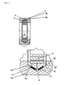
- the invention is thus an attenuating pedestal bearing (4) in the essentially from a pillow block molding component (4a) and a pillow block molding component (4b), which together form the bearing housing, each having an outer and a Inside and a cylindrical bore for receiving a shaft (11) leading rolling bearing (2), each inner side having a common mating surface with the other inner side of the other molding and an inclined surface (7a, 7b), so that when joining the two components (4a) and (4b) on their common Passing surface creates a cylindrical cavity, the one through said inclined surfaces (7) the molded parts formed circumferential, annular, at least partially cone-shaped Recess (6) with an inwardly open through said inclined surfaces having defined cone angle, wherein the recess is an annular, circumferential one or more parts comprehensive damping component (5) fitting accommodates, with the rolling bearing located in the cylindrical cavity (2) is connected.
- the subject matter is, in particular, a corresponding pillow block bearing in which the annular A damping component (5) consisting essentially of (i) one or more parts Elastomeric bearing (1) and (ii) an annular, conical, one or more parts comprehensive support member (3), wherein the support member on the cylindrical Cavity facing side to the rolling bearing (2) is connected or this fixed encloses, and the elastomeric bearing (1) on the rolling bearing (2) opposite Side of the support member (3) is mounted and with the conical recess of the Molded parts (4a), (4b) is in contact
- the carrier part (3) consists of two of the same mutually separate ring parts (3a, 3b), each having one of the inclined surfaces, which form the cone angle of the recess (6). This embodiment is especially of interest if the plummer block should have a bias.
- the elastomeric bearing (1) consists of two identical separate elastomeric ring parts (1a), (1b), which are in contact with the respective inclined surfaces of the conical recess of the mold members (4a), (4b).
- the invention further relates to a corresponding pillow block bearing, in which the elastomeric bearing (1), (1a), (1b) is fixedly connected to the limiting components (3a), (3b), (4a), (4b).
- the invention further relates to a corresponding pillow block, in which the Elastomeric bearing (1), (1a), (1b) comprises at least one elastomeric layer.
- the elastomeric bearing (1), (1a), (1b) has two or more elastomeric layers which are separated by hard layers.
- the invention is preferably a corresponding pillow block, in which the Rolling is not gimbal mobile.
- the elastomeric bearing (1) by itself has a cardanic mobility and thus the always occurring Nick and yaw movements of the rotor shaft is able to absorb what otherwise only the in the prior art used for these purposes more complex and above all Wear more susceptible spherical roller bearings are able to afford.
- the rolling bearing may be rigid or not be adjustable in angle and, for example, in the form of a thrust bearing, a Four-point bearing or preferably a tapered roller or cylindrical roller bearing available.
- Such a bearing according to the invention is also suitable, all of the Wind turbine transferred to absorb rotor forces (moment bearing).
- the invention further relates to a corresponding pillow block, in which the individual presetting of the damping properties of the pillow block the Molded parts (4a), (4b) and the support part (3) of the damping component (5) Clamping means are braced against each other.
- the invention is ultimately the use of a corresponding pillow block for the decoupling of vibration forces, preferably sound vibrations, which be exerted on the rotor shaft of wind turbines.
- Fig. 1 Arrangement of a wind turbine according to the prior art (Schematic Overview), (4) represents the position of the pillow block again.
- Fig. 2 Section through pillow block according to the invention (3D illustration)
- Fig. 3 Schematic sections through inventive pillow block
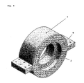
- Fig. 4 3D representation of the entire closed pillow block bearing with mounting flanges according to the invention
- the pillow block (4) comprises two mold components (4a, 4b), which the Form bearing housing.
- they may have attachment means, such as e.g. flanges (10), which make it possible to the pillow block with the machine carrier (12) firmly connect.
- attachment means such as e.g. flanges (10)
- the latter can also be achieved without such means, if one of the Molded parts is an integral part of the machine frame itself.
- the two mold parts (4a), (4b) are correspondingly shaped so that they can form the bearing housing, with a cylindrical bore, preferably in the diameter of the roller bearing to be used, which has a cylindrical diameter corresponding circumferential annular, at least partially conical recess (cone space) having.
- the resulting cone space is thereby inclined surfaces of the mold components. (4a), (4b) of the plummer block housing (4).
- the damping member (5) takes place, in such a way that the elastomeric bearing (1) as a part of the damping part, the surfaces of the annular cone space largely completely or partially fills at least space for pressed elastomeric material must remain free.
- the damping part (5) may possibly only from the one or more parts exist existing elastomeric bearing (1), but preferably it also has an off one or more parts existing solid support part (3), which consists of hard inflexible materials, preferably metal, hard plastics or carbon fiber-containing Fabric is shaped and thus is particularly suitable in the cylindrical cavity to wear and aligned longitudinally to this bearing (2) or to enclose, with which it is firmly connected.
- existing solid support part (3) which consists of hard inflexible materials, preferably metal, hard plastics or carbon fiber-containing Fabric is shaped and thus is particularly suitable in the cylindrical cavity to wear and aligned longitudinally to this bearing (2) or to enclose, with which it is firmly connected.
- the fixed support member (3) preferably consists of two similarly shaped ring members (3a), (3b), each having in principle a cross section in the form of a right triangle or part thereof so as to fit into the conical recess (6) can be, wherein the right angle of each element (3a), (3b) extends in the vertical direction approximately along the apex line of the cone of the circumferential recess and in the horizontal direction approximately along the inner surface of the cylindrical cavity of the pillow block.
- the two carrier parts (3a, 3b) are thus directly opposite to each other along the cone vertex line without being firmly connected to one another. As a result, they are able to adjust or position themselves differently on different stresses or forces. This is particularly important if the pillow block in its preferred embodiment fastening means, preferably clamping screws, which allow a clamping of the housing parts (4a, 4b) with the damping element (5) or preferably the support elements (3a, 3b).
- the elastomeric bearing (1) may be a single workpiece, which in the conical surfaces the recess (6) inserted and with these preferably by gluing or Vulkan matters is firmly connected. Preferably, however, it consists of two elastomeric circumferential layers (1a), (1b), separated on the respective inclined surfaces (7a, 7b) as described, are attached. To save material, the circumferential elastomer layers also be interrupted.
- the elastomeric bearings (1, 1a, 1b) which are used according to the invention are per se are known and consist essentially of one or more elastomer layers, which, in the case of several layers, by inelastic, non-elastomeric, solid, or hard intermediate layers are separated from each other.
- the invention used elastomeric materials consist essentially of a natural rubber, a natural rubber derivative or a suitable elastic polymer Plastic or plastic mixture.
- the elastomer layer can according to the invention different hardness ("Shore hardness") and different damping properties have, according to the desired requirements.
- the preparation of such elastomers of different hardness is in the state of Technique known and adequately described in the relevant literature. Commercially available natural rubbers or plastics are preferably used.
- the non-elastomeric intermediate layers according to the invention are as far as possible made of inelastic materials with low compressibility.
- this metal sheets but also other materials, such as hard plastics, Composite materials or carbon fiber-containing materials can be used.
- the Intermediate sheets and the elastomeric materials are usually made by vulcanization connected with each other.
- the elastomeric bearings (1, 1a, 1b) consist of one to eight, preferably one to three elastomeric layers and are used in a flat design. But it is also possible according to the invention to use concave or convex curved elastomeric bearings, which have the advantage that they are less susceptible to wear. In these cases, it is also necessary to form the conical surfaces of the components (3a, 3b) and (4a, 4b) in the corresponding suitable shape.
- the damping or vibration decoupling takes place according to the invention in that the rolling bearing (2) occurring, caused by the rotating shaft vibration forces directly or preferably via the fixed support member (3) on the actual elastomeric bearing (1) and thus be damped. Due to the selected design features, excellent results can be achieved in particular in the sound decoupling in wind turbines.
Landscapes
- Engineering & Computer Science (AREA)
- General Engineering & Computer Science (AREA)
- Mechanical Engineering (AREA)
- Life Sciences & Earth Sciences (AREA)
- Sustainable Development (AREA)
- Sustainable Energy (AREA)
- Chemical & Material Sciences (AREA)
- Combustion & Propulsion (AREA)
- Support Of The Bearing (AREA)
- Wind Motors (AREA)
Abstract
Description
Gegenstand der Erfindung ist ferner ein entsprechendes Stehlager, bei welchem das Elastomerlager (1), (1a), (1b) fest mit den es begrenzenden Bauteilen (3a), (3b), (4a), (4b) verbunden ist.
| (1) (1a) (1b) | Elastomerlager(teile) |
| (2) | Wälzlager (symbolische Darstellung) |
| (3) (3a) (3b) | Trägerteil(e) des Dämpfungsbauteils (5) |
| (4) (4a) (4b) | gesamtes Stehlager und Stehlager-Formbauteile |
| (5) | Dämpfungsbauteil, bestehend aus Hartbauteil(3) und Elastomerbauteil (1) |
| (6) | Konusraum, bzw. konusförmige Aussparung |
| (7) (7a) (7b) | Konusflächen |
| (8) | Rotorblatt |
| (9) | Getriebe |
| (10) | Befestigungsflansch |
| (11) | Rotorwelle |
| 12 | Maschinenträger |
| Fig. 1 | Anordnung einer Windkraftanlage nach dem Stand der Technik (Schematische Übersicht), (4) gibt die Position des Stehlagers wieder. |
| Fig. 2 | Schnitt durch erfindungsgemäßes Stehlager (3D-Darstellung) |
| Fig. 3 | Schematische Schnitte durch erfindungsgemäßes Stehlager |
| Fig. 4 | 3D-Darstellung des gesamten geschlossenen Stehlagers mit Befestigungsflanschen gemäß der Erfindung |
In diesen kanalähnlichen Konusraum, der zum zylindrischen Hohlraum hin offen ist, findet das Dämpfungsteil (5) Platz, und zwar in der Weise, dass das Elastomerlager (1) als ein Bestandteil des Dämpfungsteils die Flächen des ringförmigen Konusraumes weitgehend vollständig oder teilweise ausfüllt, wobei zumindest Platz für verpresstes Elastomermaterial frei bleiben muss.
Die beiden Trägerteile(3a,3b) liegen sich somit entlang der Konusscheitellinie unmittelbar gegenüber ohne fest miteinander verbunden zu sein. Hierdurch vermögen sie, sich auf unterschiedliche Spannungen bzw. Kräfte unterschiedlich einzustellen, bzw. zu positionieren. Dies ist insbesondere dann von Bedeutung, wenn das Stehlager in seiner bevorzugten Ausführungsform Befestigungsmittel, vorzugsweise Spannschrauben, aufweist, welche eine Verspannung der Gehäuseteile (4a, 4b) mit dem Dämpfungselement (5) oder vorzugsweise den Trägerelementen (3a, 3b) ermöglichen.
Die Dämpfung bzw. Schwingungsentkopplung erfolgt erfindungsgemäß dadurch, dass die im Wälzlager (2) auftretenden, durch die drehende Welle bedingten Schwingungskräfte direkt oder vorzugsweise über das feste Trägerteil (3) auf das eigentliche Elastomerlager (1) weitergeleitet und somit gedämpft werden. Durch die gewählten konstruktiven Merkmale, können so hervorragend Ergebnisse insbesondere bei der Schallentkopplung bei Windkraftanlagen erzielt werden.
- gute Geräuschreduzierung (Schallentkopplung)
- generelle Dämpfung anderweitiger im System auftretender Schwingungen
- Winkeleinstellbarkeit kann durch Einstellbarkeit der Dämpfungseinheit (5) des Elastomerlagers erreicht werden und nicht durch das Wälzlager selbst
- Möglichkeit das Lagergehäuse im Maschinenträger zu integrieren.
Claims (10)
- Dämpfungsfähiges Stehlager (4) im wesentlichen bestehend aus einem Stehlager-Formbauteil (4a) und einem Stehlager-Formbauteil (4b), welche zusammen das Lagergehäuse bilden, mit jeweils einer Außen- und einen Innenseite und einer zylindrischen Bohrung zur Aufnahme eines eine Welle (11) führenden Wälzlagers (2), wobei jede Innenseite eine gemeinsame Passfläche mit der anderen Innenseite des anderen Formteils sowie eine schräge Fläche (7a,7b) aufweist, so dass bei Zusammenfügung der beiden Bauteile (4a) und (4b) über ihre gemeinsame Passfläche ein zylindrischer Hohlraum entsteht, der eine durch besagte schräge Flächen der Formteile gebildete umlaufende, ringförmige, zumindest teilweise konusförmige Aussparung (6) mit einem nach innen geöffneten durch besagte schräge Flächen definierten Konuswinkel aufweist, wobei die Aussparung ein ringförmiges, umlaufendes ein oder mehrere Teile umfassendes Dämpfungsbauteil (5) passend aufnimmt, das mit dem im zylindrische Hohlraum befindlichen Wälzlager (2) verbunden ist.
- Stehlager nach Anspruch 1, dadurch gekennzeichnet, dass das ringförmige Dämpfungsbauteil (5) im wesentlichen aus (i) einem ein oder mehrere Teile umfassendes Elastomerlager (1) und (ii) einem ringförmigen, konusförmigen, ein oder mehrere Teile umfassendes Trägerteil (3) besteht, wobei das Trägerteil auf der dem zylindrischen Hohlraum zugewandten Seite mit dem Wälzlager (2) verbunden ist oder dieses fest umschließt, und das Elastomerlager (1) auf der dem Wälzlager (2) gegenüberliegenden Seite des Trägerteils (3) angebracht ist und mit der konusförmigen Aussparung der Formbauteile (4a), (4b) in Kontakt steht.
- Stehlager nach Anspruch 2, dadurch gekennzeichnet, dass das Trägerteil (3) aus zwei gleichen von einander getrennten Ringteilen (3a, 3b) besteht, die jeweils eine der schrägen Flächen aufweisen, welche den Konuswinkel der Aussparung (6) bilden.
- Stehlager nach Anspruch 2 oder 3, dadurch gekennzeichnet, dass das Elastomerlager (1), aus zwei gleichen voneinander getrennten elastomeren Ringteilen (1a), (1b) besteht, die in Kontakt zu den jeweiligen schrägen Flächen der konusförmigen Aussparung der Formbauteile (4a), (4b) stehen.
- Stehlager nach einem der Ansprüche 2 - 4, dadurch gekennzeichnet, dass das Elastomerlager (1), (1a), (1b) fest mit den es begrenzenden Bauteilen (3a), (3b), (4a), (4b) verbunden ist.
- Stehlager nach einem der Ansprüche 2 - 5, dadurch gekennzeichnet dass das Elastomerlager (1), (1a), (1b) aus mindestens eine elastomere Schicht aufweist.
- Stehlager nach Anspruch 6, dadurch gekennzeichnet, dass Elastomerlager (1), (1a), (1b) zwei oder mehr ealstomere Schichten aufweist, die durch Hartschichten voneinander getrennt sind.
- Stehlager nach einem der Ansprüche 1 - 7, dadurch gekennzeichnet, dass das Wälzlager nicht winkeleinstellbar ist.
- Stehlager nach einem der Ansprüche 1 - 8, dadurch gekennzeichnet, dass zur individuellen Voreinstellung der Dämpfungseigenschaften des Stehlagers die Formbauteile (4a), (4b) und das Trägerteil (3) des Dämpfungsbauteils (5) durch Spannmittel gegeneinander verspannt sind.
- Verwendung eines Stehlagers nach einem oder mehreren der Ansprüche 1 - 9 zur Entkopplung von Schwingungskräften inklusive Schall, welche auf die Rotorwelle von Windkraftanlagen ausgeübt werden.
Priority Applications (1)
| Application Number | Priority Date | Filing Date | Title |
|---|---|---|---|
| EP05002470.2A EP1564406B1 (de) | 2004-02-11 | 2005-02-05 | Dämpfungsfähiges Stehlager für Windkraftanlagen |
Applications Claiming Priority (3)
| Application Number | Priority Date | Filing Date | Title |
|---|---|---|---|
| EP04002989 | 2004-02-11 | ||
| EP04002989 | 2004-02-11 | ||
| EP05002470.2A EP1564406B1 (de) | 2004-02-11 | 2005-02-05 | Dämpfungsfähiges Stehlager für Windkraftanlagen |
Publications (3)
| Publication Number | Publication Date |
|---|---|
| EP1564406A2 true EP1564406A2 (de) | 2005-08-17 |
| EP1564406A3 EP1564406A3 (de) | 2010-08-04 |
| EP1564406B1 EP1564406B1 (de) | 2016-06-22 |
Family
ID=34702377
Family Applications (1)
| Application Number | Title | Priority Date | Filing Date |
|---|---|---|---|
| EP05002470.2A Expired - Lifetime EP1564406B1 (de) | 2004-02-11 | 2005-02-05 | Dämpfungsfähiges Stehlager für Windkraftanlagen |
Country Status (1)
| Country | Link |
|---|---|
| EP (1) | EP1564406B1 (de) |
Cited By (13)
| Publication number | Priority date | Publication date | Assignee | Title |
|---|---|---|---|---|
| DE102006037890A1 (de) * | 2006-08-11 | 2008-02-28 | Ab Skf | Lagerung einer Welle |
| CN101963188A (zh) * | 2010-08-26 | 2011-02-02 | 大连三环复合材料技术开发有限公司 | 风电机组主轴三向组合自润滑滑动轴承 |
| CN102269135A (zh) * | 2011-06-30 | 2011-12-07 | 国电联合动力技术有限公司 | 一种兆瓦级风电增速箱自适应支撑装置 |
| CN102953931A (zh) * | 2011-08-25 | 2013-03-06 | 通用电气公司 | 在风力发电机中调整轴的弯矩的系统和方法 |
| DE102007058165B4 (de) * | 2007-11-30 | 2013-06-13 | Ab Skf | Wälzlagerung |
| CN110925299A (zh) * | 2019-12-23 | 2020-03-27 | 河南澈蓝环保技术有限公司 | 柔性自平衡降噪轴承 |
| AT521885A1 (de) * | 2018-12-13 | 2020-06-15 | Miba Gleitlager Austria Gmbh | Gondel für eine Windkraftanlage |
| CN113167324A (zh) * | 2018-12-13 | 2021-07-23 | 米巴滑动轴承奥地利有限公司 | 用于风力发电设备的机舱 |
| US11761429B2 (en) | 2018-12-13 | 2023-09-19 | Miba Gleitlager Austria Gmbh | Slide bearing, in particular for a gearbox of a wind turbine |
| US11808247B2 (en) | 2018-12-13 | 2023-11-07 | Miba Gleitlager Austria Gmbh | Planetary gear set for a wind turbine |
| WO2023222319A1 (de) * | 2022-05-17 | 2023-11-23 | Zf Friedrichshafen Ag | Federnd gelagertes getriebegehäuse ii |
| US11940006B2 (en) | 2018-12-13 | 2024-03-26 | Miba Gleitlager Austria Gmbh | Method for changing a sliding bearing element of a rotor bearing of a wind turbine, and nacelle for a wind turbine |
| US12110874B2 (en) | 2018-12-13 | 2024-10-08 | Miba Gleitlager Austria Gmbh | Nacelle for a wind turbine |
Family Cites Families (6)
| Publication number | Priority date | Publication date | Assignee | Title |
|---|---|---|---|---|
| US2282589A (en) | 1941-07-12 | 1942-05-12 | Goodrich Co B F | Wheel structure |
| US3554619A (en) | 1968-11-22 | 1971-01-12 | Trw Inc | Bearing support |
| DE19708553C2 (de) | 1997-03-04 | 2000-09-21 | Gmt Gummi Metall Technik Gmbh | Gummigefedertes Schienenrad |
| DE19930751A1 (de) | 1999-07-02 | 2001-01-04 | Franz Mitsch | Verfahren zur Reduzierung von Schwingungen in Windkraftanlagen |
| ATE305101T1 (de) | 2000-10-14 | 2005-10-15 | Franz Mitsch | Getriebelagerung für windkraftanlagen |
| DE10310639A1 (de) | 2003-03-10 | 2004-09-23 | Volker Limbeck | Abtriebskonfiguration für Windenergieanlagen |
-
2005
- 2005-02-05 EP EP05002470.2A patent/EP1564406B1/de not_active Expired - Lifetime
Cited By (22)
| Publication number | Priority date | Publication date | Assignee | Title |
|---|---|---|---|---|
| DE102006037890A1 (de) * | 2006-08-11 | 2008-02-28 | Ab Skf | Lagerung einer Welle |
| DE102006037890B4 (de) * | 2006-08-11 | 2010-04-08 | Ab Skf | Lagerung einer Welle |
| DE102007058165B4 (de) * | 2007-11-30 | 2013-06-13 | Ab Skf | Wälzlagerung |
| CN101963188A (zh) * | 2010-08-26 | 2011-02-02 | 大连三环复合材料技术开发有限公司 | 风电机组主轴三向组合自润滑滑动轴承 |
| CN102269135A (zh) * | 2011-06-30 | 2011-12-07 | 国电联合动力技术有限公司 | 一种兆瓦级风电增速箱自适应支撑装置 |
| CN102269135B (zh) * | 2011-06-30 | 2013-01-09 | 国电联合动力技术有限公司 | 一种兆瓦级风电增速箱自适应支撑装置 |
| CN102953931A (zh) * | 2011-08-25 | 2013-03-06 | 通用电气公司 | 在风力发电机中调整轴的弯矩的系统和方法 |
| CN102953931B (zh) * | 2011-08-25 | 2015-11-18 | 通用电气公司 | 在风力发电机中调整轴的弯矩的系统和方法 |
| AT521885B1 (de) * | 2018-12-13 | 2020-09-15 | Miba Gleitlager Austria Gmbh | Gondel für eine Windkraftanlage |
| US11761429B2 (en) | 2018-12-13 | 2023-09-19 | Miba Gleitlager Austria Gmbh | Slide bearing, in particular for a gearbox of a wind turbine |
| US12196184B2 (en) | 2018-12-13 | 2025-01-14 | Miba Gleitlager Austria Gmbh | Nacelle for a wind turbine |
| CN113167324A (zh) * | 2018-12-13 | 2021-07-23 | 米巴滑动轴承奥地利有限公司 | 用于风力发电设备的机舱 |
| CN113167316A (zh) * | 2018-12-13 | 2021-07-23 | 米巴滑动轴承奥地利有限公司 | 用于风力设备的吊舱 |
| CN113167316B (zh) * | 2018-12-13 | 2022-12-16 | 米巴滑动轴承奥地利有限公司 | 用于风力设备的吊舱 |
| US11746757B2 (en) | 2018-12-13 | 2023-09-05 | Miba Gleitlager Austria Gmbh | Nacelle for a wind turbine |
| AT521885A1 (de) * | 2018-12-13 | 2020-06-15 | Miba Gleitlager Austria Gmbh | Gondel für eine Windkraftanlage |
| US11808247B2 (en) | 2018-12-13 | 2023-11-07 | Miba Gleitlager Austria Gmbh | Planetary gear set for a wind turbine |
| US12110874B2 (en) | 2018-12-13 | 2024-10-08 | Miba Gleitlager Austria Gmbh | Nacelle for a wind turbine |
| US11940006B2 (en) | 2018-12-13 | 2024-03-26 | Miba Gleitlager Austria Gmbh | Method for changing a sliding bearing element of a rotor bearing of a wind turbine, and nacelle for a wind turbine |
| CN110925299A (zh) * | 2019-12-23 | 2020-03-27 | 河南澈蓝环保技术有限公司 | 柔性自平衡降噪轴承 |
| WO2023222319A1 (de) * | 2022-05-17 | 2023-11-23 | Zf Friedrichshafen Ag | Federnd gelagertes getriebegehäuse ii |
| US12553414B2 (en) | 2022-05-17 | 2026-02-17 | Zf Friedrichshafen Ag | Spring-mounted gearbox housing |
Also Published As
| Publication number | Publication date |
|---|---|
| EP1564406A3 (de) | 2010-08-04 |
| EP1564406B1 (de) | 2016-06-22 |
Similar Documents
| Publication | Publication Date | Title |
|---|---|---|
| EP2895768B1 (de) | Elastisches pendellager | |
| EP2352930B1 (de) | Unsymmetrische lagerung | |
| EP2003362B1 (de) | Hydraulisch vorgespanntes elastomeres Federelement und seine Verwendung in Lagern von Windkraftanlagen | |
| EP1564406B1 (de) | Dämpfungsfähiges Stehlager für Windkraftanlagen | |
| EP1566543B1 (de) | Elastomerlagerung mit regulierbarer Steifigkeit | |
| EP1046832B1 (de) | Spannbuchse und ihre Verwendung in Windkraftanlagen | |
| DE102012205086A1 (de) | Getriebelagerung einer Windenergieanlage, Windenergieanlage und Verfahren zum Warten einer Getriebelagerung | |
| EP2831413B1 (de) | Windenergieanlage mit getriebelagerung und verfahren zum warten der getriebelagerung | |
| EP2882962B1 (de) | Rotorwelle für eine windturbine | |
| EP3420227A1 (de) | Windkraftanlagen mit elastischen kugel-pendellagern | |
| EP3012479A1 (de) | Elastisches mehrkantenlager für windkraftanlagen | |
| EP1197677B1 (de) | Getriebelagerung für Windkraftanlagen | |
| EP3899266A1 (de) | Impuls-schwingungstilger für hohe schlanke strukturen | |
| EP2059673B1 (de) | Windenergieanlage | |
| EP3121443A1 (de) | Triebstranglagerung einer windenergieanlage und windenergieanlage | |
| EP2821665B1 (de) | Kombilager zur Dämpfung axialer und radialer Schwingungen | |
| WO2009094998A2 (de) | Wassergeschmierte lageranordnung | |
| EP2740933B1 (de) | Windenergieanlage | |
| DE102006037890A1 (de) | Lagerung einer Welle | |
| CH711738A1 (de) | Rotorblattkopplungsvorrichtung zur Kopplung mit einem Rotormast zur Bildung eines Rotorkopfs eines Drehflüglers. | |
| WO2023006703A1 (de) | Lagerbuchse, lagerbuchsenanordnung und windenergieanlagenlager für windenergieanlagen | |
| DE102011053015A1 (de) | Zylindrische Halbschale für eine radial verspannbare Lagerbuchse | |
| EP1593867A1 (de) | Kupplung mit vorgespannten Lagerelementen | |
| EP2740934B1 (de) | Windenergieanlage | |
| EP2740932B1 (de) | Windenergieanlage |
Legal Events
| Date | Code | Title | Description |
|---|---|---|---|
| PUAI | Public reference made under article 153(3) epc to a published international application that has entered the european phase |
Free format text: ORIGINAL CODE: 0009012 |
|
| AK | Designated contracting states |
Kind code of ref document: A2 Designated state(s): AT BE BG CH CY CZ DE DK EE ES FI FR GB GR HU IE IS IT LI LT LU MC NL PL PT RO SE SI SK TR |
|
| AX | Request for extension of the european patent |
Extension state: AL BA HR LV MK YU |
|
| PUAL | Search report despatched |
Free format text: ORIGINAL CODE: 0009013 |
|
| AK | Designated contracting states |
Kind code of ref document: A3 Designated state(s): AT BE BG CH CY CZ DE DK EE ES FI FR GB GR HU IE IS IT LI LT LU MC NL PL PT RO SE SI SK TR |
|
| AX | Request for extension of the european patent |
Extension state: AL BA HR LV MK YU |
|
| RIC1 | Information provided on ipc code assigned before grant |
Ipc: F03D 11/00 20060101AFI20050428BHEP Ipc: F16C 23/08 20060101ALI20100701BHEP |
|
| 17P | Request for examination filed |
Effective date: 20110126 |
|
| AKX | Designation fees paid |
Designated state(s): AT BE BG CH CY LI |
|
| RBV | Designated contracting states (corrected) |
Designated state(s): AT BE BG CH CY CZ DE DK EE ES FI FR GB GR HU IE IS IT LI LT LU MC NL PL PT RO SE SI SK TR |
|
| REG | Reference to a national code |
Ref country code: DE Ref legal event code: 8566 Ref country code: DE Ref legal event code: R108 Effective date: 20110315 |
|
| 17Q | First examination report despatched |
Effective date: 20110705 |
|
| GRAP | Despatch of communication of intention to grant a patent |
Free format text: ORIGINAL CODE: EPIDOSNIGR1 |
|
| REG | Reference to a national code |
Ref country code: DE Ref legal event code: R079 Ref document number: 502005015255 Country of ref document: DE Free format text: PREVIOUS MAIN CLASS: F03D0011000000 Ipc: F03D0080000000 |
|
| INTG | Intention to grant announced |
Effective date: 20160114 |
|
| RIC1 | Information provided on ipc code assigned before grant |
Ipc: F16C 23/08 20060101ALI20160113BHEP Ipc: F03D 80/00 20160101AFI20160113BHEP |
|
| RAP1 | Party data changed (applicant data changed or rights of an application transferred) |
Owner name: FM ENERGIE GMBH & CO. KG |
|
| RIN1 | Information on inventor provided before grant (corrected) |
Inventor name: MITSCH, FRANZ |
|
| GRAS | Grant fee paid |
Free format text: ORIGINAL CODE: EPIDOSNIGR3 |
|
| GRAA | (expected) grant |
Free format text: ORIGINAL CODE: 0009210 |
|
| AK | Designated contracting states |
Kind code of ref document: B1 Designated state(s): AT BE BG CH CY CZ DE DK EE ES FI FR GB GR HU IE IS IT LI LT LU MC NL PL PT RO SE SI SK TR |
|
| REG | Reference to a national code |
Ref country code: GB Ref legal event code: FG4D Free format text: NOT ENGLISH |
|
| REG | Reference to a national code |
Ref country code: CH Ref legal event code: EP |
|
| REG | Reference to a national code |
Ref country code: IE Ref legal event code: FG4D Free format text: LANGUAGE OF EP DOCUMENT: GERMAN |
|
| REG | Reference to a national code |
Ref country code: AT Ref legal event code: REF Ref document number: 807825 Country of ref document: AT Kind code of ref document: T Effective date: 20160715 |
|
| REG | Reference to a national code |
Ref country code: DE Ref legal event code: R096 Ref document number: 502005015255 Country of ref document: DE |
|
| REG | Reference to a national code |
Ref country code: CH Ref legal event code: NV Representative=s name: BOVARD AG, CH |
|
| REG | Reference to a national code |
Ref country code: DK Ref legal event code: T3 Effective date: 20160912 |
|
| REG | Reference to a national code |
Ref country code: NL Ref legal event code: FP |
|
| REG | Reference to a national code |
Ref country code: LT Ref legal event code: MG4D |
|
| PG25 | Lapsed in a contracting state [announced via postgrant information from national office to epo] |
Ref country code: LT Free format text: LAPSE BECAUSE OF FAILURE TO SUBMIT A TRANSLATION OF THE DESCRIPTION OR TO PAY THE FEE WITHIN THE PRESCRIBED TIME-LIMIT Effective date: 20160622 |
|
| REG | Reference to a national code |
Ref country code: ES Ref legal event code: FG2A Ref document number: 2590533 Country of ref document: ES Kind code of ref document: T3 Effective date: 20161122 |
|
| PG25 | Lapsed in a contracting state [announced via postgrant information from national office to epo] |
Ref country code: GR Free format text: LAPSE BECAUSE OF FAILURE TO SUBMIT A TRANSLATION OF THE DESCRIPTION OR TO PAY THE FEE WITHIN THE PRESCRIBED TIME-LIMIT Effective date: 20160923 Ref country code: SE Free format text: LAPSE BECAUSE OF FAILURE TO SUBMIT A TRANSLATION OF THE DESCRIPTION OR TO PAY THE FEE WITHIN THE PRESCRIBED TIME-LIMIT Effective date: 20160622 |
|
| PG25 | Lapsed in a contracting state [announced via postgrant information from national office to epo] |
Ref country code: SK Free format text: LAPSE BECAUSE OF FAILURE TO SUBMIT A TRANSLATION OF THE DESCRIPTION OR TO PAY THE FEE WITHIN THE PRESCRIBED TIME-LIMIT Effective date: 20160622 Ref country code: EE Free format text: LAPSE BECAUSE OF FAILURE TO SUBMIT A TRANSLATION OF THE DESCRIPTION OR TO PAY THE FEE WITHIN THE PRESCRIBED TIME-LIMIT Effective date: 20160622 Ref country code: CZ Free format text: LAPSE BECAUSE OF FAILURE TO SUBMIT A TRANSLATION OF THE DESCRIPTION OR TO PAY THE FEE WITHIN THE PRESCRIBED TIME-LIMIT Effective date: 20160622 Ref country code: IS Free format text: LAPSE BECAUSE OF FAILURE TO SUBMIT A TRANSLATION OF THE DESCRIPTION OR TO PAY THE FEE WITHIN THE PRESCRIBED TIME-LIMIT Effective date: 20161022 Ref country code: RO Free format text: LAPSE BECAUSE OF FAILURE TO SUBMIT A TRANSLATION OF THE DESCRIPTION OR TO PAY THE FEE WITHIN THE PRESCRIBED TIME-LIMIT Effective date: 20160622 |
|
| REG | Reference to a national code |
Ref country code: FR Ref legal event code: PLFP Year of fee payment: 13 |
|
| PG25 | Lapsed in a contracting state [announced via postgrant information from national office to epo] |
Ref country code: PT Free format text: LAPSE BECAUSE OF FAILURE TO SUBMIT A TRANSLATION OF THE DESCRIPTION OR TO PAY THE FEE WITHIN THE PRESCRIBED TIME-LIMIT Effective date: 20161024 |
|
| REG | Reference to a national code |
Ref country code: DE Ref legal event code: R026 Ref document number: 502005015255 Country of ref document: DE |
|
| PLBI | Opposition filed |
Free format text: ORIGINAL CODE: 0009260 |
|
| PLAX | Notice of opposition and request to file observation + time limit sent |
Free format text: ORIGINAL CODE: EPIDOSNOBS2 |
|
| 26 | Opposition filed |
Opponent name: GMT GUMMI-METALL-TECHNIK GMBH Effective date: 20170322 |
|
| PLAB | Opposition data, opponent's data or that of the opponent's representative modified |
Free format text: ORIGINAL CODE: 0009299OPPO |
|
| R26 | Opposition filed (corrected) |
Opponent name: GMT GUMMI-METALL-TECHNIK GMBH Effective date: 20170322 |
|
| PG25 | Lapsed in a contracting state [announced via postgrant information from national office to epo] |
Ref country code: SI Free format text: LAPSE BECAUSE OF FAILURE TO SUBMIT A TRANSLATION OF THE DESCRIPTION OR TO PAY THE FEE WITHIN THE PRESCRIBED TIME-LIMIT Effective date: 20160622 |
|
| PLBB | Reply of patent proprietor to notice(s) of opposition received |
Free format text: ORIGINAL CODE: EPIDOSNOBS3 |
|
| PG25 | Lapsed in a contracting state [announced via postgrant information from national office to epo] |
Ref country code: MC Free format text: LAPSE BECAUSE OF FAILURE TO SUBMIT A TRANSLATION OF THE DESCRIPTION OR TO PAY THE FEE WITHIN THE PRESCRIBED TIME-LIMIT Effective date: 20160622 |
|
| REG | Reference to a national code |
Ref country code: IE Ref legal event code: MM4A |
|
| PG25 | Lapsed in a contracting state [announced via postgrant information from national office to epo] |
Ref country code: LU Free format text: LAPSE BECAUSE OF NON-PAYMENT OF DUE FEES Effective date: 20170205 |
|
| REG | Reference to a national code |
Ref country code: FR Ref legal event code: PLFP Year of fee payment: 14 |
|
| PG25 | Lapsed in a contracting state [announced via postgrant information from national office to epo] |
Ref country code: IE Free format text: LAPSE BECAUSE OF NON-PAYMENT OF DUE FEES Effective date: 20170205 |
|
| PLAG | Information modified related to despatch of communication that opposition is rejected |
Free format text: ORIGINAL CODE: EPIDOSCREJ1 |
|
| RDAE | Information deleted related to despatch of communication that patent is revoked |
Free format text: ORIGINAL CODE: EPIDOSDREV1 |
|
| RDAF | Communication despatched that patent is revoked |
Free format text: ORIGINAL CODE: EPIDOSNREV1 |
|
| PLCK | Communication despatched that opposition was rejected |
Free format text: ORIGINAL CODE: EPIDOSNREJ1 |
|
| REG | Reference to a national code |
Ref country code: DE Ref legal event code: R100 Ref document number: 502005015255 Country of ref document: DE |
|
| PLBN | Opposition rejected |
Free format text: ORIGINAL CODE: 0009273 |
|
| STAA | Information on the status of an ep patent application or granted ep patent |
Free format text: STATUS: OPPOSITION REJECTED |
|
| 27O | Opposition rejected |
Effective date: 20181101 |
|
| RDAF | Communication despatched that patent is revoked |
Free format text: ORIGINAL CODE: EPIDOSNREV1 |
|
| RDAE | Information deleted related to despatch of communication that patent is revoked |
Free format text: ORIGINAL CODE: EPIDOSDREV1 |
|
| PGFP | Annual fee paid to national office [announced via postgrant information from national office to epo] |
Ref country code: NO Payment date: 20190211 Year of fee payment: 8 Ref country code: FI Payment date: 20190219 Year of fee payment: 15 |
|
| PG25 | Lapsed in a contracting state [announced via postgrant information from national office to epo] |
Ref country code: HU Free format text: LAPSE BECAUSE OF FAILURE TO SUBMIT A TRANSLATION OF THE DESCRIPTION OR TO PAY THE FEE WITHIN THE PRESCRIBED TIME-LIMIT; INVALID AB INITIO Effective date: 20050205 |
|
| PG25 | Lapsed in a contracting state [announced via postgrant information from national office to epo] |
Ref country code: BG Free format text: LAPSE BECAUSE OF FAILURE TO SUBMIT A TRANSLATION OF THE DESCRIPTION OR TO PAY THE FEE WITHIN THE PRESCRIBED TIME-LIMIT Effective date: 20160622 |
|
| PG25 | Lapsed in a contracting state [announced via postgrant information from national office to epo] |
Ref country code: CY Free format text: LAPSE BECAUSE OF NON-PAYMENT OF DUE FEES Effective date: 20160622 |
|
| PGFP | Annual fee paid to national office [announced via postgrant information from national office to epo] |
Ref country code: NL Payment date: 20200218 Year of fee payment: 16 Ref country code: AT Payment date: 20200302 Year of fee payment: 16 Ref country code: IT Payment date: 20200219 Year of fee payment: 16 |
|
| PGFP | Annual fee paid to national office [announced via postgrant information from national office to epo] |
Ref country code: CH Payment date: 20200212 Year of fee payment: 16 Ref country code: BE Payment date: 20200219 Year of fee payment: 16 |
|
| PGFP | Annual fee paid to national office [announced via postgrant information from national office to epo] |
Ref country code: TR Payment date: 20200117 Year of fee payment: 16 |
|
| REG | Reference to a national code |
Ref country code: FI Ref legal event code: MAE |
|
| PG25 | Lapsed in a contracting state [announced via postgrant information from national office to epo] |
Ref country code: FI Free format text: LAPSE BECAUSE OF NON-PAYMENT OF DUE FEES Effective date: 20200205 |
|
| PGFP | Annual fee paid to national office [announced via postgrant information from national office to epo] |
Ref country code: FR Payment date: 20210211 Year of fee payment: 17 |
|
| PG25 | Lapsed in a contracting state [announced via postgrant information from national office to epo] |
Ref country code: PL Free format text: LAPSE BECAUSE OF NON-PAYMENT OF DUE FEES Effective date: 20200205 |
|
| REG | Reference to a national code |
Ref country code: AT Ref legal event code: MM01 Ref document number: 807825 Country of ref document: AT Kind code of ref document: T Effective date: 20210205 |
|
| REG | Reference to a national code |
Ref country code: BE Ref legal event code: MM Effective date: 20210228 |
|
| PG25 | Lapsed in a contracting state [announced via postgrant information from national office to epo] |
Ref country code: LI Free format text: LAPSE BECAUSE OF NON-PAYMENT OF DUE FEES Effective date: 20210228 Ref country code: CH Free format text: LAPSE BECAUSE OF NON-PAYMENT OF DUE FEES Effective date: 20210228 Ref country code: AT Free format text: LAPSE BECAUSE OF NON-PAYMENT OF DUE FEES Effective date: 20210205 |
|
| REG | Reference to a national code |
Ref country code: NL Ref legal event code: MM Effective date: 20210301 |
|
| PG25 | Lapsed in a contracting state [announced via postgrant information from national office to epo] |
Ref country code: NL Free format text: LAPSE BECAUSE OF NON-PAYMENT OF DUE FEES Effective date: 20210301 |
|
| PG25 | Lapsed in a contracting state [announced via postgrant information from national office to epo] |
Ref country code: IT Free format text: LAPSE BECAUSE OF NON-PAYMENT OF DUE FEES Effective date: 20210205 |
|
| PG25 | Lapsed in a contracting state [announced via postgrant information from national office to epo] |
Ref country code: BE Free format text: LAPSE BECAUSE OF NON-PAYMENT OF DUE FEES Effective date: 20210228 |
|
| PG25 | Lapsed in a contracting state [announced via postgrant information from national office to epo] |
Ref country code: FR Free format text: LAPSE BECAUSE OF NON-PAYMENT OF DUE FEES Effective date: 20220228 |
|
| PGFP | Annual fee paid to national office [announced via postgrant information from national office to epo] |
Ref country code: ES Payment date: 20230301 Year of fee payment: 19 Ref country code: DK Payment date: 20230220 Year of fee payment: 19 |
|
| PGFP | Annual fee paid to national office [announced via postgrant information from national office to epo] |
Ref country code: GB Payment date: 20230105 Year of fee payment: 19 Ref country code: DE Payment date: 20230316 Year of fee payment: 19 |
|
| REG | Reference to a national code |
Ref country code: DE Ref legal event code: R119 Ref document number: 502005015255 Country of ref document: DE |
|
| REG | Reference to a national code |
Ref country code: DK Ref legal event code: EBP Effective date: 20240229 |
|
| PG25 | Lapsed in a contracting state [announced via postgrant information from national office to epo] |
Ref country code: TR Free format text: LAPSE BECAUSE OF NON-PAYMENT OF DUE FEES Effective date: 20210205 |
|
| GBPC | Gb: european patent ceased through non-payment of renewal fee |
Effective date: 20240205 |
|
| PG25 | Lapsed in a contracting state [announced via postgrant information from national office to epo] |
Ref country code: DE Free format text: LAPSE BECAUSE OF NON-PAYMENT OF DUE FEES Effective date: 20240903 |
|
| PG25 | Lapsed in a contracting state [announced via postgrant information from national office to epo] |
Ref country code: DK Free format text: LAPSE BECAUSE OF NON-PAYMENT OF DUE FEES Effective date: 20240229 |
|
| PG25 | Lapsed in a contracting state [announced via postgrant information from national office to epo] |
Ref country code: GB Free format text: LAPSE BECAUSE OF NON-PAYMENT OF DUE FEES Effective date: 20240205 |
|
| PG25 | Lapsed in a contracting state [announced via postgrant information from national office to epo] |
Ref country code: GB Free format text: LAPSE BECAUSE OF NON-PAYMENT OF DUE FEES Effective date: 20240205 Ref country code: DK Free format text: LAPSE BECAUSE OF NON-PAYMENT OF DUE FEES Effective date: 20240229 Ref country code: DE Free format text: LAPSE BECAUSE OF NON-PAYMENT OF DUE FEES Effective date: 20240903 |
|
| REG | Reference to a national code |
Ref country code: ES Ref legal event code: FD2A Effective date: 20250327 |
|
| PG25 | Lapsed in a contracting state [announced via postgrant information from national office to epo] |
Ref country code: ES Free format text: LAPSE BECAUSE OF NON-PAYMENT OF DUE FEES Effective date: 20240206 |