EP1564379A2 - Arrangement for a Turbomachine driven electric generator - Google Patents
Arrangement for a Turbomachine driven electric generator Download PDFInfo
- Publication number
- EP1564379A2 EP1564379A2 EP05250843A EP05250843A EP1564379A2 EP 1564379 A2 EP1564379 A2 EP 1564379A2 EP 05250843 A EP05250843 A EP 05250843A EP 05250843 A EP05250843 A EP 05250843A EP 1564379 A2 EP1564379 A2 EP 1564379A2
- Authority
- EP
- European Patent Office
- Prior art keywords
- bearing
- turbine
- compressor
- arrangement
- module
- Prior art date
- Legal status (The legal status is an assumption and is not a legal conclusion. Google has not performed a legal analysis and makes no representation as to the accuracy of the status listed.)
- Withdrawn
Links
- 238000002485 combustion reaction Methods 0.000 claims abstract description 33
- 238000001816 cooling Methods 0.000 claims abstract description 33
- 238000010276 construction Methods 0.000 claims abstract description 8
- 238000011144 upstream manufacturing Methods 0.000 claims abstract description 3
- 125000006850 spacer group Chemical group 0.000 claims description 26
- 239000000112 cooling gas Substances 0.000 claims description 24
- 239000007789 gas Substances 0.000 claims description 20
- 230000008878 coupling Effects 0.000 claims description 12
- 238000010168 coupling process Methods 0.000 claims description 12
- 238000005859 coupling reaction Methods 0.000 claims description 12
- 239000007788 liquid Substances 0.000 claims description 9
- 239000002826 coolant Substances 0.000 claims description 6
- 238000005096 rolling process Methods 0.000 claims description 5
- 239000000463 material Substances 0.000 claims description 3
- 238000010079 rubber tapping Methods 0.000 claims description 2
- 238000005452 bending Methods 0.000 description 3
- 210000000078 claw Anatomy 0.000 description 3
- 230000008901 benefit Effects 0.000 description 2
- 239000000919 ceramic Substances 0.000 description 2
- 239000000446 fuel Substances 0.000 description 2
- 229910001220 stainless steel Inorganic materials 0.000 description 2
- 239000010935 stainless steel Substances 0.000 description 2
- XLYOFNOQVPJJNP-UHFFFAOYSA-N water Substances O XLYOFNOQVPJJNP-UHFFFAOYSA-N 0.000 description 2
- 230000005540 biological transmission Effects 0.000 description 1
- 238000010586 diagram Methods 0.000 description 1
- 230000000694 effects Effects 0.000 description 1
- 238000010438 heat treatment Methods 0.000 description 1
- 238000007689 inspection Methods 0.000 description 1
- 238000009413 insulation Methods 0.000 description 1
- 239000012212 insulator Substances 0.000 description 1
- 238000005259 measurement Methods 0.000 description 1
- 238000012544 monitoring process Methods 0.000 description 1
Images





Classifications
-
- F—MECHANICAL ENGINEERING; LIGHTING; HEATING; WEAPONS; BLASTING
- F01—MACHINES OR ENGINES IN GENERAL; ENGINE PLANTS IN GENERAL; STEAM ENGINES
- F01D—NON-POSITIVE DISPLACEMENT MACHINES OR ENGINES, e.g. STEAM TURBINES
- F01D25/00—Component parts, details, or accessories, not provided for in, or of interest apart from, other groups
- F01D25/08—Cooling; Heating; Heat-insulation
- F01D25/12—Cooling
-
- F—MECHANICAL ENGINEERING; LIGHTING; HEATING; WEAPONS; BLASTING
- F01—MACHINES OR ENGINES IN GENERAL; ENGINE PLANTS IN GENERAL; STEAM ENGINES
- F01D—NON-POSITIVE DISPLACEMENT MACHINES OR ENGINES, e.g. STEAM TURBINES
- F01D15/00—Adaptations of machines or engines for special use; Combinations of engines with devices driven thereby
- F01D15/10—Adaptations for driving, or combinations with, electric generators
-
- F—MECHANICAL ENGINEERING; LIGHTING; HEATING; WEAPONS; BLASTING
- F01—MACHINES OR ENGINES IN GENERAL; ENGINE PLANTS IN GENERAL; STEAM ENGINES
- F01D—NON-POSITIVE DISPLACEMENT MACHINES OR ENGINES, e.g. STEAM TURBINES
- F01D25/00—Component parts, details, or accessories, not provided for in, or of interest apart from, other groups
- F01D25/16—Arrangement of bearings; Supporting or mounting bearings in casings
Definitions
- the present invention relates to a turbomachinery electric generator arrangement.
- the present invention provides a turbomachinery electric generator arrangement comprising:
- the compressor has a primary compressed gas output for directing air to the combustion chamber and a subsidiary gas output for tapping off cooling gas.
- the subsidiary gas output is upstream of the primary gas outlet.
- the compressed gas for cooling tapped off from the compressor is therefor preferably at a tap off pressure lower than the primary gas output from the compressor directed to the combustion chamber.
- the compressor comprises a radial flow impeller.
- the turbine beneficially comprises a radial inflow, axial outflow, impeller.
- the compressor and the turbine are preferably provided at spaced portions of the arrangement.
- the generator arrangement is preferably provided intermediate the compressor and the turbine. It is preferred that the compressor and the turbine are overhung at opposed ends of the rotor of the arrangement.
- the compressed cooling gas tapped off from the compressor is directed to cool the bearing arrangement.
- the bearing arrangement beneficially comprises a compressor proximal bearing and a turbine proximal bearing, the cooling gas tapped off from the compressor being advantageously directed to cool both the compressor proximal and turbine proximal bearings.
- the cooling gas tapped off from the compressor is directed along a manifold arrangement to cool both the compressor proximal and turbine proximal bearings.
- the manifold arrangement has a branch directing cooling gas to the region of the turbine proximal bearing and a branch directing cooling gas to the region of the compressor proximal bearing.
- the cooling gas tapped off from the compressor may be directed to cool both the compressor proximal and turbine proximal bearings, the cooling gas passing to the turbine proximal bearing prior to passing to the compressor proximal bearing.
- cooling gas tapped off from the compressor is directed along a cooling path, which cooling path includes the space between the generator arrangement armature and stator.
- cooling gas tapped off from the compressor is directed along a cooling path, which cooling path includes a portion internally of the armature of the generator.
- the rotor comprises an internal bore, and cooling gas is directed into and out of the bore.
- the bore includes an insert to guide the cooling gas to wash the internal bore of the rotor.
- the insert is preferably of high resistivity material, such as for example stainless steel.
- the insert may be located in position in the bore of the rotor by a plurality of upstands projecting from the main body of the insert. It is preferred that the insert has a hollow interior.
- the generator arrangement includes a plurality of generators, each generator having a respective rotary armature and a stator, the bearing arrangement including a bearing intermediate the generators.
- the bearing arrangement includes a bearing taking up axial thrust and surge.
- the bearing arrangement preferably includes a tilting pad bearing.
- the bearing arrangement includes a rolling element bearing arrangement.
- the arrangement further includes a shield for thermally protecting a bearing proximate the turbine from the heat of the turbine.
- the shield comprises a liquid cooled element.
- the liquid cooled element beneficially includes an internal liquid coolant flowpath. It is preferred that the coolant flowpath extends inwardly towards the rotational axis of the rotor and subsequently outwardly away from the rotational axis of the rotor.
- the flowpath preferably follows a spiral path.
- the shield is configured as an annular element.
- the shield is mounted between the turbine and the turbine proximate bearing.
- the shield is mounted against the backing plate of the turbine, preferably separated from the backing plate by an air gap.
- the present invention provides a turbomachinery electric generator arrangement comprising:
- the present invention provides a turbomachinery electric generator arrangement of modular construction comprising:
- One or more bearing modules each comprising a bearing spacer module and a bearing housing module, and supporting in rotation the impeller of the compressor, the armature of the generator and the impeller of the turbine.
- the compressor module, the bearing spacer module, the bearing housing module, the generator module and the turbine module have common flanges of the same dimensions whereby they may be bolted one to another in a desired combination and sequence.
- the flange of the bearing housing is preferably sandwiched between respective flanges of the bearing spacer and its adjacent module.
- the rotating members, the impeller of the compressor, the armature of the generator and the impeller of the turbine have common terminals for the transmission of torque and to maintain them coaxial such as is provided by Hirth couplings and axial tie bolts.
- the modules are designed so that they may be assembled in the combination and sequence required by each different application with the least internal adjustment. For instance different power outputs will require internal adjustments of the compressor module and of the turbine module, but their flanging remains unchanged.
- Item 1 of Figure 1A is the centrifugal compressor that supplies compressed air to the combustion chamber or combustion chambers 2 that deliver the products of combustion to the radial inward flow turbine 3.
- the impellers of the compressor and of the turbine are overhung at the ends of the rotor 4, 5, 6 that runs in the bearings 7 and 8 one of which includes a thrust/surge bearing.
- Item 5 is the permanent magnet armature of the high-speed generator
- 9 is the stator of the generator in which current is induced by the rotation of the armature. The current passes to an inverter (not indicated) that converts to the voltage and frequency required by the load, the electrical energy supplied to it from the stator.
- the compressed air from the compressor passes, as is known in the art, to a combustion chamber or chambers where fuel is burnt to form the high temperature products of combustion that are passed to the turbine, and are expanded on passage through the turbine.
- a combustion chamber or chambers where fuel is burnt to form the high temperature products of combustion that are passed to the turbine, and are expanded on passage through the turbine.
- the turbine When running above a threshold speed, its self-sustaining speed, the turbine generates sufficient power to drive the compressor, and at speeds above the self-sustaining speed, and with the necessary increase in the flow of fuel, the turbine generates the additional power that is required as the generator is loaded.
- the turbine is run-up to its self-sustaining speed by using the generator in its motor mode in which it takes electrical energy temporarily, via the inverter, from a battery or other supply.
- FIG. 1B Another arrangement is illustrated diagrammatically in Figure 1B.
- Two generators of the same rating or of different ratings are now close coupled in tandem but, except for such changes in detail as may be required by the increased power demand, the compressor, the turbine and the combustion chamber or combustion chambers remain the same.
- the rotor 4, 5, 10, 5a, 11 runs on the three bearings 7, 12, 13 one of which includes a thrust/surge bearing.
- units are to be assembled from a number of modules standardised in design although they will sometimes differ in their dimensions, and in the instance of the rotors they will have different ends in dependence upon their application.
- the modules of Figure 1B include the lesser number of modules of Figure 1A and it is sufficient to provide diagrammatic illustrations of the modules of Figure 1B.
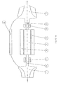
- the modules of Figure 1B are illustrated in Figure 2 in which the central figure illustrates the casings of its modules. (Although the numbering of Figure 2 partly follows that of Figure 1, the designations of the two sets of numbers are not identical.)
- Item 1 of Figure 2 is the compressor module, 2 is the combustion chamber module, 3 is the turbine module, 4 is the generator module, and 6 is the bearing spacer module.
- the armatures of the generator modules are illustrated at 5.
- the modules 1, 6, 4 and 3 are flanged and are illustrated bolted together in the sequence 1, 6, 4, 6, 4, 6, 3.
- combustion chamber module 2 in the figure (the construction of which is well known in the art), the preferred construction of the modules will now be described in detail. However the description will be prefaced by referring to two design problems. The first is the removal of heat from the armature of a rotor. Although ideally no eddy currents are induced in an armature there are harmonics that generate eddy currents present in the field in which the armature rotates. The heat produced by the eddy currents has to be removed. The second is that the bearing module 7 in proximity to the turbine has to be protected from the heat of the turbine.
- FIG. 3 A preferred construction of the compressor module is illustrated in Figure 3 in which 1.1 is the impeller of the compressor, 1.2 is the vaneless space of the principal output of the compressor and 1.3 is its volute.
- the compressor has a subsidiary vaneless space at 1.4 and volute 1.5.
- the vaneless space is bridged (not illustrated) at three or more points near its outer periphery to hold the outer part of the compressor casing rigid by to its principal member.
- the purpose of this secondary provision is to tap a supply of air at the lower pressure required for the cooling, noted above, of the armatures. (it is inefficient to draw the cooling air from the higher pressure of the principal output, as the greater work required producing that air is wasted, and becomes unwanted heat on throttling to the pressure required for cooling.)
- the flexible panel 1.6 closes the secondary volute and carries the outlet 1.10 of the lower pressure air. The panel is flexible to accommodate small errors in the alignment of its abutments, and the outlet feeds cooling air to the bearing spacers shown as number 6 in Figure 2 that are adjacent respectively to the compressor and to the turbine.
- the central bearing spacer 6 of Figure 2 is open to atmosphere so that cooling air flows inwardly to the central bearing spacer from the bearing spacers adjacent respectively to the compressor and to the turbine.
- the preferred path for the cooling air is to the bearing spacer adjacent to the turbine, and then to be exhausted to atmosphere at the bearing spacer adjacent to the compressor.
- the impeller of the compressor is driven by, and held co-axial with its rotor by the toothed coupling (e.g. a Hirth coupling) indicated at 1.8.
- the impeller is held to its rotor by an axial tie-bolt that is not indicated in the figure. It is preferred that the rotor seal indicated at 1.9 should bear upon the rotor rather than upon an extension from the back of the impeller because the seal is then unaffected by any error in the alignment of the impeller with the rotor.
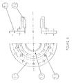
- the bearing spacer module illustrated in Figure 4 has two substantially equal halves as is indicated in the figure at 6.1 and at 6.2.
- the lower half of the spacer module, item 6.2 has a pipe connection item 6.3 either to the subsidiary cooling air from the compressor (indicated at 1.6 in Figure 3) or is open to atmosphere.
- the bearing spacer module contains the bearing housing module with its bearing.
- the upper half of a spacer may be removed without upsetting the rotor and its bearings for inspection of a bearing and to facilitate the fitting by way of the bearing an accelerometer for the measurement of vibration and a thermocouple to measure bearing temperature.
- the accelerometer and thermocouple provide valuable data on commissioning of a unit and subsequently contribute to health monitoring in service.
- the bearing housing module is illustrated in Figure 5 and comprises a bulkhead panel 7.1 that carries the bearing housing and bearing 7.2. As is indicated in Figure 2, a bearing housing module is clamped between a flange of a bearing spacer module and a flange of a generator stator module.
- the bearing module, and its bearing must be split (most conveniently diametrically) to permit assembly of the bearing if the bore of the bearing is too small for the bearing to be assembled to its rotor axially.
- this requirement implies that slider bearing such as tilting pad bearings that benefit from small diameter journals will require split bearing modules whereas rolling element bearings that do not require seats of such small diameter may be contained in unsplit bearing housings.
- a consideration of critical speeds in the first bending mode lends advantage to the use of rolling element bearings.
- Rolling element bearings do not require a necking of the rotor close to the overhung impellers. Necking reduces the first bending critical speed and makes it more difficult, if not impossible, to design so that the first bending mode critical lies above running speed.
- the through holes, 7.3 in the bulkhead, are for the passage of cooling air in to or from the air gap of the generator.
- a generator stator module is illustrated in Figure 6.
- its feature of significance is the flanging of its unsplit casing. This flanging is necessary for the assembly to it of bearing spacer modules as is indicated in Figure 2 by items 4 and 6.
- the turbine module follows the conventional design of inward flow turbines with the exception of the provisions made with relation to the second design problem that has been noted already - to protect the turbine-end bearing from the heat of the turbine.
- a preferred construction of the turbine module is illustrated in Figure 7.
- 3.1 is the backing plate on which the casing of the turbine is mounted
- 3.2 is the inlet belt of the turbine
- 3.3 are its inlet guide vanes
- 3.4 is its impeller
- 3.5 is a rotor seal mounted from the backing plate 3.1.
- Item 3.6 is a flanged ring with a split skirt as indicated at the bottom of the figure. It is split to accommodate the differential thermal expansion between its attachment to the hot turbine backing plate and the cooled plate 3.9.
- Item 3.7 is an annulus of ceramic insulation held by the ring 3.6 and with a gap at its inner radius and between its RH face and the backing plate 3.1.
- Item 3.8 is a water-cooled annulus bolted to the plate 3.9 and bearing a rotor seal 3.11 at its inner radius.
- the water-cooled annulus contains a two-start spiral baffle as indicated in the inset figure at the top LH of the figure. The water inlet and outlet are adjacent, but the spirals force the water to spiral towards the inner radius of the annulus and then to spiral outwards. The effect of the spiral is to produce a substantially constant temperature over the face of plate 3.9.
- the turbine module is attached to its bearing spacer module by the plate 3.9 that is centred by the spigot 3.12.
- the impeller of the turbine is held to the rotor by the claw coupling and tie-bolt means as has been described already for holding the compressor impeller.
- the claw or Hirth coupling is indicated at 3.10.
- the eddy currents that heat the armature of a rotor have been described already.
- the heat of the eddy currents is carried away in cooling air flowing in two paths.
- One path is the air gap between the outer surface of the armature and the bore of the stator.
- the second path is available because a rotor has the aspect of a thick walled tube. Cooling air passes in to the bore of the tube by radial holes at one end of a rotor. It passes to exhaust holes at the other end by the gap formed between the bore of the tube and a concentric cylindrical insert that forces the cooling air to wash the bore of the tube.
- a rotor module is illustrated in Figure 8. It is shown diagrammatically, and the permanent magnets of the armature and their attachment to the rotor are not shown.
- the diagram shows the thick walled tube 5.1 that represents the rotor with a concentric cylindrical insert 5.2 and radial holes 5.3 and 5.4 respectively for the inward and outward flow of cooling air.
- a thin walled tube of stainless steel or other material of high resistivity held concentrically in the bore of the rotor by the upstands indicated in the inset at the bottom of the figure.
- the insert is sprung in to the bore. It forces the cooling air to wash the bore of the rotor, and thereby, with other factors taken into consideration such as pressure drop, velocity and mass flow, to optimise the heat carried away by the cooling air.
- the concentric insert is possible only if the bore of a rotor is initially unobstructed. That is achieved by internally screw-cutting a thread at the ends of the uniform bore of a rotor, and fitting screwed end-plugs that in turn are bored and screwed for the tie bolts to hold the impellers, and to close couple two rotors.
- An end plug is indicated at 5.5 of Figure 8 and a tie-bolt at 5.6.
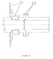
- Figure 9A illustrates the attachment to an armature of either the impeller of the compressor (1.1) or the impeller of the turbine (3.4).
- the end plug is counter bored to lengthen the tie bolt 5.6 and thereby to give it some axial flexibility so that its tightening force will vary less with differential expansion of tie bolt and impeller.
- Figure 9B illustrates the close coupling of two armatures in tandem.
- the end plugs of the armatures are respectively items 5.7 and 5.8.
- the tie bolt 5.6 is screwed in to item 5.7 and holds together the claw or Hirth coupling 5.9.
- Item 5.10 is a hollow cylinder that is a press fit in the counter bores in each armature by way of the coupling and serves to hold the ends of the armatures concentric one with another.
- Figure 9C illustrates the close coupling in tandem of two armatures when the central bearing (12 in Figure 1B) is a split slider bearing held in a bearing housing module which is also split.
- the split bearing and split housing allow the rotors to be coupled by spigot and flange.
- item 7 indicates the split bearing housing and 5.11 the flanged coupling.
- FIG. 10 The preferred flows of cooling air for a unit with two armatures in tandem is illustrated diagrammatically in Figure 10.
- item 1 is the flow of cooling air from the compressor (item 1.10 of Figure 3) to 2 and 7 which are respectively the inflows to the bearing spacers of Figure 3 and Figure 7.
- the radial holes giving access for the flow of air to the bores of the armatures are 3 and 8 respectively between the shaft seal 1.9 in Figure 3 and the adjacent bearing, and between the two shaft seals 3.5 and 3.11 of Figure 7. This positioning of holes cools the bearings before the air has received heat from other sources.
- the shaft seal 1.9 whose primary duty is to contain the leakage of air from the compressor now contains also the cooling air. There is some balance of pressure across the seal that reduces the leakage flow.
- the shaft seal 3.11 contains the leakage of cooling air and the shaft seal 3.5 contains the leakage of high temperature gas from the turbine. Both leakages escape to atmosphere via the large clearance at its inner radius of the ceramic insulator 3.7, and the space between its front face and the backing plate 3.1. The final escape is via the slots in item 3.6, or some other hole.
- the flows of air 2 and 7 also pass partly through the air gaps of the generators as indicated at 4 and 9 in Figure 10.
- the flows enter the air gaps via holes such as 7.3 in Figure 5.
- the cooling air from the compressor goes to the turbine end and enters the bore of the armature and the air gap in the same way as has been described above.
Landscapes
- Engineering & Computer Science (AREA)
- Mechanical Engineering (AREA)
- General Engineering & Computer Science (AREA)
- Structures Of Non-Positive Displacement Pumps (AREA)
- Connection Of Motors, Electrical Generators, Mechanical Devices, And The Like (AREA)
- Supercharger (AREA)
Abstract
Description
Claims (9)
- A turbomachinery electric generator arrangement comprising:wherein compressed gas for cooling components of the arrangement is directed from the rotary compressor.a rotary compressor;a generator arrangement having a rotary armature and a stator;a combustion chamber to which compressed gas is directed from the compressor;a rotary turbine to which combustion product is directed from the combustion chamber;a bearing arrangement supporting in rotation the rotary compressor, rotary armature and rotary turbine;
- A turbomachinery electric generator arrangement according to claim 1, wherein:i) the compressor has a primary compressed gas output for directing air to the combustion and a subsidiary gas output for tapping off cooling gas, preferably, wherein the subsidiary gas output is upstream of the primary gas outlet; and/orii) the compressed gas for cooling tapped off from the compressor is at a tap off pressure lower than the primary gas output from the compressor directed to the combustion chamber; and/oriii) the compressor has a radial flow impeller; and/oriv) the compressor and the turbine are provided at spaced portions of the arrangement; and/orv) the generator arrangement is provided intermediate the compressor and the turbine; and/orvi) the compressor and the turbine are overhung at opposed ends of the rotor of the arrangement; and/orvii) the compressed cooling gas tapped off from the compressor is directed to the cool the bearing arrangement; and/orvii) the bearing arrangement comprises a compressor proximal bearing and a turbine proximal bearing, the cooling gas tapped off from the compressor being directed to cool both the compressor proximal and turbine proximal bearings, preferably wherein the cooling gas tapped off from the compressor is directed along a manifold network to cool both the compressor proximal and turbine proximal bearings, the manifold including a branch directing cooling gas to the region of the turbine proximal bearing and a branch directing cooling gas to the region of the compressor proximal bearing.
- A turbomachinery electric generator arrangement according to claim1 or claim 2, wherein:i) the bearing arrangement comprises a compressor proximal bearing and a turbine proximal bearing, the cooling gas tapped off from the compressor being directed to cool both the compressor proximal and turbine proximal bearings, the cooling gas passing to the turbine proximal bearing prior to passing to the compressor proximal bearing; and/orii) the cooling gas tapped off from the compressor is directed along a cooling path, which cooling path includes the space between the generator arrangement armature and stator; and/oriii) the cooling gas tapped off from the compressor is directed along a cooling path, which cooling path includes a portion internally of the rotor, preferably wherein the armature comprises a tube having a bore in the interior, and cooling gas is directed into and out of the bore, more preferably wherein the bore includes an insert to guide the cooling gas to wash the internal bore of the armature, preferably wherein the insert preferably being:a) of high resistivity material; and/orb) located in position in the bore of the armature by a plurality of upstands projecting from the main body of the insert; and/orc) of hollow interior.
- A turbomachinery electric generator arrangement according any preceding claim, wherein:i) the generator arrangement includes a plurality of generators, each generator having a respective rotary armature and a stator, the bearing arrangement including a bearing intermediate the generators; and/orii) the bearing arrangement includes a bearing taking up axial thrust; and/oriii) the bearing arrangement includes one or more tilting pad bearings; and/oriv) the bearing arrangement includes one or more rolling element bearings; and/orv) the arrangement further comprises a shield device for thermally shielding a bearing proximate the turbine from the heat of the turbine, preferably wherein:a) the shield device comprises a liquid cooled element, preferably wherein the liquid cooled element includes an internal liquid coolant flowpath, desirably wherein the coolant flowpath extends inwardly towards the rotational axis of the rotor and subsequently outwardly away from the rotational axis of the rotor, preferably wherein the flowpath follows a spiral or helical path; and/orb) the shield device comprises an annular element; and/orc) the shield device is mounted between the turbine and the turbine proximate bearing, preferably wherein the shield device is mounted against the backing plate of the turbine; and/orvi) the bearing arrangement includes one or more bearing modules including a flanged carrier supporting a bearing element, the flanged carrier facilitating mounting of the bearing, preferably wherein the flange of the carrier of the bearing module is sandwiched between respective flanged terminal portions of other modules of the arrangement.
- A turbomachinery electric generator arrangement comprising:a rotary compressor;a generator arrangement having a rotary armature and a stator;a combustion chamber to which compressed gas is directed from the compressor;a rotary turbine to which combustion product is directed from the combustion chamber;a bearing arrangement supporting in rotation the rotary compressor stage, rotary armature and rotary turbine, the bearing arrangement including a bearing proximate the turbine; and,a shield device for thermally shielding the bearing proximate the turbine from the heat of the turbine.
- A turbomachinery electric generator arrangement according to claim 5, wherein:i) the shield device comprises a liquid cooled element, preferably wherein the liquid cooled element includes an internal liquid coolant flowpath, preferably wherein the coolant flowpath extends inwardly towards the rotational axis of the rotor and subsequently outwardly away from the rotational axis of the rotor, preferably wherein the flowpath follows a spiral path; and/orii) the shield device comprises an annular element; and/oriii) the shield device is mounted between the turbine and the turbine proximate bearing, preferably wherein the shield device is mounted against the backing plate of the turbine.
- A turbomachinery arrangement comprising:a rotary turbine;a bearing arrangement supporting in rotation the rotary turbine, the bearing arrangement including a bearing proximate the turbine; and,a shield device for thermally shielding the bearing proximate the turbine from the heat of the turbine.
- A turbomachinery electric generator arrangement of modular construction comprising:a compressor module including an impeller;a generator module including a rotary armature and a stator;a turbine module including an impeller, combustion product from a combustion chamber being directed to the turbine module;one or more bearing modules including a bearing arrangement comprising bearing spacer module and a bearing housing module, and supporting in rotation the compressor impeller, rotary armature and turbine impeller.
- A turbomachinery electric generator arrangement according to claim 8, wherein:i) one or more of the compressor module, the generator module and the turbine module are provided with respective coupling flanges, for connection to adjacently arranged modules; and/orii) a bearing spacer module is also provided having a coupling flange, the bearing spacer module being provided intermediate:the turbine module and the generator module; and/orthe compressor module and the generator module;preferably wherein:a) the flange of the bearing module abuts the flange of the bearing spacer module; and/orb) the bearing spacer module includes a casing having a plurality of apertures, slits or slots toward an end distal to the turbine module.
Applications Claiming Priority (2)
| Application Number | Priority Date | Filing Date | Title |
|---|---|---|---|
| GB0403302 | 2004-02-14 | ||
| GB0403302A GB2410982A (en) | 2004-02-14 | 2004-02-14 | Turbomachinery electric generator arrangement with component cooling |
Publications (2)
| Publication Number | Publication Date |
|---|---|
| EP1564379A2 true EP1564379A2 (en) | 2005-08-17 |
| EP1564379A3 EP1564379A3 (en) | 2014-10-08 |
Family
ID=32011917
Family Applications (1)
| Application Number | Title | Priority Date | Filing Date |
|---|---|---|---|
| EP05250843.9A Withdrawn EP1564379A3 (en) | 2004-02-14 | 2005-02-14 | Arrangement for a Turbomachine driven electric generator |
Country Status (3)
| Country | Link |
|---|---|
| US (2) | US7683497B2 (en) |
| EP (1) | EP1564379A3 (en) |
| GB (1) | GB2410982A (en) |
Cited By (8)
| Publication number | Priority date | Publication date | Assignee | Title |
|---|---|---|---|---|
| EP1707752A1 (en) * | 2004-12-23 | 2006-10-04 | Nuovo Pignone S.P.A. | Turbogenerator |
| EP1830070A3 (en) * | 2006-02-17 | 2010-09-01 | Nuovo Pignone S.p.A. | Motor compressor |
| NL2003264C2 (en) * | 2009-07-23 | 2011-01-25 | Micro Turbine Technology B V | Method for manufacturing a micro gas turbine. |
| EP1574676A3 (en) * | 2004-03-04 | 2011-08-31 | Technical Directions Inc. (TDI) | Turbine machine |
| NL2009734C2 (en) * | 2012-06-29 | 2013-12-31 | Micro Turbine Technology B V | A combination of two interconnected shafts for high-speed rotors. |
| WO2016020263A1 (en) * | 2014-08-07 | 2016-02-11 | Siemens Aktiengesellschaft | Power plant for generating electrical energy having two generator devices |
| IT202100018746A1 (en) * | 2021-07-15 | 2023-01-15 | Pierfranco Mario Stoppani | Device for generating electricity. |
| WO2024054490A1 (en) * | 2022-09-07 | 2024-03-14 | Sapphire Technologies, Inc. | Modular design of turboexpander components |
Families Citing this family (23)
| Publication number | Priority date | Publication date | Assignee | Title |
|---|---|---|---|---|
| EP2158387B1 (en) * | 2007-05-24 | 2013-04-10 | Lindenmaier GmbH | Compressor assembly |
| US8049353B1 (en) * | 2008-06-13 | 2011-11-01 | Florida Turbine Technologies, Inc. | Stackable generator arrangement |
| DE102009015862A1 (en) * | 2009-04-01 | 2010-10-07 | Siemens Aktiengesellschaft | Gear compressor rotor for cold gas applications |
| EP2378117A1 (en) * | 2010-04-16 | 2011-10-19 | Siemens Aktiengesellschaft | Wind turbine |
| ITCO20110031A1 (en) * | 2011-07-28 | 2013-01-29 | Nuovo Pignone Spa | TRAIN OF TURBOCHARGERS WITH ROTATING SUPPORTS AND METHOD |
| US8893499B2 (en) * | 2011-10-20 | 2014-11-25 | Dresser-Rand Company | Advanced super-critical CO2 expander-generator |
| ITFI20120245A1 (en) * | 2012-11-08 | 2014-05-09 | Nuovo Pignone Srl | "GAS TURBINE IN MECHANICAL DRIVE APPLICATIONS AND OPERATING METHODS" |
| CA2903320C (en) * | 2013-03-03 | 2019-07-16 | Rolls-Royce North American Technologies, Inc. | Gas turbine engine |
| EP2930314B1 (en) | 2014-04-08 | 2022-06-08 | Rolls-Royce Corporation | Generator with controlled air cooling amplifier |
| US20150369337A1 (en) * | 2014-06-23 | 2015-12-24 | Samsung Techwin Co., Ltd. | High-speed rotating machine |
| US9166458B1 (en) * | 2015-03-09 | 2015-10-20 | Gordon Charles Burns, III | Pump/generator over-unity apparatus and method |
| US10267328B2 (en) | 2015-07-21 | 2019-04-23 | Rolls-Royce Corporation | Rotor structure for rotating machinery and method of assembly thereof |
| DE102016203615A1 (en) * | 2016-03-04 | 2017-09-07 | Dürr Systems Ag | Gas Turbine System |
| US10816086B2 (en) | 2017-08-14 | 2020-10-27 | General Electric Company | Power gearbox gear arrangement |
| US10644630B2 (en) | 2017-11-28 | 2020-05-05 | General Electric Company | Turbomachine with an electric machine assembly and method for operation |
| FI3947922T3 (en) * | 2019-04-05 | 2023-04-04 | Power generation system and method to generate power by operation of such power generation system | |
| US11359635B2 (en) * | 2019-04-14 | 2022-06-14 | Hamilton Sundstrand Corporation | Power modules with regenerative compressor wheels |
| US11193474B1 (en) * | 2019-12-19 | 2021-12-07 | Bizhub Group LLC | Air powered electric generator |
| JP7372225B2 (en) * | 2020-10-20 | 2023-10-31 | 本田技研工業株式会社 | gas turbine generator |
| DE102020134759A1 (en) | 2020-12-22 | 2022-06-23 | Atlas Copco Energas Gmbh | Turbomachine and method of operating a turbomachine |
| CN114688157B (en) * | 2020-12-25 | 2024-09-10 | 上海电气电站设备有限公司 | A liquid magnetic coupling bearing device and steam turbine for steam turbine |
| CN114320608B (en) * | 2022-01-11 | 2024-09-24 | 永旭腾风新能源动力科技(北京)有限公司 | gas turbine |
| US12480449B2 (en) | 2022-08-22 | 2025-11-25 | General Electric Company | Propulsion system including an electric machine for starting a gas turbine engine |
Family Cites Families (20)
| Publication number | Priority date | Publication date | Assignee | Title |
|---|---|---|---|---|
| GB1523640A (en) | 1975-12-24 | 1978-09-06 | United Turbine Ab & Co | Gas turbine power plant |
| US4156342A (en) * | 1976-06-11 | 1979-05-29 | Westinghouse Canada Limited | Cooling apparatus for a bearing in a gas turbine |
| DE2823261C2 (en) * | 1978-05-27 | 1985-05-23 | Robert Bosch Gmbh, 7000 Stuttgart | Electric machine |
| US5087176A (en) * | 1984-12-20 | 1992-02-11 | Allied-Signal Inc. | Method and apparatus to provide thermal isolation of process gas bearings |
| JPH0284037A (en) * | 1988-09-19 | 1990-03-26 | Toshiba Corp | Claw pole type synchronous generator |
| US5795138A (en) * | 1992-09-10 | 1998-08-18 | Gozdawa; Richard | Compressor |
| US5497615A (en) * | 1994-03-21 | 1996-03-12 | Noe; James C. | Gas turbine generator set |
| DE4435322B4 (en) * | 1994-10-01 | 2005-05-04 | Alstom | Method and device for shaft seal and for cooling on the exhaust side of an axial flowed gas turbine |
| JP3030689B2 (en) * | 1995-09-08 | 2000-04-10 | 本田技研工業株式会社 | Gas turbine engine |
| US5827040A (en) * | 1996-06-14 | 1998-10-27 | Capstone Turbine Corporation | Hydrostatic augmentation of a compliant foil hydrodynamic fluid film thrust bearing |
| GB9716494D0 (en) * | 1997-08-05 | 1997-10-08 | Gozdawa Richard J | Compressions |
| US6073857A (en) * | 1998-09-14 | 2000-06-13 | Fairlane Tool Company | Co-generator utilizing micro gas turbine engine |
| EP1069313B1 (en) * | 1999-07-16 | 2005-09-14 | Man Turbo Ag | Turbo compressor |
| US6234746B1 (en) * | 1999-08-04 | 2001-05-22 | General Electric Co. | Apparatus and methods for cooling rotary components in a turbine |
| GB2410380B (en) * | 2000-11-30 | 2005-08-31 | Richard Julius Gozdawa | Rotor for electric generator or motor |
| GB0111301D0 (en) * | 2001-05-09 | 2001-06-27 | Bowman Power Systems Ltd | Power generation apparatus |
| US6622490B2 (en) * | 2002-01-11 | 2003-09-23 | Watson Cogeneration Company | Turbine power plant having an axially loaded floating brush seal |
| EP1391586B1 (en) * | 2002-08-20 | 2008-11-12 | Borgwarner, Inc. | Turbocharger |
| DE602004027993D1 (en) * | 2003-02-24 | 2010-08-19 | Pratt & Whitney Canada | BUILT-IN COOLING SYSTEM FOR A CIRCULAR MOTOR |
| US7112036B2 (en) * | 2003-10-28 | 2006-09-26 | Capstone Turbine Corporation | Rotor and bearing system for a turbomachine |
-
2004
- 2004-02-14 GB GB0403302A patent/GB2410982A/en not_active Withdrawn
-
2005
- 2005-02-14 US US11/057,582 patent/US7683497B2/en not_active Expired - Fee Related
- 2005-02-14 EP EP05250843.9A patent/EP1564379A3/en not_active Withdrawn
-
2010
- 2010-03-18 US US12/726,639 patent/US8508062B2/en not_active Expired - Fee Related
Cited By (15)
| Publication number | Priority date | Publication date | Assignee | Title |
|---|---|---|---|---|
| EP1574676A3 (en) * | 2004-03-04 | 2011-08-31 | Technical Directions Inc. (TDI) | Turbine machine |
| EP1707752A1 (en) * | 2004-12-23 | 2006-10-04 | Nuovo Pignone S.P.A. | Turbogenerator |
| US8430653B2 (en) | 2006-02-17 | 2013-04-30 | Nuovo Pignone, S.P.A. | Motor compressor |
| EP1830070A3 (en) * | 2006-02-17 | 2010-09-01 | Nuovo Pignone S.p.A. | Motor compressor |
| NO339510B1 (en) * | 2006-02-17 | 2016-12-27 | Nuovo Pignone Spa | Motor Compressor |
| WO2011010926A1 (en) | 2009-07-23 | 2011-01-27 | Micro Turbine Technology Bv | Method for manufacturing a micro gas turbine |
| CN102869853A (en) * | 2009-07-23 | 2013-01-09 | 麦科罗特迈尼科技有限公司 | Method for manufacturing a micro gas turbine |
| US9149865B2 (en) | 2009-07-23 | 2015-10-06 | Micro Turbine Technology, Bv | Method for manufacturing micro gas turbine |
| NL2003264C2 (en) * | 2009-07-23 | 2011-01-25 | Micro Turbine Technology B V | Method for manufacturing a micro gas turbine. |
| NL2009734C2 (en) * | 2012-06-29 | 2013-12-31 | Micro Turbine Technology B V | A combination of two interconnected shafts for high-speed rotors. |
| WO2014003563A1 (en) * | 2012-06-29 | 2014-01-03 | Micro Turbine Technology Bv | A combination of two interconnected shafts for high-speed rotors |
| US10598016B2 (en) | 2012-06-29 | 2020-03-24 | Micro Turbine Technology, Bv | Combination of two interconnected shafts for high-speed rotors |
| WO2016020263A1 (en) * | 2014-08-07 | 2016-02-11 | Siemens Aktiengesellschaft | Power plant for generating electrical energy having two generator devices |
| IT202100018746A1 (en) * | 2021-07-15 | 2023-01-15 | Pierfranco Mario Stoppani | Device for generating electricity. |
| WO2024054490A1 (en) * | 2022-09-07 | 2024-03-14 | Sapphire Technologies, Inc. | Modular design of turboexpander components |
Also Published As
| Publication number | Publication date |
|---|---|
| US8508062B2 (en) | 2013-08-13 |
| US7683497B2 (en) | 2010-03-23 |
| GB0403302D0 (en) | 2004-03-17 |
| US20050189772A1 (en) | 2005-09-01 |
| EP1564379A3 (en) | 2014-10-08 |
| GB2410982A (en) | 2005-08-17 |
| US20100219638A1 (en) | 2010-09-02 |
Similar Documents
| Publication | Publication Date | Title |
|---|---|---|
| US8508062B2 (en) | Turbomachinery electric generator arrangement | |
| US2591399A (en) | Power plant frame structure having air-cooling means for turbine rotors and exhaust frame struts | |
| US5685158A (en) | Compressor rotor cooling system for a gas turbine | |
| RU2416028C2 (en) | Device for cooling case of turbine in turbo-machine | |
| JP3863938B2 (en) | Removable turbine inner shell with controllable blade tip clearance | |
| US6900553B2 (en) | Gas turbomachinery generator | |
| US10240532B2 (en) | Frame junction cooling holes | |
| EP2573329A2 (en) | Air system architecture for a mid-turbine frame module | |
| US6450758B1 (en) | Cooling system for a bearing of a turbine rotor | |
| GB1270905A (en) | Cooling system for an axial flow elastic fluid utilizing machine | |
| US5201796A (en) | Gas turbine engine arrangement | |
| US11002146B1 (en) | Power generation system | |
| US6089010A (en) | System for compensating for a pressure loss in the cooling-air ducting in a gas turbine plant | |
| EP1318275B1 (en) | Structure for separating the high and low pressure turboexpanders of a gas turbine | |
| US5738488A (en) | Gland for transferring cooling medium to the rotor of a gas turbine | |
| EP1132578A2 (en) | Methods and apparatus for isolating gas turbine engine bearings | |
| EP3508688B1 (en) | Gas turbine engine and compressor | |
| US10352182B2 (en) | Internal cooling of stator vanes | |
| EP4043695A1 (en) | Tangential on-board injector | |
| US20050120719A1 (en) | Internally insulated turbine assembly | |
| CA3174071C (en) | A power generaton system | |
| EP3647542B1 (en) | Intercooled tangential air injector for gas turbine engines | |
| WO2018111276A1 (en) | Pre-swirl section for a gas turbine engine |
Legal Events
| Date | Code | Title | Description |
|---|---|---|---|
| PUAI | Public reference made under article 153(3) epc to a published international application that has entered the european phase |
Free format text: ORIGINAL CODE: 0009012 |
|
| AK | Designated contracting states |
Kind code of ref document: A2 Designated state(s): AT BE BG CH CY CZ DE DK EE ES FI FR GB GR HU IE IS IT LI LT LU MC NL PL PT RO SE SI SK TR |
|
| AX | Request for extension of the european patent |
Extension state: AL BA HR LV MK YU |
|
| RAP1 | Party data changed (applicant data changed or rights of an application transferred) |
Owner name: CENTRICOMP GROUP PLC |
|
| RIN1 | Information on inventor provided before grant (corrected) |
Inventor name: GOZDAWA, RICHARD JULIUS |
|
| 111Z | Information provided on other rights and legal means of execution |
Free format text: AT BE BG CH CY CZ DE DK EE ES FI FR GB GR HU IE IS IT LT LU MC NL PL PT RO SE SI SK TR Effective date: 20090226 |
|
| RAP1 | Party data changed (applicant data changed or rights of an application transferred) |
Owner name: YORLAND HOLINGS LIMITED |
|
| D11X | Information provided on other rights and legal means of execution (deleted) | ||
| 19U | Interruption of proceedings before grant |
Effective date: 20101013 |
|
| 19W | Proceedings resumed before grant after interruption of proceedings |
Effective date: 20121203 |
|
| RIC1 | Information provided on ipc code assigned before grant |
Ipc: F01D 25/16 20060101ALI20140507BHEP Ipc: F01D 15/10 20060101AFI20140507BHEP Ipc: F01D 25/12 20060101ALI20140507BHEP |
|
| PUAL | Search report despatched |
Free format text: ORIGINAL CODE: 0009013 |
|
| AK | Designated contracting states |
Kind code of ref document: A3 Designated state(s): AT BE BG CH CY CZ DE DK EE ES FI FR GB GR HU IE IS IT LI LT LU MC NL PL PT RO SE SI SK TR |
|
| AX | Request for extension of the european patent |
Extension state: AL BA HR LV MK YU |
|
| RIC1 | Information provided on ipc code assigned before grant |
Ipc: F01D 25/16 20060101ALI20140829BHEP Ipc: F01D 25/12 20060101ALI20140829BHEP Ipc: F01D 15/10 20060101AFI20140829BHEP |
|
| STAA | Information on the status of an ep patent application or granted ep patent |
Free format text: STATUS: THE APPLICATION IS DEEMED TO BE WITHDRAWN |
|
| 18D | Application deemed to be withdrawn |
Effective date: 20140902 |