EP4043695A1 - Tangential on-board injector - Google Patents
Tangential on-board injector Download PDFInfo
- Publication number
- EP4043695A1 EP4043695A1 EP22155000.7A EP22155000A EP4043695A1 EP 4043695 A1 EP4043695 A1 EP 4043695A1 EP 22155000 A EP22155000 A EP 22155000A EP 4043695 A1 EP4043695 A1 EP 4043695A1
- Authority
- EP
- European Patent Office
- Prior art keywords
- tobi
- gas turbine
- turbine engine
- interference fit
- central axis
- Prior art date
- Legal status (The legal status is an assumption and is not a legal conclusion. Google has not performed a legal analysis and makes no representation as to the accuracy of the status listed.)
- Granted
Links
- 238000001816 cooling Methods 0.000 claims abstract description 25
- 230000033001 locomotion Effects 0.000 claims abstract description 6
- 229910001119 inconels 625 Inorganic materials 0.000 claims description 9
- 238000006243 chemical reaction Methods 0.000 claims description 7
- 239000003570 air Substances 0.000 description 95
- 239000007789 gas Substances 0.000 description 19
- 238000012546 transfer Methods 0.000 description 8
- PXHVJJICTQNCMI-UHFFFAOYSA-N Nickel Chemical compound [Ni] PXHVJJICTQNCMI-UHFFFAOYSA-N 0.000 description 6
- 230000014759 maintenance of location Effects 0.000 description 6
- 229910001026 inconel Inorganic materials 0.000 description 5
- 239000000463 material Substances 0.000 description 5
- 238000007789 sealing Methods 0.000 description 5
- 239000000567 combustion gas Substances 0.000 description 4
- 238000004519 manufacturing process Methods 0.000 description 4
- 238000011144 upstream manufacturing Methods 0.000 description 4
- 238000004891 communication Methods 0.000 description 3
- 238000005516 engineering process Methods 0.000 description 3
- 229910052759 nickel Inorganic materials 0.000 description 3
- 229910045601 alloy Inorganic materials 0.000 description 2
- 239000000956 alloy Substances 0.000 description 2
- 230000008859 change Effects 0.000 description 2
- 238000013461 design Methods 0.000 description 2
- 239000012530 fluid Substances 0.000 description 2
- 230000013011 mating Effects 0.000 description 2
- 238000012986 modification Methods 0.000 description 2
- 230000004048 modification Effects 0.000 description 2
- VYZAMTAEIAYCRO-UHFFFAOYSA-N Chromium Chemical compound [Cr] VYZAMTAEIAYCRO-UHFFFAOYSA-N 0.000 description 1
- ZOKXTWBITQBERF-UHFFFAOYSA-N Molybdenum Chemical compound [Mo] ZOKXTWBITQBERF-UHFFFAOYSA-N 0.000 description 1
- 239000011825 aerospace material Substances 0.000 description 1
- 239000012080 ambient air Substances 0.000 description 1
- 230000000712 assembly Effects 0.000 description 1
- 238000000429 assembly Methods 0.000 description 1
- 230000004323 axial length Effects 0.000 description 1
- 238000005266 casting Methods 0.000 description 1
- 229910052804 chromium Inorganic materials 0.000 description 1
- 239000011651 chromium Substances 0.000 description 1
- 230000006835 compression Effects 0.000 description 1
- 238000007906 compression Methods 0.000 description 1
- 230000037406 food intake Effects 0.000 description 1
- 239000000446 fuel Substances 0.000 description 1
- 229910001293 incoloy Inorganic materials 0.000 description 1
- 229910000816 inconels 718 Inorganic materials 0.000 description 1
- 238000002347 injection Methods 0.000 description 1
- 239000007924 injection Substances 0.000 description 1
- 238000003754 machining Methods 0.000 description 1
- 238000003801 milling Methods 0.000 description 1
- 229910052750 molybdenum Inorganic materials 0.000 description 1
- 239000011733 molybdenum Substances 0.000 description 1
- 229910052758 niobium Inorganic materials 0.000 description 1
- 239000010955 niobium Substances 0.000 description 1
- GUCVJGMIXFAOAE-UHFFFAOYSA-N niobium atom Chemical compound [Nb] GUCVJGMIXFAOAE-UHFFFAOYSA-N 0.000 description 1
- 238000012552 review Methods 0.000 description 1
- 239000007787 solid Substances 0.000 description 1
- 230000003068 static effect Effects 0.000 description 1
- 230000035882 stress Effects 0.000 description 1
- 229910000601 superalloy Inorganic materials 0.000 description 1
- 229910052715 tantalum Inorganic materials 0.000 description 1
- GUVRBAGPIYLISA-UHFFFAOYSA-N tantalum atom Chemical compound [Ta] GUVRBAGPIYLISA-UHFFFAOYSA-N 0.000 description 1
- 230000008646 thermal stress Effects 0.000 description 1
- 238000007514 turning Methods 0.000 description 1
- 229910001247 waspaloy Inorganic materials 0.000 description 1
- 239000013585 weight reducing agent Substances 0.000 description 1
Images


Classifications
-
- F—MECHANICAL ENGINEERING; LIGHTING; HEATING; WEAPONS; BLASTING
- F01—MACHINES OR ENGINES IN GENERAL; ENGINE PLANTS IN GENERAL; STEAM ENGINES
- F01D—NON-POSITIVE DISPLACEMENT MACHINES OR ENGINES, e.g. STEAM TURBINES
- F01D5/00—Blades; Blade-carrying members; Heating, heat-insulating, cooling or antivibration means on the blades or the members
- F01D5/02—Blade-carrying members, e.g. rotors
- F01D5/08—Heating, heat-insulating or cooling means
- F01D5/081—Cooling fluid being directed on the side of the rotor disc or at the roots of the blades
-
- F—MECHANICAL ENGINEERING; LIGHTING; HEATING; WEAPONS; BLASTING
- F01—MACHINES OR ENGINES IN GENERAL; ENGINE PLANTS IN GENERAL; STEAM ENGINES
- F01D—NON-POSITIVE DISPLACEMENT MACHINES OR ENGINES, e.g. STEAM TURBINES
- F01D11/00—Preventing or minimising internal leakage of working-fluid, e.g. between stages
- F01D11/001—Preventing or minimising internal leakage of working-fluid, e.g. between stages for sealing space between stator blade and rotor
-
- F—MECHANICAL ENGINEERING; LIGHTING; HEATING; WEAPONS; BLASTING
- F01—MACHINES OR ENGINES IN GENERAL; ENGINE PLANTS IN GENERAL; STEAM ENGINES
- F01D—NON-POSITIVE DISPLACEMENT MACHINES OR ENGINES, e.g. STEAM TURBINES
- F01D5/00—Blades; Blade-carrying members; Heating, heat-insulating, cooling or antivibration means on the blades or the members
- F01D5/02—Blade-carrying members, e.g. rotors
- F01D5/08—Heating, heat-insulating or cooling means
- F01D5/081—Cooling fluid being directed on the side of the rotor disc or at the roots of the blades
- F01D5/082—Cooling fluid being directed on the side of the rotor disc or at the roots of the blades on the side of the rotor disc
-
- F—MECHANICAL ENGINEERING; LIGHTING; HEATING; WEAPONS; BLASTING
- F02—COMBUSTION ENGINES; HOT-GAS OR COMBUSTION-PRODUCT ENGINE PLANTS
- F02C—GAS-TURBINE PLANTS; AIR INTAKES FOR JET-PROPULSION PLANTS; CONTROLLING FUEL SUPPLY IN AIR-BREATHING JET-PROPULSION PLANTS
- F02C7/00—Features, components parts, details or accessories, not provided for in, or of interest apart form groups F02C1/00 - F02C6/00; Air intakes for jet-propulsion plants
- F02C7/12—Cooling of plants
- F02C7/16—Cooling of plants characterised by cooling medium
- F02C7/18—Cooling of plants characterised by cooling medium the medium being gaseous, e.g. air
-
- F—MECHANICAL ENGINEERING; LIGHTING; HEATING; WEAPONS; BLASTING
- F02—COMBUSTION ENGINES; HOT-GAS OR COMBUSTION-PRODUCT ENGINE PLANTS
- F02C—GAS-TURBINE PLANTS; AIR INTAKES FOR JET-PROPULSION PLANTS; CONTROLLING FUEL SUPPLY IN AIR-BREATHING JET-PROPULSION PLANTS
- F02C7/00—Features, components parts, details or accessories, not provided for in, or of interest apart form groups F02C1/00 - F02C6/00; Air intakes for jet-propulsion plants
- F02C7/28—Arrangement of seals
-
- F—MECHANICAL ENGINEERING; LIGHTING; HEATING; WEAPONS; BLASTING
- F02—COMBUSTION ENGINES; HOT-GAS OR COMBUSTION-PRODUCT ENGINE PLANTS
- F02C—GAS-TURBINE PLANTS; AIR INTAKES FOR JET-PROPULSION PLANTS; CONTROLLING FUEL SUPPLY IN AIR-BREATHING JET-PROPULSION PLANTS
- F02C9/00—Controlling gas-turbine plants; Controlling fuel supply in air- breathing jet-propulsion plants
- F02C9/16—Control of working fluid flow
- F02C9/18—Control of working fluid flow by bleeding, bypassing or acting on variable working fluid interconnections between turbines or compressors or their stages
-
- F—MECHANICAL ENGINEERING; LIGHTING; HEATING; WEAPONS; BLASTING
- F05—INDEXING SCHEMES RELATING TO ENGINES OR PUMPS IN VARIOUS SUBCLASSES OF CLASSES F01-F04
- F05D—INDEXING SCHEME FOR ASPECTS RELATING TO NON-POSITIVE-DISPLACEMENT MACHINES OR ENGINES, GAS-TURBINES OR JET-PROPULSION PLANTS
- F05D2220/00—Application
- F05D2220/30—Application in turbines
- F05D2220/32—Application in turbines in gas turbines
-
- F—MECHANICAL ENGINEERING; LIGHTING; HEATING; WEAPONS; BLASTING
- F05—INDEXING SCHEMES RELATING TO ENGINES OR PUMPS IN VARIOUS SUBCLASSES OF CLASSES F01-F04
- F05D—INDEXING SCHEME FOR ASPECTS RELATING TO NON-POSITIVE-DISPLACEMENT MACHINES OR ENGINES, GAS-TURBINES OR JET-PROPULSION PLANTS
- F05D2240/00—Components
- F05D2240/55—Seals
- F05D2240/56—Brush seals
-
- F—MECHANICAL ENGINEERING; LIGHTING; HEATING; WEAPONS; BLASTING
- F05—INDEXING SCHEMES RELATING TO ENGINES OR PUMPS IN VARIOUS SUBCLASSES OF CLASSES F01-F04
- F05D—INDEXING SCHEME FOR ASPECTS RELATING TO NON-POSITIVE-DISPLACEMENT MACHINES OR ENGINES, GAS-TURBINES OR JET-PROPULSION PLANTS
- F05D2260/00—Function
- F05D2260/14—Preswirling
-
- F—MECHANICAL ENGINEERING; LIGHTING; HEATING; WEAPONS; BLASTING
- F05—INDEXING SCHEMES RELATING TO ENGINES OR PUMPS IN VARIOUS SUBCLASSES OF CLASSES F01-F04
- F05D—INDEXING SCHEME FOR ASPECTS RELATING TO NON-POSITIVE-DISPLACEMENT MACHINES OR ENGINES, GAS-TURBINES OR JET-PROPULSION PLANTS
- F05D2260/00—Function
- F05D2260/20—Heat transfer, e.g. cooling
- F05D2260/201—Heat transfer, e.g. cooling by impingement of a fluid
-
- F—MECHANICAL ENGINEERING; LIGHTING; HEATING; WEAPONS; BLASTING
- F05—INDEXING SCHEMES RELATING TO ENGINES OR PUMPS IN VARIOUS SUBCLASSES OF CLASSES F01-F04
- F05D—INDEXING SCHEME FOR ASPECTS RELATING TO NON-POSITIVE-DISPLACEMENT MACHINES OR ENGINES, GAS-TURBINES OR JET-PROPULSION PLANTS
- F05D2260/00—Function
- F05D2260/30—Retaining components in desired mutual position
- F05D2260/37—Retaining components in desired mutual position by a press fit connection
-
- F—MECHANICAL ENGINEERING; LIGHTING; HEATING; WEAPONS; BLASTING
- F05—INDEXING SCHEMES RELATING TO ENGINES OR PUMPS IN VARIOUS SUBCLASSES OF CLASSES F01-F04
- F05D—INDEXING SCHEME FOR ASPECTS RELATING TO NON-POSITIVE-DISPLACEMENT MACHINES OR ENGINES, GAS-TURBINES OR JET-PROPULSION PLANTS
- F05D2260/00—Function
- F05D2260/60—Fluid transfer
- F05D2260/602—Drainage
- F05D2260/6022—Drainage of leakage having past a seal
Definitions
- the application relates generally to gas turbine engine component cooling and, more particularly, to a tangential on-board injector (TOBI) assembly.
- TOBI tangential on-board injector
- TOBI tangential on-board injector
- a gas turbine engine comprising: a casing assembly extending circumferentially around a central axis of the gas turbine engine, the casing assembly located proximate a turbine section of the gas turbine engine; a tangential on-board injector (TOBI) having a body annularly extending around the central axis, the body defining a plurality of air passages extending in a radial direction relative to the central axis, the plurality of air passages circumferentially distributed about the central axis and directing cooling air toward a turbine rotor of the turbine section of the gas turbine engine; and an interference fit between a face of the body and a face of a member of the casing assembly, the interference fit defining a fastener-free engagement between the member of the casing and the TOBI to prevent relative movement therebetween.
- TOBI tangential on-board injector
- the gas turbine engine as defined above and described herein may further include, in whole or in part, and in any combination, one or more of the following additional elements.
- a reaction force between the TOBI and the member of the casing at the interference fit is in a radial direction relative to the central axis.
- the interference fit includes a second interference fit between a second face of the body and the member of the casing assembly, inlets of the plurality of air passages disposed axially between the interference fit and the second interference fit.
- reaction forces between the TOBI and the member of the casing at the interference fits are in a radial direction relative to the central axis.
- the body includes a central section defining the plurality of air passages and a first lateral section, the first lateral section being a protrusion extending axially from the central section, the protrusion defining the face of the body, the interference fit defined between the protrusion and the member of the casing assembly.
- the body includes a second lateral section, the interference fit including a second interference fit between the second lateral section and the member of the casing assembly.
- the body of the TOBI defines secondary air passages for directing the cooling air toward an annular gaspath of the gas turbine engine.
- the body of the TOBI includes a central section defining the plurality of air passages and tabs secured to the central section, the tabs extending circumferentially around the central axis and protruding radially away from the central axis, the secondary air passages defined circumferentially between the tabs.
- an alignment protrusion extends from one of the tabs, the alignment protrusion received within an aperture defined by the member of the casing assembly when the secondary air passages are fluidly connected to air passages defined by the member of the casing assembly.
- the casing assembly includes a support flange protruding radially inwardly toward the central axis, the tabs disposed axially between the support flange and the member of the casing assembly.
- the body further includes an annular protrusion extending axially from the central section relative to the central axis, the annular protrusion extending circumferentially around the central axis, the annular protrusion defining tertiary air passages.
- the TOBI is made of Inconel 625 TM .
- the member of the casing assembly is a bearing housing extending circumferentially around the central axis, the bearing housing secured to one or more of casings of the casing assembly, the face of the member of the casing assembly defined by the bearing housing, the interference fit defined between the bearing housing and the body of the TOBI.
- At least one brush seal is secured to the TOBI via a second interference fit between the body of the TOBI and the at least one brush seal.
- a tangential in-board injector (TOBI) assembly for a gas turbine engine, comprising: a bearing housing securable to a casing of the gas turbine engine, the bearing housing extending circumferentially around a central axis; a TOBI having: a central section defining primary air passages circumferentially distributed about the central axis, the air primary air passages extending in a direction having a radial component relative to the central axis, and a lateral section extending from the central section; and an interference fit between the bearing housing and the lateral section of the TOBI, the interference fit defining a fastener-free engagement between the bearing housing and the TOBI.
- TOBI tangential in-board injector
- the TOBI assembly as defined above and described herein may further include, in whole or in part, and in any combination, one or more of the following additional elements.
- the TOBI defines a second lateral section extending from the central section, the central section located between the lateral section and the second lateral section, the second lateral section defining a second face sized to define a second interference fit with the bearing housing.
- the lateral section is a protrusion extending annularly around the central axis, the protrusion defining secondary air passages.
- the protrusion defines cut outs circumferentially distributed around the central axis, the cut outs defining the secondary air passages.
- the second lateral section defines tabs extending circumferentially around the central axis, tertiary air passages defined circumferentially between the tabs.
- an alignment protrusion extends from one of the tabs, the alignment protrusion sized to be received within an aperture defined by the bearing housing when the tertiary air passages are fluidly connected with air passages defined by the bearing housing and with the secondary air passages.
- Fig. 1 illustrates a gas turbine engine 10 of a type preferably provided for use in subsonic flight, generally comprising in serial flow communication a fan 12 through which ambient air is propelled, a compressor section 14 for pressurizing the air, a combustor 16 in which the compressed air is mixed with fuel and ignited for generating an annular stream of hot combustion gases, and a turbine section 18 for extracting energy from the combustion gases.
- Components of the gas turbine engine 10 rotate about a longitudinal central axis 11.
- the turbine section 18 includes a stator assembly 18A and a rotor assembly 18B.
- An annular gaspath 15 for the hot combustion gases is provided downstream of the combustor 16, and extends axially between alternating rows of stator vanes 18C of the stator assembly 18A, and rotor blades 18D of the rotor assembly 18B.
- annular cavity 13 is formed within the stator assembly 18A and it functions in part as a reservoir for receiving cooling air from its source, for example, the discharge of the compressor section 14.
- the stator assembly 18A may be mounted to, or part of, a casing of the engine 10, and may therefore sometimes be referred to herein as a casing assembly.
- the cooling air is provided to the rotor assembly 18B to cool the rotor blades 18D, as described in detail below.
- immediately downstream of the row of stator vanes 18C is disposed the row of rotor blades 18D.
- the rotor blades 18D rotate about the central axis 11, and extend radially outwardly from a supporting rotor disk 18E via respective rotor blade roots 18F, which are mounted in the supporting rotor disk 18E.
- the supporting rotor disk 18E includes a plurality of inlets, each communicating with internal passages of the rotor blade root 18F and the rotor blade 18D, through which the cooling air is flows during operation of the engine to cool the rotor blade 18D.
- a Tangential On-Board Injection (TOBI) assembly may be used to direct cooling air toward a rotor of the turbine section 18.
- TOBI Tangential On-Board Injection
- Typical TOBI assemblies are bolted to a casing of the gas turbine engine 10 using mating flanges and bolts. Since a part of the TOBI includes a flange that extends toward the gas path, it is subjected to high temperatures that may cause thermal stress. Moreover, such flange of the TOBI is mechanically coupled to a flange of a stator assembly of the turbine section. Hence, mechanical forces imparted on the stator assembly may be transmitted to the TOBI. Moreover, in some cases, such a bolted connection may prevent leaving sufficient space to receive the TOBI.
- the TOBI assembly 120 helps to direct the cooling air in a direction of rotation of the rotor assembly 18B and further into the rotor assembly 18B to cool components thereof, such as the rotor blades 18D.
- the TOBI assembly 120 includes a TOBI 130 to increase the flow tangential velocity to reduce the losses and heat pickup due to windage, and a cover plate, which may also be referred to as a rotatable back plate or simply back plate.
- the cover plate is a rotating component, disc plate, disc cover, rotating cover and rotating cover plate, 40 to distribute the cooling air to the rotor assembly 18B, both of which are now described.
- the TOBI 130 is a stationary component.
- the TOBI 130 does not rotate with the rotor assembly 18B or with the cover plate 40.
- the TOBI 130 is made stationary because a body 131 of the TOBI 130 is non-rotating relative to the stator assembly 18A.
- the expression "static" could be interpreted as a component rotating at a different speed, including counter-rotation.
- the TOBI 130 defines circumferentially spaced-apart passages 132.
- the passages 132 of the TOBI 130 may be oriented in a tangential angle towards the direction of rotation of the rotor assembly 18B, extend radially inwardly toward the axis 11 and terminate at nozzles 34, which are provided to inject the cooling air from the cavity 13 into an annular transfer chamber 136 disposed radially inwardly from the nozzles 34.
- the transfer chamber 36 is a plenum in which the cooling air collects before it is transferred or provided to the cover plate 40. In operation, the cooling air enters the cavity 13 and is received by the TOBI 130 before being discharged by the nozzles 34 into the transfer chamber 36, and then to the rotating cover plate 40.
- the nozzles 34 impart a swirl flow vector or swirling movement to the cooling air discharged into the transfer chamber 36, and also impart a radial flow vector being transverse or normal to the axis 11.
- the transfer chamber 36 is sealed with seals 160, which engage the rotating cover plate 40 to prevent or reduce leakage of cooling air from the transfer chamber 36.
- the TOBI 130 is shown as a "radial" TOBI because the cooling air enters the TOBI 130 along a radial flow path.
- the TOBI 130 is an axial TOBI where the cooling air enters the TOBI 130 along an axial flow path.
- a radial TOBI may be preferred because of its smaller axial length when compared to an axial TOBI.
- the cover plate 40 is mounted to the rotor assembly 18B to rotate with the rotor assembly 18B about the same axis 11. Rotation of the rotor assembly 18B causes rotation of the cover plate 40.
- the cover plate 40 is a cover plate or rotor cover that is positioned axially downstream or aft of the TOBI 130.
- the cover plate 40 has an annular shape in the depicted embodiment.
- the cover plate 40 is mounted upstream of the rotor disk 18E to rotate with it.
- the cover plate 40 is mounted such that the radially outer periphery of the cover plate 40 is forced by a centrifugal force to abut the rotor blade root 18F as the rotor assembly 18B rotates about the axis 11 so that an annular and radial passage 42 is formed between the rotor disk 18E and the cover plate 40.
- Other embodiments for mounting the cover plate 40 are possible and within the scope of the present disclosure.
- the TOBI 130 is secured to a member of a casing assembly 150 via at least one interference fit.
- two interference fits are used to secure the TOBI 130 to the casing assembly 150. More than two interference fits may be used. That is, the TOBI 130 does not rely on bolted flanges as attachment to the casing assembly 150.
- the one or more interference fit between the TOBI 130 and the casing assembly 150 defines a fastener-free engagement between the casing assembly 150 and the TOBI 130.
- the one or more interference fit therefore define a fastener-free engagement between the TOBI 130 and the casing assembly 150 to prevent relative movement therebetween.
- the TOBI may be secured to the casing assembly 150 solely via one or more interference fits I1, I2 as it will be discussed below.
- the one or more interference fit used to secure the TOBI 130 to the casing assembly 150 creates a majority (e.g., more than 50%) of a retention force between the TOBI 130 and the casing assembly 130.
- the one or more interference fit may create substantially all of the retention force via which the TOBI 130 is secured to the casing assembly 150.
- the TOBI 130 may therefore be free of bolted connection to the casing assembly 150.
- An interference fit is also known as a press fit or a friction fit and is present when a tight fit is present between mating parts.
- An interference fit may be provided by having a first component having a radially inner surface of a diameter smaller than that of a radially outer surface of a second component. The interference fit is provided between the radially inner and outer surfaces when the first component is assembled to the second component. In some cases, an interference fit is also referred to as a spigot fit. To create such an interference fit between two components, a temperature change may be imparted to one or more of the two components to induce thermal change of dimension enough to engage the two components together.
- the interference fit is created when the two components revert to their original temperature.
- the interference fit may be present when the engine 10 is not in operation or may arise when the engine 10 is running as a result of thermal growth.
- the interference fit may be created by forcefully engaging two components together.
- a combustor outer liner 149 of the combustor of the engine 10 and the stator assembly 18a are secured to the casing assembly 150 via two flanges, namely an upstream flange 151 for the outer liner 149 and a downstream flange 152 for the stator assembly 18a. These two flanges 151, 152 are directly secured to one another.
- fasteners such as bolts, extend through registering and circumferentially distributed apertures defined through the two flanges 151, 152.
- the downstream flange 152 may also be referred to as an inner rear support.
- the casing assembly 150 includes a bearing housing 153.
- the outer liner 149 and the stator assembly 18a are herein secured to the casing assembly 150 via the bearing housing 153 and via the first and second flanges 151, 152.
- the bearing housing 153 includes a flange 154 that defines apertures configured to register with the apertures defined through the upstream and downstream flanges 151, 152.
- Fasteners such as bolts, extend through the apertures defines through the three flanges to secure them to one another.
- the TOBI 130 includes a body 131 that extends circumferentially all around the central axis 11.
- the body 131 may include a plurality of circumferential sections distributed around the central axis 11.
- the body 131 of the TOBI 130 extends annularly all around the central axis 11.
- the body 131 of the TOBI 130 is secured to the bearing housing 153 via the two interference fits I1, 12.
- the TOBI 130 may be secured to another member of the casing assembly 150.
- the interference fits may be defined between the TOBI 130 and a casing of the casing assembly 150.
- a casing may be, for instance, a gas generator case.
- the body 131 defines primary air passages 132 for flowing cooling air from, for instance, the compressor section 14 toward components of the turbine section 18 in need of cooling.
- the primary air passages 132 are defined axially between the two interference fits I1, 12.
- the two interference fits 11, I2 may therefore act as seals to limit air diverting away from the primary air passages 132.
- the primary air passages 132 extend from inlets to outlets.
- the inlets are located radially outwardly from the outlets relative to the central axis 11.
- the inlets may be circumferentially offset from the outlets to induce a tangential component in the flow exiting the primary air passages 132. An axial offset between the inlets and the outlets is possible.
- the TOBI 130 includes a central section 133, a first lateral section 134, and a second lateral section 135.
- the primary air passages 132 are defined by the central section 133, which is located between the first and second lateral sections 134, 135.
- the inlets of the primary air passages 132 are in the present embodiment located between the first and second lateral sections 134, 135.
- the first lateral section 134 is in the shape of an annular protrusion extending axially from the central section 133 relative to the central axis 11.
- the annular protrusion extends annularly around the central axis 11.
- the first lateral section 134 defines a first face 134A that faces away from the central axis 11.
- the first face 134A of the first lateral section 134 is normal to a radial direction relative to the central axis 11.
- the second lateral section 135 defines a second face 135A that faces away from the central axis 11.
- the second face 135A of the second lateral section 135 is normal to the radial direction. Therefore, reaction forces between the TOBI 130 and the bearing housing 153 at the one or more interference fits I1, I2 are in a radial direction relative to the central axis 11.
- the radial reaction forces create axial and circumferential retention forces between the TOBI 130 and the bearing housing 153.
- the retention forces may also include friction forces.
- reaction forces may be exerted in an axial and/or a circumferential direction relative to the central axis 11.
- a TOBI may be received between two axially spaced-apart members and axial interference fits between the TOBI and those two members may prevent relative motion therebetween.
- the first interference fit I1 is defined between a first face 153A of the bearing housing 153 and the first face 134A of the first lateral section 134 of the TOBI 130.
- the second interference fit I2 is defined between a second face 153B of the bearing housing 153 and the second face 135A of the second lateral section 135 of the TOBI 130. It will be understood that, in an alternate embodiment, only one interference fit may be used to secure the TOBI 130 to the bearing housing 153. Dimensions of surfaces defining the interference fit may be selected to ensure proper retention of the TOBI 130 to the casing assembly 150.
- the interference fits I1, I2 are defined between radially-outwardly facing faces of the TOBI 130 and between radially-inwardly facing face of the bearing housing 153.
- the interference fits may be defined at radially-inwardly facing faces of the TOBI 130.
- the second lateral section 135 of the TOBI 130 includes tabs 136 that are circumferentially distributed about the central axis 11. In the embodiment shown, three tabs 136 are provided, but more or less tabs may be used.
- the tabs 136 extend radially away from the central section 133. In the present embodiment, the tabs 136 extend radially outwardly from the central section 133 and away from the central axis 11.
- the tabs 136 are located axially between the inner rear support 152 of the casing assembly 150 and the bearing housing 153.
- One of the tabs 136 defines an alignment protrusion 137 that is sized to engage an aperture in the bearing housing 153 as explained below. Having the tabs 136 axially between the bearing housing 153 and the inner rear support 152 may assist in axially locating the TOBI 130 relative to the casing assembly 150.
- the TOBI 130 is used to distribute compressed air extracted from the compressor section 14 ( Fig. 1 ) at two different compression stages of the compressor section 14.
- two different air flows of cooling air F1, F2 are used.
- the first flow F1 is at a higher pressure than the second flow F2.
- the first flow F1 may include air at a first pressure whereas the second flow F2 may include air at a second pressure less than the first pressure.
- the first and second flows F1, F2 may be extracted at different bleed ports of the compressor section 14.
- the first flow F1 flows from the cavity 13 and is injected into the radial passage 42 formed between the rotor disk 18E and the cover plate 40.
- the second flow F2 is injected toward the annular gaspath 15 and may be used to limit combustion gases form being ingested via gaps between stator and rotor rims.
- the bearing housing 153 defines primary air passages 155 and secondary air passages 156.
- Each of the primary air passages 155 is disposed circumferentially between two adjacent ones of the secondary air passages 156.
- the primary air passages 155 are circumferentially interspaced by the secondary air passages 156 such that air flowing in the primary air passages 155 is not mixed with air flowing in the secondary air passages 156.
- the primary air passages 155 of the bearing housing 153 provide fluid communication between the cavity 13 that receives compressed air from the compressor section 14 and the primary passages 132 of the TOBI 130.
- Air of the first flow F1 flows along a first flow path from the cavity 13 through the primary air passages 155 of the bearing housing 153 and through the primary air passages 132 of the TOBI 130 to reach the annular and radial passage 42 formed between the rotor disk 18E and the cover plate 40.
- the TOBI 130 further defines secondary air passages 139 that communicates with the secondary air passages 156 of the bearing housing 153.
- the secondary air passages 139 are defined by spaces between two circumferentially adjacent tabs 136 of the second lateral section 135 of the TOBI 130. Three of those spaces are present, but more or less spaces, depending on the number of tabs 136, may be used.
- the alignment protrusion 137 is received within the aperture of the bearing housing 153 when the secondary air passages 139 of the TOBI 130 are in register for fluid communication with the secondary air passages 156 of the bearing housing 153.
- the air of the second flow F2 flows from within the secondary air passages 156 of the bearing housing 153 into the secondary air passages 139 of the TOBI 130 and then flows through apertures 152A defined through the inner rear support 152 before flowing toward the annular gaspath 15 to limit ingestion of hot gases.
- the TOBI 130 also includes tertiary air passages 138. These tertiary air passages 138 are defined by cut outs 138A in the first lateral section 134 of the TOBI 130. Three cut-touts 138A are provided in the embodiment shown, but more or less cut outs may be used.
- the tertiary air passages 138 are circumferentially offset from the secondary air passages 139 so that they do not communicate with one another.
- the tertiary air passages 138 of the TOBI 130 may flow air received from tertiary air passages defined by the bearing housing 153. This air may be flown into a cavity 13A adjacent a seal of the bearing housing 153 for pressurizing a bearing cavity thereof.
- two seals 160 are secured to the TOBI 130 and are axially spaced apart from one another relative to the central axis 11.
- Each of those two seals 160 are brush seals, but any other suitable kind of seals may be used.
- the two seals 160 are annularly extending around the central axis 11 and are disposed on opposite sides of annular transfer chamber 36. The two seals 160 are used to limit the compressed air injected into the annular transfer chamber 36 from leaking out therefrom and to direct the compressed air toward the radial passage 42 for cooling the rotor disk and blades.
- each of the two seals 160 is secured to a respective one of the first lateral section 134 and the second lateral section 135.
- interference fits are provided between radially-inwardly facing surfaces of the first and second lateral sections 134, 135 of the TOBI 130 and radially-outwardly facing surfaces of the seals 160.
- a front one of the seals 160 is axially aligned with a front interference fit I1 defined between the TOBI 130 and the bearing housing 153.
- the rear one of the seals 160 is axially offset from the rear interference fit 12.
- sealing members such as W-seals or any other suitable type of seal, are disposed at locations for forcing the compressed air along the first and second flows F1, F2.
- a first sealing member 162 is provided between the bearing housing 153 and the inner rear support 152.
- a second sealing member 163 is disposed between the second lateral section 135 of the TOBI 130 and the inner rear support 152. The second sealing member 163 is received within a groove defined by the second lateral section 135 of the TOBI 130.
- the first and second sealing members 162, 163 are respectively disposed radially outwardly and inwardly of the tertiary air passages 139 of the TOBI 130 and apertures 152A defined by the inner rear support 152 to direct the compressed air toward said apertures 152A.
- the TOBI 130 is separated from the inner rear support 152. This may help in facilitating assembly of the TOBI 130.
- the TOBI 130 and brush seals 160 may be secured to one another first and an assembly of the TOBI 130 and brush seals 160 may be installed in the engine 10.
- the TOBI 130 may be machined or otherwise formed from a solid part, and may be composed from a suitable material.
- the presently disclosed TOBI 130 is made of Inconel 625 TM , but may also be made of a similarly suitable material selected from the group of Inconel 718 TM , Incoloy 901 TM , Haynes 242 TM , and Inconel 100 TM .
- Such a material is preferred over other possible aerospace materials, such as those of the group comprising Inconel 713C TM , Waspaloy TM , and Mar-M-247 TM .
- the TOBI 130 is composed of, and may be entirely made of, Inconel 625 TM .
- Inconel 625 TM is a nickel-based alloy, or super-alloy, composed of more than 50% weight of nickel.
- Inconel 625 TM may include from 20% to 23%, preferably 21.5% weight of chromium, from 8% to 10%, preferably 9% weight of molybdenum, from 3.15% to 4.15%, preferably 3.65% weight of niobium/tantalum, and a remainder of nickel.
- Inconel 625 TM may be more machineable than Inconel 713C TM . More machineable implies may less manufacturing time and/or fewer tools or manufacturing operations may be required. Inconel 625 TM may be less expensive than certain other alloys, such as Inconel 713C TM . This may allow costs savings both on material costs and on manufacturing costs. Inconel 713C TM is used in certain prior art TOBI designs, when a bolted flange is present to ensure that the TOBI withstand the mechanical and thermal forces imparted on it.
- the TOBI 130 may mechanically and thermally decouple the TOBI 130 from the stator assembly 18A, which may allow manufacturing the TOBI 130 of a less expensive material (e.g.: Inconel 625 TM ).
- the TOBI 130 may be a turned part that may then be milled to produce periodical features. Turning all the diametric features during the same machining operation may allow to have a better control between the datum and all the other features. All the cooling air passages are machined holes, which may also help reducing the part cost when comparing with complex airfoil shape that may require more milling operations or even more complex shapes that require a casting.
- the disclosed TOBI 130 may facilitate assembly of the turbine vanes and may reduce leakage and may reduce weight because the TOBI 130 does not include a bolted flange.
- the removal of the bolted flange may limit leakage since air can no longer leak through a bolted connection.
- the TOBI 130 may be more effective in meeting durability requirements.
- the increase of the life of the TOBI 130 may be achieved by providing the TOBI 130 separated (e.g., not bolted or otherwise directly secured) from the inner rear support 152. This and having the TOBI 130 secured to the bearing housing 153 or other member of the casing assembly 150 may isolate the TOBI 130 from thermal and mechanical stresses that may impede its lifespan.
- the disclosed TOBI 130 is a single piece design with air passages fully contained in this single piece.
- the primary air passages 132 eighteen in the present embodiment, are machined in the part.
- the two interference fits I1, I2 holding the TOBI 130 may allow for a better control on air flow and may increase part durability.
Abstract
Description
- The application relates generally to gas turbine engine component cooling and, more particularly, to a tangential on-board injector (TOBI) assembly.
- Blades, vanes, and other components of gas turbine engines which are heated by a hot gas stream, such as turbine components for example, can be cooled by air compressed upstream within the engine and flowed to the turbine components. A tangential on-board injector (TOBI) is used for this purpose, where an inlet of the TOBI receives compressed air, typically produced by the compressor, and discharges a stream of cooling air tangentially to the rotating turbine assembly. Improvements of such TOBIs are however sought.
- In one aspect, there is provided a gas turbine engine comprising: a casing assembly extending circumferentially around a central axis of the gas turbine engine, the casing assembly located proximate a turbine section of the gas turbine engine; a tangential on-board injector (TOBI) having a body annularly extending around the central axis, the body defining a plurality of air passages extending in a radial direction relative to the central axis, the plurality of air passages circumferentially distributed about the central axis and directing cooling air toward a turbine rotor of the turbine section of the gas turbine engine; and an interference fit between a face of the body and a face of a member of the casing assembly, the interference fit defining a fastener-free engagement between the member of the casing and the TOBI to prevent relative movement therebetween.
- The gas turbine engine as defined above and described herein may further include, in whole or in part, and in any combination, one or more of the following additional elements.
- In some embodiments, a reaction force between the TOBI and the member of the casing at the interference fit is in a radial direction relative to the central axis.
- In some embodiments, the interference fit includes a second interference fit between a second face of the body and the member of the casing assembly, inlets of the plurality of air passages disposed axially between the interference fit and the second interference fit.
- In some embodiments, reaction forces between the TOBI and the member of the casing at the interference fits are in a radial direction relative to the central axis.
- In some embodiments, the body includes a central section defining the plurality of air passages and a first lateral section, the first lateral section being a protrusion extending axially from the central section, the protrusion defining the face of the body, the interference fit defined between the protrusion and the member of the casing assembly.
- In some embodiments, the body includes a second lateral section, the interference fit including a second interference fit between the second lateral section and the member of the casing assembly.
- In some embodiments, the body of the TOBI defines secondary air passages for directing the cooling air toward an annular gaspath of the gas turbine engine.
- In some embodiments, the body of the TOBI includes a central section defining the plurality of air passages and tabs secured to the central section, the tabs extending circumferentially around the central axis and protruding radially away from the central axis, the secondary air passages defined circumferentially between the tabs.
- In some embodiments, an alignment protrusion extends from one of the tabs, the alignment protrusion received within an aperture defined by the member of the casing assembly when the secondary air passages are fluidly connected to air passages defined by the member of the casing assembly.
- In some embodiments, the casing assembly includes a support flange protruding radially inwardly toward the central axis, the tabs disposed axially between the support flange and the member of the casing assembly.
- In some embodiments, the body further includes an annular protrusion extending axially from the central section relative to the central axis, the annular protrusion extending circumferentially around the central axis, the annular protrusion defining tertiary air passages.
- In some embodiments, the TOBI is made of Inconel 625™.
- In some embodiments, the member of the casing assembly is a bearing housing extending circumferentially around the central axis, the bearing housing secured to one or more of casings of the casing assembly, the face of the member of the casing assembly defined by the bearing housing, the interference fit defined between the bearing housing and the body of the TOBI.
- In some embodiments, at least one brush seal is secured to the TOBI via a second interference fit between the body of the TOBI and the at least one brush seal.
- In another aspect, there is provided a tangential in-board injector (TOBI) assembly for a gas turbine engine, comprising: a bearing housing securable to a casing of the gas turbine engine, the bearing housing extending circumferentially around a central axis; a TOBI having: a central section defining primary air passages circumferentially distributed about the central axis, the air primary air passages extending in a direction having a radial component relative to the central axis, and a lateral section extending from the central section; and an interference fit between the bearing housing and the lateral section of the TOBI, the interference fit defining a fastener-free engagement between the bearing housing and the TOBI.
- The TOBI assembly as defined above and described herein may further include, in whole or in part, and in any combination, one or more of the following additional elements.
- In some embodiments, the TOBI defines a second lateral section extending from the central section, the central section located between the lateral section and the second lateral section, the second lateral section defining a second face sized to define a second interference fit with the bearing housing.
- In some embodiments, the lateral section is a protrusion extending annularly around the central axis, the protrusion defining secondary air passages.
- In some embodiments, the protrusion defines cut outs circumferentially distributed around the central axis, the cut outs defining the secondary air passages.
- In some embodiments, the second lateral section defines tabs extending circumferentially around the central axis, tertiary air passages defined circumferentially between the tabs.
- In some embodiments, an alignment protrusion extends from one of the tabs, the alignment protrusion sized to be received within an aperture defined by the bearing housing when the tertiary air passages are fluidly connected with air passages defined by the bearing housing and with the secondary air passages.
- Reference is now made to the accompanying figures in which:
-
Fig. 1 is a schematic cross sectional view of a gas turbine engine; -
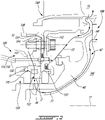
Fig. 2 is a cross-section view of a TOBI assembly in accordance with another embodiment that may be used with the engine ofFig. 1 ; -
Fig. 3 is an enlarged view of a portion ofFig. 2 ; -
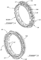
Fig. 4 is a front three dimensional view of the TOBI ofFig. 2 ; and -
Fig. 5 is a rear three-dimensional view of the TOBI ofFig. 2 . -
Fig. 1 illustrates agas turbine engine 10 of a type preferably provided for use in subsonic flight, generally comprising in serial flow communication afan 12 through which ambient air is propelled, acompressor section 14 for pressurizing the air, acombustor 16 in which the compressed air is mixed with fuel and ignited for generating an annular stream of hot combustion gases, and aturbine section 18 for extracting energy from the combustion gases. Components of thegas turbine engine 10 rotate about a longitudinalcentral axis 11. - The
turbine section 18 includes astator assembly 18A and arotor assembly 18B. Anannular gaspath 15 for the hot combustion gases is provided downstream of thecombustor 16, and extends axially between alternating rows ofstator vanes 18C of thestator assembly 18A, androtor blades 18D of therotor assembly 18B. - Referring to
Figs. 2-3 , anannular cavity 13 is formed within thestator assembly 18A and it functions in part as a reservoir for receiving cooling air from its source, for example, the discharge of thecompressor section 14. Thestator assembly 18A may be mounted to, or part of, a casing of theengine 10, and may therefore sometimes be referred to herein as a casing assembly. The cooling air is provided to therotor assembly 18B to cool therotor blades 18D, as described in detail below. InFig. 2 , immediately downstream of the row ofstator vanes 18C is disposed the row ofrotor blades 18D. Therotor blades 18D rotate about thecentral axis 11, and extend radially outwardly from a supportingrotor disk 18E via respectiverotor blade roots 18F, which are mounted in the supportingrotor disk 18E. The supportingrotor disk 18E includes a plurality of inlets, each communicating with internal passages of therotor blade root 18F and therotor blade 18D, through which the cooling air is flows during operation of the engine to cool therotor blade 18D. - A Tangential On-Board Injection (TOBI) assembly may be used to direct cooling air toward a rotor of the
turbine section 18. One such TOBI assembly is described in U.S. Patent Application Publication No.US 2020/0141241 , the entire contents of which are incorporated herein by reference. Typical TOBI assemblies are bolted to a casing of thegas turbine engine 10 using mating flanges and bolts. Since a part of the TOBI includes a flange that extends toward the gas path, it is subjected to high temperatures that may cause thermal stress. Moreover, such flange of the TOBI is mechanically coupled to a flange of a stator assembly of the turbine section. Hence, mechanical forces imparted on the stator assembly may be transmitted to the TOBI. Moreover, in some cases, such a bolted connection may prevent leaving sufficient space to receive the TOBI. - Referring to
Figs. 2-3 , a TOBI that may at least partially alleviate this drawback is shown at 120. TheTOBI assembly 120 helps to direct the cooling air in a direction of rotation of therotor assembly 18B and further into therotor assembly 18B to cool components thereof, such as therotor blades 18D. The TOBIassembly 120 includes aTOBI 130 to increase the flow tangential velocity to reduce the losses and heat pickup due to windage, and a cover plate, which may also be referred to as a rotatable back plate or simply back plate. The cover plate is a rotating component, disc plate, disc cover, rotating cover and rotating cover plate, 40 to distribute the cooling air to therotor assembly 18B, both of which are now described. - In the embodiment shown in
Figs. 2-3 , theTOBI 130 is a stationary component. The TOBI 130 does not rotate with therotor assembly 18B or with thecover plate 40. In the depicted embodiment, the TOBI 130 is made stationary because abody 131 of theTOBI 130 is non-rotating relative to thestator assembly 18A. In a particular embodiment, the expression "static" could be interpreted as a component rotating at a different speed, including counter-rotation. - The TOBI 130 defines circumferentially spaced-
apart passages 132. Thepassages 132 of theTOBI 130 may be oriented in a tangential angle towards the direction of rotation of therotor assembly 18B, extend radially inwardly toward theaxis 11 and terminate atnozzles 34, which are provided to inject the cooling air from thecavity 13 into anannular transfer chamber 136 disposed radially inwardly from thenozzles 34. Thetransfer chamber 36 is a plenum in which the cooling air collects before it is transferred or provided to thecover plate 40. In operation, the cooling air enters thecavity 13 and is received by theTOBI 130 before being discharged by thenozzles 34 into thetransfer chamber 36, and then to therotating cover plate 40. Thenozzles 34 impart a swirl flow vector or swirling movement to the cooling air discharged into thetransfer chamber 36, and also impart a radial flow vector being transverse or normal to theaxis 11. Thetransfer chamber 36 is sealed withseals 160, which engage therotating cover plate 40 to prevent or reduce leakage of cooling air from thetransfer chamber 36. - In
Fig. 2 , theTOBI 130 is shown as a "radial" TOBI because the cooling air enters theTOBI 130 along a radial flow path. In an alternate embodiment, theTOBI 130 is an axial TOBI where the cooling air enters theTOBI 130 along an axial flow path. In some configurations of thegas turbine engine 10, a radial TOBI may be preferred because of its smaller axial length when compared to an axial TOBI. - Still referring to
Fig. 2 , thecover plate 40 is mounted to therotor assembly 18B to rotate with therotor assembly 18B about thesame axis 11. Rotation of therotor assembly 18B causes rotation of thecover plate 40. Thecover plate 40 is a cover plate or rotor cover that is positioned axially downstream or aft of theTOBI 130. Thecover plate 40 has an annular shape in the depicted embodiment. - In the depicted embodiment, the
cover plate 40 is mounted upstream of therotor disk 18E to rotate with it. Thecover plate 40 is mounted such that the radially outer periphery of thecover plate 40 is forced by a centrifugal force to abut therotor blade root 18F as therotor assembly 18B rotates about theaxis 11 so that an annular andradial passage 42 is formed between therotor disk 18E and thecover plate 40. Other embodiments for mounting thecover plate 40 are possible and within the scope of the present disclosure. In operation, air exits thechamber 36 via apertures defined by thecover plate 40 and flows within theradial passage 42 to cool to reach and cool turbine components. - Referring now to
Fig. 3 , theTOBI 130 is secured to a member of a casing assembly 150 via at least one interference fit. In the embodiment shown, two interference fits are used to secure theTOBI 130 to the casing assembly 150. More than two interference fits may be used. That is, theTOBI 130 does not rely on bolted flanges as attachment to the casing assembly 150. Stated differently, the one or more interference fit between theTOBI 130 and the casing assembly 150 defines a fastener-free engagement between the casing assembly 150 and theTOBI 130. The one or more interference fit therefore define a fastener-free engagement between theTOBI 130 and the casing assembly 150 to prevent relative movement therebetween. The TOBI may be secured to the casing assembly 150 solely via one or more interference fits I1, I2 as it will be discussed below. - It will be understood that, in some cases, some other components, such as seals, may be secured between the
TOBI 130 and the casing assembly 150 and may offer some degree of retention. However, the one or more interference fit used to secure theTOBI 130 to the casing assembly 150 creates a majority (e.g., more than 50%) of a retention force between theTOBI 130 and thecasing assembly 130. The one or more interference fit may create substantially all of the retention force via which theTOBI 130 is secured to the casing assembly 150. - The
TOBI 130 may therefore be free of bolted connection to the casing assembly 150. An interference fit is also known as a press fit or a friction fit and is present when a tight fit is present between mating parts. An interference fit may be provided by having a first component having a radially inner surface of a diameter smaller than that of a radially outer surface of a second component. The interference fit is provided between the radially inner and outer surfaces when the first component is assembled to the second component. In some cases, an interference fit is also referred to as a spigot fit. To create such an interference fit between two components, a temperature change may be imparted to one or more of the two components to induce thermal change of dimension enough to engage the two components together. The interference fit is created when the two components revert to their original temperature. In some cases, the interference fit may be present when theengine 10 is not in operation or may arise when theengine 10 is running as a result of thermal growth. The interference fit may be created by forcefully engaging two components together. - In the embodiment shown, a combustor
outer liner 149 of the combustor of theengine 10 and the stator assembly 18a are secured to the casing assembly 150 via two flanges, namely anupstream flange 151 for theouter liner 149 and adownstream flange 152 for the stator assembly 18a. These twoflanges flanges downstream flange 152 may also be referred to as an inner rear support. The casing assembly 150 includes a bearinghousing 153. Theouter liner 149 and the stator assembly 18a are herein secured to the casing assembly 150 via the bearinghousing 153 and via the first andsecond flanges housing 153 includes aflange 154 that defines apertures configured to register with the apertures defined through the upstream anddownstream flanges - The
TOBI 130 includes abody 131 that extends circumferentially all around thecentral axis 11. In an alternate embodiment, thebody 131 may include a plurality of circumferential sections distributed around thecentral axis 11. In the illustrated embodiment, thebody 131 of theTOBI 130 extends annularly all around thecentral axis 11. Thebody 131 of theTOBI 130 is secured to the bearinghousing 153 via the two interference fits I1, 12. It will be appreciated that theTOBI 130 may be secured to another member of the casing assembly 150. For instance, the interference fits may be defined between theTOBI 130 and a casing of the casing assembly 150. Such a casing may be, for instance, a gas generator case. - The
body 131 definesprimary air passages 132 for flowing cooling air from, for instance, thecompressor section 14 toward components of theturbine section 18 in need of cooling. In the embodiment shown, theprimary air passages 132 are defined axially between the two interference fits I1, 12. The two interference fits 11, I2 may therefore act as seals to limit air diverting away from theprimary air passages 132. Theprimary air passages 132 extend from inlets to outlets. The inlets are located radially outwardly from the outlets relative to thecentral axis 11. The inlets may be circumferentially offset from the outlets to induce a tangential component in the flow exiting theprimary air passages 132. An axial offset between the inlets and the outlets is possible. - Referring to more particularly to
Fig. 3 , theTOBI 130 includes acentral section 133, a firstlateral section 134, and a secondlateral section 135. Theprimary air passages 132 are defined by thecentral section 133, which is located between the first and secondlateral sections primary air passages 132 are in the present embodiment located between the first and secondlateral sections lateral section 134 is in the shape of an annular protrusion extending axially from thecentral section 133 relative to thecentral axis 11. The annular protrusion extends annularly around thecentral axis 11. The firstlateral section 134 defines afirst face 134A that faces away from thecentral axis 11. In the present case, thefirst face 134A of the firstlateral section 134 is normal to a radial direction relative to thecentral axis 11. The secondlateral section 135 defines asecond face 135A that faces away from thecentral axis 11. In the present case, thesecond face 135A of the secondlateral section 135 is normal to the radial direction. Therefore, reaction forces between theTOBI 130 and the bearinghousing 153 at the one or more interference fits I1, I2 are in a radial direction relative to thecentral axis 11. The radial reaction forces create axial and circumferential retention forces between theTOBI 130 and the bearinghousing 153. The retention forces may also include friction forces. However, in an alternate embodiment, the reaction forces may be exerted in an axial and/or a circumferential direction relative to thecentral axis 11. For instance, a TOBI may be received between two axially spaced-apart members and axial interference fits between the TOBI and those two members may prevent relative motion therebetween. - In the embodiment shown, the first interference fit I1 is defined between a
first face 153A of the bearinghousing 153 and thefirst face 134A of the firstlateral section 134 of theTOBI 130. The second interference fit I2 is defined between asecond face 153B of the bearinghousing 153 and thesecond face 135A of the secondlateral section 135 of theTOBI 130. It will be understood that, in an alternate embodiment, only one interference fit may be used to secure theTOBI 130 to the bearinghousing 153. Dimensions of surfaces defining the interference fit may be selected to ensure proper retention of theTOBI 130 to the casing assembly 150. In the present embodiment, the interference fits I1, I2 are defined between radially-outwardly facing faces of theTOBI 130 and between radially-inwardly facing face of the bearinghousing 153. Alternatively, the interference fits may be defined at radially-inwardly facing faces of theTOBI 130. - Referring to
Figs. 3-5 , the secondlateral section 135 of theTOBI 130 includestabs 136 that are circumferentially distributed about thecentral axis 11. In the embodiment shown, threetabs 136 are provided, but more or less tabs may be used. Thetabs 136 extend radially away from thecentral section 133. In the present embodiment, thetabs 136 extend radially outwardly from thecentral section 133 and away from thecentral axis 11. Thetabs 136 are located axially between the innerrear support 152 of the casing assembly 150 and the bearinghousing 153. One of thetabs 136 defines analignment protrusion 137 that is sized to engage an aperture in the bearinghousing 153 as explained below. Having thetabs 136 axially between the bearinghousing 153 and the innerrear support 152 may assist in axially locating theTOBI 130 relative to the casing assembly 150. - Referring back to
Fig. 2 , theTOBI 130 is used to distribute compressed air extracted from the compressor section 14 (Fig. 1 ) at two different compression stages of thecompressor section 14. In the embodiment shown, two different air flows of cooling air F1, F2 are used. The first flow F1 is at a higher pressure than the second flow F2. The first flow F1 may include air at a first pressure whereas the second flow F2 may include air at a second pressure less than the first pressure. The first and second flows F1, F2 may be extracted at different bleed ports of thecompressor section 14. The first flow F1 flows from thecavity 13 and is injected into theradial passage 42 formed between therotor disk 18E and thecover plate 40. The second flow F2 is injected toward the annular gaspath 15 and may be used to limit combustion gases form being ingested via gaps between stator and rotor rims. - In the embodiment shown, the bearing
housing 153 definesprimary air passages 155 andsecondary air passages 156. Each of theprimary air passages 155 is disposed circumferentially between two adjacent ones of thesecondary air passages 156. In other words, theprimary air passages 155 are circumferentially interspaced by thesecondary air passages 156 such that air flowing in theprimary air passages 155 is not mixed with air flowing in thesecondary air passages 156. Theprimary air passages 155 of the bearinghousing 153 provide fluid communication between thecavity 13 that receives compressed air from thecompressor section 14 and theprimary passages 132 of theTOBI 130. Air of the first flow F1 flows along a first flow path from thecavity 13 through theprimary air passages 155 of the bearinghousing 153 and through theprimary air passages 132 of theTOBI 130 to reach the annular andradial passage 42 formed between therotor disk 18E and thecover plate 40. - Referring to
Figs. 3-5 , theTOBI 130 further definessecondary air passages 139 that communicates with thesecondary air passages 156 of the bearinghousing 153. Thesecondary air passages 139 are defined by spaces between two circumferentiallyadjacent tabs 136 of the secondlateral section 135 of theTOBI 130. Three of those spaces are present, but more or less spaces, depending on the number oftabs 136, may be used. Thealignment protrusion 137 is received within the aperture of the bearinghousing 153 when thesecondary air passages 139 of theTOBI 130 are in register for fluid communication with thesecondary air passages 156 of the bearinghousing 153. - Referring to
Figs. 2-5 , the air of the second flow F2 flows from within thesecondary air passages 156 of the bearinghousing 153 into thesecondary air passages 139 of theTOBI 130 and then flows throughapertures 152A defined through the innerrear support 152 before flowing toward theannular gaspath 15 to limit ingestion of hot gases. In the embodiment shown, theTOBI 130 also includestertiary air passages 138. Thesetertiary air passages 138 are defined by cut outs 138A in the firstlateral section 134 of theTOBI 130. Three cut-touts 138A are provided in the embodiment shown, but more or less cut outs may be used. Thetertiary air passages 138 are circumferentially offset from thesecondary air passages 139 so that they do not communicate with one another. Thetertiary air passages 138 of theTOBI 130 may flow air received from tertiary air passages defined by the bearinghousing 153. This air may be flown into acavity 13A adjacent a seal of the bearinghousing 153 for pressurizing a bearing cavity thereof. - Referring to
Fig. 3 , in the embodiment shown, twoseals 160 are secured to theTOBI 130 and are axially spaced apart from one another relative to thecentral axis 11. Each of those twoseals 160 are brush seals, but any other suitable kind of seals may be used. The twoseals 160 are annularly extending around thecentral axis 11 and are disposed on opposite sides ofannular transfer chamber 36. The twoseals 160 are used to limit the compressed air injected into theannular transfer chamber 36 from leaking out therefrom and to direct the compressed air toward theradial passage 42 for cooling the rotor disk and blades. - In the embodiment shown, each of the two
seals 160 is secured to a respective one of the firstlateral section 134 and the secondlateral section 135. In the present embodiment, interference fits are provided between radially-inwardly facing surfaces of the first and secondlateral sections TOBI 130 and radially-outwardly facing surfaces of theseals 160. In the present case, a front one of theseals 160 is axially aligned with a front interference fit I1 defined between theTOBI 130 and the bearinghousing 153. The rear one of theseals 160 is axially offset from therear interference fit 12. Using interference fits to secure the brush seals 160 to theTOBI 130 may not require a retaining ring. A part count and weight reduction may therefore be achieved. - Still referring to
Fig. 3 , sealing members, such as W-seals or any other suitable type of seal, are disposed at locations for forcing the compressed air along the first and second flows F1, F2. Afirst sealing member 162 is provided between the bearinghousing 153 and the innerrear support 152. Asecond sealing member 163 is disposed between the secondlateral section 135 of theTOBI 130 and the innerrear support 152. Thesecond sealing member 163 is received within a groove defined by the secondlateral section 135 of theTOBI 130. The first andsecond sealing members tertiary air passages 139 of theTOBI 130 andapertures 152A defined by the innerrear support 152 to direct the compressed air toward saidapertures 152A. - In the embodiment shown, the
TOBI 130 is separated from the innerrear support 152. This may help in facilitating assembly of theTOBI 130. TheTOBI 130 andbrush seals 160 may be secured to one another first and an assembly of theTOBI 130 andbrush seals 160 may be installed in theengine 10. - The
TOBI 130 may be machined or otherwise formed from a solid part, and may be composed from a suitable material. In one particular embodiment, the presently disclosedTOBI 130 is made of Inconel 625™, but may also be made of a similarly suitable material selected from the group of Inconel 718™, Incoloy 901™, Haynes 242™, and Inconel 100™. Such a material is preferred over other possible aerospace materials, such as those of the group comprising Inconel 713C™, Waspaloy™, and Mar-M-247™. In one particular embodiment, theTOBI 130 is composed of, and may be entirely made of, Inconel 625™. Inconel 625™ is a nickel-based alloy, or super-alloy, composed of more than 50% weight of nickel. Inconel 625™ may include from 20% to 23%, preferably 21.5% weight of chromium, from 8% to 10%, preferably 9% weight of molybdenum, from 3.15% to 4.15%, preferably 3.65% weight of niobium/tantalum, and a remainder of nickel. - Inconel 625™ may be more machineable than Inconel 713C™. More machineable implies may less manufacturing time and/or fewer tools or manufacturing operations may be required. Inconel 625™ may be less expensive than certain other alloys, such as Inconel 713C™. This may allow costs savings both on material costs and on manufacturing costs. Inconel 713C™ is used in certain prior art TOBI designs, when a bolted flange is present to ensure that the TOBI withstand the mechanical and thermal forces imparted on it. Having the
present TOBI 130 free of a bolted flange may mechanically and thermally decouple theTOBI 130 from thestator assembly 18A, which may allow manufacturing theTOBI 130 of a less expensive material (e.g.: Inconel 625™). TheTOBI 130 may be a turned part that may then be milled to produce periodical features. Turning all the diametric features during the same machining operation may allow to have a better control between the datum and all the other features. All the cooling air passages are machined holes, which may also help reducing the part cost when comparing with complex airfoil shape that may require more milling operations or even more complex shapes that require a casting. - The disclosed
TOBI 130 may facilitate assembly of the turbine vanes and may reduce leakage and may reduce weight because theTOBI 130 does not include a bolted flange. The removal of the bolted flange may limit leakage since air can no longer leak through a bolted connection. TheTOBI 130 may be more effective in meeting durability requirements. The increase of the life of theTOBI 130 may be achieved by providing theTOBI 130 separated (e.g., not bolted or otherwise directly secured) from the innerrear support 152. This and having theTOBI 130 secured to the bearinghousing 153 or other member of the casing assembly 150 may isolate theTOBI 130 from thermal and mechanical stresses that may impede its lifespan. - The disclosed
TOBI 130 is a single piece design with air passages fully contained in this single piece. Theprimary air passages 132, eighteen in the present embodiment, are machined in the part. The two interference fits I1, I2 holding theTOBI 130 may allow for a better control on air flow and may increase part durability. - The embodiments described in this document provide non-limiting examples of possible implementations of the present technology. Upon review of the present disclosure, a person of ordinary skill in the art will recognize that changes may be made to the embodiments described herein without departing from the scope of the present technology. Yet further modifications could be implemented by a person of ordinary skill in the art in view of the present disclosure, which modifications would be within the scope of the present technology.
Claims (14)
- A gas turbine engine (10) comprising:a casing assembly (150) extending circumferentially around a central axis (11) of the gas turbine engine (10), the casing assembly (150) located proximate a turbine section (18) of the gas turbine engine (10);a tangential on-board injector (TOBI) (130) having a body (131) annularly extending around the central axis (11), the body (131) defining a plurality of air passages (132) extending in a radial direction relative to the central axis (11), the plurality of air passages (132) circumferentially distributed about the central axis (11) and directing cooling air toward a turbine rotor of the turbine section (18) of the gas turbine engine (10); andan interference fit (11, 12) between a face (134A, 135A) of the body (131) and a face (153A, 153B) of a member of the casing assembly (150), the interference fit (11, 12) defining a fastener-free engagement between the member of the casing (150) and the TOBI (130) to prevent relative movement therebetween.
- The gas turbine engine (10) of claim 1, wherein a reaction force between the TOBI (130) and the member of the casing at the interference fit (11, 12) is in a radial direction relative to the central axis (11).
- The gas turbine engine (10) of claim 1 or 2, wherein the interference fit includes a second interference fit (12) between a second face (134A, 135A) of the body (131) and the member of the casing assembly (150), inlets of the plurality of air passages (132) disposed axially between the interference fit (11) and the second interference fit (12).
- The gas turbine engine (10) of claim 3, wherein reaction forces between the TOBI (130) and the member of the casing (150) at the interference fits (11, 12) are in a radial direction relative to the central axis (11).
- The gas turbine engine (10) of any one of the preceding claims, wherein the body (131) includes a central section (133) defining the plurality of air passages (132) and a first lateral section (134), the first lateral section (134) being a protrusion extending axially from the central section (133), the protrusion defining the face (134A) of the body (131), the interference fit (11) defined between the protrusion and the member of the casing assembly (150).
- The gas turbine engine (10) of claim 5, wherein the body (131) includes a second lateral section (135), the interference fit including a second interference fit (12) between the second lateral section (135) and the member of the casing assembly (150).
- The gas turbine engine (10) of any one of the preceding claims, wherein the body (131) of the TOBI (130) defines secondary air passages (139) for directing the cooling air toward an annular gaspath (15) of the gas turbine engine (10).
- The gas turbine engine (10) of claim 7, wherein the body (131) of the TOBI (130) includes a central section (133) defining the plurality of air passages (132) and tabs (136) secured to the central section (133), the tabs (136) extending circumferentially around the central axis (11) and protruding radially away from the central axis (11), the secondary air passages (139) defined circumferentially between the tabs (136).
- The gas turbine engine (10) of claim 8, comprising an alignment protrusion (137) extending from one of the tabs (136), the alignment protrusion (137) received within an aperture defined by the member of the casing assembly (150) when the secondary air passages (139) are fluidly connected to air passages (156) defined by the member of the casing assembly (150).
- The gas turbine engine (10) of claim 9, wherein the casing assembly (150) includes a support flange (154) protruding radially inwardly toward the central axis (11), the tabs (136) disposed axially between the support flange (154) and the member of the casing assembly (150).
- The gas turbine engine (10) of claim 10, wherein the body (131) further includes an annular protrusion extending axially from the central section (133) relative to the central axis (11), the annular protrusion extending circumferentially around the central axis (11), the annular protrusion defining tertiary air passages (138).
- The gas turbine engine (10) of any one of the preceding claims, wherein the TOBI (130) is made of Inconel 625™.
- The gas turbine engine (10) of any one of the preceding claims, wherein the member of the casing assembly (150) is a bearing housing (153) extending circumferentially around the central axis (11), the bearing housing (153) secured to one or more of casings of the casing assembly (150), the face (153A, 153B) of the member of the casing assembly (150) defined by the bearing housing (153), the interference fit (11, 12) defined between the bearing housing (153) and the body (131) of the TOBI (130).
- The gas turbine (10) engine of any one of the preceding claims, comprising at least one brush seal (160) secured to the TOBI (130) via a second interference fit (12) between the body (131) of the TOBI (130) and the at least one brush seal (160).
Applications Claiming Priority (1)
| Application Number | Priority Date | Filing Date | Title |
|---|---|---|---|
| US17/166,184 US11598265B2 (en) | 2021-02-03 | 2021-02-03 | Tangential on-board injector |
Publications (2)
| Publication Number | Publication Date |
|---|---|
| EP4043695A1 true EP4043695A1 (en) | 2022-08-17 |
| EP4043695B1 EP4043695B1 (en) | 2024-03-27 |
Family
ID=80225929
Family Applications (1)
| Application Number | Title | Priority Date | Filing Date |
|---|---|---|---|
| EP22155000.7A Active EP4043695B1 (en) | 2021-02-03 | 2022-02-03 | Tangential on-board injector |
Country Status (3)
| Country | Link |
|---|---|
| US (1) | US11598265B2 (en) |
| EP (1) | EP4043695B1 (en) |
| CA (1) | CA3145708A1 (en) |
Citations (5)
| Publication number | Priority date | Publication date | Assignee | Title |
|---|---|---|---|---|
| WO2014051690A1 (en) * | 2012-09-26 | 2014-04-03 | United Technologies Corporation | Fastened joint for a tangential on board injector |
| WO2015026591A1 (en) * | 2013-08-19 | 2015-02-26 | United Technologies Corporation | Gas turbine engine duct assembly |
| US20150068214A1 (en) * | 2013-09-06 | 2015-03-12 | United Technologies Corporation | Low thermal mass joint |
| EP3260657A1 (en) * | 2016-06-23 | 2017-12-27 | United Technologies Corporation | Mini-disk for gas turbine engine |
| US20200141241A1 (en) | 2018-11-02 | 2020-05-07 | Pratt & Whitney Canada Corp. | Tangential on-board injector (tobi) assembly |
Family Cites Families (27)
| Publication number | Priority date | Publication date | Assignee | Title |
|---|---|---|---|---|
| US4292008A (en) * | 1977-09-09 | 1981-09-29 | International Harvester Company | Gas turbine cooling systems |
| US6227801B1 (en) * | 1999-04-27 | 2001-05-08 | Pratt & Whitney Canada Corp. | Turbine engine having improved high pressure turbine cooling |
| FR2841591B1 (en) * | 2002-06-27 | 2006-01-13 | Snecma Moteurs | VENTILATION CIRCUITS OF THE TURBINE OF A TURBOMACHINE |
| US7270175B2 (en) * | 2004-01-09 | 2007-09-18 | United Technologies Corporation | Extended impingement cooling device and method |
| US8277169B2 (en) * | 2005-06-16 | 2012-10-02 | Honeywell International Inc. | Turbine rotor cooling flow system |
| GB0513468D0 (en) * | 2005-07-01 | 2005-08-10 | Rolls Royce Plc | A mounting arrangement for turbine blades |
| EP1884879A1 (en) * | 2006-07-31 | 2008-02-06 | Ansaldo Energia S.P.A. | Method of analysis of secondary air circuits in gas turbine plants |
| US20090110561A1 (en) * | 2007-10-29 | 2009-04-30 | Honeywell International, Inc. | Turbine engine components, turbine engine assemblies, and methods of manufacturing turbine engine components |
| US8087249B2 (en) * | 2008-12-23 | 2012-01-03 | General Electric Company | Turbine cooling air from a centrifugal compressor |
| US8381533B2 (en) * | 2009-04-30 | 2013-02-26 | Honeywell International Inc. | Direct transfer axial tangential onboard injector system (TOBI) with self-supporting seal plate |
| US8529195B2 (en) * | 2010-10-12 | 2013-09-10 | General Electric Company | Inducer for gas turbine system |
| EP2508713A1 (en) * | 2011-04-04 | 2012-10-10 | Siemens Aktiengesellschaft | Gas turbine comprising a heat shield and method of operation |
| US8899924B2 (en) * | 2011-06-20 | 2014-12-02 | United Technologies Corporation | Non-mechanically fastened TOBI heat shield |
| US9945248B2 (en) * | 2014-04-01 | 2018-04-17 | United Technologies Corporation | Vented tangential on-board injector for a gas turbine engine |
| US10094229B2 (en) * | 2014-07-28 | 2018-10-09 | United Technologies Corporation | Cooling system of a stator assembly for a gas turbine engine having a variable cooling flow mechanism and method of operation |
| US10450960B2 (en) * | 2015-09-21 | 2019-10-22 | United Technologies Corporation | Tangential on-board injectors for gas turbine engines |
| US10113486B2 (en) * | 2015-10-06 | 2018-10-30 | General Electric Company | Method and system for modulated turbine cooling |
| US10233842B2 (en) * | 2016-01-08 | 2019-03-19 | United Technologies Corporation | Tangential on-board injectors for gas turbine engines |
| US10787920B2 (en) * | 2016-10-12 | 2020-09-29 | General Electric Company | Turbine engine inducer assembly |
| US20180355887A1 (en) * | 2016-12-09 | 2018-12-13 | Frontline Aerospace, Inc. | Centrifugal compressor cooling |
| US10605168B2 (en) * | 2017-05-25 | 2020-03-31 | General Electric Company | Interdigitated turbine engine air bearing cooling structure and method of thermal management |
| US20200173365A1 (en) * | 2018-12-03 | 2020-06-04 | United Technologies Corporation | Thermal management system for low bypass gas turbine engine |
| US11105212B2 (en) * | 2019-01-29 | 2021-08-31 | Honeywell International Inc. | Gas turbine engines including tangential on-board injectors and methods for manufacturing the same |
| US11306655B2 (en) * | 2019-03-18 | 2022-04-19 | General Electric Company | Turbine engine component and method of cooling |
| US11421597B2 (en) * | 2019-10-18 | 2022-08-23 | Pratt & Whitney Canada Corp. | Tangential on-board injector (TOBI) assembly |
| US10975770B1 (en) * | 2019-12-05 | 2021-04-13 | Hamilton Sundstrand Corporation | Integral engine case precooler |
| US11492972B2 (en) * | 2019-12-30 | 2022-11-08 | General Electric Company | Differential alpha variable area metering |
-
2021
- 2021-02-03 US US17/166,184 patent/US11598265B2/en active Active
-
2022
- 2022-01-13 CA CA3145708A patent/CA3145708A1/en active Pending
- 2022-02-03 EP EP22155000.7A patent/EP4043695B1/en active Active
Patent Citations (5)
| Publication number | Priority date | Publication date | Assignee | Title |
|---|---|---|---|---|
| WO2014051690A1 (en) * | 2012-09-26 | 2014-04-03 | United Technologies Corporation | Fastened joint for a tangential on board injector |
| WO2015026591A1 (en) * | 2013-08-19 | 2015-02-26 | United Technologies Corporation | Gas turbine engine duct assembly |
| US20150068214A1 (en) * | 2013-09-06 | 2015-03-12 | United Technologies Corporation | Low thermal mass joint |
| EP3260657A1 (en) * | 2016-06-23 | 2017-12-27 | United Technologies Corporation | Mini-disk for gas turbine engine |
| US20200141241A1 (en) | 2018-11-02 | 2020-05-07 | Pratt & Whitney Canada Corp. | Tangential on-board injector (tobi) assembly |
Also Published As
| Publication number | Publication date |
|---|---|
| EP4043695B1 (en) | 2024-03-27 |
| CA3145708A1 (en) | 2022-08-03 |
| US11598265B2 (en) | 2023-03-07 |
| US20220243657A1 (en) | 2022-08-04 |
Similar Documents
| Publication | Publication Date | Title |
|---|---|---|
| US11002143B2 (en) | Impingement tubes for gas turbine engine assemblies with ceramic matrix composite components | |
| US7334983B2 (en) | Integrated bladed fluid seal | |
| EP1764484B1 (en) | Turbine cooling air sealing with associated turbine engine and method for reengineering a gas turbine engine | |
| US5215435A (en) | Angled cooling air bypass slots in honeycomb seals | |
| US11466582B2 (en) | Turbine engine inducer assembly | |
| JP4746325B2 (en) | Gas turbine engine component having a bypass circuit | |
| CA2715228C (en) | Cooling air system for mid turbine frame | |
| US7048496B2 (en) | Turbine cooling, purge, and sealing system | |
| US20060275107A1 (en) | Combined blade attachment and disk lug fluid seal | |
| US8388310B1 (en) | Turbine disc sealing assembly | |
| EP1731718A2 (en) | Seal assembly for sealing the gap between stator blades and rotor rim | |
| US10539035B2 (en) | Compliant rotatable inter-stage turbine seal | |
| GB2057573A (en) | Turbine rotor assembly | |
| US3575522A (en) | Turbine cooling | |
| US20060275108A1 (en) | Hammerhead fluid seal | |
| EP1217231B1 (en) | Bolted joint for rotor disks and method of reducing thermal gradients therein | |
| CA2992684A1 (en) | Turbine housing assembly | |
| EP4043695B1 (en) | Tangential on-board injector | |
| CN107435592B (en) | Inter-shaft sealing system for gas turbine engine and method of assembling same | |
| US11732604B1 (en) | Ceramic matrix composite blade track segment with integrated cooling passages |
Legal Events
| Date | Code | Title | Description |
|---|---|---|---|
| PUAI | Public reference made under article 153(3) epc to a published international application that has entered the european phase |
Free format text: ORIGINAL CODE: 0009012 |
|
| STAA | Information on the status of an ep patent application or granted ep patent |
Free format text: STATUS: THE APPLICATION HAS BEEN PUBLISHED |
|
| AK | Designated contracting states |
Kind code of ref document: A1 Designated state(s): AL AT BE BG CH CY CZ DE DK EE ES FI FR GB GR HR HU IE IS IT LI LT LU LV MC MK MT NL NO PL PT RO RS SE SI SK SM TR |
|
| STAA | Information on the status of an ep patent application or granted ep patent |
Free format text: STATUS: REQUEST FOR EXAMINATION WAS MADE |
|
| 17P | Request for examination filed |
Effective date: 20230217 |
|
| RBV | Designated contracting states (corrected) |
Designated state(s): AL AT BE BG CH CY CZ DE DK EE ES FI FR GB GR HR HU IE IS IT LI LT LU LV MC MK MT NL NO PL PT RO RS SE SI SK SM TR |
|
| GRAP | Despatch of communication of intention to grant a patent |
Free format text: ORIGINAL CODE: EPIDOSNIGR1 |
|
| STAA | Information on the status of an ep patent application or granted ep patent |
Free format text: STATUS: GRANT OF PATENT IS INTENDED |
|
| INTG | Intention to grant announced |
Effective date: 20230823 |
|
| GRAS | Grant fee paid |
Free format text: ORIGINAL CODE: EPIDOSNIGR3 |
|
| GRAA | (expected) grant |
Free format text: ORIGINAL CODE: 0009210 |
|
| STAA | Information on the status of an ep patent application or granted ep patent |
Free format text: STATUS: THE PATENT HAS BEEN GRANTED |
|
| AK | Designated contracting states |
Kind code of ref document: B1 Designated state(s): AL AT BE BG CH CY CZ DE DK EE ES FI FR GB GR HR HU IE IS IT LI LT LU LV MC MK MT NL NO PL PT RO RS SE SI SK SM TR |
|
| REG | Reference to a national code |
Ref country code: GB Ref legal event code: FG4D |
|
| REG | Reference to a national code |
Ref country code: CH Ref legal event code: EP |
|
| REG | Reference to a national code |
Ref country code: DE Ref legal event code: R096 Ref document number: 602022002484 Country of ref document: DE |