EP1564367B1 - Earth displacement drill - Google Patents
Earth displacement drill Download PDFInfo
- Publication number
- EP1564367B1 EP1564367B1 EP04003435A EP04003435A EP1564367B1 EP 1564367 B1 EP1564367 B1 EP 1564367B1 EP 04003435 A EP04003435 A EP 04003435A EP 04003435 A EP04003435 A EP 04003435A EP 1564367 B1 EP1564367 B1 EP 1564367B1
- Authority
- EP
- European Patent Office
- Prior art keywords
- drill
- mixing element
- accordance
- earth displacement
- head
- Prior art date
- Legal status (The legal status is an assumption and is not a legal conclusion. Google has not performed a legal analysis and makes no representation as to the accuracy of the status listed.)
- Expired - Lifetime
Links
- 238000006073 displacement reaction Methods 0.000 title claims abstract description 19
- 238000000034 method Methods 0.000 claims abstract description 6
- 238000005553 drilling Methods 0.000 claims description 53
- 239000012530 fluid Substances 0.000 claims description 31
- 238000004519 manufacturing process Methods 0.000 abstract description 2
- 239000002689 soil Substances 0.000 description 21
- 239000000463 material Substances 0.000 description 16
- 239000000203 mixture Substances 0.000 description 10
- 239000000654 additive Substances 0.000 description 2
- 230000001050 lubricating effect Effects 0.000 description 2
- 239000002245 particle Substances 0.000 description 2
- 239000011148 porous material Substances 0.000 description 2
- 229910000831 Steel Inorganic materials 0.000 description 1
- 239000004568 cement Substances 0.000 description 1
- 239000000470 constituent Substances 0.000 description 1
- 230000000694 effects Effects 0.000 description 1
- 239000004570 mortar (masonry) Substances 0.000 description 1
- 230000008092 positive effect Effects 0.000 description 1
- 238000005086 pumping Methods 0.000 description 1
- 230000003716 rejuvenation Effects 0.000 description 1
- 238000005096 rolling process Methods 0.000 description 1
- 239000010959 steel Substances 0.000 description 1
- 238000010408 sweeping Methods 0.000 description 1
- XLYOFNOQVPJJNP-UHFFFAOYSA-N water Substances O XLYOFNOQVPJJNP-UHFFFAOYSA-N 0.000 description 1
Images

Classifications
-
- E—FIXED CONSTRUCTIONS
- E21—EARTH DRILLING; MINING
- E21B—EARTH DRILLING, e.g. DEEP DRILLING; OBTAINING OIL, GAS, WATER, SOLUBLE OR MELTABLE MATERIALS OR A SLURRY OF MINERALS FROM WELLS
- E21B10/00—Drill bits
- E21B10/44—Bits with helical conveying portion, e.g. screw type bits; Augers with leading portion or with detachable parts
-
- E—FIXED CONSTRUCTIONS
- E21—EARTH DRILLING; MINING
- E21B—EARTH DRILLING, e.g. DEEP DRILLING; OBTAINING OIL, GAS, WATER, SOLUBLE OR MELTABLE MATERIALS OR A SLURRY OF MINERALS FROM WELLS
- E21B21/00—Methods or apparatus for flushing boreholes, e.g. by use of exhaust air from motor
- E21B21/06—Arrangements for treating drilling fluids outside the borehole
- E21B21/062—Arrangements for treating drilling fluids outside the borehole by mixing components
-
- E—FIXED CONSTRUCTIONS
- E02—HYDRAULIC ENGINEERING; FOUNDATIONS; SOIL SHIFTING
- E02D—FOUNDATIONS; EXCAVATIONS; EMBANKMENTS; UNDERGROUND OR UNDERWATER STRUCTURES
- E02D5/00—Bulkheads, piles, or other structural elements specially adapted to foundation engineering
- E02D5/72—Pile shoes
-
- E—FIXED CONSTRUCTIONS
- E21—EARTH DRILLING; MINING
- E21B—EARTH DRILLING, e.g. DEEP DRILLING; OBTAINING OIL, GAS, WATER, SOLUBLE OR MELTABLE MATERIALS OR A SLURRY OF MINERALS FROM WELLS
- E21B33/00—Sealing or packing boreholes or wells
- E21B33/10—Sealing or packing boreholes or wells in the borehole
- E21B33/13—Methods or devices for cementing, for plugging holes, crevices, or the like
- E21B33/138—Plastering the borehole wall; Injecting into the formation
Definitions
- the present invention relates to a Erdverdrfitungsbohrer according to the preamble of claim 1 (see, DE 195 30 718 G).
- a drilling fluid is usually introduced into the drill channel in the area of the drill head.
- a drilling fluid may for example be water, but often consists of a mixture of cement and mortar, although other additives can be used.
- the lubricating action of drilling fluid mixed with constituents of the soil material allows the drill pipe to be drilled to a desired depth. After creating the drilling channel, it can be filled with concrete to form a pile.
- the mixing element may be dimensioned such that it does not protrude radially beyond the drill head and in particular extends radially outward approximately to the largest radius of the drill head. In this way, it is ensured that the mixing element does not undesirably increase the drilling channel.
- a radial extent to about the largest radius of the drill head ensures that a thorough mixing of drilling fluid and soil material over the entire cross section of the annulus takes place.
- the mixing element is arranged directly above the drill head.
- Such an embodiment is particularly advantageous when the drilling fluid exits through one or more openings in the region of the drill head in the wellbore. In this way, the mixing can be done immediately above the drill head.
- the mixing element is formed so that between this and the drill pipe, in particular a closed volume is included.
- the mixing element is designed as a body, whereby a particularly good mixing is achieved.
- the mixing element has at least one wedge surface, which forms a tapered region in cross section with the wall of a drilling channel formed by the drill head.
- the wedge surface ensures that upon rotation of the drill pipe, the mixture of drilling fluid and soil material is forced into the tapered region, wherein the mixture is then registered by the rotational movement of the wedge surface in the wall of the drilling channel. In this way, as it were a plastering of the drilling channel can be achieved by the mixed by the mixing element mixture of drilling fluid and soil material is pressed into the wall of the drilling channel. This provides a highly stable bore that does not break down and prevents drilling fluid from leaking into the surrounding soil.
- the mixing element may have a convex outer surface, which is in particular formed symmetrically.
- a particularly good introduction of the mixed material is achieved in the wall of the drilling channel.
- Particularly good results have resulted from the fact that at least one outer surface was provided on the mixing element, which was arranged approximately tangentially to the drill pipe.
- the mixing element may in principle be arranged parallel to the drilling axis, but may also be arranged obliquely on the drill pipe, so that a plane passing through the center axis of the drill pipe forms an angle with the longitudinal axis of the mixing element.
- the longitudinal extent of the mixing element can vary. Good results have been found when the mixing element is about one and a half to two and a half times the diameter of the drill pipe.
- the drill is drilled into the ground, introducing drilling fluid into the annulus formed between the wellbore and the wellbore, with the drilling fluid mixed above the wellhead.
- the introduction of the drilling fluid preferably takes place via the tip of the drill head so that it initially exits into the borehole formed by the drill head and then fills the annular space between the drill pipe and the borehole.
- the Erdverdrfitungsbohrer shown in Fig. 1 has a circular cylindrical drill pipe 10, at the lower end of a drill head 12 is welded.
- the illustrated enlarged in Figure 4 drill head 12 has at its rear end an annular shank portion 14 into which the front end of the drill pipe 10 is inserted, whereupon drill pipe 10 and drill head 12 can be connected to each other by means of a welded joint 16.
- the shaft portion 14 is adjoined by a cone-shaped tip portion 18, which is integrally formed with the shaft portion 14.
- a plurality of helical ribs 20, 21, 22 and 23 are provided, wherein the ribs 20 and 21 project radially from the shaft portion 14 and the ribs 22 and 23 protrude in the axial direction of the tip portion 18.
- spaced-apart teeth 24 which point in the axial direction of the drill head 12, which coincides with the drilling direction X (FIG. 1).
- the entire drill head 12 is integrally formed.
- the drill head 12 as well as the drill pipe 10 are made of steel.
- the radius of the drill pipe 10 is smaller than the largest radius of the drill head 12, so that when inserting the ErdverdrDeutschungsbohrers in soil material between the resulting drill channel and the drill pipe 10, an annular space 30 is formed.
- Fig. 1 also illustrates that both the resulting in the region of the drill head 12 wellbore 32 as well as the annular channel 30 are filled with a mixture of drilling fluid and particles of the soil material.
- the drilling fluid is guided through a pipe 34 disposed inside the drill pipe 10 in the region of the foremost end of the drill head 12 and occurs from there via radial outlet channels 36 into the borehole 32.
- the exiting drilling fluid 38 mixes with particles of the soil material and fills the wellbore 32 as well as the wellbore 30.
- a mixing element 40 is provided immediately above the drill head 12, which extends in the longitudinal direction X of the drill pipe and which does not project radially beyond the drill head 12, but extends radially outward approximately to the largest radius of the drill head 12.
- the mixing element 40 is a groove-shaped component whose radius is smaller than that of the drill pipe 10.
- the mixing element 40 is welded in the illustrated embodiment to the outer shell of the drill pipe 10 and closed at its top and bottom, so that between the mixing element 40 and the drill pipe 10, a closed volume is included.
- Fig. 3b shows another embodiment of a mixing element 40 '.
- the mixing element 40 ' is formed by an angle-shaped component, whose two legs are the same length and enclose an angle of about 115 ° with each other.
- the position of the mixing element 40 'on the drill pipe 10 is the same as that of the mixing element 40.
- the mixing element according to the invention can either have a convex outer circumferential surface (FIG. 3 a) or the mixing element can have two outer surfaces converging towards one another (FIG. 3 b).
- the mixing element has on its outer side a surface 42 or 42 ', which extends approximately tangentially to the outer casing of the drill pipe 10, and which serves as a wedge surface, since it with the wall of the drilling head 30 formed by a drill forms a tapered region 44.
- the mixture consisting of drilling fluid and soil material is mixed on the one hand in the annular space 30 and, on the other hand, introduced into the wall of the drilling channel so that it is stabilized, which will be described in more detail below during a rotation of the Erdverdrfitungsbohrers.
- the mixing element 40 provides intimate mixing of drilling fluid and soil material.
- the mixing element 40 ensures that the mixture located in the annular space 30 is pressed or entered into the wall of the drilling channel by the wedge surface 42 sweeping the mixture located in the region 44 into the wall of the drilling channel.
- the pores 46 present in the surrounding soil material are sealed and the wall of the annular space 30 or of the drilling channel is plastered, as it were, and thereby sealed and stabilized.
- the drill channel has a stabilized wall portion 48 which simultaneously seals the surrounding soil, so that the annulus above the drill head 12 remains filled with drilling fluid, without this penetrates into the surrounding soil and seeps.
- This is on the one hand ensures that the drill channel remains stable and does not collapse.
- it is ensured that the friction-reducing effect of the drilling fluid over the entire length of the drill pipe is maintained, whereby the torque required for drilling is considerably reduced.
- the wall thickness of the drill pipe 12 can remain within reasonable limits.
- mixing element 40, 40 ' also a certain imbalance is present, which imposes on the drill a certain rolling motion, which has a positive effect during drilling.
- a plurality of mixing elements 40 and 40 ' can be provided.
- the mixing element can be arranged obliquely on the outer circumference of the drill pipe.
- both drill pipe as well as mixing element can also be made of plastic.
- the mixing element may be curved or curved in the axial direction.
Abstract
Description
Die vorliegende Erfindung betrifft einen Erdverdrängungsbohrer nach dem Oberbegriff des Anspruchs 1 (vgl. de 195 30 718 G).The present invention relates to a Erdverdrängungsbohrer according to the preamble of claim 1 (see, DE 195 30 718 G).
Bei Verwendung eines solchen Erdverdrängungsbohrers wird dieser unter Drehen in das Erdreich getrieben, wobei aufgrund des größeren Radius des Bohrkopfes zwischen dem entstehenden Bohrkanal und dem Bohrrohr ein Ringraum entsteht. Zum Bohren wird üblicherweise im Bereich des Bohrkopfes ein Bohrfluid in den Bohrkanal eingebracht. Ein solches Bohrfluid kann beispielsweise Wasser sein, besteht jedoch häufig aus einer Mischung aus Zement und Mörtel, wobei auch weitere Zuschlagsstoffe Anwendung finden können.When using such a Erdverdrängungsbohrers this is driven under rotation into the ground, wherein due to the larger radius of the drill head between the resulting drill channel and the drill pipe creates an annular space. For drilling, a drilling fluid is usually introduced into the drill channel in the area of the drill head. Such a drilling fluid may for example be water, but often consists of a mixture of cement and mortar, although other additives can be used.
Durch die schmierende Wirkung von Bohrfluid, das mit Bestandteilen des Bodenmaterials vermengt ist, kann das Bohrrohr bis zu einer gewünschten Tiefe gebohrt werden. Nach Erstellen des Bohrkanals kann dieser mit Beton gefüllt werden, um einen Pfahl zu bilden.The lubricating action of drilling fluid mixed with constituents of the soil material allows the drill pipe to be drilled to a desired depth. After creating the drilling channel, it can be filled with concrete to form a pile.
Durch die immer mehr zunehmenden Belastungen auf derartige Pfähle und den Wunsch nach setzungsfreien Gründungen, müssen heutzutage Bohrkanäle zunehmend tiefer gebohrt werden. Auch wird aufgrund dieser Anforderungen der Querschnitt des Bohrrohres und des Bohrkopfes immer größer. Die gewünschte Pfahltiefe kann jedoch oft nicht erreicht werden, weil das Bohrfluid in eine poröse bzw. grobkörnige Bodenschicht verschwindet oder weil der Ringraum, der sich zwischen Bohrrohr und Bohrkanal gebildet hat, von einbrechendem Bodenmaterial zugeschüttet wird, so dass die schmierende Wirkung des Bohrfluids entfällt. Hierdurch nimmt die Reibung auf das Bohrrohr zu und das für ein Weiterbohren erforderliche Drehmoment wird so groß, dass der Bohrprozess zum Erliegen kommt, obwohl die gewünschte Bohrtiefe noch nicht erreicht wurde. Eine Lösung dieses Problems wäre zwar ein Erhöhen des aufgebrachten Drehmomentes. Jedoch würde hierbei die Dicke des Bohrrohrs drastisch erhöht werden müssen, so dass ein ökonomischer Einsatz eines solchen Erdverdrängungsbohrers nicht in Frage kommt.Due to the ever increasing loads on such piles and the desire for settlement-free foundations, nowadays drilling channels have to be drilled deeper and deeper. Also, due to these requirements, the cross section of the drill pipe and the drill head is getting bigger. However, the desired pile depth can often not be achieved be because the drilling fluid disappears into a porous or coarse-grained soil layer or because the annulus, which has formed between the drill pipe and the drilling channel, is filled by burbling soil material, so that the lubricating effect of Bohrfluids deleted. As a result, the friction increases on the drill pipe and the torque required for further drilling becomes so great that the drilling process comes to a standstill, although the desired drilling depth has not yet been reached. A solution to this problem would be to increase the applied torque. However, in this case, the thickness of the drill pipe would have to be increased drastically, so that an economic use of such Erdverdrängungsbohrers is out of the question.
Es ist die Aufgabe der vorliegenden Erfindung, einen Erdverdrängungsbohrer und ein Verfahren zum Erstellen eines Bohrloches zu schaffen, mit denen es möglich ist, Bohrkanäle kostengünstig und mit größerer Tiefe und/oder größerem Durchmesser zu schaffen.It is the object of the present invention to provide a soil displacement drill and a method for creating a well, with which it is possible to provide wells cost and with greater depth and / or larger diameter.
Die Lösung dieser Aufgabe erfolgt durch die Merkmale der unabhängigen Ansprüche.The solution of this object is achieved by the features of the independent claims.
Durch Einbringen von Bohrfluid in den Bereich des Bohrkopfes und/oder des Ringraums zwischen Bohrrohr und Wandung des Bohrkanals vermengen sich Teile von Bodenmaterial mit dem Bohrfluid, wobei das erfindungsgemäß vorgesehene Mischelement dafür sorgt, dass sich Bodenmaterial und Bohrfluid besonders gut und intensiv miteinander vermischen. Hierdurch wird Reibung deutlich reduziert, so dass einerseits mit größeren Durchmessern gebohrt werden kann und andererseits wesentlich größere Bohrtiefen erreicht werden.By introducing drilling fluid into the area of the drill head and / or the annular space between the drill pipe and the wall of the drill channel, parts of soil material mix with the drilling fluid, wherein the mixing element provided according to the invention ensures that soil material and drilling fluid mix particularly well and intensively. As a result, friction is significantly reduced, so that on the one hand with larger Diameters can be drilled and on the other hand significantly greater drilling depths can be achieved.
Vorteilhafte Ausführungsformen der Erfindung sind in der Beschreibung, der Zeichnung und den Unteransprüchen beschrieben.Advantageous embodiments of the invention are described in the description, the drawings and the subclaims.
Nach einer ersten vorteilhaften Ausführungsform kann das Mischelement so dimensioniert sein, dass es radial nicht über den Bohrkopf vorsteht und sich insbesondere radial nach außen etwa bis zum größten Radius des Bohrkopfes erstreckt. Auf diese Weise ist sichergestellt, dass das Mischelement den Bohrkanal nicht unerwünscht vergrößert. Durch eine radiale Erstreckung bis etwa zum größten Radius des Bohrkopfes wird sichergestellt, dass eine Durchmischung von Bohrfluid und Bodenmaterial über den gesamten Querschnitt des Ringraums erfolgt.According to a first advantageous embodiment, the mixing element may be dimensioned such that it does not protrude radially beyond the drill head and in particular extends radially outward approximately to the largest radius of the drill head. In this way, it is ensured that the mixing element does not undesirably increase the drilling channel. By a radial extent to about the largest radius of the drill head ensures that a thorough mixing of drilling fluid and soil material over the entire cross section of the annulus takes place.
Nach einer weiteren vorteilhaften Ausführungsform ist das Mischelement unmittelbar oberhalb des Bohrkopfes angeordnet. Eine solche Ausführungsform ist besonders dann von Vorteil, wenn das Bohrfluid durch eine oder mehrere Öffnungen im Bereich des Bohrkopfes in das Bohrloch austritt. Auf diese Weise kann die Durchmischung unmittelbar oberhalb des Bohrkopfes erfolgen.According to a further advantageous embodiment, the mixing element is arranged directly above the drill head. Such an embodiment is particularly advantageous when the drilling fluid exits through one or more openings in the region of the drill head in the wellbore. In this way, the mixing can be done immediately above the drill head.
Nach einer weiteren vorteilhaften Ausführungsform ist das Mischelement so ausgebildet, dass zwischen diesem und dem Bohrrohr ein insbesondere geschlossenes Volumen eingeschlossen ist. Mit anderen Worten ist das Mischelement als Körper ausgebildet, wodurch eine besonders gute Durchmischung erzielt wird.According to a further advantageous embodiment, the mixing element is formed so that between this and the drill pipe, in particular a closed volume is included. In other words, the mixing element is designed as a body, whereby a particularly good mixing is achieved.
Nach einer weiteren vorteilhaften Ausführungsform weist das Mischelement zumindest eine Keilfläche auf, die im Querschnitt gesehen mit der Wand eines von dem Bohrkopf gebildeten Bohrkanals einen sich verjüngenden Bereich bildet. Bei dieser besonders vorteilhaften Ausführungsform sorgt die Keilfläche dafür, dass bei Drehung des Bohrrohres die Mischung aus Bohrfluid und Bodenmaterial in den sich verjüngenden Bereich gedrängt wird, wobei die Mischung anschließend durch die Drehbewegung der Keilfläche in die Wand des Bohrkanals eingetragen wird. Hierdurch kann gewissermaßen ein Verputzen des Bohrkanals erreicht werden, indem die von dem Mischelement durchmengte Mischung aus Bohrfluid und Bodenmaterial in die Wandung des Bohrkanals eingepresst wird. Hierdurch wird ein äußerst stabiler Bohrkanal erhalten, der nicht einbricht und der verhindert, dass Bohrfluid in den umgebenden Boden austritt.According to a further advantageous embodiment, the mixing element has at least one wedge surface, which forms a tapered region in cross section with the wall of a drilling channel formed by the drill head. In this particularly advantageous embodiment, the wedge surface ensures that upon rotation of the drill pipe, the mixture of drilling fluid and soil material is forced into the tapered region, wherein the mixture is then registered by the rotational movement of the wedge surface in the wall of the drilling channel. In this way, as it were a plastering of the drilling channel can be achieved by the mixed by the mixing element mixture of drilling fluid and soil material is pressed into the wall of the drilling channel. This provides a highly stable bore that does not break down and prevents drilling fluid from leaking into the surrounding soil.
Nach einer weiteren vorteilhaften Ausführungsform kann das Mischelement eine konvexe Außenfläche aufweisen, die insbesondere symmetrisch ausgebildet ist. Hierdurch wird ein besonders gutes Einbringen des gemischten Materials in die Wandung des Bohrkanals erreicht. Besonders gute Ergebnisse haben sich dadurch ergeben, dass an dem Mischelement zumindest eine Außenfläche vorgesehen wurde, die etwa tangential zu dem Bohrrohr angeordnet war.According to a further advantageous embodiment, the mixing element may have a convex outer surface, which is in particular formed symmetrically. As a result, a particularly good introduction of the mixed material is achieved in the wall of the drilling channel. Particularly good results have resulted from the fact that at least one outer surface was provided on the mixing element, which was arranged approximately tangentially to the drill pipe.
Das Mischelement kann grundsätzlich parallel zur Bohrachse angeordnet sein, kann jedoch auch schräg an dem Bohrrohr angeordnet sein, so dass eine durch die Mittelachse des Bohrrohres verlaufende Ebene mit der Längsachse des Mischelements einen Winkel bildet.The mixing element may in principle be arranged parallel to the drilling axis, but may also be arranged obliquely on the drill pipe, so that a plane passing through the center axis of the drill pipe forms an angle with the longitudinal axis of the mixing element.
Die Längserstreckung des Mischelementes kann variieren. Gute Ergebnisse haben sich gezeigt, wenn das Mischelement etwa eineinhalb bis zweieinhalbmal so lang wie der Durchmesser des Bohrrohres ist.The longitudinal extent of the mixing element can vary. Good results have been found when the mixing element is about one and a half to two and a half times the diameter of the drill pipe.
Bei einem erfindungsgemäßen Verfahren zum Herstellen eines Bohrloches mit einem Erdverdrängungsbohrer der eingangs beschriebenen Art wird der Bohrer in den Untergrund gebohrt, wobei Bohrfluid in den Ringraum eingebracht wird, der zwischen Bohrloch und Bohrkanal entsteht, wobei das Bohrfluid oberhalb des Bohrkopfes vermischt wird. Bevorzugt erfolgt das Einbringen des Bohrfluids über die Spitze des Bohrkopfes, so dass dieses zunächst in das vom Bohrkopf gebildete Bohrloch austritt und anschließend den Ringraum zwischen Bohrrohr und Bohrkanal füllt. Durch Drehen des Bohrrohres wird das Bohrfluid und das Bodenmaterial oberhalb des Bohrkopfes vermischt, wodurch die eingangs beschriebenen Vorteile erzielt werden.In a method of making a wellbore with a soil displacement drill of the type described in the present invention, the drill is drilled into the ground, introducing drilling fluid into the annulus formed between the wellbore and the wellbore, with the drilling fluid mixed above the wellhead. The introduction of the drilling fluid preferably takes place via the tip of the drill head so that it initially exits into the borehole formed by the drill head and then fills the annular space between the drill pipe and the borehole. By turning the drill pipe, the drilling fluid and the soil material above the drill head is mixed, whereby the advantages described above are achieved.
Nachfolgend wird die vorliegende Erfindung rein beispielhaft anhand vorteilhafter Ausführungsformen unter Bezugnahme auf die beigefügten Zeichnungen beschrieben. Es zeigen:
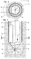
- Fig. 1
- einen Längsschnitt durch einen in einem Bohrkanal angeordneten Erdverdrängungsbohrer;
- Fig. 2
- einen Schnitt entlang der Linie II-II von Fig. 1;
- Fig. 3a und 3b
- eine dem Detail III von Fig. 2 entsprechende Schnittansicht zweier verschiedener Ausführungsformen; und
- Fig. 4
- eine Seitenansicht des Bohrkopfes von Fig. 1.
- Fig. 1
- a longitudinal section through an arranged in a drill hole Erdverdrängungsbohrer;
- Fig. 2
- a section along the line II-II of Fig. 1;
- Fig. 3a and 3b
- a detail III of Figure 2 corresponding sectional view of two different embodiments. and
- Fig. 4
- a side view of the drill head of Fig. 1st
Der in Fig. 1 dargestellte Erdverdrängungsbohrer weist ein kreiszylindrisches Bohrrohr 10 auf, an dessen unterem Ende ein Bohrkopf 12 angeschweißt ist. Der in Fig.4 vergrößert dargestellte Bohrkopf 12 weist an seinem rückwärtigen Ende einen kreisringförmigen Schaftabschnitt 14 auf, in den das vorderseitige Ende des Bohrrohres 10 gesteckt wird, woraufhin dann Bohrrohr 10 und Bohrkopf 12 mittels einer Schweißverbindung 16 miteinander verbunden werden können.The Erdverdrängungsbohrer shown in Fig. 1 has a circular
An den Schaftabschnitt 14 schließt sich ein konusförmiger Spitzenabschnitt 18 an, der mit dem Schaftabschnitt 14 einstückig ausgebildet ist. Sowohl im Bereich des Schaftabschnitts 14 wie auch des Spitzenabschnittes 18 sind mehrere wendelförmige Rippen 20, 21, 22 und 23 vorgesehen, wobei die Rippen 20 und 21 radial vom Schaftabschnitt 14 vorstehen und die Rippen 22 und 23 in Axialrichtung von dem Spitzenabschnitt 18 vorstehen. An sämtlichen Rippen sind voneinander beabstandete Zähne 24 vorgesehen, die in Axialrichtung des Bohrkopfes 12 weisen, die mit der Bohrrichtung X (Fig. 1) übereinstimmt.The
Wie Fig. 1 zeigt, ist der gesamte Bohrkopf 12 einstückig ausgebildet. Der Bohrkopf 12 wie auch das Bohrrohr 10 bestehen aus Stahl.As shown in FIG. 1, the
Wie Fig. 1 ferner verdeutlicht, ist der Radius des Bohrrohres 10 kleiner als der größte Radius des Bohrkopfes 12, so dass beim Eindrehen des Erdverdrängungsbohrers in Bodenmaterial zwischen dem entstandenen Bohrkanal und dem Bohrrohr 10 ein Ringraum 30 entsteht. Fig. 1 verdeutlicht ferner, dass sowohl das im Bereich des Bohrkopfes 12 entstehende Bohrloch 32 wie auch der Ringkanal 30 mit einem Gemenge aus Bohrfluid und Partikeln des Bodenmaterials gefüllt sind. Das Bohrfluid wird über eine im Inneren des Bohrrohres 10 angeordnete Rohrleitung 34 in den Bereich des vordersten Endes des Bohrkopfes 12 geführt und tritt von dort über radiale Austrittskanäle 36 in das Bohrloch 32 aus. Das austretende Bohrfluid 38 vermengt sich mit Partikeln des Bodenmaterials und füllt das Bohrloch 32 wie auch den Bohrkanal 30.1 further clarifies, the radius of the
Am Außenumfang des Bohrrohres 10 ist unmittelbar oberhalb des Bohrkopfes 12 ein Mischelement 40 vorgesehen, das sich in Längsrichtung X des Bohrrohres erstreckt und das radial nicht über den Bohrkopf 12 vorsteht, sondern sich radial nach außen etwa bis zum größten Radius des Bohrkopfes 12 erstreckt. Bei dem in den Fig. 1, 2 und 3a dargestellten Ausführungsbeispiel ist das Mischelement 40 ein rinnenförmiges Bauteil, dessen Radius kleiner als derjenige des Bohrrohres 10 ist. Das Mischelement 40 ist bei dem dargestellten Ausführungsbeispiel an den Außenmantel des Bohrrohres 10 geschweißt und an seiner Oberseite wie auch Unterseite geschlossen, so dass zwischen dem Mischelement 40 und dem Bohrrohr 10 ein geschlossenes Volumen eingeschlossen ist.On the outer circumference of the
Fig. 3b zeigt eine weitere Ausführungsform eines Mischelementes 40'. Bei diesem Ausführungsbeispiel ist das Mischelement 40' durch ein winkelförmiges Bauteil gebildet, dessen beide Schenkel gleich lang sind und einen Winkel von etwa 115° miteinander einschließen. Die Position des Mischelementes 40' an dem Bohrrohr 10 ist die gleiche wie die des Mischelementes 40.Fig. 3b shows another embodiment of a mixing element 40 '. In this embodiment, the mixing element 40 'is formed by an angle-shaped component, whose two legs are the same length and enclose an angle of about 115 ° with each other. The position of the mixing element 40 'on the
Wie die Fig. 3a und 3b verdeutlichen, kann das erfindungsgemäße Mischelement entweder eine konvexe Außenmantelfläche aufweisen (Fig. 3a) oder das Mischelement kann zwei aufeinander zulaufende Außenflächen besitzen (Fig. 3b). In beiden Fällen besitzt das Mischelement an seiner Außenseite eine Fläche 42 bzw. 42', die annähernd tangential zu dem Außenmantel des Bohrrohres 10 verläuft, und die als Keilfläche dient, da sie mit der Wand des von dem Bohrkopf gebildeten Bohrkanals 30 einen sich verjüngenden Bereich 44 bildet. Durch diese Keilflächen wird bei einer Rotation des Erdverdrängungsbohrers das aus Bohrfluid und Bodenmaterial bestehende Gemenge einerseits im Ringraum 30 vermischt und andererseits in die Wand des Bohrkanals eingetragen, so dass diese stabilisiert wird, was nachfolgend näher beschrieben wird.As FIGS. 3 a and 3 b illustrate, the mixing element according to the invention can either have a convex outer circumferential surface (FIG. 3 a) or the mixing element can have two outer surfaces converging towards one another (FIG. 3 b). In both cases, the mixing element has on its outer side a
Zum Erstellen eines Bohrloches mit dem oben beschriebenen Erdverdrängungsbohrer wird dieser in Richtung X in den Boden abgesenkt und dabei in Pfeilrichtung gedreht (Fig. 2 und 3). Gleichzeitig wird Bohrfluid 38 durch eine (nicht dargestellte) Pumpanordnung durch die Rohrleitung 34 geführt, so dass dieses aus dem Austrittskanal 36 an der Spitze des Bohrkopfes 12 in das Bohrloch 32 austritt. Die Form des mit den Zähnen 24 versehenen Bohrkopfes 12 sorgt dafür, dass sich das Bohrfluid 38 bereits etwas mit Teilen des Bodenmaterials vermischt.To create a borehole with the above-described Erdverdrängungsbohrer this is lowered in the X direction in the ground and thereby rotated in the arrow direction (Fig. 2 and 3). At the same time, drilling fluid 38 is passed through the
Bei weiter fortschreitendem Bohrvorgang füllt sich auch der Ringraum 30 oberhalb des Bohrkopfes 12, wobei in diesem Bereich das Mischelement 40 für eine innige Vermischung von Bohrfluid und Bodenmaterial sorgt. Gleichzeitig sorgt das Mischelement 40 dafür, dass das im Ringraum 30 befindliche Gemenge in die Wand des Bohrkanals eingepresst bzw. eingetragen wird, indem die Keilfläche 42 das im Bereich 44 befindliche Gemenge in die Wand des Bohrkanals einstreicht. Hierdurch werden die im umgebenden Bodenmaterial vorhandenen Poren 46 versiegelt und die Wand des Ringraums 30 bzw. des Bohrkanals wird sozusagen verputzt und dadurch versiegelt und stabilisiert. Insbesondere bei Verwendung entsprechender Zuschlagstoffe wird besonders gut erreicht, dass der Bohrkanal einen stabilisierten Wandabschnitt 48 aufweist, der gleichzeitig das umgebende Bodenmaterial versiegelt, so dass der Ringraum oberhalb des Bohrkopfes 12 mit Bohrfluid gefüllt bleibt, ohne dass dieses in den umgebenden Boden eindringt und versickert. Hierdurch ist einerseits sichergestellt, dass der Bohrkanal stabil bleibt und nicht zusammenfällt. Andererseits ist gewährleistet, dass die reibungsreduzierende Wirkung des Bohrfluides über die gesamte Länge des Bohrrohres aufrechterhalten bleibt, wodurch das zum Bohren erforderliche Drehmoment erheblich reduziert ist. Gleichzeitig kann die Wanddicke des Bohrrohres 12 innerhalb vernünftiger Grenzen bleiben.As the drilling progresses, so does the
Durch das Mischelement 40, 40' ist ferner eine gewisse Unwucht vorhanden, die dem Bohrer eine gewisse Schlingerbewegung auferlegt, die sich beim Bohren positiv auswirkt.By the mixing
Insbesondere für größere Rohrdurchmesser können auch mehrere Mischelemente 40 bzw. 40' vorgesehen werden. Auch kann das Mischelement schräg am Außenumfang des Bohrrohres angeordnet werden. Weiterhin können sowohl Bohrrohr wie auch Mischelement auch aus Kunststoff bestehen. Auch kann das Mischelement in Axialrichtung gekrümmt oder geschwungen ausgebildet sein. Weiterhin ist es nicht unbedingt erforderlich, dass das Bohrfluid durch das Innere des Bohrkopfes in das Bohrloch 32 injiziert wird. Dies könnte auch durch den Ringraum 30 erfolgen.In particular, for larger pipe diameters, a plurality of mixing
- 1010
- Bohrrohrdrill pipe
- 1212
- Bohrkopfwellhead
- 1414
- Schaftabschnittshank portion
- 1616
- SchweißnahtWeld
- 1818
- Spitzenabschnitttip portion
- 2021,22,232021,22,23
- Rippenribs
- 2424
- Zähneteeth
- 3030
- Ringraumannulus
- 3232
- Bohrlochwell
- 3434
- Rohrleitungpipeline
- 3636
- Austrittskanaloutlet channel
- 3838
- Bohrfluiddrilling fluid
- 40, 40'40, 40 '
- Mischelementmixing element
- 42, 42'42, 42 '
- Keilflächewedge surface
- 4444
- verjüngender Bereichrejuvenating area
- 4646
- Porenpore
- 4848
- stabilisierter Wandabschnittstabilized wall section
Claims (15)
- An earth displacement drill comprising a drill tube (10) and a drill head (12) non-releasably fastened to its end, wherein the radius of the drill tube (10) is smaller than the largest radius of the drill head (12), and wherein at least one mixing element (40, 40') extending in the longitudinal direction (X) of the drill tube (10) is provided at the outer periphery thereof,
characterized in that
the drill tube (10) extends in a straight line up to the drill head (12); in that the mixing element (40, 40') is rigidly fastened to the outer periphery of the drill tube (10); and in that at least one radially projecting, spiral-shaped rib (20, 21) is provided. - An earth displacement drill in accordance with claim 1, characterized in that the mixing element (40, 40') does not project radially beyond the drill head (12) and in particular extends radially outwardly approximately up to the largest radius of the drill head.
- An earth displacement drill in accordance with claim 1, characterized in that the mixing element (40, 40') is arranged directly above the drill head (12).
- An earth displacement drill in accordance with claim 1, characterized in that the mixing element (40, 40') includes a volume between it and the drill tube (10) which is particular a closed volume.
- An earth displacement drill in accordance with claim 1, characterized in that the mixing element (40, 40') is made symmetrical in longitudinal section and/or in cross-section.
- An earth displacement drill in accordance with claim 1, characterized in that the mixing element (40 40') has at least one wedge surface (42, 42') which, when viewed in cross-section, forms a converging region (44) with the wall (48) of a drill channel formed by the drill head.
- An earth displacement drill in accordance with claim 1, characterized in that the mixing element (40) has a convex outer surface.
- An earth displacement drill in accordance with claim 1, characterized in that the mixing element (40, 40') has at least one outer surface extending approximately tangentially to the drill tube (10).
- An earth displacement drill in accordance with claim 1, characterized in that a plane extending through the central axis (X) of the drill tube forms an angle with the longitudinal axis of the mixing element.
- An earth displacement drill in accordance with claim 1, characterized in that the longitudinal extent of the mixing element (40, 40') amounts to approximately 150 - 250% of the drill tube diameter.
- An earth displacement drill in accordance with claim 1, characterized in that the drill head (12) has at least one axially projecting rib (20 - 23) at whose lower side individual teeth (24) are provided which extend in the drilling direction (X).
- An earth displacement drill in accordance with claim 1, characterized in that the radially projecting rib (20, 21) has individual teeth (24) at its lower side which extend in the drilling direction (X).
- A method of preparing a bore using an earth displacement drill in accordance with at least one of the preceding claims, wherein the earth displacement drill is bored into the subsurface, a drill fluid is introduced into the ring space arising between the bore and the drill channel and this drill fluid is mixed above the drill head.
- A method in accordance with claim 13, characterized in that the drill fluid is additionally introduced, in particular pressed, into the wall of the drill channel.
- A method in accordance with claim 13, characterized in that the drill fluid is guided through the drill tube and the drill head into the bore.
Priority Applications (3)
| Application Number | Priority Date | Filing Date | Title |
|---|---|---|---|
| AT04003435T ATE338195T1 (en) | 2004-02-16 | 2004-02-16 | EARTH DISPLACEMENT DRILL |
| DE502004001336T DE502004001336D1 (en) | 2004-02-16 | 2004-02-16 | Earth displacement drill |
| EP04003435A EP1564367B1 (en) | 2004-02-16 | 2004-02-16 | Earth displacement drill |
Applications Claiming Priority (1)
| Application Number | Priority Date | Filing Date | Title |
|---|---|---|---|
| EP04003435A EP1564367B1 (en) | 2004-02-16 | 2004-02-16 | Earth displacement drill |
Publications (2)
| Publication Number | Publication Date |
|---|---|
| EP1564367A1 EP1564367A1 (en) | 2005-08-17 |
| EP1564367B1 true EP1564367B1 (en) | 2006-08-30 |
Family
ID=34684703
Family Applications (1)
| Application Number | Title | Priority Date | Filing Date |
|---|---|---|---|
| EP04003435A Expired - Lifetime EP1564367B1 (en) | 2004-02-16 | 2004-02-16 | Earth displacement drill |
Country Status (3)
| Country | Link |
|---|---|
| EP (1) | EP1564367B1 (en) |
| AT (1) | ATE338195T1 (en) |
| DE (1) | DE502004001336D1 (en) |
Families Citing this family (2)
| Publication number | Priority date | Publication date | Assignee | Title |
|---|---|---|---|---|
| DE502007001500D1 (en) * | 2007-07-06 | 2009-10-22 | Bauer Maschinen Gmbh | auger |
| BE1023794B1 (en) | 2016-07-14 | 2017-07-26 | Proferro Nv | A TIP WITH PROJECTS FOR A GROUND-MOUNTING OPERATION FOR A FOUNDATION POLE |
Family Cites Families (9)
| Publication number | Priority date | Publication date | Assignee | Title |
|---|---|---|---|---|
| US3255833A (en) * | 1963-10-10 | 1966-06-14 | Texaco Development Corp | Drill bit auxiliary |
| US3799279A (en) * | 1972-09-25 | 1974-03-26 | R Farris | Optionally stabilized drilling tool |
| DE19530718C1 (en) * | 1995-08-21 | 1996-09-26 | Bauer Spezialtiefbau | Boring device and method for producing concrete post in bore hole |
| AUPO114996A0 (en) * | 1996-07-22 | 1996-08-15 | Jarmyn, Gary Wayne | Identification and warning system for underground conduits or pipes laid by the 'directional drilling' method |
| DE19749409A1 (en) * | 1997-05-04 | 1999-05-12 | Gerd Hoermansdoerfer | Special drilling process and corresponding drill head |
| DE19859928C1 (en) * | 1998-12-23 | 2000-08-31 | Ludwig Pfeiffer Hoch Und Tiefb | Process and protective tube for renewing a pipeline laid in the ground |
| GB2365463B (en) * | 2000-08-01 | 2005-02-16 | Renovus Ltd | Drilling method |
| DE10150278B4 (en) * | 2001-10-12 | 2006-07-06 | Tracto-Technik Gmbh | Method and device for soil stabilization |
| DE10205826A1 (en) * | 2001-10-18 | 2003-05-08 | Fitr Ges Fuer Innovation Im Ti | Laying a buried pipe uses a flow of a suspension to reduce friction, to be mixed with the displaced ground spoil, to form a seal in the ring gap around the pipe wall in the ground |
-
2004
- 2004-02-16 AT AT04003435T patent/ATE338195T1/en not_active IP Right Cessation
- 2004-02-16 EP EP04003435A patent/EP1564367B1/en not_active Expired - Lifetime
- 2004-02-16 DE DE502004001336T patent/DE502004001336D1/en not_active Expired - Fee Related
Also Published As
| Publication number | Publication date |
|---|---|
| ATE338195T1 (en) | 2006-09-15 |
| EP1564367A1 (en) | 2005-08-17 |
| DE502004001336D1 (en) | 2006-10-12 |
Similar Documents
| Publication | Publication Date | Title |
|---|---|---|
| DE10017763B4 (en) | rock bolts | |
| DE2941769C2 (en) | Procedure for setting an anchor bolt and anchor bolts | |
| EP2257690B1 (en) | Corrosion-protected self-drilling anchor and anchor subunit and method for the production thereof | |
| EP0588143B1 (en) | Earth drill for placing a concrete pile in situ | |
| EP0371463B1 (en) | Method for installing an anchor and injection drill anchoring for performing the method | |
| DE102013111350A1 (en) | Expander tool and device for expanding a passage opening present in the ground | |
| EP0355379A2 (en) | Drilling-injection anchor | |
| DE102011085187B3 (en) | Drill and manufacturing process for a drill | |
| EP0368838B1 (en) | Device for the consolidation of geological formations having no or only little stability | |
| DE3624202C2 (en) | Twist drill | |
| DE3738420C2 (en) | ||
| DE2422489C2 (en) | Earth drill and method for inserting piles or the like. | |
| EP1564367B1 (en) | Earth displacement drill | |
| DE2343080A1 (en) | DRILLING METHOD AND DEVICE FOR ITS IMPLEMENTATION | |
| EP2065559A2 (en) | Self-boring compound anchoring element | |
| DE102011077595A1 (en) | anchor bolt | |
| WO2019086164A1 (en) | Auger arrangement | |
| EP3112580B1 (en) | Method and device for forming an underground pipeline | |
| CH693934A5 (en) | Method for earth and rock anchor bore drilling uses drill crown to which drill pipe is attached to define annular space for evacuation of hardened material | |
| DE2711899A1 (en) | DEVICE FOR SOIL INJECTION IN HIGH PRESSURE SOIL AND PILE FOUNDATIONS | |
| DE19744322C1 (en) | Method of placing anchor piles in friable soils | |
| DE3737259C1 (en) | Apparatus and method for high-pressure injection | |
| DE19503177C1 (en) | Method of mfr. of concrete posts submerged in ground | |
| DE102004005238B3 (en) | Device for producing holes in the ground for anchoring and posts comprises an endless screw having several helix cutouts arranged in a part of the screw helix surfaces arranged behind the crown | |
| DE728403C (en) | Device for flushing the drilling rig |
Legal Events
| Date | Code | Title | Description |
|---|---|---|---|
| PUAI | Public reference made under article 153(3) epc to a published international application that has entered the european phase |
Free format text: ORIGINAL CODE: 0009012 |
|
| 17P | Request for examination filed |
Effective date: 20050530 |
|
| AK | Designated contracting states |
Kind code of ref document: A1 Designated state(s): AT BE BG CH CY CZ DE DK EE ES FI FR GB GR HU IE IT LI LU MC NL PT RO SE SI SK TR |
|
| AX | Request for extension of the european patent |
Extension state: AL LT LV MK |
|
| GRAP | Despatch of communication of intention to grant a patent |
Free format text: ORIGINAL CODE: EPIDOSNIGR1 |
|
| AKX | Designation fees paid |
Designated state(s): AT BE BG CH CY CZ DE DK EE ES FI FR GB GR HU IE IT LI LU MC NL PT RO SE SI SK TR |
|
| AXX | Extension fees paid |
Extension state: LT Payment date: 20050530 |
|
| GRAS | Grant fee paid |
Free format text: ORIGINAL CODE: EPIDOSNIGR3 |
|
| GRAA | (expected) grant |
Free format text: ORIGINAL CODE: 0009210 |
|
| AK | Designated contracting states |
Kind code of ref document: B1 Designated state(s): AT BE BG CH CY CZ DE DK EE ES FI FR GB GR HU IE IT LI LU MC NL PT RO SE SI SK TR |
|
| AX | Request for extension of the european patent |
Extension state: LT |
|
| PG25 | Lapsed in a contracting state [announced via postgrant information from national office to epo] |
Ref country code: GB Free format text: LAPSE BECAUSE OF FAILURE TO SUBMIT A TRANSLATION OF THE DESCRIPTION OR TO PAY THE FEE WITHIN THE PRESCRIBED TIME-LIMIT Effective date: 20060830 Ref country code: CZ Free format text: LAPSE BECAUSE OF FAILURE TO SUBMIT A TRANSLATION OF THE DESCRIPTION OR TO PAY THE FEE WITHIN THE PRESCRIBED TIME-LIMIT Effective date: 20060830 Ref country code: IE Free format text: LAPSE BECAUSE OF FAILURE TO SUBMIT A TRANSLATION OF THE DESCRIPTION OR TO PAY THE FEE WITHIN THE PRESCRIBED TIME-LIMIT Effective date: 20060830 Ref country code: SK Free format text: LAPSE BECAUSE OF FAILURE TO SUBMIT A TRANSLATION OF THE DESCRIPTION OR TO PAY THE FEE WITHIN THE PRESCRIBED TIME-LIMIT Effective date: 20060830 Ref country code: FI Free format text: LAPSE BECAUSE OF FAILURE TO SUBMIT A TRANSLATION OF THE DESCRIPTION OR TO PAY THE FEE WITHIN THE PRESCRIBED TIME-LIMIT Effective date: 20060830 Ref country code: SI Free format text: LAPSE BECAUSE OF FAILURE TO SUBMIT A TRANSLATION OF THE DESCRIPTION OR TO PAY THE FEE WITHIN THE PRESCRIBED TIME-LIMIT Effective date: 20060830 Ref country code: RO Free format text: LAPSE BECAUSE OF FAILURE TO SUBMIT A TRANSLATION OF THE DESCRIPTION OR TO PAY THE FEE WITHIN THE PRESCRIBED TIME-LIMIT Effective date: 20060830 Ref country code: IT Free format text: LAPSE BECAUSE OF FAILURE TO SUBMIT A TRANSLATION OF THE DESCRIPTION OR TO PAY THE FEE WITHIN THE PRE;WARNING: LAPSES OF ITALIAN PATENTS WITH EFFECTIVE DATE BEFORE 2007 MAY HAVE OCCURRED AT ANY TIME BEFORE 2007. THE CORRECT EFFECTIVE DATE MAY BE DIFFERENT FROM THE ONE RECORDED.SCRIBED TIME-LIMIT Effective date: 20060830 |
|
| REG | Reference to a national code |
Ref country code: GB Ref legal event code: FG4D Free format text: NOT ENGLISH |
|
| REG | Reference to a national code |
Ref country code: CH Ref legal event code: EP |
|
| REG | Reference to a national code |
Ref country code: IE Ref legal event code: FG4D Free format text: LANGUAGE OF EP DOCUMENT: GERMAN |
|
| REF | Corresponds to: |
Ref document number: 502004001336 Country of ref document: DE Date of ref document: 20061012 Kind code of ref document: P |
|
| PG25 | Lapsed in a contracting state [announced via postgrant information from national office to epo] |
Ref country code: DK Free format text: LAPSE BECAUSE OF FAILURE TO SUBMIT A TRANSLATION OF THE DESCRIPTION OR TO PAY THE FEE WITHIN THE PRESCRIBED TIME-LIMIT Effective date: 20061130 Ref country code: BG Free format text: LAPSE BECAUSE OF FAILURE TO SUBMIT A TRANSLATION OF THE DESCRIPTION OR TO PAY THE FEE WITHIN THE PRESCRIBED TIME-LIMIT Effective date: 20061130 Ref country code: SE Free format text: LAPSE BECAUSE OF FAILURE TO SUBMIT A TRANSLATION OF THE DESCRIPTION OR TO PAY THE FEE WITHIN THE PRESCRIBED TIME-LIMIT Effective date: 20061130 |
|
| PG25 | Lapsed in a contracting state [announced via postgrant information from national office to epo] |
Ref country code: ES Free format text: LAPSE BECAUSE OF FAILURE TO SUBMIT A TRANSLATION OF THE DESCRIPTION OR TO PAY THE FEE WITHIN THE PRESCRIBED TIME-LIMIT Effective date: 20061211 |
|
| PG25 | Lapsed in a contracting state [announced via postgrant information from national office to epo] |
Ref country code: PT Free format text: LAPSE BECAUSE OF FAILURE TO SUBMIT A TRANSLATION OF THE DESCRIPTION OR TO PAY THE FEE WITHIN THE PRESCRIBED TIME-LIMIT Effective date: 20070206 |
|
| LTIE | Lt: invalidation of european patent or patent extension |
Effective date: 20060830 |
|
| PG25 | Lapsed in a contracting state [announced via postgrant information from national office to epo] |
Ref country code: MC Free format text: LAPSE BECAUSE OF NON-PAYMENT OF DUE FEES Effective date: 20070228 |
|
| ET | Fr: translation filed | ||
| GBV | Gb: ep patent (uk) treated as always having been void in accordance with gb section 77(7)/1977 [no translation filed] |
Effective date: 20060830 |
|
| REG | Reference to a national code |
Ref country code: IE Ref legal event code: FD4D |
|
| PLBE | No opposition filed within time limit |
Free format text: ORIGINAL CODE: 0009261 |
|
| STAA | Information on the status of an ep patent application or granted ep patent |
Free format text: STATUS: NO OPPOSITION FILED WITHIN TIME LIMIT |
|
| 26N | No opposition filed |
Effective date: 20070531 |
|
| PG25 | Lapsed in a contracting state [announced via postgrant information from national office to epo] |
Ref country code: GR Free format text: LAPSE BECAUSE OF FAILURE TO SUBMIT A TRANSLATION OF THE DESCRIPTION OR TO PAY THE FEE WITHIN THE PRESCRIBED TIME-LIMIT Effective date: 20061201 |
|
| PGFP | Annual fee paid to national office [announced via postgrant information from national office to epo] |
Ref country code: FR Payment date: 20070212 Year of fee payment: 4 |
|
| PG25 | Lapsed in a contracting state [announced via postgrant information from national office to epo] |
Ref country code: AT Free format text: LAPSE BECAUSE OF NON-PAYMENT OF DUE FEES Effective date: 20070216 |
|
| PG25 | Lapsed in a contracting state [announced via postgrant information from national office to epo] |
Ref country code: EE Free format text: LAPSE BECAUSE OF FAILURE TO SUBMIT A TRANSLATION OF THE DESCRIPTION OR TO PAY THE FEE WITHIN THE PRESCRIBED TIME-LIMIT Effective date: 20060830 |
|
| REG | Reference to a national code |
Ref country code: FR Ref legal event code: ST Effective date: 20081031 |
|
| PG25 | Lapsed in a contracting state [announced via postgrant information from national office to epo] |
Ref country code: FR Free format text: LAPSE BECAUSE OF NON-PAYMENT OF DUE FEES Effective date: 20080229 |
|
| PG25 | Lapsed in a contracting state [announced via postgrant information from national office to epo] |
Ref country code: LU Free format text: LAPSE BECAUSE OF NON-PAYMENT OF DUE FEES Effective date: 20070216 Ref country code: CY Free format text: LAPSE BECAUSE OF FAILURE TO SUBMIT A TRANSLATION OF THE DESCRIPTION OR TO PAY THE FEE WITHIN THE PRESCRIBED TIME-LIMIT Effective date: 20060830 |
|
| PG25 | Lapsed in a contracting state [announced via postgrant information from national office to epo] |
Ref country code: HU Free format text: LAPSE BECAUSE OF FAILURE TO SUBMIT A TRANSLATION OF THE DESCRIPTION OR TO PAY THE FEE WITHIN THE PRESCRIBED TIME-LIMIT Effective date: 20070301 Ref country code: TR Free format text: LAPSE BECAUSE OF FAILURE TO SUBMIT A TRANSLATION OF THE DESCRIPTION OR TO PAY THE FEE WITHIN THE PRESCRIBED TIME-LIMIT Effective date: 20060830 |
|
| PGFP | Annual fee paid to national office [announced via postgrant information from national office to epo] |
Ref country code: CH Payment date: 20090528 Year of fee payment: 6 |
|
| PGFP | Annual fee paid to national office [announced via postgrant information from national office to epo] |
Ref country code: DE Payment date: 20090529 Year of fee payment: 6 |
|
| REG | Reference to a national code |
Ref country code: CH Ref legal event code: PL |
|
| PG25 | Lapsed in a contracting state [announced via postgrant information from national office to epo] |
Ref country code: CH Free format text: LAPSE BECAUSE OF NON-PAYMENT OF DUE FEES Effective date: 20100228 Ref country code: LI Free format text: LAPSE BECAUSE OF NON-PAYMENT OF DUE FEES Effective date: 20100228 |
|
| PG25 | Lapsed in a contracting state [announced via postgrant information from national office to epo] |
Ref country code: DE Free format text: LAPSE BECAUSE OF NON-PAYMENT OF DUE FEES Effective date: 20100901 |
|
| PGFP | Annual fee paid to national office [announced via postgrant information from national office to epo] |
Ref country code: NL Payment date: 20110216 Year of fee payment: 8 |
|
| PGFP | Annual fee paid to national office [announced via postgrant information from national office to epo] |
Ref country code: BE Payment date: 20110211 Year of fee payment: 8 |
|
| BERE | Be: lapsed |
Owner name: BEHEERSMAATSCHAPPIJ *VERSTRAETEN B.V. Effective date: 20120228 |
|
| REG | Reference to a national code |
Ref country code: NL Ref legal event code: V1 Effective date: 20120901 |
|
| PG25 | Lapsed in a contracting state [announced via postgrant information from national office to epo] |
Ref country code: BE Free format text: LAPSE BECAUSE OF NON-PAYMENT OF DUE FEES Effective date: 20120228 |
|
| PG25 | Lapsed in a contracting state [announced via postgrant information from national office to epo] |
Ref country code: NL Free format text: LAPSE BECAUSE OF NON-PAYMENT OF DUE FEES Effective date: 20120901 |