EP1564115A2 - Fender assembly and mounting clamp therefor - Google Patents
Fender assembly and mounting clamp therefor Download PDFInfo
- Publication number
- EP1564115A2 EP1564115A2 EP05002962A EP05002962A EP1564115A2 EP 1564115 A2 EP1564115 A2 EP 1564115A2 EP 05002962 A EP05002962 A EP 05002962A EP 05002962 A EP05002962 A EP 05002962A EP 1564115 A2 EP1564115 A2 EP 1564115A2
- Authority
- EP
- European Patent Office
- Prior art keywords
- fender
- mounting
- clamps
- assembly according
- vehicle
- Prior art date
- Legal status (The legal status is an assumption and is not a legal conclusion. Google has not performed a legal analysis and makes no representation as to the accuracy of the status listed.)
- Granted
Links
- 230000013011 mating Effects 0.000 claims abstract description 9
- 230000000295 complement effect Effects 0.000 claims description 19
- 239000000088 plastic resin Substances 0.000 claims description 9
- 239000004677 Nylon Substances 0.000 claims description 5
- 230000004075 alteration Effects 0.000 claims description 5
- 229920001778 nylon Polymers 0.000 claims description 5
- 239000004743 Polypropylene Substances 0.000 claims description 4
- 239000011152 fibreglass Substances 0.000 claims description 4
- -1 polypropylene Polymers 0.000 claims description 4
- 229920001155 polypropylene Polymers 0.000 claims description 4
- 229910052751 metal Inorganic materials 0.000 claims description 2
- 239000002184 metal Substances 0.000 claims description 2
- 230000008878 coupling Effects 0.000 abstract 1
- 238000010168 coupling process Methods 0.000 abstract 1
- 238000005859 coupling reaction Methods 0.000 abstract 1
- 230000000712 assembly Effects 0.000 description 7
- 238000000429 assembly Methods 0.000 description 7
- 238000000034 method Methods 0.000 description 4
- 210000000887 face Anatomy 0.000 description 3
- 238000002347 injection Methods 0.000 description 3
- 239000007924 injection Substances 0.000 description 3
- 239000000463 material Substances 0.000 description 3
- 238000003466 welding Methods 0.000 description 3
- 230000007812 deficiency Effects 0.000 description 2
- 238000005553 drilling Methods 0.000 description 2
- 238000007373 indentation Methods 0.000 description 2
- 239000000126 substance Substances 0.000 description 2
- 239000000057 synthetic resin Substances 0.000 description 2
- 229920003002 synthetic resin Polymers 0.000 description 2
- 229910000831 Steel Inorganic materials 0.000 description 1
- 229910052782 aluminium Inorganic materials 0.000 description 1
- XAGFODPZIPBFFR-UHFFFAOYSA-N aluminium Chemical compound [Al] XAGFODPZIPBFFR-UHFFFAOYSA-N 0.000 description 1
- 229910000078 germane Inorganic materials 0.000 description 1
- 238000011900 installation process Methods 0.000 description 1
- 230000003993 interaction Effects 0.000 description 1
- 238000005058 metal casting Methods 0.000 description 1
- 230000004048 modification Effects 0.000 description 1
- 238000012986 modification Methods 0.000 description 1
- 239000011347 resin Substances 0.000 description 1
- 229920005989 resin Polymers 0.000 description 1
- 238000005476 soldering Methods 0.000 description 1
- 229910001220 stainless steel Inorganic materials 0.000 description 1
- 239000010935 stainless steel Substances 0.000 description 1
- 239000010959 steel Substances 0.000 description 1
- 229920001169 thermoplastic Polymers 0.000 description 1
- 229920005992 thermoplastic resin Polymers 0.000 description 1
- 239000004416 thermosoftening plastic Substances 0.000 description 1
Images


Classifications
-
- B—PERFORMING OPERATIONS; TRANSPORTING
- B62—LAND VEHICLES FOR TRAVELLING OTHERWISE THAN ON RAILS
- B62D—MOTOR VEHICLES; TRAILERS
- B62D25/00—Superstructure or monocoque structure sub-units; Parts or details thereof not otherwise provided for
- B62D25/08—Front or rear portions
- B62D25/16—Mud-guards or wings; Wheel cover panels
- B62D25/18—Parts or details thereof, e.g. mudguard flaps
-
- B—PERFORMING OPERATIONS; TRANSPORTING
- B62—LAND VEHICLES FOR TRAVELLING OTHERWISE THAN ON RAILS
- B62D—MOTOR VEHICLES; TRAILERS
- B62D25/00—Superstructure or monocoque structure sub-units; Parts or details thereof not otherwise provided for
- B62D25/08—Front or rear portions
- B62D25/16—Mud-guards or wings; Wheel cover panels
- B62D25/168—Mud guards for utility vehicles
Definitions
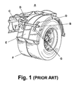
- fender assemblies A comprise a mounting arm B that extends laterally from the vehicle frame C, mounting brackets D, and a fender E.
- the mounting brackets D are fixed to the fender E and receive the mounting arm B.
- the mounting arm B bears a preponderance of the weight of the fender E and maintains the fender E in a desirable position above the drive wheels F.
- the mounting arm B can be fixed or rotatably mounted to the vehicle frame C.
- the fender assembly A is rotationally adjustable relative to the vehicle frame C.
- the other end of the mounting arm B is secured to the fender E by the mounting brackets D.
- the mounting brackets D are secured to the fender E by traditional mechanical fasteners, which are shown as bolts G, that extend through the fender E.
- mechanical fasteners which are shown as bolts G
- bolts G that extend through the fender E.
- These and other conventional mechanical means typically require permanent alteration of the fender.
- the mounting arm, the mounting brackets, and the fender are aligned relative to each other and to the vehicle frame, holes are drilled through the fender in locations to accomplish the desired alignment, and then the bolts or other mechanical fasteners are inserted through the mounting brackets and the holes in the fender. Because this process is very labor intensive and the working area near the vehicle frame is usually limited, it is often difficult to accurately mount the fender in the desired position.
- the fender is placed in proper location with respect to the wheels. This location is critical and cannot be altered. Then, the mounting arm B is mounted to the frame and the position of the mounting brackets on the fender is observed and the hole locations are marked. Often, there is very limited maneuvering room for the mounting arm and there is not much room to adjust the position of the mounting arm B with respect to the fender. If the holes are drilled in incorrect locations, the fender can be improperly positioned or the mounting brackets D might not align with the holes. Frequently, the fender must be marked again and new holes drilled in the fender. Other means of fixing the mounting brackets to the fender include welding, soldering, or other chemical bonding means. While chemical bonding methods securely fix the mounting brackets to the fender, they permanently alter the fender and have deficiencies similar to those of mechanical fastening means, especially if the brackets are improperly mounted.
- U.S Patent No. 5,950,975 to Zieske discloses a fender mounting assembly comprising a fender mounting plate having traditional circular clamps for receiving a mounting arm.
- the clamps include bolts that can be tightened to securely grasp the arm, and the fender mounting plate is coupled to a lower surface of a fender.
- the arm can be directly attached to the fender by bolts and nuts.
- Another fender assembly is disclosed in U.S. Patent No. 4,591,178 to Mortvedt et al. (Mortvedt '178).
- U-shaped clamps sized to receive mounting tubes are secured to an upper surface of the fender with bolts that extend through the clamps and holes in the fender.
- U.S. Patent No. 4,377,294 to Lockwood et al. discloses a fender assembly comprising a mounting arm that sits within a support seat formed in an upper surface of the fender panel. Clamping plates are positioned inside the mounting arm and against the bottom surface of the fender panel. Threaded bolts extend through the clamping plates, the mounting arm, and the fender panel to securely couple the mounting arm to the fender panel. Additionally, U.S. Patent No.
- 1,094,134 to Dickerson discloses a fender assembly with a bent tubular arm having an inner horizontal portion and an outer horizontal portion that is received by brackets, which are positioned under the fender and fastened thereto with bolts.
- Fender bracing assemblies were commonly used on early passenger automobiles to hold fenders under tension and to lift fenders to their proper positions. Such assemblies commonly comprised a rod or wire that connects clamps or brackets coupled to fenders on both sides of the automobile. The clamps typically wrap around the edges of the fenders and include means for retaining the rod or wire.
- U.S. Patent No. 1,489,062 to Burnam (Burnam '062) discloses a fender brace comprising a flexible wire cable disposed between two front fenders. A pair of bifurcated hook clamps, each having a hook portion and an eye portion, is mounted to each fender such that the hook portions wrap around the edges of the fenders.
- the wire cable is threaded through the eyes and secured in place with nuts and bolts.
- Similar braces are described in U.S. Patent No. 1,434,477 to Bury (Bury '477) and 1,511,813 to Dunn (Dunn '813).
- the clamps in the Bury '477 and the Dunn '813 devices are single-piece components that wrap around both the inside and outside edges of the fenders.
- Fender bracing assemblies differ from fender mounting assemblies in that the latter bear a preponderance of the fender weight while the former merely hold a pair of fenders under tension to prevent vibration and to assist in holding them above the automobile wheels.
- a fender assembly according to the preamble of claim 1 has a pair of mounting clamps that are adapted to adjustably mount to the fender for adjusting the relative position of the fender with respect to the mounting arm and thereby adjusting the position of the fender with respect to a vehicle when the one end of the mounting arm is attached to a vehicle frame.
- the mounting clamps are removably mounted to the fender without physically altering the fender.
- the mounting clamps are adapted to clamp the fender between them when the mounting clamps are mounted to the mounting arm. In another embodiment, at least one of the mounting clamps is adapted to releasably mount to the mounting arm.
- the fender has side edges and the mounting clamps have grooves that receive a portion of the side edges of the fender.
- the fender and the mounting clamps include complementary mating elements that lock the clamps and fender in an adjusted relationship.
- the complementary mating elements are in the form of serrations on the fender side edges and on the groove in the mounting clamps.
- the serrations can comprise channels and fingers and can have complementary sloped ridges between the channels and fingers on the fender side edges and the groove in the mounting clamps. The portions of the fender side edges that are received in the groove can form undercut pockets that receive a portion of the mounting clamps.
- the fender is integrally molded of a synthetic plastic resin, preferably, a high density polypropylene.
- the mounting clamps can be integrally molded of a synthetic plastic resin, preferably a fiberglass filled nylon.
- a bore is formed in the mounting clamps for receiving the mounting arm.
- a threaded aperture is provided in the mounting clamps transverse to and intersecting the bore, and a set screw in threaded apertures for releasably retaining the relative positions of the mounting clamps on the mounting arms.
- the threaded bore is formed in a metal T nut mounted in a through hole in the mounting clamps. The T nut has a lateral flange that is received in the bore.
- a mounting clamp for use in adjustably mounting a fender to a vehicle has an attachment part for releasably attaching the clamp to a mounting arm that is adapted to be attached to a vehicle and the mounting clamp has a groove that is adapted to receive a portion of side edges of the fender.
- Two such clamps can be positioned on opposing sides of a fender to releasably mount the fender to a mounting arm.
- the groove has a plurality of serrations for gripping the side edges of a fender.
- the serrations can be formed with channels and fingers.
- complementary sloped ridges can be formed between the channels and fingers on the groove.
- the mounting clamps are integrally molded of a synthetic plastic resin, preferably a fiberglass filled nylon.
- the serrations can comprise channels and fingers and further can include complementary sloped ridges between the channels and fingers.
- the fender is integrally molded of a synthetic plastic resin, preferably a high density polypropylene. Further, portions of the fender side edges can be formed with undercut pockets that are adapted to receive a portion of mounting clamps.
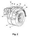
- a fender assembly 20 according to the invention comprises a fender 22, a pair of mounting clamps 24, and a mounting arm 26 that mounts the fender 22 to the vehicle frame 12. While the mounting arm 26 is illustrated as a straight rod, the mounting arm can have any suitable form, including a rotationally adjustable mounting arm. Mounting arms are well known and not germane to the invention; therefore, the mounting arm 26 will not be discussed in further detail.
- the fender 22 has a width slightly greater than that of the wheels 14 and is curved to overlie the wheels 14.
- the fender 22 is illustrated as a full single axis fender that extends through a 180-degree arc; however, it is within the scope of the invention for the fender 22 to be of any type or size.
- the fender 22 can be single-axis or tandem; full (180-degree), half (90-degree), or quarter (45-degree); and single or double-radius.
- the fender 22 comprises a panel 38 defined by parallel inner and outer edges 42, 44 and having a relatively flat upper surface 40 and a ribbed lower surface 46.
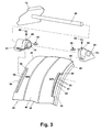
- the inner and outer edges 42, 44 include mount sections 50 adapted to mate with the mounting clamps 24.
- the mount sections 50 are arranged in a pair, wherein a first mounting section 50A is disposed along the inner edge 42 and a second mounting section 50B is located along the outer edge 44 directly across from the first mounting section 50A.
- Each mount section 50 has an undercut pocket 66 defined by the panel 38 that terminates in a lateral side edge 64, a lower wall 54 radially spaced from the panel 38 and integral with the fender side walls 48, and flanking walls 56. As best viewed in FIG. 4A, a plurality of sloped ridges 60 with channels 62 therebetween extend down from the lateral side edge 64 and towards the lower wall 54. Each sloped ridge 60 has a sloped face 61, as illustrated in FIG. 7.
- the length, or distance between the flanking walls 56, of each mount section 50 is preferably greater than the width of the mounting clamps 24. Consequently, the position of the mounting clamps 24 is adjustable within mount sections 50.
- the fender 22 can optionally comprise two circumferentially spaced pairs of mount sections 50. It should be apparent to one skilled in the art that the fender 22 can comprise any number of mount sections 50 located anywhere on the fender 22 for mounting the fender 22 to the vehicle 10. Each pair of mount sections 50 corresponds to its own pair of mounting clamps 24 and its own corresponding mounting arm 26. The number of mount sections 50 depends on factors such as the shape, size, and weight of the fender 22. For brevity, the description of the fender assembly 10 presented herein is limited to a single pair of mount sections 50.
- the fender can be made from a number of light weight, rigid materials, such as steel, aluminum and synthetic resin.
- the fenders are injection molded of a synthetic thermoplastic resin.
- the type of resin can vary, depending the desired properties.
- the fenders are injection molded from a high density polypropylene.
- each mounting clamp 24 comprises a base 70 with a curvature substantially equal to that of the fender panel 38 and a body 72 having a bore 74 therethrough sized to receive the mounting arm 26.
- the bore 72 has an indentation 82 at an upper portion of the outer end thereof.
- the base 70 and the body 72 are partially separated by a groove 76 sized to receive the inner or outer edge 42 or 44 of the fender panel 38.
- the base 70 comprises a plurality of fingers 78 disposed between sloped ridges 80 having sloped faces 81.
- the fingers 78 are sized for receipt within the fender channels 62, and the sloped ridges 80 are designed to mate with and complement the sloped ridges 60 on the fender 22 such that their respective sloped faces 81, 61 abut each other, as best viewed in FIG. 7. Additionally, the areas between the fingers 78 and above the sloped ridges 80 have a slight inward taper to facilitate an interference fit when the sloped ridges 60 are inserted therein.
- the body 72 protrudes forward of the base 70 and merges from a substantially planar wall 90, which partially defines the groove 76, into a generally cylindrical portion 92, which defines the bore 74.
- the cylindrical portion 92 comprises a collar 84 having a radial opening 86 for receiving a setscrew 88.
- An internally threaded T-nut is positioned in the indentation 82 and extends into the opening.
- the setscrew is threaded into the T-nut and extends out the bottom thereof for gripping contact with mounting arm 26.
- the cylindrical portion 92 further comprises, along a lower portion thereof, a lever 94 that is substantially parallel to the longitudinal axis of the bore 74.
- the lever 94 can pivot relative to the body 72 and includes a downwardly extending orthogonal tab 96.
- the mounting clamps 24 can be formed of a number of different materials, including metal casting or synthetic resins.
- the mounting clamps are injection molded from a hard strong thermoplastic, such as Nylon.
- An exemplary material for the molded mounting clamps is a 15% fiberglass filled 6,6 nylon with a stainless steel T nut 89.
- the mounting arm 26 is attached to the vehicle 10 in a conventional manner.
- the mounting arm 26 can be mechanically secured to a desired location on the vehicle frame 12 by fasteners, such as bolts.
- the mounting clamps 24 are coupled to the fender 22 in a desired location within the length of the mount sections 50.
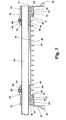
- a first mounting clamp 24 is inserted into the mount section 50A on the fender inner edge 42, and a second mounting clamp 24 is similarly joined with the mount section 50B on the fender outer edge 44.
- the mounting clamps 24 are positioned directly across from each other such that their bores 74 are axially aligned.
- the mounting clamp fingers 78 are aligned with the fender channels 62, the mounting clamp sloped ridges 80 are aligned with the fender sloped ridges 60, and the mounting clamp groove 76 is aligned with the fender panel 38.
- the former is slid into the latter such that the fender channels 62 receive the mounting clamp fingers 78, the sloped faces 61, 81 of the fender and mounting clamp sloped ridges 60, 80 abut in complementary fashion, and the mounting clamp groove 76 receives the lateral side surface 64 of the fender panel 38.
- the fender panel upper surface 40 exerts an upward force on the tab 96 of the lever 94, and, consequently, the lever 94 pivots into the bore 74. Movement of the lever 94 helps secure the fender assembly 10 together, as will be discussed in more detail hereinafter.
- the fender 22 and mounting clamps 24 are mounted to the mounting arm 26.
- the mounting clamp 24 on the fender inner edge 42 is slid onto the mounting arm 26 first and is followed by the mounting clamp 24 on the fender outer edge 44 such that the axially aligned bores 74 receive the mounting arm 26.
- the setscrews 88 are inserted into the openings 86, threaded into the T-nuts 89 and tightened to secure the mounting arm 26 and to prevent axial movement thereof within the bores 74.
- the setscrews 88 exert a downward force on the mounting arm 26, which in turn exerts a downward force on the lever 94. Combining this downward force with the upward force exerted by the panel 38, in conjunction with the interaction between the fingers 78 and channels 62 and between the sloped ridges 80, 60, helps securely clamp the mounting clamp 24 onto the fender 22.
- the fender assembly 20 can easily be partially disassembled to adjust the position thereof.
- the setscrews 88 are loosened, and the mounting clamps 24 and fender 22 are moved laterally relative to the mounting arm 26 for removal therefrom. Because the mounting arm 26 no longer clamps down on the lever 94, the mounting clamps 24 can easily be pulled from the mount sections 50 and repositioned along the length thereof in order to properly orient the fender 22. For example, if the fender 22 needs to be raised relative to the wheels 14, then the mounting clamps 24 are shifted to a lower position within the mount sections 50.
- the fender 22 can be adjusted to various degrees in several directions.
- adjustment of the fender E is limited to rotating the fender E about the point where the mounting arm B is attached to the vehicle frame C.
- the mounting clamps 24 are simply pulled from the mount sections 50 and reinserted at a new desired location. Repositioning the mounting clamps 24 is a quick process that requires neither extensive labor nor physical alteration of the fender 22. After the mounting clamps 24 have been moved, then the fender 22 and attached mounting clamps 24 are mounted to the mounting arm 26 as described above.
- the invention addresses the deficiencies of the prior art by providing a fender assembly comprising a fender and mounting clamps adapted to be removably coupled thereto to facilitate mounting the fender to a vehicle without permanently altering (e.g. drilling or welding) the fender.
- the fender and the mounting clamps include reciprocal mating elements in the form of fingers/channels and sloped ridges that interlock to securely retain the fender between the mounting clamps and easily separate for removing the mounting clamps from the fender. Consequently, the fender can be quickly mounted to the vehicle and, if necessary, easily adjusted in several directions thereafter.
- the fender assembly does not require drilling, welding, or other laborious installation processes, and the fender can be accurately mounted to the vehicle in a desired position, even when working within a limited space on and near the vehicle frame. Further, because the fender assembly is adjustable, it can be utilized on several types of vehicles and can be transferred from one vehicle to another if desired.
- one of the mounting clamps can be permanently mounted to the mounting arm and the other mounting clamp can be releasably mounted to the mounting arm.
- both mounting clamps are identical, they need not be identical.
- only one of the mounting clamps and one edge of the fender can have the complementary serrations and the other mounting clamp and other edge of the fender can be without the complementary serrations.
Landscapes
- Engineering & Computer Science (AREA)
- Chemical & Material Sciences (AREA)
- Combustion & Propulsion (AREA)
- Transportation (AREA)
- Mechanical Engineering (AREA)
- Body Structure For Vehicles (AREA)
Abstract
Description
Claims (30)
- A fender assembly comprising a vehicle fender, a mounting arm adapted to be attached to a vehicle frame at one end and adapted to support the fender at the other end; and a pair of mounting clamps that are mounted on the mounting arm and to the fender, characterized in that the mounting clamps are adapted to mount to the fender for selective adjustment of the fender with respect to the mounting arm and with respect to the frame of a vehicle when the one end of the mounting arm is attached to a vehicle frame.
- A fender assembly according to claim 1 wherein the mounting clamps are adapted to clamp the fender between them when the mounting clamps are mounted to the mounting arm.
- A fender assembly according to claim 1 wherein at least one of the mounting clamps is adapted to releasably mount to the mounting arm.
- A fender assembly according to any of claims 1 - 3 wherein the fender has side edges and the mounting clamps have grooves that receive a portion of the side edges of the fender.
- A fender assembly according to claim 4 wherein the fender and the mounting clamps include complementary mating elements that lock the clamps and fender in an adjusted relationship.
- A fender assembly according to claim 5 wherein the complementary mating elements are in the form of serrations on the fender side edges and on the groove in the mounting clamps.
- A fender assembly according to claim 6 wherein the serrations comprise channels and fingers.
- A fender assembly according to claims 6 or 7 wherein the complementary mating elements further comprise complementary sloped ridges between the channels and fingers on the fender side edges and the groove in the mounting clamps.
- A fender assembly according to any of claims 4-8 wherein the fender is integrally molded of a synthetic plastic resin.
- A fender assembly according to claim 9 wherein the synthetic plastic resin is a high density polypropylene.
- A fender assembly according to any of claims 1-10 wherein the mounting clamps are integrally molded of a synthetic plastic resin.
- A fender assembly according to claim 11 wherein the mounting clamps are integrally molded of a fiberglass-filled nylon.
- A fender assembly according to any of claims 1-12 and further comprising a bore in mounting clamps for receiving the mounting arm.
- A fender assembly according to claim 13 and further comprising a threaded aperture in the mounting clamps transverse to and intersecting the bore, and a set screw in threaded apertures for releasably retaining the relative positions of the mounting clamps on the mounting arms.
- A fender assembly according to claim 14 wherein the threaded bore is formed in a metal T nut mounted in a through hole in the mounting clamps, wherein the T nut has a lateral flange that is received in the bore.
- A fender assembly according to any of claims 4-8 wherein the portions of the fender side edges that are received in the groove form undercut pockets that receive a portion of the mounting clamps.
- A fender assembly according to any of claims 1 - 3 wherein the clamps are adapted to adjustably mount to the fender without physical alteration of the fender.
- A fender assembly according to any of claims 1 -3 wherein the mounting clamps are adapted to releasably clamp the fender between them.
- A fender assembly according to claim 18 wherein the fender and the or each mounting clamp includes complementary mating elements that lock the at least one clamp and fender in an adjusted relationship.
- A fender assembly according to claim 19 wherein the complementary mating elements are in the form of serrations on the fender side edges and a groove in the at least one mounting clamp.
- A mounting clamp for use in adjustably mounting a fender to a vehicle and having an attachment part for releasably attaching the clamp to a mounting arm that is adapted to be attached to a vehicle, characterized in that the mounting clamp has a groove that is adapted to receive a portion of side edges of the fender to clamp the fender to a pair of the clamps.
- A mounting clamp according to claim 21 wherein the groove has a plurality of serrations for gripping the side edges of a fender.
- A mounting clamp according to claim 22 wherein the serrations comprise channels and fingers.
- A mounting clamp according to claim 23 and further comprising complementary sloped ridges between the channels and fingers on the groove.
- A mounting clamp according to claim 24 wherein the mounting clamps are integrally molded of a synthetic plastic resin.
- A vehicle fender adapted to adjustably mount to a vehicle without alteration of the fender characterized in that side edges of the fender have serrations on inner and outer edges thereof that are adapted to mate with clamps that have complementary serrations and are supported by a support arm that is adapted to be mounted to a vehicle.
- A vehicle fender according to claim 26 wherein the serrations comprise channels and fingers.
- A vehicle fender according to claim 27 and further comprising complementary sloped ridges between the channels and fingers.
- A vehicle according to claim 28 wherein the fender is integrally molded of a synthetic plastic resin.
- A vehicle fender according to claim 26 wherein portions of the fender side edges form undercut pockets that are adapted to receive a portion of mounting clamps.
Applications Claiming Priority (2)
| Application Number | Priority Date | Filing Date | Title |
|---|---|---|---|
| US52106504P | 2004-02-13 | 2004-02-13 | |
| US521065P | 2004-02-13 |
Publications (3)
| Publication Number | Publication Date |
|---|---|
| EP1564115A2 true EP1564115A2 (en) | 2005-08-17 |
| EP1564115A3 EP1564115A3 (en) | 2006-07-05 |
| EP1564115B1 EP1564115B1 (en) | 2011-11-02 |
Family
ID=34699852
Family Applications (1)
| Application Number | Title | Priority Date | Filing Date |
|---|---|---|---|
| EP05002962A Ceased EP1564115B1 (en) | 2004-02-13 | 2005-02-11 | Fender assembly and mounting clamp therefor |
Country Status (5)
| Country | Link |
|---|---|
| US (1) | US7384071B2 (en) |
| EP (1) | EP1564115B1 (en) |
| AT (1) | ATE531606T1 (en) |
| AU (1) | AU2005200596B2 (en) |
| CA (1) | CA2496482C (en) |
Cited By (11)
| Publication number | Priority date | Publication date | Assignee | Title |
|---|---|---|---|---|
| EP1982901A3 (en) * | 2007-04-16 | 2009-07-15 | Fleet Engineers, Inc. | Adjustable fender mount |
| CN102372033A (en) * | 2010-07-07 | 2012-03-14 | 曼卡车和巴士股份公司 | Fenders for commercial vehicles |
| ITMI20111134A1 (en) * | 2011-06-22 | 2012-12-23 | Domar Srl | FENDER |
| USD697844S1 (en) * | 2013-03-01 | 2014-01-21 | Paccar Inc | Quarter fender |
| USD697845S1 (en) * | 2013-03-01 | 2014-01-21 | Paccar Inc | Quarter fender |
| USD697846S1 (en) * | 2013-03-01 | 2014-01-21 | Paccar Inc | Quarter fender |
| USD702606S1 (en) * | 2013-03-01 | 2014-04-15 | Paccar Inc | Quarter fender |
| USD786753S1 (en) | 2015-09-21 | 2017-05-16 | Paccar Inc | Quarter fender |
| USD786754S1 (en) | 2015-09-21 | 2017-05-16 | Paccar Inc | Quarter fender |
| WO2017204715A1 (en) * | 2016-05-26 | 2017-11-30 | Scania Cv Ab | An attachment assembly for mounting a mudguard and a mudguard assembly |
| US11186322B2 (en) | 2018-05-24 | 2021-11-30 | Paccar Inc | Curved quarter fender rock guard |
Families Citing this family (13)
| Publication number | Priority date | Publication date | Assignee | Title |
|---|---|---|---|---|
| US7370888B2 (en) * | 2004-05-06 | 2008-05-13 | Bridgestone Firestone North American Tire, Llc | Apparatus and method for enhancing tire traction |
| PT103383B (en) * | 2005-11-14 | 2007-09-11 | Polisport Pedro & Paulo Araujo | MOTORCYCLES LOCKING SYSTEM FOR MOTORCYCLES |
| US7469929B2 (en) * | 2006-03-31 | 2008-12-30 | Produits Metchro Inc. | Bidirectionally and angularly adjustable fender attaching device |
| GB201121888D0 (en) * | 2011-12-20 | 2012-02-01 | Agco Sa | Fender mounting assembly for utility vehicles |
| US9643657B2 (en) * | 2013-10-09 | 2017-05-09 | Truckmovers.Com, Inc. | Mud flap system |
| CN104118479B (en) * | 2013-12-19 | 2017-10-24 | 东风柳州汽车有限公司 | Anti- mud guard tumbler |
| US10513301B2 (en) | 2016-05-05 | 2019-12-24 | Lyft, Inc. | Fender and fender assembly for a cycling apparatus |
| CN109178112B (en) * | 2018-11-01 | 2024-10-11 | 徐州徐工环境技术有限公司 | Fixing assembly of vehicle mud shield and vehicle |
| US11345411B2 (en) | 2020-04-24 | 2022-05-31 | Mfc Technology Corp. | Toolless mud flap mounting system and method |
| CN111516760B (en) * | 2020-04-27 | 2022-07-22 | 东风柳州汽车有限公司 | Fender device |
| USD928676S1 (en) * | 2020-04-29 | 2021-08-24 | Matthew Brett Hoover | Fender |
| CN112606914B (en) * | 2020-12-23 | 2021-11-26 | 舒城县河棚科技创新协会 | Automobile mudguard device convenient to wash and change |
| CN113147909B (en) * | 2021-05-24 | 2022-04-19 | 安徽安凯汽车股份有限公司 | Passenger train punching press wheel protecting surface |
Citations (3)
| Publication number | Priority date | Publication date | Assignee | Title |
|---|---|---|---|---|
| US1434477A (en) | 1922-05-13 | 1922-11-07 | Thomas J Bury | Fender brace |
| DE8609090U1 (en) | 1986-04-04 | 1987-07-30 | BÄWA Bätzold & Wagner GmbH & Co KG, 5608 Radevormwald | Holding device for fenders on trucks |
| EP1172283A1 (en) | 2000-07-13 | 2002-01-16 | Polyrim | Adjustable fixation for plastic parts such as vehicle mudguards and wings |
Family Cites Families (27)
| Publication number | Priority date | Publication date | Assignee | Title |
|---|---|---|---|---|
| US817203A (en) | 1904-10-17 | 1906-04-10 | Wilson & Hayes Mfg Co | Mud-guard fastening. |
| US1094134A (en) | 1913-11-13 | 1914-04-21 | Detroit Auto Specialty Co | Mud-guard for vehicles. |
| US1158947A (en) * | 1914-06-19 | 1915-11-02 | Allan L Mcgregor | Adjusting means for automobile-buffers. |
| US1511813A (en) * | 1922-02-25 | 1924-10-14 | J W Stephenson | Friction chock for cars |
| US1550247A (en) | 1922-11-17 | 1925-08-18 | Metal Products Co | Fender brace |
| US1489062A (en) | 1923-03-17 | 1924-04-01 | James F Burnam | Fender brace |
| US1551813A (en) | 1923-07-05 | 1925-09-01 | William G Dunn | Automobile fender brace |
| US1519860A (en) | 1924-04-22 | 1924-12-16 | Arthur J Mcclelland | Auto fender brace lug |
| US1593063A (en) | 1924-12-01 | 1926-07-20 | William G Dunn | Fender brace |
| US1537852A (en) * | 1924-12-23 | 1925-05-12 | Arthur J Mandry | Fender brace |
| US1667209A (en) | 1925-08-17 | 1928-04-24 | Petroleum Machinery Dev Corp | Truss rod |
| US2068732A (en) * | 1934-02-21 | 1937-01-26 | Chrysler Corp | Automobile fender |
| US4377294A (en) | 1981-03-17 | 1983-03-22 | Lancaster Colony Corporation | Vehicle fender and support bar |
| US4591178A (en) | 1984-07-12 | 1986-05-27 | Genes' Enterprise Corp. | Quick attach fender and method for using same |
| US4712805A (en) * | 1986-03-13 | 1987-12-15 | Mcmillen Russell G | Flexible mounting for splash/spray control guards and the like |
| US5165712A (en) * | 1991-03-27 | 1992-11-24 | Fuller Wyatt S | Floating fender mount and method |
| FR2690125B1 (en) | 1992-04-16 | 1998-05-22 | Poutrait Morin | REAR FENDERS IN PARTICULAR FOR ROAD BIKES. |
| DE9409662U1 (en) | 1994-06-15 | 1994-08-11 | Dunlop GmbH, 63450 Hanau | Device for mounting fenders |
| US5950975A (en) | 1995-02-09 | 1999-09-14 | Zieske; Robert L. | Adjustable fender bracket |
| US6029999A (en) * | 1997-04-19 | 2000-02-29 | O'day; John M. | Adjustable splash guard assembly |
| US6186527B1 (en) * | 1998-03-06 | 2001-02-13 | Garry Monhollen | Mud flap assembly |
| US6354625B1 (en) | 1999-11-09 | 2002-03-12 | U-Haul International, Inc. | Fender having element conforming to mounting bracket |
| US6199883B1 (en) * | 2000-06-29 | 2001-03-13 | Jack C. Gable | Articulated rear fender for bicycles |
| US6648373B2 (en) * | 2000-08-29 | 2003-11-18 | Fleet Engineers, Incorporated | Fender assembly and mounting bracket assembly therefor |
| US6634664B1 (en) * | 2000-10-31 | 2003-10-21 | Shimano Inc. | Multi-purpose mounting member for bicycle |
| US7810829B2 (en) * | 2002-07-03 | 2010-10-12 | Fleet Engineers, Incorporated | Fender assembly and adjustable mounting bracket therefor |
| US6893048B2 (en) * | 2003-07-01 | 2005-05-17 | Deere & Company | Flexible fender mount |
-
2005
- 2005-02-09 US US10/906,215 patent/US7384071B2/en not_active Expired - Lifetime
- 2005-02-10 AU AU2005200596A patent/AU2005200596B2/en not_active Ceased
- 2005-02-10 CA CA002496482A patent/CA2496482C/en not_active Expired - Lifetime
- 2005-02-11 AT AT05002962T patent/ATE531606T1/en active
- 2005-02-11 EP EP05002962A patent/EP1564115B1/en not_active Ceased
Patent Citations (3)
| Publication number | Priority date | Publication date | Assignee | Title |
|---|---|---|---|---|
| US1434477A (en) | 1922-05-13 | 1922-11-07 | Thomas J Bury | Fender brace |
| DE8609090U1 (en) | 1986-04-04 | 1987-07-30 | BÄWA Bätzold & Wagner GmbH & Co KG, 5608 Radevormwald | Holding device for fenders on trucks |
| EP1172283A1 (en) | 2000-07-13 | 2002-01-16 | Polyrim | Adjustable fixation for plastic parts such as vehicle mudguards and wings |
Cited By (19)
| Publication number | Priority date | Publication date | Assignee | Title |
|---|---|---|---|---|
| US7874592B2 (en) | 2005-02-09 | 2011-01-25 | Fleet Engineers, Incorporated | Adjustable fender mount |
| EP1982901A3 (en) * | 2007-04-16 | 2009-07-15 | Fleet Engineers, Inc. | Adjustable fender mount |
| US8066305B2 (en) | 2007-04-16 | 2011-11-29 | Fleet Engineers, Incorporated | Adjustable fender |
| AU2008201214B2 (en) * | 2007-04-16 | 2012-05-17 | Fleet Engineers, Inc. | Adjustable fender mount |
| CN102372033A (en) * | 2010-07-07 | 2012-03-14 | 曼卡车和巴士股份公司 | Fenders for commercial vehicles |
| EP2404814A3 (en) * | 2010-07-07 | 2012-03-21 | MAN Truck & Bus AG | Wing for a commercial vehicle |
| CN105691467A (en) * | 2010-07-07 | 2016-06-22 | 曼卡车和巴士股份公司 | Mudguard for a commercial vehicle |
| ITMI20111134A1 (en) * | 2011-06-22 | 2012-12-23 | Domar Srl | FENDER |
| USD697845S1 (en) * | 2013-03-01 | 2014-01-21 | Paccar Inc | Quarter fender |
| USD697846S1 (en) * | 2013-03-01 | 2014-01-21 | Paccar Inc | Quarter fender |
| USD702606S1 (en) * | 2013-03-01 | 2014-04-15 | Paccar Inc | Quarter fender |
| USD697844S1 (en) * | 2013-03-01 | 2014-01-21 | Paccar Inc | Quarter fender |
| USD786753S1 (en) | 2015-09-21 | 2017-05-16 | Paccar Inc | Quarter fender |
| USD786754S1 (en) | 2015-09-21 | 2017-05-16 | Paccar Inc | Quarter fender |
| WO2017204715A1 (en) * | 2016-05-26 | 2017-11-30 | Scania Cv Ab | An attachment assembly for mounting a mudguard and a mudguard assembly |
| KR20180134414A (en) * | 2016-05-26 | 2018-12-18 | 스카니아 씨브이 악티에볼라그 | Mounting assembly and mud guard assembly for mounting the mud guard |
| CN109153414A (en) * | 2016-05-26 | 2019-01-04 | 斯堪尼亚商用车有限公司 | For installing the attachment assembly and gear mud part component of gear mud part |
| CN109153414B (en) * | 2016-05-26 | 2021-03-19 | 斯堪尼亚商用车有限公司 | Attachment kits and fender assemblies for installing fenders |
| US11186322B2 (en) | 2018-05-24 | 2021-11-30 | Paccar Inc | Curved quarter fender rock guard |
Also Published As
| Publication number | Publication date |
|---|---|
| CA2496482C (en) | 2009-11-10 |
| US7384071B2 (en) | 2008-06-10 |
| CA2496482A1 (en) | 2005-08-13 |
| EP1564115B1 (en) | 2011-11-02 |
| AU2005200596B2 (en) | 2009-04-02 |
| US20050179245A1 (en) | 2005-08-18 |
| AU2005200596A1 (en) | 2005-09-01 |
| EP1564115A3 (en) | 2006-07-05 |
| ATE531606T1 (en) | 2011-11-15 |
Similar Documents
| Publication | Publication Date | Title |
|---|---|---|
| CA2496482C (en) | Fender assembly and mounting clamping member therefor | |
| EP1982901B1 (en) | Adjustable fender mount | |
| EP0451238B1 (en) | Automobile mountable bicycle carrier | |
| US4507105A (en) | Bicycle chainguard | |
| US5967553A (en) | Bracket for mud flaps and snowplow diverters | |
| EP1961650B1 (en) | Bicycle wheel securing structure | |
| US5489107A (en) | Suitcase wheel assembly and retainer | |
| US7073804B2 (en) | Fender assembly and adjustable mounting bracket therefor | |
| EP3464032B1 (en) | An attachment assembly for mounting a mudguard and a mudguard assembly | |
| TW202500435A (en) | Telescoping bicycle support assembly | |
| US20050056763A1 (en) | Spare tire bracket | |
| US5870236A (en) | Towing mirror extension | |
| US11772711B2 (en) | Fender support arm with bolt-retaining strip | |
| US6471228B2 (en) | Offset mounting bracket | |
| US20040239066A1 (en) | Damper-mounting structure | |
| WO2016037215A1 (en) | A roof rack support assembly | |
| JPS6225914Y2 (en) | ||
| US20240107929A1 (en) | Hitch for a vehicle | |
| JPH11129944A (en) | Spare tire holder | |
| JP2003276561A (en) | Seat belt retractor mounting structure | |
| JP2726000B2 (en) | Automotive flagpole fixtures | |
| KR200141559Y1 (en) | Structure for fixing tapping nut | |
| US20030005675A1 (en) | Wheeled support for vegetation trimmer | |
| JP2000016351A (en) | Cab hinge bracket fastening structure | |
| CA2000414A1 (en) | Seat post assembly |
Legal Events
| Date | Code | Title | Description |
|---|---|---|---|
| PUAI | Public reference made under article 153(3) epc to a published international application that has entered the european phase |
Free format text: ORIGINAL CODE: 0009012 |
|
| AK | Designated contracting states |
Kind code of ref document: A2 Designated state(s): AT BE BG CH CY CZ DE DK EE ES FI FR GB GR HU IE IS IT LI LT LU MC NL PL PT RO SE SI SK TR |
|
| AX | Request for extension of the european patent |
Extension state: AL BA HR LV MK YU |
|
| PUAL | Search report despatched |
Free format text: ORIGINAL CODE: 0009013 |
|
| AK | Designated contracting states |
Kind code of ref document: A3 Designated state(s): AT BE BG CH CY CZ DE DK EE ES FI FR GB GR HU IE IS IT LI LT LU MC NL PL PT RO SE SI SK TR |
|
| AX | Request for extension of the european patent |
Extension state: AL BA HR LV MK YU |
|
| 17P | Request for examination filed |
Effective date: 20060803 |
|
| AKX | Designation fees paid |
Designated state(s): AT BE BG CH CY CZ DE DK EE ES FI FR GB GR HU IE IS IT LI LT LU MC NL PL PT RO SE SI SK TR |
|
| 17Q | First examination report despatched |
Effective date: 20080714 |
|
| GRAP | Despatch of communication of intention to grant a patent |
Free format text: ORIGINAL CODE: EPIDOSNIGR1 |
|
| GRAS | Grant fee paid |
Free format text: ORIGINAL CODE: EPIDOSNIGR3 |
|
| GRAA | (expected) grant |
Free format text: ORIGINAL CODE: 0009210 |
|
| AK | Designated contracting states |
Kind code of ref document: B1 Designated state(s): AT BE BG CH CY CZ DE DK EE ES FI FR GB GR HU IE IS IT LI LT LU MC NL PL PT RO SE SI SK TR |
|
| REG | Reference to a national code |
Ref country code: GB Ref legal event code: FG4D |
|
| REG | Reference to a national code |
Ref country code: CH Ref legal event code: EP |
|
| REG | Reference to a national code |
Ref country code: IE Ref legal event code: FG4D |
|
| REG | Reference to a national code |
Ref country code: DE Ref legal event code: R096 Ref document number: 602005030898 Country of ref document: DE Effective date: 20120112 |
|
| REG | Reference to a national code |
Ref country code: NL Ref legal event code: T3 |
|
| LTIE | Lt: invalidation of european patent or patent extension |
Effective date: 20111102 |
|
| PG25 | Lapsed in a contracting state [announced via postgrant information from national office to epo] |
Ref country code: LT Free format text: LAPSE BECAUSE OF FAILURE TO SUBMIT A TRANSLATION OF THE DESCRIPTION OR TO PAY THE FEE WITHIN THE PRESCRIBED TIME-LIMIT Effective date: 20111102 Ref country code: IS Free format text: LAPSE BECAUSE OF FAILURE TO SUBMIT A TRANSLATION OF THE DESCRIPTION OR TO PAY THE FEE WITHIN THE PRESCRIBED TIME-LIMIT Effective date: 20120302 |
|
| PG25 | Lapsed in a contracting state [announced via postgrant information from national office to epo] |
Ref country code: SI Free format text: LAPSE BECAUSE OF FAILURE TO SUBMIT A TRANSLATION OF THE DESCRIPTION OR TO PAY THE FEE WITHIN THE PRESCRIBED TIME-LIMIT Effective date: 20111102 Ref country code: BE Free format text: LAPSE BECAUSE OF FAILURE TO SUBMIT A TRANSLATION OF THE DESCRIPTION OR TO PAY THE FEE WITHIN THE PRESCRIBED TIME-LIMIT Effective date: 20111102 Ref country code: PL Free format text: LAPSE BECAUSE OF FAILURE TO SUBMIT A TRANSLATION OF THE DESCRIPTION OR TO PAY THE FEE WITHIN THE PRESCRIBED TIME-LIMIT Effective date: 20111102 Ref country code: GR Free format text: LAPSE BECAUSE OF FAILURE TO SUBMIT A TRANSLATION OF THE DESCRIPTION OR TO PAY THE FEE WITHIN THE PRESCRIBED TIME-LIMIT Effective date: 20120203 Ref country code: SE Free format text: LAPSE BECAUSE OF FAILURE TO SUBMIT A TRANSLATION OF THE DESCRIPTION OR TO PAY THE FEE WITHIN THE PRESCRIBED TIME-LIMIT Effective date: 20111102 Ref country code: PT Free format text: LAPSE BECAUSE OF FAILURE TO SUBMIT A TRANSLATION OF THE DESCRIPTION OR TO PAY THE FEE WITHIN THE PRESCRIBED TIME-LIMIT Effective date: 20120302 |
|
| PG25 | Lapsed in a contracting state [announced via postgrant information from national office to epo] |
Ref country code: CY Free format text: LAPSE BECAUSE OF FAILURE TO SUBMIT A TRANSLATION OF THE DESCRIPTION OR TO PAY THE FEE WITHIN THE PRESCRIBED TIME-LIMIT Effective date: 20111102 |
|
| PG25 | Lapsed in a contracting state [announced via postgrant information from national office to epo] |
Ref country code: BG Free format text: LAPSE BECAUSE OF FAILURE TO SUBMIT A TRANSLATION OF THE DESCRIPTION OR TO PAY THE FEE WITHIN THE PRESCRIBED TIME-LIMIT Effective date: 20120202 Ref country code: EE Free format text: LAPSE BECAUSE OF FAILURE TO SUBMIT A TRANSLATION OF THE DESCRIPTION OR TO PAY THE FEE WITHIN THE PRESCRIBED TIME-LIMIT Effective date: 20111102 Ref country code: SK Free format text: LAPSE BECAUSE OF FAILURE TO SUBMIT A TRANSLATION OF THE DESCRIPTION OR TO PAY THE FEE WITHIN THE PRESCRIBED TIME-LIMIT Effective date: 20111102 Ref country code: CZ Free format text: LAPSE BECAUSE OF FAILURE TO SUBMIT A TRANSLATION OF THE DESCRIPTION OR TO PAY THE FEE WITHIN THE PRESCRIBED TIME-LIMIT Effective date: 20111102 Ref country code: DK Free format text: LAPSE BECAUSE OF FAILURE TO SUBMIT A TRANSLATION OF THE DESCRIPTION OR TO PAY THE FEE WITHIN THE PRESCRIBED TIME-LIMIT Effective date: 20111102 |
|
| PG25 | Lapsed in a contracting state [announced via postgrant information from national office to epo] |
Ref country code: RO Free format text: LAPSE BECAUSE OF FAILURE TO SUBMIT A TRANSLATION OF THE DESCRIPTION OR TO PAY THE FEE WITHIN THE PRESCRIBED TIME-LIMIT Effective date: 20111102 |
|
| PLBE | No opposition filed within time limit |
Free format text: ORIGINAL CODE: 0009261 |
|
| STAA | Information on the status of an ep patent application or granted ep patent |
Free format text: STATUS: NO OPPOSITION FILED WITHIN TIME LIMIT |
|
| REG | Reference to a national code |
Ref country code: AT Ref legal event code: MK05 Ref document number: 531606 Country of ref document: AT Kind code of ref document: T Effective date: 20111102 |
|
| PG25 | Lapsed in a contracting state [announced via postgrant information from national office to epo] |
Ref country code: MC Free format text: LAPSE BECAUSE OF NON-PAYMENT OF DUE FEES Effective date: 20120229 |
|
| REG | Reference to a national code |
Ref country code: CH Ref legal event code: PL |
|
| 26N | No opposition filed |
Effective date: 20120803 |
|
| PG25 | Lapsed in a contracting state [announced via postgrant information from national office to epo] |
Ref country code: CH Free format text: LAPSE BECAUSE OF NON-PAYMENT OF DUE FEES Effective date: 20120229 Ref country code: LI Free format text: LAPSE BECAUSE OF NON-PAYMENT OF DUE FEES Effective date: 20120229 |
|
| REG | Reference to a national code |
Ref country code: DE Ref legal event code: R097 Ref document number: 602005030898 Country of ref document: DE Effective date: 20120803 |
|
| PG25 | Lapsed in a contracting state [announced via postgrant information from national office to epo] |
Ref country code: AT Free format text: LAPSE BECAUSE OF FAILURE TO SUBMIT A TRANSLATION OF THE DESCRIPTION OR TO PAY THE FEE WITHIN THE PRESCRIBED TIME-LIMIT Effective date: 20111102 |
|
| PG25 | Lapsed in a contracting state [announced via postgrant information from national office to epo] |
Ref country code: ES Free format text: LAPSE BECAUSE OF FAILURE TO SUBMIT A TRANSLATION OF THE DESCRIPTION OR TO PAY THE FEE WITHIN THE PRESCRIBED TIME-LIMIT Effective date: 20120213 |
|
| PG25 | Lapsed in a contracting state [announced via postgrant information from national office to epo] |
Ref country code: FI Free format text: LAPSE BECAUSE OF FAILURE TO SUBMIT A TRANSLATION OF THE DESCRIPTION OR TO PAY THE FEE WITHIN THE PRESCRIBED TIME-LIMIT Effective date: 20111102 |
|
| PG25 | Lapsed in a contracting state [announced via postgrant information from national office to epo] |
Ref country code: TR Free format text: LAPSE BECAUSE OF FAILURE TO SUBMIT A TRANSLATION OF THE DESCRIPTION OR TO PAY THE FEE WITHIN THE PRESCRIBED TIME-LIMIT Effective date: 20111102 |
|
| PG25 | Lapsed in a contracting state [announced via postgrant information from national office to epo] |
Ref country code: LU Free format text: LAPSE BECAUSE OF NON-PAYMENT OF DUE FEES Effective date: 20120211 |
|
| PG25 | Lapsed in a contracting state [announced via postgrant information from national office to epo] |
Ref country code: HU Free format text: LAPSE BECAUSE OF FAILURE TO SUBMIT A TRANSLATION OF THE DESCRIPTION OR TO PAY THE FEE WITHIN THE PRESCRIBED TIME-LIMIT Effective date: 20050211 |
|
| REG | Reference to a national code |
Ref country code: DE Ref legal event code: R082 Ref document number: 602005030898 Country of ref document: DE Representative=s name: SCHAUMBURG & PARTNER PATENTANWAELTE GBR, DE Ref country code: DE Ref legal event code: R082 Ref document number: 602005030898 Country of ref document: DE Representative=s name: SCHAUMBURG & PARTNER PATENTANWAELTE MBB, DE Ref country code: DE Ref legal event code: R082 Ref document number: 602005030898 Country of ref document: DE Representative=s name: SCHAUMBURG UND PARTNER PATENTANWAELTE MBB, DE |
|
| REG | Reference to a national code |
Ref country code: FR Ref legal event code: PLFP Year of fee payment: 12 |
|
| REG | Reference to a national code |
Ref country code: FR Ref legal event code: PLFP Year of fee payment: 13 |
|
| REG | Reference to a national code |
Ref country code: FR Ref legal event code: PLFP Year of fee payment: 14 |
|
| PGFP | Annual fee paid to national office [announced via postgrant information from national office to epo] |
Ref country code: GB Payment date: 20200225 Year of fee payment: 16 Ref country code: IT Payment date: 20200221 Year of fee payment: 16 Ref country code: NL Payment date: 20200220 Year of fee payment: 16 Ref country code: IE Payment date: 20200219 Year of fee payment: 16 Ref country code: DE Payment date: 20200318 Year of fee payment: 16 |
|
| PGFP | Annual fee paid to national office [announced via postgrant information from national office to epo] |
Ref country code: FR Payment date: 20200219 Year of fee payment: 16 |
|
| REG | Reference to a national code |
Ref country code: DE Ref legal event code: R119 Ref document number: 602005030898 Country of ref document: DE |
|
| GBPC | Gb: european patent ceased through non-payment of renewal fee |
Effective date: 20210211 |
|
| REG | Reference to a national code |
Ref country code: NL Ref legal event code: MM Effective date: 20210301 |
|
| PG25 | Lapsed in a contracting state [announced via postgrant information from national office to epo] |
Ref country code: NL Free format text: LAPSE BECAUSE OF NON-PAYMENT OF DUE FEES Effective date: 20210301 |
|
| PG25 | Lapsed in a contracting state [announced via postgrant information from national office to epo] |
Ref country code: IE Free format text: LAPSE BECAUSE OF NON-PAYMENT OF DUE FEES Effective date: 20210211 Ref country code: FR Free format text: LAPSE BECAUSE OF NON-PAYMENT OF DUE FEES Effective date: 20210228 Ref country code: GB Free format text: LAPSE BECAUSE OF NON-PAYMENT OF DUE FEES Effective date: 20210211 Ref country code: DE Free format text: LAPSE BECAUSE OF NON-PAYMENT OF DUE FEES Effective date: 20210901 |
|
| PG25 | Lapsed in a contracting state [announced via postgrant information from national office to epo] |
Ref country code: IT Free format text: LAPSE BECAUSE OF NON-PAYMENT OF DUE FEES Effective date: 20210211 |