EP1564111A2 - Mounting arrangement for a vehicle subframe - Google Patents
Mounting arrangement for a vehicle subframe Download PDFInfo
- Publication number
- EP1564111A2 EP1564111A2 EP05001782A EP05001782A EP1564111A2 EP 1564111 A2 EP1564111 A2 EP 1564111A2 EP 05001782 A EP05001782 A EP 05001782A EP 05001782 A EP05001782 A EP 05001782A EP 1564111 A2 EP1564111 A2 EP 1564111A2
- Authority
- EP
- European Patent Office
- Prior art keywords
- bearing
- vehicle
- arrangement according
- flange
- core
- Prior art date
- Legal status (The legal status is an assumption and is not a legal conclusion. Google has not performed a legal analysis and makes no representation as to the accuracy of the status listed.)
- Granted
Links
Images

Classifications
-
- B—PERFORMING OPERATIONS; TRANSPORTING
- B62—LAND VEHICLES FOR TRAVELLING OTHERWISE THAN ON RAILS
- B62D—MOTOR VEHICLES; TRAILERS
- B62D21/00—Understructures, i.e. chassis frame on which a vehicle body may be mounted
- B62D21/11—Understructures, i.e. chassis frame on which a vehicle body may be mounted with resilient means for suspension, e.g. of wheels or engine; sub-frames for mounting engine or suspensions
-
- B—PERFORMING OPERATIONS; TRANSPORTING
- B60—VEHICLES IN GENERAL
- B60G—VEHICLE SUSPENSION ARRANGEMENTS
- B60G2204/00—Indexing codes related to suspensions per se or to auxiliary parts
- B60G2204/10—Mounting of suspension elements
- B60G2204/15—Mounting of subframes
Definitions
- the invention relates to a bearing assembly of a subframe with connection to the Vehicle body, comprising a vehicle longitudinal direction X, vehicle transverse direction Y andggyhochraum Z, wherein a hole in the subframe, the bearing, the one Includes bearing axis and a free bearing end face, the bearing at least consists of an elastomeric body.
- the orientation of the bearing axis is vertical (Vehicle vertical direction Z).
- the subframe In the subframe are vertical holes attached, which take up the camp. The screwing of the subframe takes place by means of through bolts through the hole in the core of the subframe bearing.
- vertical Verschraubungsraum guaranteed.
- Recesses called kidneys, reached in the elastomeric body of the bearing.
- the bearings with which the subframe is connected to the structure should be in Vehicle transverse direction Y hard compared to the vehicle longitudinal direction X and Be vehicle vertical Z.
- the high rigidity in the transverse direction from about 2000 to 4000 N / mm follows from the desire for direct response of the vehicle, especially during steering movement (low self-steering movements of the axle).
- the im Comparison small rigidity in the longitudinal and vertical direction of 500 to 1000 N / mm corresponds the desire for comfortable behavior of the vehicle when driving over Road bumps.
- the Y-direction of storage differs in their requirement substantially from the X and Z direction.
- the object of the invention is one in this regard provide optimal solution, even from a more cost-effective point of view.
- vehicle 1 shows a vehicle or its vehicle body 1, its wheel side 2 and subframe 3.
- the three spatial directions are: vehicle longitudinal direction X, vehicle transverse direction Y and vehicle vertical direction Z.
- the subframe has four receiving bores, all of which extend in vehicle vertical direction Z. These holes take up the respective bearing (area A), reference being made in this regard to the introduction to the description.
- Fig. 2 shows the same vehicle with the subframe 3, in which case, however, the corresponding receiving holes 4 for the respective retractable bearing 5 in the vehicle transverse direction Y extend (lying subframe in area B).
- the core 6 and the outer sleeve 8 are usually made of metal, in particular steel or aluminum. Corresponding plastics (eg based on polyphenyl ether, Vestoran® from Hüls) are also used.
- the elastomer body 9 is usually a vulcanized rubber mixture based on natural or a synthetic rubber, for example in the form of silicone rubber (DE 44 22 048 A1). The adhesion of the elastomeric body with the core and the outer sleeve takes place via the path of vulcanization.
- the connection of the bearing 5 on the vehicle body is done via the free or accessible outer core end face 10, here the bearing end face (Fig. 2, Area C) takes over.
- This core end face is formed from a running in vehicle vertical direction Z flange 11 , which takes over the connection of the bearing to the vehicle body.
- the core 6 is arranged here substantially in the region of the flange center 12 .
- the flange 11 is in a running in the vehicle transverse direction Y projection 13 , which is provided with a bore 14 for the screw connection.
- the outer sleeve 8 is also within its free end portion 15 in a running in the vehicle vertical direction Z flange 16 via. Between the flange 11 of the core 6 and the flange 16 of the outer sleeve 8 , an additional elastomer body 17 is arranged. With regard to the elastomer material, reference is made to what has already been stated in connection with the elastomer body 9 .
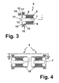
- the subframe 3 (FIG. 2) is supported by two opposing bearings according to FIG. 3 with a common bearing axis 7 in the vehicle transverse direction Y.
- the receiving bore for the two bearings comprises a tubular body 18 made of metal or plastic. With regard to the relevant material technology, the same applies as in the core and the outer sleeve.
- the bore 4 or the tubular body 18 can extend continuously in the vehicle transverse direction Y, connected to two openings. In each opening area a subframe is then introduced. For a total of four bearings then only two holes or tubular body are required.
- the bore 4 or the tubular body 18 can also extend in sections in the vehicle transverse direction Y. For a total of four bearings then four holes or tubular body are required here. This constellation is shown in FIG.
Landscapes
- Engineering & Computer Science (AREA)
- Chemical & Material Sciences (AREA)
- Combustion & Propulsion (AREA)
- Transportation (AREA)
- Mechanical Engineering (AREA)
- Body Structure For Vehicles (AREA)
Abstract
Description
Die Erfindung betrifft eine Lageranordnung eines Fahrschemels mit Anbindung an den Fahrzeugaufbau, umfassend eine Fahrzeuglängsrichtung X, Fahrzeugquerrichtung Y und Fahrzeughochrichtung Z, wobei eine Bohrung im Fahrschemel das Lager, das eine Lagerachse und eine freie Lagerstirnfläche umfasst, aufnimmt, wobei das Lager wenigstens aus einem Elastomerkörper besteht.The invention relates to a bearing assembly of a subframe with connection to the Vehicle body, comprising a vehicle longitudinal direction X, vehicle transverse direction Y and Fahrzeughochrichtung Z, wherein a hole in the subframe, the bearing, the one Includes bearing axis and a free bearing end face, the bearing at least consists of an elastomeric body.
Eine gattungsgemäße Lageranordnung ist beispielsweise in der Offenlegungsschrift DE 101 46 314 A1 beschrieben, wobei der diesbezügliche Stand der Technik nun näher vorgestellt wird.A generic bearing arrangement is for example in the published patent application DE 101 46 314 A1, wherein the relevant prior art now closer is presented.
Nach diesem Stand der Technik ist die Orientierung der Lagerachse vertikal (Fahrzeughochrichtung Z). In den Fahrschemel sind dabei senkrechte Bohrungen angebracht, die das Lager aufnehmen. Die Verschraubung des Fahrschemels erfolgt mittels Durchgangsschrauben durch die Bohrung im Kern des Fahrschemellagers. Damit ist die für die Montage gewünschte senkrechte Verschraubungsrichtung gewährleistet. Der Unterschied in der Steifigkeit in Quer- und Längsrichtung wird insbesondere durch Aussparungen, so genannte Nieren, im Elastomerkörper des Lagers erreicht.According to this prior art, the orientation of the bearing axis is vertical (Vehicle vertical direction Z). In the subframe are vertical holes attached, which take up the camp. The screwing of the subframe takes place by means of through bolts through the hole in the core of the subframe bearing. In order to is the desired for the installation vertical Verschraubungsrichtung guaranteed. Of the Difference in the stiffness in the transverse and longitudinal direction is in particular by Recesses, called kidneys, reached in the elastomeric body of the bearing.
Die Lager, mit denen der Fahrschemel mit dem Aufbau verbunden sind, sollen in Fahrzeugquerrichtung Y hart im Vergleich zur Fahrzeuglängsrichtung X und zur Fahrzeughochrichtung Z sein. Die hohe Steifigkeit in Querrichtung von ca. 2000 bis 4000 N/mm folgt aus dem Wunsch nach direktem Ansprechen des Fahrzeuges, insbesondere bei Lenkbewegung (geringe Eigenlenkbewegungen der Achse). Die im Vergleich kleine Steifigkeit in Längs- und Hochrichtung von 500 bis 1000 N/mm entspricht dem Wunsch nach komfortablem Verhalten des Fahrzeuges beim Überfahren von Fahrbahnunebenheiten. Zusammenfassend gilt: Die Y-Richtung der Lagerung unterscheidet sich in ihrer Anforderung wesentlich von der X- und Z-Richtung.The bearings with which the subframe is connected to the structure should be in Vehicle transverse direction Y hard compared to the vehicle longitudinal direction X and Be vehicle vertical Z. The high rigidity in the transverse direction from about 2000 to 4000 N / mm follows from the desire for direct response of the vehicle, especially during steering movement (low self-steering movements of the axle). The im Comparison small rigidity in the longitudinal and vertical direction of 500 to 1000 N / mm corresponds the desire for comfortable behavior of the vehicle when driving over Road bumps. In summary: The Y-direction of storage differs in their requirement substantially from the X and Z direction.
Im Hintergrund dieses Anforderungsprofils, das die bisher bekannten Fahrschemellager nur unzureichend erfüllen, besteht die Aufgabe der Erfindung darin, eine in dieser Hinsicht optimale Lösung bereitzustellen, auch unter einem kostengünstigeren Gesichtspunkt. In the background of this requirement profile, which is the previously known subframe Fulfill inadequate, the object of the invention is one in this regard provide optimal solution, even from a more cost-effective point of view.
Gelöst wird diese Aufgabe gemäß Kennzeichen des Patentspruches 1 dadurch, dass die
Lagerachse und die Aufnahmebohrung in Fahrzeugquerrichtung Y verlaufen, wobei das
Lager von der Radseite her in die Aufnahmebohrung einschiebbar ist, wobei die Anbindung
des Lagers an den Fahrzeugaufbau über die freie Lagerstirnfläche erfolgt.This object is achieved according to the
Zweckmäßige Ausgestaltungen der Erfindung sind in den Patentansprüchen 2 bis 11
genannt.Advantageous embodiments of the invention are in the
Die Erfindung wird nun unter Heranziehung des Standes der Technik (Fig. 1) anhand von Ausführungsbeispielen (Fig. 2 bis 4) unter Bezugnahme auf schematische Zeichnungen erläutert. Es zeigen:
- Fig. 1
- einen Fahrschemel mit Bohrungen in Fahrzeughochrichtung Z nach dem Stand der Technik;
- Fig. 2
- einen Fahrschemel mit Bohrungen in Fahrzeugquerrichtung Y;
- Fig. 3
- ein Lager in Buchsenform mit einer Lagerachse in Fahrzeugquerrichtung Y;
- Fig. 4
- zwei gegenüberliegende Lager mit einer gemeinsamen Lagerachse in Fahrzeugquerrichtung Y.
- Fig. 1
- a subframe with bores in the vehicle vertical direction Z according to the prior art;
- Fig. 2
- a subframe with holes in the vehicle transverse direction Y;
- Fig. 3
- a bearing in bushing form with a bearing axis in the vehicle transverse direction Y;
- Fig. 4
- two opposing bearings with a common bearing axis in the vehicle transverse direction Y.
Fig. 1 zeigt ein Fahrzeug bzw. dessen Fahrzeugaufbau 1, dessen Radseite 2 sowie
Fahrschemel 3. Die drei Raumrichtungen sind: Fahrzeuglängsrichtung X,
Fahrzeugquerrichtung Y und Fahrzeughochrichtung Z. Der Fahrschemel weist dabei vier
Aufnahmebohrungen auf, die alle in Fahrzeughochrichtung Z verlaufen. Diese Bohrungen
nehmen das jeweilige Lager auf (Bereich A), wobei diesbezüglich auf die
Beschreibungseinleitung verwiesen wird.1 shows a vehicle or its
Fig. 2 zeigt das gleiche Fahrzeug mit dem Fahrschemel 3, wobei hier allerdings die
entsprechenden Aufnahmebohrungen 4 für das jeweilige einschiebbare Lager 5 in
Fahrzeugquerrichtung Y verlaufen (liegendes Fahrschemellager im Bereich B). Die freie
bzw. zugängliche äußere Lagerstirnfläche (Bereich C), die aus der Aufnahmebohrung
herausragt, übernimmt dabei die Anbindung an den Fahrzeugaufbau.Fig. 2 shows the same vehicle with the
Als Lager kommen folgende Typen zur Anwendung:
- konventionelle Lager, insbesondere Buchsen;
- hydraulisch dämpfende Lager, insbesondere Hydrobuchsen;
- pneumatisch dämpfende Lager;
- aktiv die Schwingung tilgende Lager.
- conventional bearings, in particular bushes;
- hydraulically damping bearings, in particular hydraulic bushings;
- pneumatic damping bearings;
- actively reducing the vibration bearing.
Von besonderer Bedeutung sind die Buchsen, die in Verbindung mit den Fig. 3 und 4 näher vorgestellt werden.Of particular importance are the sockets, in connection with Figs. 3 and 4 closer to be introduced.
Nach Fig. 3 umfasst das buchsenförmige Lager 5 wenigstens folgende Bauteile:
- einen
Kern 6 als Lagerachse 7 (in Fahrzeugquerrichtung Y) aus Metall oder Kunststoff; - eine
Außenhülse 8, die ebenfalls aus Metall oder Kunststoff besteht; sowie - einen
Elastomerkörper 9, der zwischen demKern 6 und derAußenhülse 8 angeordnet ist.
- a
core 6 as a bearing shaft 7 (in the vehicle transverse direction Y) made of metal or plastic; - an
outer sleeve 8, which is also made of metal or plastic; such as - an
elastomeric body 9, which is arranged between thecore 6 and theouter sleeve 8 .
Der Kern 6 und die Außenhülse 8 bestehen zumeist aus Metall, insbesondere aus Stahl
oder Aluminium. Auch entsprechende Kunststoffe (z.B. auf Basis von Polyphenylether;
Vestoran® der Firma Hüls) kommen zum Einsatz. Der Elastomerkörper 9 ist zumeist eine
vulkanisierte Kautschukmischung auf der Basis von Natur- oder eines
Synthesekautschuks, beispielsweise in Form von Silikon-Kautschuk (DE 44 22 048 A1).
Die Haftung des Elastomerkörpers mit dem Kern und der Außenhülse erfolgt dabei über
den Weg der Vulkanisation.The
Die Anbindung des Lagers 5 am Fahrzeugaufbau geschieht über die freie bzw. zugängliche
äußere Kernstirnfläche 10, die hier die Lagerstirnfläche (Fig. 2, Bereich C) übernimmt.
Diese Kernstirnfläche ist dabei aus einem in Fahrzeughochrichtung Z verlaufenden Flansch
11 gebildet, der die Anbindung des Lagers an den Fahrzeugaufbau übernimmt. Der Kern 6
ist hier im Wesentlichen im Bereich des Flanschmittelpunktes 12 angeordnet. Darüber
hinaus geht der Flansch 11 in einen in Fahrzeugquerrichtung Y verlaufenden Vorsprung 13
über, der mit einer Bohrung 14 für die Verschraubung versehen ist. The connection of the
Die Außenhülse 8 geht ferner innerhalb seines freien Stirnbereiches 15 in einen in
Fahrzeughochrichtung Z verlaufenden Flansch 16 über. Zwischen dem Flansch 11 des
Kerns 6 und dem Flansch 16 der Außenhülse 8 ist ein zusätzlicher Elastomerkörper 17
angeordnet. Hinsichtlich des Elastomerwerkstoffes wird auf das verwiesen, was im
Zusammenhang mit dem Elastomerkörper 9 bereits dargelegt wurde.The
Nach Fig. 4 ist der Fahrschemel 3 (Fig. 2) durch jeweils zwei gegenüberliegende Lager
gemäß Fig. 3 mit einer gemeinsamen Lagerachse 7 in Fahrzeugquerrichtung Y gelagert.
Die Aufnahmebohrung für die beiden Lager umfasst einen rohrförmigen Körper 18 aus
Metall oder Kunststoff. Hinsichtlich der diesbezüglichen Werkstofftechnologie gilt das
gleiche wie bei dem Kern und der Außenhülse.According to FIG. 4, the subframe 3 (FIG. 2) is supported by two opposing bearings according to FIG. 3 with a
Die Bohrung 4 bzw. der rohrförmige Körper 18 kann in Fahrzeugquerrichtung Y
durchgehend verlaufen, verbunden mit zwei Öffnungen. Im jeweiligen Öffnungsbereich ist
dann ein Fahrschemellager eingebracht. Für insgesamt vier Lager sind dann lediglich zwei
Bohrungen bzw. rohrförmige Körper erforderlich.The
Die Bohrung 4 bzw. der rohrförmige Körper 18 kann in Fahrzeugquerrichtung Y auch
abschnittsweise verlaufen. Für insgesamt vier Lager sind dann hier vier Bohrungen bzw.
rohrförmige Körper erforderlich. Diese Konstellation ist in Fig. 2 dargestellt. The
- 11
- Fahrzeug (Fahrzeugaufbau)Vehicle (vehicle body)
- 22
- Radseitewheel side
- 33
- Fahrschemelsubframe
- 44
- Aufnahmebohrung in Fahrzeugquerrichtung YMounting hole in vehicle transverse direction Y
- 55
- Lager (Fahrschemellager)Bearing (subframe)
- 66
- Kerncore
- 77
- Lagerachse (Kernachse)Bearing axis (core axis)
- 88th
- Außenhülseouter sleeve
- 99
- Elastomerkörperelastomer body
- 1010
- freie Kernstirnflächefree core end face
- 1111
- Flansch des KernsFlange of the core
- 1212
- FlanschmittelpunktFlanschmittelpunkt
- 1313
- Vorsprunghead Start
- 1414
- Bohrung für die VerschraubungBore for the screw connection
- 1515
- freier Stirnbereich der Außenhülsefree end area of the outer sleeve
- 1616
- Flansch der HülseFlange of the sleeve
- 1717
- Elastomerkörperelastomer body
- 1818
- rohrförmiger Körpertubular body
- AA
- Bereich Aufnahmebohrung und Lager (Stand der Technik)Receptacle and bearing area (prior art)
- BB
- Bereich Aufnahmebohrung und Lager (erfindungsgemäße Lageranordnung)Area receiving bore and bearing (bearing arrangement according to the invention)
- CC
- Bereich der freien LagerstirnflächeArea of the free bearing end face
- XX
- FahrzeuglängsrichtungVehicle longitudinal direction
- YY
- FahrzeugquerrichtungVehicle transverse direction
- ZZ
- FahrzeughochrichtungVehicle vertical direction
Claims (11)
Applications Claiming Priority (2)
| Application Number | Priority Date | Filing Date | Title |
|---|---|---|---|
| DE200410006582 DE102004006582A1 (en) | 2004-02-10 | 2004-02-10 | Bearing arrangement of a subframe |
| DE102004006582 | 2004-02-10 |
Publications (3)
| Publication Number | Publication Date |
|---|---|
| EP1564111A2 true EP1564111A2 (en) | 2005-08-17 |
| EP1564111A3 EP1564111A3 (en) | 2006-01-11 |
| EP1564111B1 EP1564111B1 (en) | 2006-11-02 |
Family
ID=34683986
Family Applications (1)
| Application Number | Title | Priority Date | Filing Date |
|---|---|---|---|
| EP20050001782 Active EP1564111B1 (en) | 2004-02-10 | 2005-01-28 | Mounting arrangement for a vehicle subframe |
Country Status (2)
| Country | Link |
|---|---|
| EP (1) | EP1564111B1 (en) |
| DE (2) | DE102004006582A1 (en) |
Families Citing this family (3)
| Publication number | Priority date | Publication date | Assignee | Title |
|---|---|---|---|---|
| DE102005043204A1 (en) | 2005-09-09 | 2007-03-22 | Carl Freudenberg Kg | Switchable hydraulic bearing |
| DE102009017193A1 (en) * | 2009-04-09 | 2010-10-14 | Bayerische Motoren Werke Aktiengesellschaft | motor vehicle |
| DE102014109454A1 (en) * | 2014-07-07 | 2016-01-07 | Dr. Ing. H.C. F. Porsche Aktiengesellschaft | Vehicle with an active bearing for a subframe |
Citations (2)
| Publication number | Priority date | Publication date | Assignee | Title |
|---|---|---|---|---|
| DE4422048A1 (en) | 1993-07-02 | 1995-01-12 | Phoenix Ag | Use of a rubber mixture for the production of torsionally elastic clutches |
| DE10146314A1 (en) | 2001-09-20 | 2003-04-10 | Daimler Chrysler Ag | Bearing unit for vehicle has housing with at least two cantilevers more or less opposite each other |
Family Cites Families (4)
| Publication number | Priority date | Publication date | Assignee | Title |
|---|---|---|---|---|
| DE4230529C2 (en) * | 1992-09-12 | 2002-04-11 | Opel Adam Ag | Motor vehicle with interchangeable rear engine module |
| DE19529334C2 (en) * | 1994-08-18 | 1997-06-26 | Honda Motor Co Ltd | Subframe for a motor vehicle |
| JP3603672B2 (en) * | 1999-06-11 | 2004-12-22 | 日産自動車株式会社 | Suspension member structure |
| JP2002274195A (en) * | 2001-03-21 | 2002-09-25 | Nissan Motor Co Ltd | Sub frame supporting device for vehicle |
-
2004
- 2004-02-10 DE DE200410006582 patent/DE102004006582A1/en not_active Withdrawn
-
2005
- 2005-01-28 EP EP20050001782 patent/EP1564111B1/en active Active
- 2005-01-28 DE DE200550000156 patent/DE502005000156D1/en not_active Expired - Fee Related
Patent Citations (2)
| Publication number | Priority date | Publication date | Assignee | Title |
|---|---|---|---|---|
| DE4422048A1 (en) | 1993-07-02 | 1995-01-12 | Phoenix Ag | Use of a rubber mixture for the production of torsionally elastic clutches |
| DE10146314A1 (en) | 2001-09-20 | 2003-04-10 | Daimler Chrysler Ag | Bearing unit for vehicle has housing with at least two cantilevers more or less opposite each other |
Also Published As
| Publication number | Publication date |
|---|---|
| DE502005000156D1 (en) | 2006-12-14 |
| EP1564111B1 (en) | 2006-11-02 |
| EP1564111A3 (en) | 2006-01-11 |
| DE102004006582A1 (en) | 2005-08-25 |
Similar Documents
| Publication | Publication Date | Title |
|---|---|---|
| DE2912533C2 (en) | Spring-loaded axle suspension for heavy-duty vehicles | |
| DE10032961B4 (en) | Torsion bar | |
| DE102015016142B4 (en) | Elastic bearing for connecting two components | |
| DE102010061008A1 (en) | Active geometry control suspension system and actuator for driving the same | |
| EP2142821B1 (en) | Hydraulically damping elastomeric bushing | |
| EP1511950A1 (en) | Elastomer spring, especially for rail vehicles | |
| EP1299658B1 (en) | Sleeve, particularly a rod sleeve | |
| EP1611367A1 (en) | Hydraulically damping rubber bush bearing for vertical mounting | |
| DE10157933B4 (en) | reaction bar | |
| DE102005011253A1 (en) | Device for adjusting the length of a handlebar | |
| EP1564111B1 (en) | Mounting arrangement for a vehicle subframe | |
| DE19580267B4 (en) | Arrangement for suspending a suspension vehicle cab on a vehicle frame | |
| DE10260062A1 (en) | Leaf spring for a motor vehicle suspension | |
| DE102011102101A1 (en) | Storage for use in four-steering wheel rear axle of motor car for storing e.g. wheel carrier, has inner and/or outer bushes provided with sleeves, where outer bush is arranged such that outer and inner bushes have common longitudinal axis | |
| EP3384178B1 (en) | Hydraulic bearing bushing | |
| DE2518483A1 (en) | ELASTIC BEARING BUSH | |
| DE10351574A1 (en) | Rear wheel self-steering behavior changing method for passenger car, involves differently placing bearing relative to guide unit based on situation experienced by vehicle, so that bearing`s kinematic operating point experiences asymmetry | |
| DE102005060490A1 (en) | Rubber mount for motor vehicle comfort has bearing body and outer part that are axially divided in two and only combined with inner part at point of fitting to form rubber mount | |
| WO2020207924A1 (en) | Vehicle axle having a wheel-guiding link provided to support transverse forces | |
| DE102019200995B4 (en) | Arrangement for the storage of a unit in a motor vehicle and motor vehicle with such a storage arrangement | |
| DE102016206461A1 (en) | Wheel suspension of a vehicle with at least one handlebar | |
| DE102019109499A1 (en) | Vehicle axle with a steering gear and understeering driving behavior | |
| DE102022130662A1 (en) | Aggregate bearing for a drive unit of a motor vehicle | |
| DE102004056885B4 (en) | Elastomeric bearing for a suspension | |
| DE102020122632A1 (en) | Screw connection for connecting two vehicle components |
Legal Events
| Date | Code | Title | Description |
|---|---|---|---|
| PUAI | Public reference made under article 153(3) epc to a published international application that has entered the european phase |
Free format text: ORIGINAL CODE: 0009012 |
|
| AK | Designated contracting states |
Kind code of ref document: A2 Designated state(s): AT BE BG CH CY CZ DE DK EE ES FI FR GB GR HU IE IS IT LI LT LU MC NL PL PT RO SE SI SK TR |
|
| AX | Request for extension of the european patent |
Extension state: AL BA HR LV MK YU |
|
| PUAL | Search report despatched |
Free format text: ORIGINAL CODE: 0009013 |
|
| AK | Designated contracting states |
Kind code of ref document: A3 Designated state(s): AT BE BG CH CY CZ DE DK EE ES FI FR GB GR HU IE IS IT LI LT LU MC NL PL PT RO SE SI SK TR |
|
| AX | Request for extension of the european patent |
Extension state: AL BA HR LV MK YU |
|
| RAP1 | Party data changed (applicant data changed or rights of an application transferred) |
Owner name: CARL FREUDENBERG KG |
|
| 17P | Request for examination filed |
Effective date: 20051209 |
|
| GRAP | Despatch of communication of intention to grant a patent |
Free format text: ORIGINAL CODE: EPIDOSNIGR1 |
|
| GRAS | Grant fee paid |
Free format text: ORIGINAL CODE: EPIDOSNIGR3 |
|
| AKX | Designation fees paid |
Designated state(s): DE FR GB IT |
|
| GRAA | (expected) grant |
Free format text: ORIGINAL CODE: 0009210 |
|
| AK | Designated contracting states |
Kind code of ref document: B1 Designated state(s): DE FR GB IT |
|
| PG25 | Lapsed in a contracting state [announced via postgrant information from national office to epo] |
Ref country code: IT Free format text: LAPSE BECAUSE OF FAILURE TO SUBMIT A TRANSLATION OF THE DESCRIPTION OR TO PAY THE FEE WITHIN THE PRESCRIBED TIME-LIMIT;WARNING: LAPSES OF ITALIAN PATENTS WITH EFFECTIVE DATE BEFORE 2007 MAY HAVE OCCURRED AT ANY TIME BEFORE 2007. THE CORRECT EFFECTIVE DATE MAY BE DIFFERENT FROM THE ONE RECORDED. Effective date: 20061102 |
|
| REG | Reference to a national code |
Ref country code: GB Ref legal event code: FG4D Free format text: NOT ENGLISH |
|
| REF | Corresponds to: |
Ref document number: 502005000156 Country of ref document: DE Date of ref document: 20061214 Kind code of ref document: P |
|
| GBV | Gb: ep patent (uk) treated as always having been void in accordance with gb section 77(7)/1977 [no translation filed] |
Effective date: 20061102 |
|
| EN | Fr: translation not filed | ||
| PLBE | No opposition filed within time limit |
Free format text: ORIGINAL CODE: 0009261 |
|
| STAA | Information on the status of an ep patent application or granted ep patent |
Free format text: STATUS: NO OPPOSITION FILED WITHIN TIME LIMIT |
|
| 26N | No opposition filed |
Effective date: 20070803 |
|
| PG25 | Lapsed in a contracting state [announced via postgrant information from national office to epo] |
Ref country code: GB Free format text: LAPSE BECAUSE OF FAILURE TO SUBMIT A TRANSLATION OF THE DESCRIPTION OR TO PAY THE FEE WITHIN THE PRESCRIBED TIME-LIMIT Effective date: 20061102 |
|
| PG25 | Lapsed in a contracting state [announced via postgrant information from national office to epo] |
Ref country code: FR Free format text: LAPSE BECAUSE OF FAILURE TO SUBMIT A TRANSLATION OF THE DESCRIPTION OR TO PAY THE FEE WITHIN THE PRESCRIBED TIME-LIMIT Effective date: 20070615 |
|
| PG25 | Lapsed in a contracting state [announced via postgrant information from national office to epo] |
Ref country code: FR Free format text: LAPSE BECAUSE OF FAILURE TO SUBMIT A TRANSLATION OF THE DESCRIPTION OR TO PAY THE FEE WITHIN THE PRESCRIBED TIME-LIMIT Effective date: 20061102 |
|
| PGFP | Annual fee paid to national office [announced via postgrant information from national office to epo] |
Ref country code: DE Payment date: 20090211 Year of fee payment: 5 |
|
| PG25 | Lapsed in a contracting state [announced via postgrant information from national office to epo] |
Ref country code: DE Free format text: LAPSE BECAUSE OF NON-PAYMENT OF DUE FEES Effective date: 20100803 |