EP1564036A2 - Essieu à pièces multiples et suspension - Google Patents
Essieu à pièces multiples et suspension Download PDFInfo
- Publication number
- EP1564036A2 EP1564036A2 EP04105683A EP04105683A EP1564036A2 EP 1564036 A2 EP1564036 A2 EP 1564036A2 EP 04105683 A EP04105683 A EP 04105683A EP 04105683 A EP04105683 A EP 04105683A EP 1564036 A2 EP1564036 A2 EP 1564036A2
- Authority
- EP
- European Patent Office
- Prior art keywords
- axle
- suspension
- automotive
- end portion
- combination
- Prior art date
- Legal status (The legal status is an assumption and is not a legal conclusion. Google has not performed a legal analysis and makes no representation as to the accuracy of the status listed.)
- Granted
Links
- 239000000725 suspension Substances 0.000 title claims abstract description 111
- 125000006850 spacer group Chemical group 0.000 claims description 6
- 230000009977 dual effect Effects 0.000 abstract 1
- 230000008439 repair process Effects 0.000 description 3
- 238000010276 construction Methods 0.000 description 2
- 230000013011 mating Effects 0.000 description 2
- 230000007246 mechanism Effects 0.000 description 2
- 230000004048 modification Effects 0.000 description 2
- 238000012986 modification Methods 0.000 description 2
- 229910000831 Steel Inorganic materials 0.000 description 1
- 239000000956 alloy Substances 0.000 description 1
- 229910045601 alloy Inorganic materials 0.000 description 1
- 230000009286 beneficial effect Effects 0.000 description 1
- 239000004035 construction material Substances 0.000 description 1
- 230000008030 elimination Effects 0.000 description 1
- 238000003379 elimination reaction Methods 0.000 description 1
- 238000004519 manufacturing process Methods 0.000 description 1
- 239000000463 material Substances 0.000 description 1
- 238000000034 method Methods 0.000 description 1
- 238000005065 mining Methods 0.000 description 1
- 230000008569 process Effects 0.000 description 1
- 238000009877 rendering Methods 0.000 description 1
- 239000010959 steel Substances 0.000 description 1
- 239000013585 weight reducing agent Substances 0.000 description 1
Images


Classifications
-
- B—PERFORMING OPERATIONS; TRANSPORTING
- B60—VEHICLES IN GENERAL
- B60G—VEHICLE SUSPENSION ARRANGEMENTS
- B60G11/00—Resilient suspensions characterised by arrangement, location or kind of springs
- B60G11/26—Resilient suspensions characterised by arrangement, location or kind of springs having fluid springs only, e.g. hydropneumatic springs
- B60G11/28—Resilient suspensions characterised by arrangement, location or kind of springs having fluid springs only, e.g. hydropneumatic springs characterised by means specially adapted for attaching the spring to axle or sprung part of the vehicle
-
- B—PERFORMING OPERATIONS; TRANSPORTING
- B60—VEHICLES IN GENERAL
- B60B—VEHICLE WHEELS; CASTORS; AXLES FOR WHEELS OR CASTORS; INCREASING WHEEL ADHESION
- B60B35/00—Axle units; Parts thereof ; Arrangements for lubrication of axles
- B60B35/02—Dead axles, i.e. not transmitting torque
- B60B35/06—Dead axles, i.e. not transmitting torque cranked
-
- B—PERFORMING OPERATIONS; TRANSPORTING
- B60—VEHICLES IN GENERAL
- B60G—VEHICLE SUSPENSION ARRANGEMENTS
- B60G9/00—Resilient suspensions of a rigid axle or axle housing for two or more wheels
-
- B—PERFORMING OPERATIONS; TRANSPORTING
- B60—VEHICLES IN GENERAL
- B60G—VEHICLE SUSPENSION ARRANGEMENTS
- B60G2200/00—Indexing codes relating to suspension types
- B60G2200/30—Rigid axle suspensions
- B60G2200/314—Rigid axle suspensions with longitudinally arranged arms articulated on the axle
-
- B—PERFORMING OPERATIONS; TRANSPORTING
- B60—VEHICLES IN GENERAL
- B60G—VEHICLE SUSPENSION ARRANGEMENTS
- B60G2204/00—Indexing codes related to suspensions per se or to auxiliary parts
- B60G2204/10—Mounting of suspension elements
- B60G2204/12—Mounting of springs or dampers
- B60G2204/126—Mounting of pneumatic springs
-
- B—PERFORMING OPERATIONS; TRANSPORTING
- B60—VEHICLES IN GENERAL
- B60G—VEHICLE SUSPENSION ARRANGEMENTS
- B60G2204/00—Indexing codes related to suspensions per se or to auxiliary parts
- B60G2204/10—Mounting of suspension elements
- B60G2204/14—Mounting of suspension arms
- B60G2204/148—Mounting of suspension arms on the unsprung part of the vehicle, e.g. wheel knuckle or rigid axle
- B60G2204/1482—Mounting of suspension arms on the unsprung part of the vehicle, e.g. wheel knuckle or rigid axle on rigid axle by elastic mount
-
- B—PERFORMING OPERATIONS; TRANSPORTING
- B60—VEHICLES IN GENERAL
- B60G—VEHICLE SUSPENSION ARRANGEMENTS
- B60G2204/00—Indexing codes related to suspensions per se or to auxiliary parts
- B60G2204/40—Auxiliary suspension parts; Adjustment of suspensions
- B60G2204/43—Fittings, brackets or knuckles
-
- B—PERFORMING OPERATIONS; TRANSPORTING
- B60—VEHICLES IN GENERAL
- B60G—VEHICLE SUSPENSION ARRANGEMENTS
- B60G2206/00—Indexing codes related to the manufacturing of suspensions: constructional features, the materials used, procedures or tools
- B60G2206/01—Constructional features of suspension elements, e.g. arms, dampers, springs
- B60G2206/30—Constructional features of rigid axles
-
- B—PERFORMING OPERATIONS; TRANSPORTING
- B60—VEHICLES IN GENERAL
- B60G—VEHICLE SUSPENSION ARRANGEMENTS
- B60G2206/00—Indexing codes related to the manufacturing of suspensions: constructional features, the materials used, procedures or tools
- B60G2206/01—Constructional features of suspension elements, e.g. arms, dampers, springs
- B60G2206/80—Manufacturing procedures
- B60G2206/82—Joining
- B60G2206/8207—Joining by screwing
Definitions
- This invention relates to axles and suspensions for wheeled vehicles. More particularly, this invention relates to multi-piece axles having integrated suspension mounting mechanisms.
- axle/suspension combinations in the light, medium, and heavy-duty truck industry is long established.
- auxiliary lift axles e.g. axles which may be selectively engaged and disengaged from the road surface
- to increase road safety as well as to bring a vehicle carrying a load into conformance with highway safety laws is well known.
- an exemplar lift axle/suspension assembly of a type commonly employed in a heavy duty truck, is popularly constructed of a parallelogram structure in combination with an air bellows located attached to paddles extending from the parallelogram.
- the parallelogram structure is comprised of a pair of substantially parallel beam members, which, as assembled, are pivotally mounted to a hanger bracket of a vehicle frame at one end, and, at their other end, are mounted to an axle seat which is affixed via mechanical means to the top surface of an axle (one paddle extending from each beam member).
- the air bellows can be operated (inflated or deflated) to alternately lower and lift the axle into or out of engagement with the road surface by causing the parallel beam members to pivot about the hanger bracket.
- a second airspring air bellows
- An example of such a prior axle/suspension assembly is illustrated and described in U.S. Patent No. 5,403,031 which is commonly owned herewith.
- An example of a known axle seat is also described therein, and, as may be seen, generally includes a pair of u-bolts for connecting a suspension beam to the axle.
- axle seats are effective for their purpose, their bulk combined with the manner in which they connect an axle to a suspension beam via difficult assembly with u-bolts presents several drawbacks. More particularly, employing independent axle seats adds weight to the overall axle suspension system (thus reducing load carrying capability), complicates the assembly process, and takes up a greater space envelope under the vehicle frame (primarily because the suspension beams are designed to "sit" on the top of the axle seats located on top of the axle housing). Because excess parts and the weight which accompanies them are undesirable and because undercarriage space under the vehicle is valuable (e.g. additional auxiliary axles may be desired to be employed so that heavier, more profitable loads can be carried), further improvements in the axle/suspension arts are desired.
- axle end, kingpin, or spindle a portion of a conventional, one-piece axle needs to be repaired or fails, the entire axle must be removed for repair purposes or replaced in the instance of catastrophic damage/failure.
- this invention fulfills the above-described needs in the art by providing:
- One object of this invention is to provide an axle which is tailorable in weight, strength, and configuration.
- a further object of this invention is to provide an axle which is easy to assemble and disassemble and which is inexpensive to repair.
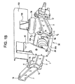
- FIGs. 1A and 1B therein is illustrated an exemplar embodiment of a multi-piece axle according to the subject invention connected to a lift axle suspension (indicated at 30) such as is described in commonly owned U.S. Patent Application No. 10/384,755, entitled IN LINE AXLE SUSPENSION SYSTEM, filed March 11, 2003.
- a lift axle suspension indicated at 30
- the present invention finds particular utility when combined with the "IN LINE" suspension, it is contemplated that the multi-piece axle described herein may be employed with any suspension (including non-lift suspensions) requiring connection to an axle including suspensions not yet known.
- suspension 30 Although suspension 30's precise configuration is not required to be employed to practice the instant invention, it will be described herein for the purposes of highlighting the unique utilities of the inventive axle and its combination therewith. It will be understood, however, that only one side of the suspension will be illustrated for sake of clarity and that the remaining portion of the suspension is simply duplicated on the opposite side of the axle in conventional practice.
- suspension 30 generally comprises a pair of oppositely oriented suspension beam members 32a-b (oriented substantially parallel one to the other in some embodiments) having four pivots P 1-4 (see Fig. 4A) of conventional type (e.g. elastomeric bushing pivots) for maintaining the preferred parallelogram nature of the suspension system. As shown, these pivots are provided for connecting the respective ends of suspension beams 32 a-b to hanger bracket 40 in a known manner as well as to axle seat 1 in a unique configuration as will be described below.
- pivots P 1-4 e.g. elastomeric bushing pivots
- Air bellows 36 is connected at its top end to frame members 105 of the vehicle (via a connecting bracket 106 or in another configuration as needed) and at its bottom end to axle 1 via air bellows seat 34, described in more detail below, which has a unique design and function previously unknown in the art. Assembled in this configuration, air bellows 36 is the primary means for taking up the articulation and load-carrying forces of the suspension experienced during vehicle operation over road surfaces. In addition, air bellows 36 acts in concert with air bellows 38, located between suspension beams 32 a-b, to lift and lower wheeled axle 1 out of and into road engaging positions.
- Figs. 2A-2B these figures are presented merely to illustrate the environment in which axle 1 and suspension 30 find utility.
- vehicle 101 is illustrated in the figures as a generic vehicle and is intended to represent a wide variety of vehicle types including such vehicles as heavy-duty dump trucks, semi-trailers, trailers, mining vehicles, and the like.
- the use of the disclosed axle (and/or suspension) is by no means limited to such environments and thus may be used in conventional passenger vehicles, for example.
- Figs. 2A-B illustrate vehicle 101 having longitudinal frame members 105 carrying a suspension 30 which, as employed as an auxiliary wheeled lift axle suspension, is placed forward of rear axle 103 of a vehicle.
- FIG. 2A shows wheel bearing suspension 30 in its raised, non-load bearing position (tires 107 lifted off of road surface 111).
- Fig. 2B shows wheel bearing suspension 30 in its lowered, road engaging, load bearing position.
- vehicle 101 normally has a forward steerable axle (not shown), as well as a standard rear axle 103 (including tires 109) such that the rear and forward axles (together with wheels and tires) form the primary means of vehicle support such that suspension 30 may be operated to lift its tires 107 off the road.
- axle 1 is of a three-piece design and generally comprises a main beam 3 constructed from a conventional I-beam-type material which forms the central portion of the axle.
- Axle ends 5 and 7 are removably attached at opposite ends of main beam 3 and are provided for carrying a conventional kingpin and wheel assembly which, as conventional parts known to skilled artisans, are not described in detail herein.
- each axle end 5 and 7 includes a kingpin seat for carrying a kingpin for connecting to a conventional steering knuckle.
- axle is formed of three distinct, replaceable pieces, if a kingpin or axle end is damaged, the damaged portion can be independently removed and replaced (or repaired if the circumstances permit) rather than the entire axle and/or suspension thus rendering repairs cheaper and more labor efficient.
- axle ends 5 and 7 which have higher strength requirements than the middle beam, can be constructed of a high-strength, but heavy, steel with beam 3 being constructed of an alloy to conserve weight. In this manner, specific strength and durability requirements for the axle can be met while simultaneously allowing for overall vehicle weight reduction which in turn allows for additional load to be carried and more profit realized.
- each receiving plate 9a-b and each connecting plate 11 and 13 is comprised of a plate member having a plurality of apertures "A" disposed therethrough.
- the shape of the receiving and connecting plates as well as the position (i.e. spacing) of the apertures therein is such that when a connecting plate is mated to a receiving plate the apertures of each align for connection purposes.
- a plurality of additional apertures "A" are provided in the receiving and connecting plates (i.e. more than are required for assembling the axle components together) with each aperture "A" in a vertical column being preferably spaced substantially equally from its adjacent aperture (within the column). This is done, in these embodiments, primarily so that the ride height of the vehicle can be adjusted by simply varying the mating positions of the connecting plates (11, 13) to the receiving plates (9a, 9b). For example, first and second axle ends can be mated, via their connecting plates, to a "low” set of apertures on receiving plates 9a-b thereby to achieve a "high” ride height, or vice versa.
- bolt pairs 15 and 23 are provided which may be inserted through aligned apertures "A" of the connecting and receiving plates, respectively, and then nuts 25 threaded thereon to connect the axle parts to form a single rigid member (see Figs. 3B and 4A-B).
- bolt pairs 15 and 23 uniquely serve two additional functions.
- bolt pair 15 pivotally connects beams 32a and 32b of suspension 30 to axle 1
- bolt pair 23 securely connects airspring seat 34 between the axle end portions 5 and/or 7 and middle beam 3 (via their respective connecting and receiving plates) thereby functionally connecting suspension 30 to axle 1.
- conventional axle seats are rendered unnecessary for connecting a suspension to an axle.
- weight and part numbers are reduced as is the space required to install an auxiliary (or other type) axle.
- axle seats e.g. typically comprising a pair of u-bolts and associated other parts
- the elimination of conventional axle seats provides several distinct benefits including that less weight is used because there are fewer parts employed, less "real estate" under the body of vehicle 101 is used because there is no axle seat to unnecessarily raise the suspension above the height of the axle (e.g.
- the "camber” and “toe” which the axle imparts to the wheels can be adjusted as needed or desired.
- “camber” is defined as the angle of the wheels with respect to vertical
- “toe” is defined as the angle of the wheels with respect to a centerline drawn from the front to the back of the vehicle (e.g. or with respect to the frame rails of the vehicle).
- Figs. 5 and 6 demonstrate exemplar angles of camber and toe, but are not to scale and are primarily intended to illustrate the preferred direction or tilt of the angle rather than a strict numerical value. Such directions of angles are preferred, in this regard, because they are known for producing improved tire wear as well as vehicle “tracking" ability and/or lateral stability. Typical angles employed in conventional practice range from approximately 0-4 degrees for "camber” and approximately 0-2 degrees for "toe”.
- shims "S” may be inserted between receiving plates 9a-9b and connecting plates 11, 13 (see Figs. 7A-7D). More particularly, shims "S” may be added between the front (see Fig. 7A) or rear (see Fig. 7B) portions of the connecting and receiving plates in order to adjust "toe” and/or added between the top (see Fig. 7C) or bottom (see Fig. 7D) portions of the connecting and receiving plates to adjust wheel camber.
- an air reservoir 3' (e.g. a high pressure tank) normally employed for storing compressed gas for selectively pressurizing air bellows 36 and 38 (e.g. for "shifting" the axle into a ground engaging position), replaces (or is integrated into) main beam 3 with the walls of the reservoir forming a structural portion of the axle. Located as such, the reservoir consumes less space under the vehicle, and in addition, reduces overall vehicle weight.
Applications Claiming Priority (2)
| Application Number | Priority Date | Filing Date | Title |
|---|---|---|---|
| US770601 | 2004-02-04 | ||
| US10/770,601 US7510197B2 (en) | 2004-02-04 | 2004-02-04 | Multi-piece axle and suspension |
Publications (3)
| Publication Number | Publication Date |
|---|---|
| EP1564036A2 true EP1564036A2 (fr) | 2005-08-17 |
| EP1564036A3 EP1564036A3 (fr) | 2006-02-08 |
| EP1564036B1 EP1564036B1 (fr) | 2012-01-04 |
Family
ID=34701326
Family Applications (1)
| Application Number | Title | Priority Date | Filing Date |
|---|---|---|---|
| EP04105683A Active EP1564036B1 (fr) | 2004-02-04 | 2004-11-11 | Essieu à pièces multiples et suspension |
Country Status (4)
| Country | Link |
|---|---|
| US (1) | US7510197B2 (fr) |
| EP (1) | EP1564036B1 (fr) |
| CA (1) | CA2485811C (fr) |
| MX (1) | MXPA04011365A (fr) |
Cited By (5)
| Publication number | Priority date | Publication date | Assignee | Title |
|---|---|---|---|---|
| WO2011030073A1 (fr) * | 2009-09-11 | 2011-03-17 | Peugeot Citroën Automobiles SA | Train roulant notamment pour vehicule automobile |
| WO2011034470A1 (fr) * | 2009-09-18 | 2011-03-24 | Volvo Lastvagnar Ab | Console destinée à être fixée sur un châssis de véhicule et véhicule comprenant une console de support de suspension |
| WO2013095207A1 (fr) * | 2011-12-22 | 2013-06-27 | Volvo Lastavagnar Ab | Carter de pont de véhicule et véhicule comprenant un tel carter de pont |
| EP2676821A1 (fr) * | 2012-06-18 | 2013-12-25 | TG Consulting, Besloten Vennootschap met Beperkte Aansprakelijkheid | Jeu de pièces pour l'assemblage d'une suspension de roue, suspension de roue assemblée d'un tel jeu de pièces et procédé d'assemblage pour suspension de roue utilisant un tel jeu de pièces |
| CN104908551A (zh) * | 2014-03-12 | 2015-09-16 | 现代摩比斯株式会社 | 车辆用扭力梁车轴装置 |
Families Citing this family (12)
| Publication number | Priority date | Publication date | Assignee | Title |
|---|---|---|---|---|
| US7152866B2 (en) * | 2004-01-14 | 2006-12-26 | Watson & Chalin Manufacturing, Inc. | Steerable and liftable independent suspension system |
| US7914025B2 (en) * | 2008-03-14 | 2011-03-29 | Jme Enterprises, Inc. | Modular suspension system |
| US8596652B2 (en) * | 2009-05-29 | 2013-12-03 | Lucas Hou-Wae Tong | Battery-powered motorized vehicle with a carrying platform |
| US9290221B2 (en) * | 2013-01-28 | 2016-03-22 | Saf-Holland, Inc. | Auxiliary axle and suspension assembly |
| US9149000B2 (en) * | 2013-03-15 | 2015-10-06 | Kuhn North America, Inc. | Bogie axle for a machine |
| US9849745B2 (en) * | 2013-04-03 | 2017-12-26 | Hendrickson Usa, L.L.C. | Vehicle suspension system with reservoir for air spring damping |
| US9139061B2 (en) * | 2013-04-03 | 2015-09-22 | Watson & Chalin Manufacturing, Inc. | Vehicle suspension system with reservoir for air spring damping |
| US10138966B2 (en) * | 2014-03-11 | 2018-11-27 | Nissin Kogyo Co., Ltd. | Vehicle brake apparatus |
| US9352628B2 (en) * | 2014-05-22 | 2016-05-31 | Ridewell Corporation | Lift suspension system with offset control arms |
| US10293875B2 (en) * | 2017-01-25 | 2019-05-21 | Consolidated Metco, Inc. | Axel lift mechanism |
| US11712938B1 (en) * | 2020-03-03 | 2023-08-01 | Jason M. Klein | Pistonless pneumatic dampening and straight centering for a steerable axle of a heavy-duty vehicle |
| US11794545B1 (en) | 2021-03-29 | 2023-10-24 | Jason M. Klein | Lift axle suspension system for a heavy-duty vehicle, which suspension system uses X-rod control arms for improved lateral stability |
Citations (1)
| Publication number | Priority date | Publication date | Assignee | Title |
|---|---|---|---|---|
| US5403031A (en) | 1993-12-08 | 1995-04-04 | The Boler Company | Parallelogram lift axle suspension system with a control for axle caster adjustment |
Family Cites Families (19)
| Publication number | Priority date | Publication date | Assignee | Title |
|---|---|---|---|---|
| US2072198A (en) * | 1936-05-26 | 1937-03-02 | Davis William Edwin | Spring and spindle bracket |
| US4203617A (en) * | 1978-03-31 | 1980-05-20 | Dana Corporation | Vehicle load supporting structure |
| JPS6047124B2 (ja) | 1980-11-13 | 1985-10-19 | マツダ株式会社 | トレ−リング式リヤサスペンシヨン |
| JP2623864B2 (ja) | 1989-10-18 | 1997-06-25 | 日産自動車株式会社 | 従動輪用リジッドサスペンションのアクスル構造 |
| IT1236484B (it) * | 1989-12-15 | 1993-03-09 | Carraro Spa | Assale sterzante a carreggiata variabile |
| US5409255A (en) * | 1990-08-10 | 1995-04-25 | Benteler Industries, Inc. | Twist beam axle |
| US5037126A (en) * | 1990-09-07 | 1991-08-06 | The Boler Company | Lightweight beam suspension system |
| US5112078A (en) * | 1990-12-21 | 1992-05-12 | Neway Corp. | Axle mounting assembly |
| US5288100A (en) * | 1991-03-14 | 1994-02-22 | Nai Neway, Inc. | Axle support bracket for a drive axle suspension |
| US5326128A (en) * | 1991-09-09 | 1994-07-05 | Csn Manufacturing, Inc. | Variable-width torsion spring axle |
| US5409254A (en) * | 1992-05-11 | 1995-04-25 | A. O. Smith Corporation | Rear suspension with aligned coil springs and twist beam axle |
| US5429423A (en) * | 1994-01-07 | 1995-07-04 | Dana Corporation | Fabricated front axle I-beam |
| US5464243A (en) * | 1995-01-13 | 1995-11-07 | Deere & Company | Adjustable axle with shim structure |
| US5810377A (en) * | 1997-01-21 | 1998-09-22 | The Boler Company | Fabricated steer axle |
| FR2761304B1 (fr) | 1997-03-28 | 1999-06-18 | Peugeot | Train de roues arriere pour vehicule automobile a traverse deformable en torsion |
| US6086162A (en) * | 1998-12-14 | 2000-07-11 | General Motors Corporation | Motor vehicle rear axle and method |
| US6398236B1 (en) * | 1999-07-16 | 2002-06-04 | Holland Neway International, Inc. | Lift axle suspension with axle reservoir |
| US6416136B1 (en) * | 2000-02-23 | 2002-07-09 | Fred P. Smith | Lightweight, adjustable-height, axle |
| US6311993B1 (en) * | 2000-10-18 | 2001-11-06 | Link Mfg., Ltd. | Lift axle suspension mounting system |
-
2004
- 2004-02-04 US US10/770,601 patent/US7510197B2/en active Active
- 2004-10-22 CA CA2485811A patent/CA2485811C/fr active Active
- 2004-11-11 EP EP04105683A patent/EP1564036B1/fr active Active
- 2004-11-16 MX MXPA04011365A patent/MXPA04011365A/es active IP Right Grant
Patent Citations (1)
| Publication number | Priority date | Publication date | Assignee | Title |
|---|---|---|---|---|
| US5403031A (en) | 1993-12-08 | 1995-04-04 | The Boler Company | Parallelogram lift axle suspension system with a control for axle caster adjustment |
Cited By (10)
| Publication number | Priority date | Publication date | Assignee | Title |
|---|---|---|---|---|
| WO2011030073A1 (fr) * | 2009-09-11 | 2011-03-17 | Peugeot Citroën Automobiles SA | Train roulant notamment pour vehicule automobile |
| FR2949997A1 (fr) * | 2009-09-11 | 2011-03-18 | Peugeot Citroen Automobiles Sa | Train roulant notamment pour vehicule automobile |
| WO2011034470A1 (fr) * | 2009-09-18 | 2011-03-24 | Volvo Lastvagnar Ab | Console destinée à être fixée sur un châssis de véhicule et véhicule comprenant une console de support de suspension |
| US8276928B2 (en) | 2009-09-18 | 2012-10-02 | Volvo Lastvagnar Ab | Console for attachment to a vehicle chassis and vehicle comprising a suspension carrying console |
| CN102574438B (zh) * | 2009-09-18 | 2015-03-04 | 沃尔沃拉斯特瓦格纳公司 | 用于附接到车辆底盘的托架和包括悬架携载式托架的车辆 |
| WO2013095207A1 (fr) * | 2011-12-22 | 2013-06-27 | Volvo Lastavagnar Ab | Carter de pont de véhicule et véhicule comprenant un tel carter de pont |
| EP2676821A1 (fr) * | 2012-06-18 | 2013-12-25 | TG Consulting, Besloten Vennootschap met Beperkte Aansprakelijkheid | Jeu de pièces pour l'assemblage d'une suspension de roue, suspension de roue assemblée d'un tel jeu de pièces et procédé d'assemblage pour suspension de roue utilisant un tel jeu de pièces |
| BE1020713A3 (nl) * | 2012-06-18 | 2014-04-01 | Geusens Tony | Montageset voor het samenstellen van een wielophanging, wielophanging samengesteld met behulp van zulke montageset, evenals werkwijze voor het samenstellen van een wielophanging gebruik makende van zulke montageset. |
| CN104908551A (zh) * | 2014-03-12 | 2015-09-16 | 现代摩比斯株式会社 | 车辆用扭力梁车轴装置 |
| CN104908551B (zh) * | 2014-03-12 | 2017-06-23 | 现代摩比斯株式会社 | 车辆用扭力梁车轴装置 |
Also Published As
| Publication number | Publication date |
|---|---|
| US7510197B2 (en) | 2009-03-31 |
| CA2485811C (fr) | 2010-08-24 |
| CA2485811A1 (fr) | 2005-08-04 |
| EP1564036A3 (fr) | 2006-02-08 |
| EP1564036B1 (fr) | 2012-01-04 |
| MXPA04011365A (es) | 2005-08-05 |
| US20050167937A1 (en) | 2005-08-04 |
Similar Documents
| Publication | Publication Date | Title |
|---|---|---|
| CA2485811C (fr) | Essieu multi-pieces et suspension | |
| CA2538599C (fr) | Essieu rigide destine a un vehicule et comprenant des bras longitudinaux monoblocs | |
| US6416069B1 (en) | Underbeam axle lift assembly | |
| US5996981A (en) | Reduced size bushing for beam-type axle suspension system | |
| US10569814B2 (en) | Lift axle auxiliary suspension systems | |
| US6880839B2 (en) | In-line lift axle suspension system | |
| EP0747262B1 (fr) | Système de suspension et caisse pour camion de grande taille à benne basculante | |
| US4792148A (en) | Semi-trailer truck | |
| US8459666B2 (en) | Side-beam lift assembly for heavy-duty vehicles | |
| US20040036245A1 (en) | Suspension system and body for large dump trucks | |
| US7198298B2 (en) | Movable subframe for semi-trailers | |
| US20060158023A1 (en) | Continuous radius axle and fabricated spindle assembly | |
| AU650233B2 (en) | Large dump truck | |
| US6883813B2 (en) | Independent paddle lift axle suspension system | |
| US11794545B1 (en) | Lift axle suspension system for a heavy-duty vehicle, which suspension system uses X-rod control arms for improved lateral stability | |
| MXPA93006307A (en) | Axle suspension system for overhead vehicles |
Legal Events
| Date | Code | Title | Description |
|---|---|---|---|
| PUAI | Public reference made under article 153(3) epc to a published international application that has entered the european phase |
Free format text: ORIGINAL CODE: 0009012 |
|
| 17P | Request for examination filed |
Effective date: 20041111 |
|
| AK | Designated contracting states |
Kind code of ref document: A2 Designated state(s): AT BE BG CH CY CZ DE DK EE ES FI FR GB GR HU IE IS IT LI LU MC NL PL PT RO SE SI SK TR |
|
| AX | Request for extension of the european patent |
Extension state: AL HR LT LV MK YU |
|
| PUAL | Search report despatched |
Free format text: ORIGINAL CODE: 0009013 |
|
| AK | Designated contracting states |
Kind code of ref document: A3 Designated state(s): AT BE BG CH CY CZ DE DK EE ES FI FR GB GR HU IE IS IT LI LU MC NL PL PT RO SE SI SK TR |
|
| AX | Request for extension of the european patent |
Extension state: AL HR LT LV MK YU |
|
| AKX | Designation fees paid |
Designated state(s): DE FR GB IT TR |
|
| 17Q | First examination report despatched |
Effective date: 20071015 |
|
| GRAP | Despatch of communication of intention to grant a patent |
Free format text: ORIGINAL CODE: EPIDOSNIGR1 |
|
| GRAS | Grant fee paid |
Free format text: ORIGINAL CODE: EPIDOSNIGR3 |
|
| GRAA | (expected) grant |
Free format text: ORIGINAL CODE: 0009210 |
|
| AK | Designated contracting states |
Kind code of ref document: B1 Designated state(s): DE FR GB IT TR |
|
| REG | Reference to a national code |
Ref country code: GB Ref legal event code: FG4D |
|
| REG | Reference to a national code |
Ref country code: DE Ref legal event code: R096 Ref document number: 602004035951 Country of ref document: DE Effective date: 20120301 |
|
| PLBE | No opposition filed within time limit |
Free format text: ORIGINAL CODE: 0009261 |
|
| STAA | Information on the status of an ep patent application or granted ep patent |
Free format text: STATUS: NO OPPOSITION FILED WITHIN TIME LIMIT |
|
| 26N | No opposition filed |
Effective date: 20121005 |
|
| REG | Reference to a national code |
Ref country code: DE Ref legal event code: R097 Ref document number: 602004035951 Country of ref document: DE Effective date: 20121005 |
|
| REG | Reference to a national code |
Ref country code: FR Ref legal event code: PLFP Year of fee payment: 12 |
|
| REG | Reference to a national code |
Ref country code: FR Ref legal event code: PLFP Year of fee payment: 13 |
|
| REG | Reference to a national code |
Ref country code: FR Ref legal event code: PLFP Year of fee payment: 14 |
|
| PGFP | Annual fee paid to national office [announced via postgrant information from national office to epo] |
Ref country code: GB Payment date: 20231121 Year of fee payment: 20 |
|
| PGFP | Annual fee paid to national office [announced via postgrant information from national office to epo] |
Ref country code: TR Payment date: 20231031 Year of fee payment: 20 Ref country code: IT Payment date: 20231107 Year of fee payment: 20 Ref country code: FR Payment date: 20231123 Year of fee payment: 20 Ref country code: DE Payment date: 20231127 Year of fee payment: 20 |