EP1563965A1 - Ensemble de rangement pour véhicules utilitaires composé d'un nombre évolutif de racks et de mallettes - Google Patents
Ensemble de rangement pour véhicules utilitaires composé d'un nombre évolutif de racks et de mallettes Download PDFInfo
- Publication number
- EP1563965A1 EP1563965A1 EP05002232A EP05002232A EP1563965A1 EP 1563965 A1 EP1563965 A1 EP 1563965A1 EP 05002232 A EP05002232 A EP 05002232A EP 05002232 A EP05002232 A EP 05002232A EP 1563965 A1 EP1563965 A1 EP 1563965A1
- Authority
- EP
- European Patent Office
- Prior art keywords
- racks
- rack
- referenced globally
- case
- stackable
- Prior art date
- Legal status (The legal status is an assumption and is not a legal conclusion. Google has not performed a legal analysis and makes no representation as to the accuracy of the status listed.)
- Granted
Links
Images



Classifications
-
- A—HUMAN NECESSITIES
- A47—FURNITURE; DOMESTIC ARTICLES OR APPLIANCES; COFFEE MILLS; SPICE MILLS; SUCTION CLEANERS IN GENERAL
- A47B—TABLES; DESKS; OFFICE FURNITURE; CABINETS; DRAWERS; GENERAL DETAILS OF FURNITURE
- A47B87/00—Sectional furniture, i.e. combinations of complete furniture units, e.g. assemblies of furniture units of the same kind such as linkable cabinets, tables, racks or shelf units
- A47B87/02—Sectional furniture, i.e. combinations of complete furniture units, e.g. assemblies of furniture units of the same kind such as linkable cabinets, tables, racks or shelf units stackable ; stackable and linkable
- A47B87/0207—Stackable racks, trays or shelf units
-
- B—PERFORMING OPERATIONS; TRANSPORTING
- B25—HAND TOOLS; PORTABLE POWER-DRIVEN TOOLS; MANIPULATORS
- B25H—WORKSHOP EQUIPMENT, e.g. FOR MARKING-OUT WORK; STORAGE MEANS FOR WORKSHOPS
- B25H3/00—Storage means or arrangements for workshops facilitating access to, or handling of, work tools or instruments
- B25H3/02—Boxes
- B25H3/021—Boxes comprising a number of connected storage elements
- B25H3/022—Boxes comprising a number of connected storage elements in fixed relationship
-
- B—PERFORMING OPERATIONS; TRANSPORTING
- B25—HAND TOOLS; PORTABLE POWER-DRIVEN TOOLS; MANIPULATORS
- B25H—WORKSHOP EQUIPMENT, e.g. FOR MARKING-OUT WORK; STORAGE MEANS FOR WORKSHOPS
- B25H3/00—Storage means or arrangements for workshops facilitating access to, or handling of, work tools or instruments
- B25H3/02—Boxes
- B25H3/021—Boxes comprising a number of connected storage elements
- B25H3/023—Boxes comprising a number of connected storage elements movable relative to one another for access to their interiors
- B25H3/028—Boxes comprising a number of connected storage elements movable relative to one another for access to their interiors by sliding extraction from within a common frame
Definitions
- the present invention relates to a storage unit for vehicles Utilities, consisting of an evolving number of racks and briefcases.
- Patent FR 2 609 610 Storage cabinet with drawers. This patent describes a set of storage drawers mounted, sliding in the frame. This frame consists of frames (1) which are stackable by means of interlocking (2b, 2f).
- Patent DE 23 29 016 paper, das austiciann gleichen Elementen Wooltalk ist, - - salmon aus Kunststoff.
- This patent describes a piece of furniture composed of several elements (1) having the form of strips folded in U assembled together by clipping and pinning. The elements have on their inner faces parallel ribs (6) or reinforcing strips (30) (31) for receiving tablets (25) or rails with sliding parts (54).
- U.S. Patent 3,003,839 Display tray assembly. This patent describes joining elements which can be joined to one another by means of interlocking to click. This engagement is achieved by exercising a certain effort on the upper element that comes to hang with the lower element.
- GB Patent 679,948 Improvements relating to Sectional Metal Cabinets and like Sectional Furniture.
- This patent describes a piece of furniture comprising stackable frames.
- Each frame (B) (C) has housings can contain several drawers. Springs (22) as well as transverse bars (26) prevent the drawers from being able to disengage chassis (B) (C).
- Patent FR 2 223 948 Set of furniture elements to assemble. This patent describes a set of furniture elements comprising bins open on one side, stackable and juxtaposed, intended to receive drawers whose output is deliberately limited by a stop.
- the present invention discloses a vehicle storage assembly utilities, consisting of three main parts, a set of racks, cases, a base and fixing brackets.
- the racks are stackable and solidarisable elements between them by means of fasteners such as bolts, among others.
- These racks are rectangular bowl-shaped with one side of a weak height which will be called edge before.
- the other vertical sides have horizontal lips overflowing, identical, each pierced in a way similar holes required for the passage of fasteners for assemble the racks together.
- These rack sets are completed in low and high parts by two pieces, of identical shape, titled support racks and lid.
- This rack of racks and this lid, of form identical, can be fixed to the racks by means of fasteners such as bolts, among others.
- This rack support is shaped like rectangular bowl whose back and both sides have a lip horizontal overflowing.
- the lid also has a horizontal lip overflowing.
- the flowing horizontal lip is pierced with orifices necessary for the passage of the fasteners to assemble the support from racks and the lid to the racks.
- This rack holder and this lid are also consist of bosses to receive the spring of compression and recesses favoring the release of the compression spring solidary of the bottom of rack.
- This set of racks can be secured to a vehicle floor or other by means of a rectangular bottom plate, integral with the rack support by means of fasteners such as studs, between other.
- This rectangular bottom plate is housed in the slide on three sides. This arrangement makes it possible to remove the set of racks from the floor of the vehicle thus releasing the useful surface and volume if necessary.
- This set of racks arranged in the slide can also be fixed on the vertical walls of a vehicle by means of fixing brackets adjustable in length to compensate for side variations between the set of racks and the curve of the walls of the vehicle.
- this set of racks consists of the number of racks that we desire, storage cases at hardware store or other come slip horizontally in each compartment materialized by each rack. These cases are held in place by the front edge of low height and a compression spring located on the inner rear face of the rack; it ensures permanent maintenance of the briefcase with the front edge of the rack. On the other hand, these briefcases are also kept pressed against the bottom of the racks by a compression spring located under the bottom of the upper rack. To extract the case from its compartment, the user takes it by its handle and raises it slightly obliquely; operation that then compresses the compression spring located on the bottom of the upper rack. The case can then be extracted. The recesses the rack support allows to receive the compression spring when his upper rack is assembled on, while the bosses of the cover receive a compression spring when its lower rack is assembled below.
- Each case is equipped with a label on the front that can specify the nature of the objects stored in it.
- a record in the back of the briefcase organize the storage in each compartment by specifying the nature of the room and the approximate amount that can be accommodated.
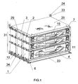
- FIG. 1 represents, in perspective, the device of the present invention assembled.
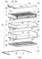
- FIG. 2 represents, in perspective, an exploded view of the device of the present invention, with a briefcase.
- Figure 3 shows, in section, a rack.
- FIG. 4 represents the bottom view of a rack with spring compression.
- FIG. 5 represents the bottom view of the lid or a support racks.
- FIG. 6 represents, in perspective, a briefcase in its position opened.
- FIG. 7 represents, in perspective, a briefcase in its position closed.
- Figure 8 shows, in section, the locking device of the cases.
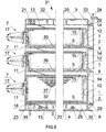
- FIG. 9 represents, in section, the extraction of the cases from their racks.
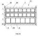
- FIG. 10 represents, in section, the blocking device of the present invention in lateral position and in vertical position.
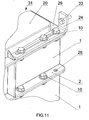
- FIG. 11 represents, in section, the longitudinal locking device in the minimum position of the present invention.
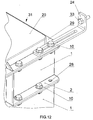
- Figure 12 shows, in section, the longitudinal locking device in the maximum position of the present invention.
- the device consists of stackable racks (1) shaped rectangular bowl open on its upper part and on its front side.
- the front of the rack (1) is closed on a low height by a front edge (11).
- the other two lateral sides of the rack (1) and its internal rear face (9) forming a U comprise, in their upper part, an overflowing horizontal lip (3) and, in their part lower, an overflowing horizontal lip (2).
- the inner back (9) one of the racks (1) has a compression spring (12).
- the bottom (5) racks (1) serves as support for the case (7) and has, in its outer face, a compression spring (13).
- the outer face of the bottom (5) of the racks (1) consists of ribs (8) in the form of a grid.
- the ribs (8) serve as stiffeners for the racks (1).
- the ribs (8) are closed, on three sides, at their periphery by an overflowing horizontal lip (2).
- the overflowing horizontal lip (3) and the horizontal lip flowing (2) identical, are pierced, each in a similar manner, with orifices (26). These holes (26) allow the passage of fasteners such as bolts (10) among others.
- the assembly of the racks (1) between them is obtained by placing the overlying horizontal lip (2) of the rack in position (1) Upper with the overflowing horizontal lip (3) of the lower rack (1).
- This setting in position is aided by the centering of the cylindrical lugs (27) located on the overflowing horizontal lip (2) of the rack (1).
- the cylindrical lugs (27) are centered with the axis of the holes (28) which are positioned on the overflowing horizontal lip (3).
- the racks (1) are immobilizable between them by means of fasteners such as bolts (10) among others.
- the assembly comprises several racks (1) which are terminated at the bottom by a rack support (4) and partly high by a cover (20), of identical shape.
- This rack support (4) is shaped rectangular bowl (30) open on its upper part of which the back and both sides have an overflowing horizontal lip (29) U-shaped.
- the lid (20) also has a lip horizontal overflowing (29) U-shaped.
- the horizontal lip overflowing (29) is pierced with orifices (26). These orifices (26) allow the passage of elements fasteners such as bolts (10) among others.
- Inside the rectangular bowl (30) consists of ribs (32).
- the bosses (21) are intended for fixing the compression spring (13) under the lid (20).
- the recesses (22) of the rack support (4) are intended to provide the passage of the compression spring (13) provided under the bottom (5) of the rack (1).
- the assembly of the rack support (4) with respect to the rack (1) is obtained by positioning the overflowing horizontal lip (2) of the rack (1) with the overflowing horizontal lip (29) of the rack support (4). This implementation position is assisted by the centering of the cylindrical lugs (27) located on the horizontal lip overflowing (2) of the rack (1).
- the cylindrical lugs (27) are centered with the axis of the holes (28) which are positioned on the lip horizontal overflowing (29).
- the rack support (4) and the rack (1) upper are immobilisable together by means of fasteners such as bolts (10) among others.
- the assembly of the cover (20) with respect to the rack (1) is obtained by positioning the overlying horizontal lip (29) of the cover (20) with the overflowing horizontal lip (3) of the rack (1) at the top of the assembly.
- the cover (20) and said rack (1) are immobilizable with each other at means of fasteners such as bolts (10) among others.
- the device comprises a rectangular bottom plate (23) which is attached to the underside of the rack support (4) at means of fasteners such as studs (25) among others.
- the plaque Rectangular bottom (23) protrudes slightly from the lower contour of the rack support (4); this overtaking thus forming a horizontal lip overflowing.
- the assembly (31) in order to prevent the assembly (31) from moving when it is placed in a moving vehicle, the assembly (31) must be immobilized in a horizontal and vertical plane. This immobilization is carried out by via a slide (6) and by fixing brackets (24). All (31) slides through the rectangular bottom plate (23), between the slide (6) and the ground. The assembly (31) is thus blocked in the lateral direction of the horizontal and vertical planes.
- the fastening brackets (24) allow blocking the assembly (31) on the walls of the vehicle.
- Fixing brackets (24) are longitudinally adjustable thanks to their oblong holes.
- the fixing brackets (24) are positioned indifferently on the lip horizontal overflowing (29) of the cover (20) is on the horizontal lip overflowing (2) of the rack (1).
- the fastening brackets (24) allow their settings, to compensate for the variations of odds between the set (31) and the curve of the walls of the vehicle. After adjusting the fixing brackets (24), the latter are immobilizable relative to the cover (20) or to the rack (1) by means of fasteners such as bolts (10) between other.
- the fixing brackets (24) can be taken directly back either on the body, either on a rail by means of fasteners such as bolts (33) among others.
- the assembly (31) consists of the evolutionary number racks (1) as needed. Cases (7) are housed horizontally in each rack (1). Locking a case (7) in its rack (1) is provided in two directions: a horizontal and a vertical.
- each case (7) consists of a bottom (14), a lid (15), removable lockers (35) (36) or removable partitions (37).
- Each case (7) has on its front face, extensions (18) and is equipped with a label (19) on the front that can specify the nature of the objects stored in it.
- a notice (16) is located between the bottom (14) and either the removable lockers (35) (36) or removable partitions (37), among others. This notice (16) organizes the storage of each compartment, specifying the nature of the room and approximate amount that can be accommodated.
- the compression spring (12) integral with the inner rear face (9) the rack (1) ensures the horizontal locking by its action on the case (7) in pushing it to the front edge (11) of the bottom of the rack (1) thus bringing the extensions (18) of the case in contact with said front flange (11).
- the extraction of the case (7) from its rack is carried out by the user when the latter takes the handle (17) of the case (7) and slightly raises the case (7) until the latter is above the front edge (11) of the rack (1). This action compresses the spring compression (13). The user can then pull the case (7) towards him.
- the briefcase (7) slides on its bottom (14) on the front edge (11) which ends the bottom (5) of the rack (1). This action is helped initially by the push compression spring (12).
- the case (7) is extracted from its rack (1).
Landscapes
- Engineering & Computer Science (AREA)
- Mechanical Engineering (AREA)
- Purses, Travelling Bags, Baskets, Or Suitcases (AREA)
- Vehicle Step Arrangements And Article Storage (AREA)
- Containers Having Bodies Formed In One Piece (AREA)
- Details Of Rigid Or Semi-Rigid Containers (AREA)
- Combinations Of Kitchen Furniture (AREA)
- Pallets (AREA)
- Assembled Shelves (AREA)
Abstract
Description
Claims (10)
- Ensemble de rangement pour véhicules utilitaires, composé d'un nombre évolutif de racks référencés globalement en (1), en forme de cuvette rectangulaire ouverte sur sa partie supérieure et sur sa face avant, superposables, recevant chacun horizontalement une mallette référencée globalement en (7), caractérisé en ce que les deux côtés latéraux du rack (1) et sa face arrière interne (9) formant un U, comportent sur leur bord supérieur une lèvre horizontale débordante (3) et sur leur bord inférieur une lèvre horizontale débordante (2), identiques, percées chacune d'une façon similaire d'orifices (26) destinés à recevoir des boulons (10) de façon à solidariser entre eux les racks (1) superposés et dont la mise en position sur un plan strictement vertical est facilitée au moyen d'ergots cylindriques (27) prévus sur la lèvre horizontale débordante (2) du rack situé au-dessus et venant se placer dans l'axe des trous (28) prévus sur la lèvre horizontale débordante (3) du rack (1) situé dessous.
- Ensemble de rangement pour véhicules utilitaires, composé d'un nombre évolutif de racks référencés globalement en (1), en forme de cuvette rectangulaire ouverte sur sa partie supérieure et sur sa face avant, superposables, recevant chacun horizontalement une mallette référencée globalement en (7), suivant revendication 1, caractérisé en ce que la face avant du rack (1) est refermée à sa base inférieure sur une faible hauteur, par un rebord avant (11).
- Ensemble de rangement pour véhicules utilitaires, composé d'un nombre évolutif de racks référencés globalement en (1), en forme de cuvette rectangulaire ouverte sur sa partie supérieure et sur sa face avant, superposables, recevant chacun horizontalement une mallette référencée globalement en (7), suivant revendication 1, caractérisé en ce que la face arrière interne (9) du rack (1) comporte un ressort de compression (12) et la face extérieure du fond (5) du rack (1) un autre ressort de compression (13).
- Ensemble de rangement pour véhicules utilitaires, composé d'un nombre évolutif de racks référencés globalement en (1), en forme de cuvette rectangulaire ouverte sur sa partie supérieure et sur sa face avant, superposables, recevant chacun horizontalement une mallette référencée globalement en (7), suivant revendication 1, caractérisé en ce que l'ensemble des racks (1) superposés et solidarisés entre eux, sont terminés en partie basse par un support de racks (4) et en partie haute par un couvercle (20), de forme identique.
- Ensemble de rangement pour véhicules utilitaires, composé d'un nombre évolutif de racks référencés globalement en (1), en forme de cuvette rectangulaire ouverte sur sa partie supérieure et sur sa face avant, superposables, recevant chacun horizontalement une mallette référencée globalement en (7), suivant revendications 1 et 4, caractérisé en ce que le support de racks (4) est en forme de cuvette rectangulaire (30) ouverte sur la face supérieure et dont l'arrière et les deux côtés latéraux comportent une lèvre horizontale débordante (29) en forme de U. Le couvercle (20) comporte également une lèvre horizontale débordante (29) en forme de U. La lèvre horizontale débordante (29) est percée d'orifices (26) qui viennent, pour le support de racks (4), se placer dans l'axe des orifices (26) de la lèvre horizontale débordante (2) du rack (1) situé en bas de l'ensemble (31) et, pour le couvercle (20) dont la lèvre horizontale débordante (29) est également percée d'orifices (26), se placer dans l'axe des orifices (26) de la lèvre horizontale débordante (3) du rack (1) situé en haut de l'ensemble ; les dits orifices étant alors en position pour recevoir les boulons (10) entre autres.
- Ensemble de rangement pour véhicules utilitaires, composé d'un nombre évolutif de racks référencés globalement en (1), en forme de cuvette rectangulaire ouverte sur sa partie supérieure et sur sa face avant, superposables, recevant chacun horizontalement une mallette référencée globalement en (7), suivant revendications 1, 3, 4 et 5, caractérisé en ce que le couvercle (20) et le support de racks (4) de forme identique, en fonction support, le support de racks (4) comporte dans la cuvette rectangulaire (30) des évidements (22) destinés à assurer le passage du ressort de compression (13) prévu sous le fond (5) du rack (1) et d'autre part, en fonction couvercle, le couvercle (20) comporte des bossages (21) destinés à la fixation du ressort de compression (13).
- Ensemble de rangement pour véhicules utilitaires, composé d'un nombre évolutif de racks référencés globalement en (1), en forme de cuvette rectangulaire ouverte sur sa partie supérieure et sur sa face avant, superposables, recevant chacun horizontalement une mallette référencée globalement en (7), suivant revendications 1, 4 et 5, caractérisé en ce que l'ensemble (31) composé de racks (1) terminés en bas par le support de racks (4) peut être solidarisé sur un plancher de véhicule au moyen d'une plaque de fond rectangulaire (23), dont le contour comporte une lèvre débordante par rapport au support de racks (4) venant se loger sur trois de ses côtés dans la glissière (6) solidaire du plancher du véhicule au moyen d'éléments de fixation telles que des vis (34) entre autres.
- Ensemble de rangement pour véhicules utilitaires, composé d'un nombre évolutif de racks référencés globalement en (1), en forme de cuvette rectangulaire ouverte sur sa partie supérieure et sur sa face avant, superposables, recevant chacun horizontalement une mallette référencée globalement en (7), suivant revendications 1, 4 et 5, caractérisé en ce que l'immobilisation parfaite de l'ensemble (31) dans un véhicule, par exemple, et ce, quel que soit le galbe des parois latérales du véhicule à équiper, est obtenue au moyen d'équerres de fixation (24) réglables longitudinalement reliant l'ensemble (31) à la paroi du véhicule.
- Ensemble de rangement pour véhicules utilitaires, composé d'un nombre évolutif de racks référencés globalement en (1), en forme de cuvette rectangulaire ouverte sur sa partie supérieure et sur sa face avant, superposables, recevant chacun horizontalement une mallette référencée globalement en (7), suivant revendication 1, caractérisé en ce que chaque mallette (7) est constituée d'un fond (14), d'un couvercle (15), de casiers amovibles (35) (36) ou encore de cloisons amovibles (37).
- Ensemble de rangement pour véhicules utilitaires, composé d'un nombre évolutif de racks référencés globalement en (1), en forme de cuvette rectangulaire ouverte sur sa partie supérieure et sur sa face avant, superposables, recevant chacun horizontalement une mallette référencée globalement en (7), suivant revendications 1 et 9, caractérisé en ce que chaque mallette (7) est pourvue, sur sa face avant extérieure, d'une étiquette (19) indiquant la nature des objets contenus dans celle-ci. De même, une notice (16), insérée entre le fond (14) de la mallette (7) et soit les casiers amovibles (35) (36) soit les cloisons amovibles (37), précise la nature et la quantité des pièces logées.
Applications Claiming Priority (2)
| Application Number | Priority Date | Filing Date | Title |
|---|---|---|---|
| FR0401638A FR2866291B1 (fr) | 2004-02-17 | 2004-02-17 | Ensemble de rangement pour vehicules utilitaires compose d'un nombre evolutif de racks et de mallettes |
| FR0401638 | 2004-02-17 |
Publications (2)
| Publication Number | Publication Date |
|---|---|
| EP1563965A1 true EP1563965A1 (fr) | 2005-08-17 |
| EP1563965B1 EP1563965B1 (fr) | 2006-12-06 |
Family
ID=34685036
Family Applications (1)
| Application Number | Title | Priority Date | Filing Date |
|---|---|---|---|
| EP05002232A Expired - Lifetime EP1563965B1 (fr) | 2004-02-17 | 2005-02-03 | Ensemble de rangement pour véhicules utilitaires composé d'un nombre évolutif de racks et de mallettes |
Country Status (6)
| Country | Link |
|---|---|
| EP (1) | EP1563965B1 (fr) |
| AT (1) | ATE347470T1 (fr) |
| DE (1) | DE602005000303T2 (fr) |
| ES (1) | ES2276354T3 (fr) |
| FR (1) | FR2866291B1 (fr) |
| PT (1) | PT1563965E (fr) |
Cited By (19)
| Publication number | Priority date | Publication date | Assignee | Title |
|---|---|---|---|---|
| WO2009118554A1 (fr) * | 2008-03-25 | 2009-10-01 | John Francis Collins | Appareil pour transporter des articles |
| WO2011110559A1 (fr) * | 2010-03-09 | 2011-09-15 | Metabowerke Gmbh | Système de valise |
| FR2971445A1 (fr) * | 2011-02-16 | 2012-08-17 | Gerlon Sa | Ensemble de bricolage comprenant un meuble a tiroirs et une valisette |
| USD670495S1 (en) | 2010-10-14 | 2012-11-13 | Plaston Ag | Case with detachable auxiliary cases |
| WO2013075945A3 (fr) * | 2011-11-22 | 2013-07-18 | Robert Bosch Gmbh | Dispositif de fixation pour mallette d'outil à main |
| WO2013075956A3 (fr) * | 2011-11-22 | 2013-07-25 | Robert Bosch Gmbh | Dispositif de fixation pour mallette d'outil à main |
| WO2013075941A3 (fr) * | 2011-11-22 | 2013-07-25 | Robert Bosch Gmbh | Dispositif de fixation pour mallette d'outil à main |
| WO2013075943A3 (fr) * | 2011-11-22 | 2013-08-01 | Robert Bosch Gmbh | Dispositif de fixation pour mallette d'outil à main |
| US8657307B2 (en) | 2011-06-22 | 2014-02-25 | The Stanley Works Israel Ltd. | Modular rolling container assembly |
| EP2226163A3 (fr) * | 2009-03-04 | 2014-11-05 | Stanley Black & Decker, Inc. | Système de conteneur |
| WO2016165901A1 (fr) * | 2015-04-14 | 2016-10-20 | Adolf Würth GmbH & Co. KG | Boîte d'assortiment et ensemble comportant au moins une boîte d'assortiment et une bande de retenue |
| CN108098722A (zh) * | 2017-11-29 | 2018-06-01 | 陈英蔚 | 一种保护性更好的五金部件存储装置 |
| EP3421187A1 (fr) * | 2017-06-29 | 2019-01-02 | HILTI Aktiengesellschaft | Mallette d'accessoires |
| CN110900548A (zh) * | 2018-06-01 | 2020-03-24 | Ftc欧洲有限责任公司 | 工具箱 |
| USD899087S1 (en) | 2015-07-24 | 2020-10-20 | Tts Tooltechnic Systems Ag & Co. Kg | Storage box |
| US20220322826A1 (en) * | 2021-04-09 | 2022-10-13 | Advantus, Corp. | Configurable literature organizer |
| US11780075B2 (en) | 2019-11-26 | 2023-10-10 | Milwaukee Electric Tool Corporation | Securing compartments for modular storage |
| US12005565B2 (en) | 2020-12-07 | 2024-06-11 | Milwaukee Electric Tool Corporation | Sliding rotating storage unit |
| US12514365B2 (en) | 2022-03-22 | 2026-01-06 | Milwaukee Electric Tool Corporation | Slidable support structure for modular units |
Families Citing this family (5)
| Publication number | Priority date | Publication date | Assignee | Title |
|---|---|---|---|---|
| DK2913160T3 (en) * | 2009-12-23 | 2018-08-20 | Essve Produkter Ab | MODULE SYSTEM INCLUDING A HOUSE AND NUMBER OF BOXES |
| USD803560S1 (en) | 2015-07-24 | 2017-11-28 | Tts Tooltechnic Systems Ag & Co. Kg | Storage box |
| DE102018127693B4 (de) * | 2018-11-06 | 2025-10-02 | Bott GmbH & Co. KG | Transportbehälter zur Aufnahme von Werkzeug und Material, Transportbehältersystem und Regal-Behälter-System |
| US11884456B2 (en) | 2020-09-25 | 2024-01-30 | Techtronic Cordless Gp | Tool storage system |
| US20240143048A1 (en) * | 2022-10-27 | 2024-05-02 | Techtronic Cordless Gp | Slotted storage system |
Citations (5)
| Publication number | Priority date | Publication date | Assignee | Title |
|---|---|---|---|---|
| US3003839A (en) * | 1958-09-08 | 1961-10-10 | Universal Dental Company | Display tray assembly |
| CA1120526A (fr) * | 1979-05-08 | 1982-03-23 | Meilleures Specialites De Couture Ltee | Systeme a tiroirs de rangement empilables |
| US4988003A (en) * | 1990-02-14 | 1991-01-29 | A-Bee Syndicate, Inc. | Stackable tray carrying units |
| WO1997035500A1 (fr) * | 1996-03-28 | 1997-10-02 | Oasis Leisure Products Limited | Systeme de rangement |
| US6578937B1 (en) * | 2000-10-04 | 2003-06-17 | Fred Thoman | Stacking toolbox |
-
2004
- 2004-02-17 FR FR0401638A patent/FR2866291B1/fr not_active Expired - Lifetime
-
2005
- 2005-02-03 EP EP05002232A patent/EP1563965B1/fr not_active Expired - Lifetime
- 2005-02-03 AT AT05002232T patent/ATE347470T1/de active
- 2005-02-03 PT PT05002232T patent/PT1563965E/pt unknown
- 2005-02-03 ES ES05002232T patent/ES2276354T3/es not_active Expired - Lifetime
- 2005-02-03 DE DE602005000303T patent/DE602005000303T2/de not_active Expired - Lifetime
Patent Citations (5)
| Publication number | Priority date | Publication date | Assignee | Title |
|---|---|---|---|---|
| US3003839A (en) * | 1958-09-08 | 1961-10-10 | Universal Dental Company | Display tray assembly |
| CA1120526A (fr) * | 1979-05-08 | 1982-03-23 | Meilleures Specialites De Couture Ltee | Systeme a tiroirs de rangement empilables |
| US4988003A (en) * | 1990-02-14 | 1991-01-29 | A-Bee Syndicate, Inc. | Stackable tray carrying units |
| WO1997035500A1 (fr) * | 1996-03-28 | 1997-10-02 | Oasis Leisure Products Limited | Systeme de rangement |
| US6578937B1 (en) * | 2000-10-04 | 2003-06-17 | Fred Thoman | Stacking toolbox |
Cited By (28)
| Publication number | Priority date | Publication date | Assignee | Title |
|---|---|---|---|---|
| WO2009118554A1 (fr) * | 2008-03-25 | 2009-10-01 | John Francis Collins | Appareil pour transporter des articles |
| EP2226163A3 (fr) * | 2009-03-04 | 2014-11-05 | Stanley Black & Decker, Inc. | Système de conteneur |
| WO2011110559A1 (fr) * | 2010-03-09 | 2011-09-15 | Metabowerke Gmbh | Système de valise |
| CN102791438A (zh) * | 2010-03-09 | 2012-11-21 | 麦太保有限公司 | 提箱系统 |
| USD670495S1 (en) | 2010-10-14 | 2012-11-13 | Plaston Ag | Case with detachable auxiliary cases |
| FR2971445A1 (fr) * | 2011-02-16 | 2012-08-17 | Gerlon Sa | Ensemble de bricolage comprenant un meuble a tiroirs et une valisette |
| US8657307B2 (en) | 2011-06-22 | 2014-02-25 | The Stanley Works Israel Ltd. | Modular rolling container assembly |
| WO2013075943A3 (fr) * | 2011-11-22 | 2013-08-01 | Robert Bosch Gmbh | Dispositif de fixation pour mallette d'outil à main |
| US10270288B2 (en) | 2011-11-22 | 2019-04-23 | Robert Bosch Gmbh | Hand tool case holding device |
| WO2013075941A3 (fr) * | 2011-11-22 | 2013-07-25 | Robert Bosch Gmbh | Dispositif de fixation pour mallette d'outil à main |
| CN103945991A (zh) * | 2011-11-22 | 2014-07-23 | 罗伯特·博世有限公司 | 手持式工具箱子保持装置 |
| WO2013075956A3 (fr) * | 2011-11-22 | 2013-07-25 | Robert Bosch Gmbh | Dispositif de fixation pour mallette d'outil à main |
| US9724821B2 (en) | 2011-11-22 | 2017-08-08 | Robert Bosch Gmbh | Hand tool case holding device |
| WO2013075945A3 (fr) * | 2011-11-22 | 2013-07-18 | Robert Bosch Gmbh | Dispositif de fixation pour mallette d'outil à main |
| US10027188B2 (en) | 2011-11-22 | 2018-07-17 | Robert Bosch Gmbh | Hand tool case holding device |
| US10312707B2 (en) | 2011-11-22 | 2019-06-04 | Robert Bosch Gmbh | Hand tool case holding device |
| WO2016165901A1 (fr) * | 2015-04-14 | 2016-10-20 | Adolf Würth GmbH & Co. KG | Boîte d'assortiment et ensemble comportant au moins une boîte d'assortiment et une bande de retenue |
| USD899087S1 (en) | 2015-07-24 | 2020-10-20 | Tts Tooltechnic Systems Ag & Co. Kg | Storage box |
| WO2019002021A1 (fr) * | 2017-06-29 | 2019-01-03 | Hilti Aktiengesellschaft | Mallette à accessoires |
| EP3421187A1 (fr) * | 2017-06-29 | 2019-01-02 | HILTI Aktiengesellschaft | Mallette d'accessoires |
| CN108098722A (zh) * | 2017-11-29 | 2018-06-01 | 陈英蔚 | 一种保护性更好的五金部件存储装置 |
| CN110900548A (zh) * | 2018-06-01 | 2020-03-24 | Ftc欧洲有限责任公司 | 工具箱 |
| US11780075B2 (en) | 2019-11-26 | 2023-10-10 | Milwaukee Electric Tool Corporation | Securing compartments for modular storage |
| US12005565B2 (en) | 2020-12-07 | 2024-06-11 | Milwaukee Electric Tool Corporation | Sliding rotating storage unit |
| US12343857B2 (en) | 2020-12-07 | 2025-07-01 | Milwaukee Electric Tool Corporation | Sliding rotating storage unit |
| US20220322826A1 (en) * | 2021-04-09 | 2022-10-13 | Advantus, Corp. | Configurable literature organizer |
| US11844430B2 (en) * | 2021-04-09 | 2023-12-19 | Advantus, Corp. | Configurable literature organizer |
| US12514365B2 (en) | 2022-03-22 | 2026-01-06 | Milwaukee Electric Tool Corporation | Slidable support structure for modular units |
Also Published As
| Publication number | Publication date |
|---|---|
| FR2866291B1 (fr) | 2006-04-14 |
| DE602005000303D1 (de) | 2007-01-18 |
| ATE347470T1 (de) | 2006-12-15 |
| ES2276354T3 (es) | 2007-06-16 |
| EP1563965B1 (fr) | 2006-12-06 |
| FR2866291A1 (fr) | 2005-08-19 |
| DE602005000303T2 (de) | 2007-07-05 |
| PT1563965E (pt) | 2007-02-28 |
Similar Documents
| Publication | Publication Date | Title |
|---|---|---|
| EP1563965B1 (fr) | Ensemble de rangement pour véhicules utilitaires composé d'un nombre évolutif de racks et de mallettes | |
| FR2700679A3 (fr) | Casier de rangement pour le classement d'articles. | |
| FR2498357A1 (fr) | Coffret de rangement d'organes de memoire magnetique | |
| FR2731331A3 (fr) | Vitrine d'exposition modulaire | |
| FR2476329A1 (fr) | Boitier pour vues de meme format | |
| FR2533123A1 (fr) | Dispositif formant ossature notamment pour meuble de rangement, par exemple un rayonnage | |
| FR2732499A3 (fr) | Coffret de montage d'unite de disque du type tiroir | |
| EP1658782A2 (fr) | Passe-fil porte-crayon | |
| WO1995002105A1 (fr) | Vantail coulissant, et piece d'angle destinee a ce dernier | |
| EP2605349A1 (fr) | Structure de support d'un appareil électrique de commande ou de protection électrique d'une cellule électrique moyenne tension | |
| FR2711859A1 (fr) | Dispositif de support d'appareillage électrique. | |
| FR2711858A1 (fr) | Dispositif de fixation rapide d'un support dans un coffret d'appareillage électrique. | |
| EP2599409A2 (fr) | Dispositif pour la suspension d'objets | |
| EP0001543B1 (fr) | Coffret de rangement entièrement en polypropylène | |
| FR2888271A1 (fr) | Panneaux, poteaux de cloture et cloture comprenant de tels panneaux et poteaux | |
| FR3098472A1 (fr) | Ensemble de barres de toit et d’un agencement de coffre d’un véhicule automobile | |
| FR2906983A1 (fr) | Dispositif de rangement deplacable entre une position haute et une position basse | |
| FR2742639A1 (fr) | Agencement pour l'amenagement d'un placard dans un renforcement et panneau de longueur reglable pour la realisation d'un meuble | |
| FR2466964A1 (fr) | Casier de rangement, parallelepipedique, en matiere flexible | |
| WO2005058648A1 (fr) | Dispositif de maintien d'objets pour coffre de vehicule automobile | |
| BE1014571A6 (fr) | Meuble a modules de rangement s'actionnant par un mouvement de rotation a indexation. | |
| FR2861968A3 (fr) | Structure pour caler le bac d'une etagere | |
| FR2714588A3 (fr) | Support pour articles en général, pouvant reposer contre une paroi de porte, présentant des éléments de fixation à la porte, de longueur réglable. | |
| FR2832678A1 (fr) | Boite a gants pour vehicule automobile formant mallette amovible | |
| FR2840171A1 (fr) | Meuble du type servante pourvu de moyen de blocage temporaire des tiroirs |
Legal Events
| Date | Code | Title | Description |
|---|---|---|---|
| PUAI | Public reference made under article 153(3) epc to a published international application that has entered the european phase |
Free format text: ORIGINAL CODE: 0009012 |
|
| 17P | Request for examination filed |
Effective date: 20050203 |
|
| AK | Designated contracting states |
Kind code of ref document: A1 Designated state(s): AT BE BG CH CY CZ DE DK EE ES FI FR GB GR HU IE IS IT LI LT LU MC NL PL PT RO SE SI SK TR |
|
| AX | Request for extension of the european patent |
Extension state: AL BA HR LV MK YU |
|
| AKX | Designation fees paid |
Designated state(s): AT BE BG CH CY CZ DE DK EE ES FI FR GB GR HU IE IS IT LI LT LU MC NL PL PT RO SE SI SK TR |
|
| GRAP | Despatch of communication of intention to grant a patent |
Free format text: ORIGINAL CODE: EPIDOSNIGR1 |
|
| GRAS | Grant fee paid |
Free format text: ORIGINAL CODE: EPIDOSNIGR3 |
|
| GRAA | (expected) grant |
Free format text: ORIGINAL CODE: 0009210 |
|
| AK | Designated contracting states |
Kind code of ref document: B1 Designated state(s): AT BE BG CH CY CZ DE DK EE ES FI FR GB GR HU IE IS IT LI LT LU MC NL PL PT RO SE SI SK TR |
|
| PG25 | Lapsed in a contracting state [announced via postgrant information from national office to epo] |
Ref country code: DK Free format text: LAPSE BECAUSE OF FAILURE TO SUBMIT A TRANSLATION OF THE DESCRIPTION OR TO PAY THE FEE WITHIN THE PRESCRIBED TIME-LIMIT Effective date: 20061206 Ref country code: CZ Free format text: LAPSE BECAUSE OF FAILURE TO SUBMIT A TRANSLATION OF THE DESCRIPTION OR TO PAY THE FEE WITHIN THE PRESCRIBED TIME-LIMIT Effective date: 20061206 Ref country code: SK Free format text: LAPSE BECAUSE OF FAILURE TO SUBMIT A TRANSLATION OF THE DESCRIPTION OR TO PAY THE FEE WITHIN THE PRESCRIBED TIME-LIMIT Effective date: 20061206 Ref country code: FI Free format text: LAPSE BECAUSE OF FAILURE TO SUBMIT A TRANSLATION OF THE DESCRIPTION OR TO PAY THE FEE WITHIN THE PRESCRIBED TIME-LIMIT Effective date: 20061206 Ref country code: LT Free format text: LAPSE BECAUSE OF FAILURE TO SUBMIT A TRANSLATION OF THE DESCRIPTION OR TO PAY THE FEE WITHIN THE PRESCRIBED TIME-LIMIT Effective date: 20061206 Ref country code: IE Free format text: LAPSE BECAUSE OF FAILURE TO SUBMIT A TRANSLATION OF THE DESCRIPTION OR TO PAY THE FEE WITHIN THE PRESCRIBED TIME-LIMIT Effective date: 20061206 Ref country code: SI Free format text: LAPSE BECAUSE OF FAILURE TO SUBMIT A TRANSLATION OF THE DESCRIPTION OR TO PAY THE FEE WITHIN THE PRESCRIBED TIME-LIMIT Effective date: 20061206 Ref country code: PL Free format text: LAPSE BECAUSE OF FAILURE TO SUBMIT A TRANSLATION OF THE DESCRIPTION OR TO PAY THE FEE WITHIN THE PRESCRIBED TIME-LIMIT Effective date: 20061206 |
|
| REG | Reference to a national code |
Ref country code: GB Ref legal event code: FG4D Free format text: NOT ENGLISH |
|
| REG | Reference to a national code |
Ref country code: CH Ref legal event code: EP |
|
| REG | Reference to a national code |
Ref country code: IE Ref legal event code: FG4D Free format text: LANGUAGE OF EP DOCUMENT: FRENCH |
|
| REF | Corresponds to: |
Ref document number: 602005000303 Country of ref document: DE Date of ref document: 20070118 Kind code of ref document: P |
|
| REG | Reference to a national code |
Ref country code: CH Ref legal event code: NV Representative=s name: KIRKER & CIE SA |
|
| PG25 | Lapsed in a contracting state [announced via postgrant information from national office to epo] |
Ref country code: MC Free format text: LAPSE BECAUSE OF NON-PAYMENT OF DUE FEES Effective date: 20070228 |
|
| REG | Reference to a national code |
Ref country code: PT Ref legal event code: SC4A Free format text: AVAILABILITY OF NATIONAL TRANSLATION Effective date: 20070214 |
|
| PG25 | Lapsed in a contracting state [announced via postgrant information from national office to epo] |
Ref country code: SE Free format text: LAPSE BECAUSE OF FAILURE TO SUBMIT A TRANSLATION OF THE DESCRIPTION OR TO PAY THE FEE WITHIN THE PRESCRIBED TIME-LIMIT Effective date: 20070306 Ref country code: BG Free format text: LAPSE BECAUSE OF FAILURE TO SUBMIT A TRANSLATION OF THE DESCRIPTION OR TO PAY THE FEE WITHIN THE PRESCRIBED TIME-LIMIT Effective date: 20070306 |
|
| GBT | Gb: translation of ep patent filed (gb section 77(6)(a)/1977) |
Effective date: 20070308 |
|
| PG25 | Lapsed in a contracting state [announced via postgrant information from national office to epo] |
Ref country code: IS Free format text: LAPSE BECAUSE OF FAILURE TO SUBMIT A TRANSLATION OF THE DESCRIPTION OR TO PAY THE FEE WITHIN THE PRESCRIBED TIME-LIMIT Effective date: 20070406 |
|
| REG | Reference to a national code |
Ref country code: ES Ref legal event code: FG2A Ref document number: 2276354 Country of ref document: ES Kind code of ref document: T3 |
|
| PLBE | No opposition filed within time limit |
Free format text: ORIGINAL CODE: 0009261 |
|
| STAA | Information on the status of an ep patent application or granted ep patent |
Free format text: STATUS: NO OPPOSITION FILED WITHIN TIME LIMIT |
|
| 26N | No opposition filed |
Effective date: 20070907 |
|
| REG | Reference to a national code |
Ref country code: FR Ref legal event code: ST Effective date: 20071030 |
|
| PG25 | Lapsed in a contracting state [announced via postgrant information from national office to epo] |
Ref country code: RO Free format text: LAPSE BECAUSE OF FAILURE TO SUBMIT A TRANSLATION OF THE DESCRIPTION OR TO PAY THE FEE WITHIN THE PRESCRIBED TIME-LIMIT Effective date: 20061206 |
|
| PG25 | Lapsed in a contracting state [announced via postgrant information from national office to epo] |
Ref country code: FR Free format text: LAPSE BECAUSE OF NON-PAYMENT OF DUE FEES Effective date: 20070228 Ref country code: GR Free format text: LAPSE BECAUSE OF FAILURE TO SUBMIT A TRANSLATION OF THE DESCRIPTION OR TO PAY THE FEE WITHIN THE PRESCRIBED TIME-LIMIT Effective date: 20070307 |
|
| PG25 | Lapsed in a contracting state [announced via postgrant information from national office to epo] |
Ref country code: EE Free format text: LAPSE BECAUSE OF FAILURE TO SUBMIT A TRANSLATION OF THE DESCRIPTION OR TO PAY THE FEE WITHIN THE PRESCRIBED TIME-LIMIT Effective date: 20061206 |
|
| PG25 | Lapsed in a contracting state [announced via postgrant information from national office to epo] |
Ref country code: CY Free format text: LAPSE BECAUSE OF FAILURE TO SUBMIT A TRANSLATION OF THE DESCRIPTION OR TO PAY THE FEE WITHIN THE PRESCRIBED TIME-LIMIT Effective date: 20061206 |
|
| PG25 | Lapsed in a contracting state [announced via postgrant information from national office to epo] |
Ref country code: TR Free format text: LAPSE BECAUSE OF FAILURE TO SUBMIT A TRANSLATION OF THE DESCRIPTION OR TO PAY THE FEE WITHIN THE PRESCRIBED TIME-LIMIT Effective date: 20061206 Ref country code: HU Free format text: LAPSE BECAUSE OF FAILURE TO SUBMIT A TRANSLATION OF THE DESCRIPTION OR TO PAY THE FEE WITHIN THE PRESCRIBED TIME-LIMIT Effective date: 20070607 |
|
| PGFP | Annual fee paid to national office [announced via postgrant information from national office to epo] |
Ref country code: PT Payment date: 20120120 Year of fee payment: 8 |
|
| REG | Reference to a national code |
Ref country code: PT Ref legal event code: MM4A Free format text: LAPSE DUE TO NON-PAYMENT OF FEES Effective date: 20130805 |
|
| PG25 | Lapsed in a contracting state [announced via postgrant information from national office to epo] |
Ref country code: PT Free format text: LAPSE BECAUSE OF NON-PAYMENT OF DUE FEES Effective date: 20130805 |
|
| PGFP | Annual fee paid to national office [announced via postgrant information from national office to epo] |
Ref country code: CH Payment date: 20170228 Year of fee payment: 13 |
|
| PGFP | Annual fee paid to national office [announced via postgrant information from national office to epo] |
Ref country code: AT Payment date: 20170217 Year of fee payment: 13 |
|
| PGFP | Annual fee paid to national office [announced via postgrant information from national office to epo] |
Ref country code: DE Payment date: 20180215 Year of fee payment: 14 |
|
| REG | Reference to a national code |
Ref country code: CH Ref legal event code: PL |
|
| REG | Reference to a national code |
Ref country code: AT Ref legal event code: MM01 Ref document number: 347470 Country of ref document: AT Kind code of ref document: T Effective date: 20180203 |
|
| PG25 | Lapsed in a contracting state [announced via postgrant information from national office to epo] |
Ref country code: LI Free format text: LAPSE BECAUSE OF NON-PAYMENT OF DUE FEES Effective date: 20180228 Ref country code: CH Free format text: LAPSE BECAUSE OF NON-PAYMENT OF DUE FEES Effective date: 20180228 Ref country code: AT Free format text: LAPSE BECAUSE OF NON-PAYMENT OF DUE FEES Effective date: 20180203 |
|
| REG | Reference to a national code |
Ref country code: DE Ref legal event code: R119 Ref document number: 602005000303 Country of ref document: DE |
|
| PG25 | Lapsed in a contracting state [announced via postgrant information from national office to epo] |
Ref country code: DE Free format text: LAPSE BECAUSE OF NON-PAYMENT OF DUE FEES Effective date: 20190903 |
|
| PGFP | Annual fee paid to national office [announced via postgrant information from national office to epo] |
Ref country code: NL Payment date: 20210120 Year of fee payment: 17 |
|
| PGFP | Annual fee paid to national office [announced via postgrant information from national office to epo] |
Ref country code: LU Payment date: 20220224 Year of fee payment: 18 |
|
| REG | Reference to a national code |
Ref country code: NL Ref legal event code: MM Effective date: 20220301 |
|
| PG25 | Lapsed in a contracting state [announced via postgrant information from national office to epo] |
Ref country code: NL Free format text: LAPSE BECAUSE OF NON-PAYMENT OF DUE FEES Effective date: 20220301 |
|
| PGFP | Annual fee paid to national office [announced via postgrant information from national office to epo] |
Ref country code: GB Payment date: 20221215 Year of fee payment: 19 |
|
| PG25 | Lapsed in a contracting state [announced via postgrant information from national office to epo] |
Ref country code: LU Free format text: LAPSE BECAUSE OF NON-PAYMENT OF DUE FEES Effective date: 20230203 |
|
| PGFP | Annual fee paid to national office [announced via postgrant information from national office to epo] |
Ref country code: BE Payment date: 20231220 Year of fee payment: 20 |
|
| PGFP | Annual fee paid to national office [announced via postgrant information from national office to epo] |
Ref country code: ES Payment date: 20240306 Year of fee payment: 20 |
|
| PGFP | Annual fee paid to national office [announced via postgrant information from national office to epo] |
Ref country code: IT Payment date: 20240206 Year of fee payment: 20 |
|
| GBPC | Gb: european patent ceased through non-payment of renewal fee |
Effective date: 20240203 |
|
| PG25 | Lapsed in a contracting state [announced via postgrant information from national office to epo] |
Ref country code: GB Free format text: LAPSE BECAUSE OF NON-PAYMENT OF DUE FEES Effective date: 20240203 |
|
| PG25 | Lapsed in a contracting state [announced via postgrant information from national office to epo] |
Ref country code: GB Free format text: LAPSE BECAUSE OF NON-PAYMENT OF DUE FEES Effective date: 20240203 |
|
| REG | Reference to a national code |
Ref country code: ES Ref legal event code: FD2A Effective date: 20250228 |
|
| PG25 | Lapsed in a contracting state [announced via postgrant information from national office to epo] |
Ref country code: ES Free format text: LAPSE BECAUSE OF EXPIRATION OF PROTECTION Effective date: 20250204 |
|
| REG | Reference to a national code |
Ref country code: BE Ref legal event code: MK Effective date: 20250203 |