EP1563941A1 - Liquid phase diffusion bonding method for dissimilar metal sheets and liquid phase diffusion bonding apparatus for the same - Google Patents
Liquid phase diffusion bonding method for dissimilar metal sheets and liquid phase diffusion bonding apparatus for the same Download PDFInfo
- Publication number
- EP1563941A1 EP1563941A1 EP05001904A EP05001904A EP1563941A1 EP 1563941 A1 EP1563941 A1 EP 1563941A1 EP 05001904 A EP05001904 A EP 05001904A EP 05001904 A EP05001904 A EP 05001904A EP 1563941 A1 EP1563941 A1 EP 1563941A1
- Authority
- EP
- European Patent Office
- Prior art keywords
- mold
- high frequency
- aluminum alloy
- galvanized steel
- steel sheet
- Prior art date
- Legal status (The legal status is an assumption and is not a legal conclusion. Google has not performed a legal analysis and makes no representation as to the accuracy of the status listed.)
- Granted
Links
- 238000009792 diffusion process Methods 0.000 title claims abstract description 31
- 239000007791 liquid phase Substances 0.000 title claims abstract description 31
- 238000000034 method Methods 0.000 title claims abstract description 22
- 229910052751 metal Inorganic materials 0.000 title claims abstract description 18
- 239000002184 metal Substances 0.000 title claims abstract description 18
- 238000010438 heat treatment Methods 0.000 claims abstract description 54
- 229910000838 Al alloy Inorganic materials 0.000 claims abstract description 50
- 229910001335 Galvanized steel Inorganic materials 0.000 claims abstract description 48
- 239000008397 galvanized steel Substances 0.000 claims abstract description 48
- 230000006698 induction Effects 0.000 claims abstract description 45
- 238000003825 pressing Methods 0.000 claims abstract description 9
- XEEYBQQBJWHFJM-UHFFFAOYSA-N Iron Chemical compound [Fe] XEEYBQQBJWHFJM-UHFFFAOYSA-N 0.000 description 23
- 229910052782 aluminium Inorganic materials 0.000 description 14
- XAGFODPZIPBFFR-UHFFFAOYSA-N aluminium Chemical compound [Al] XAGFODPZIPBFFR-UHFFFAOYSA-N 0.000 description 14
- 229910052742 iron Inorganic materials 0.000 description 11
- 230000005496 eutectics Effects 0.000 description 9
- HCHKCACWOHOZIP-UHFFFAOYSA-N Zinc Chemical compound [Zn] HCHKCACWOHOZIP-UHFFFAOYSA-N 0.000 description 8
- 229910052725 zinc Inorganic materials 0.000 description 8
- 239000011701 zinc Substances 0.000 description 8
- 239000007788 liquid Substances 0.000 description 6
- 239000000463 material Substances 0.000 description 6
- 239000011261 inert gas Substances 0.000 description 3
- 239000007769 metal material Substances 0.000 description 3
- 238000003466 welding Methods 0.000 description 3
- 238000006243 chemical reaction Methods 0.000 description 2
- 230000004907 flux Effects 0.000 description 2
- 239000007789 gas Substances 0.000 description 2
- 230000000704 physical effect Effects 0.000 description 2
- 229910000831 Steel Inorganic materials 0.000 description 1
- 239000003963 antioxidant agent Substances 0.000 description 1
- 230000003078 antioxidant effect Effects 0.000 description 1
- 235000006708 antioxidants Nutrition 0.000 description 1
- 239000000919 ceramic Substances 0.000 description 1
- 238000005253 cladding Methods 0.000 description 1
- 238000010276 construction Methods 0.000 description 1
- 230000000694 effects Effects 0.000 description 1
- 230000001939 inductive effect Effects 0.000 description 1
- 229910000765 intermetallic Inorganic materials 0.000 description 1
- 238000005304 joining Methods 0.000 description 1
- 238000004519 manufacturing process Methods 0.000 description 1
- 238000007254 oxidation reaction Methods 0.000 description 1
- 239000012071 phase Substances 0.000 description 1
- 238000007747 plating Methods 0.000 description 1
- 239000007921 spray Substances 0.000 description 1
- 239000010959 steel Substances 0.000 description 1
Images


Classifications
-
- B—PERFORMING OPERATIONS; TRANSPORTING
- B23—MACHINE TOOLS; METAL-WORKING NOT OTHERWISE PROVIDED FOR
- B23K—SOLDERING OR UNSOLDERING; WELDING; CLADDING OR PLATING BY SOLDERING OR WELDING; CUTTING BY APPLYING HEAT LOCALLY, e.g. FLAME CUTTING; WORKING BY LASER BEAM
- B23K20/00—Non-electric welding by applying impact or other pressure, with or without the application of heat, e.g. cladding or plating
- B23K20/22—Non-electric welding by applying impact or other pressure, with or without the application of heat, e.g. cladding or plating taking account of the properties of the materials to be welded
- B23K20/227—Non-electric welding by applying impact or other pressure, with or without the application of heat, e.g. cladding or plating taking account of the properties of the materials to be welded with ferrous layer
- B23K20/2275—Non-electric welding by applying impact or other pressure, with or without the application of heat, e.g. cladding or plating taking account of the properties of the materials to be welded with ferrous layer the other layer being aluminium
-
- B—PERFORMING OPERATIONS; TRANSPORTING
- B23—MACHINE TOOLS; METAL-WORKING NOT OTHERWISE PROVIDED FOR
- B23K—SOLDERING OR UNSOLDERING; WELDING; CLADDING OR PLATING BY SOLDERING OR WELDING; CUTTING BY APPLYING HEAT LOCALLY, e.g. FLAME CUTTING; WORKING BY LASER BEAM
- B23K20/00—Non-electric welding by applying impact or other pressure, with or without the application of heat, e.g. cladding or plating
- B23K20/06—Non-electric welding by applying impact or other pressure, with or without the application of heat, e.g. cladding or plating by means of high energy impulses, e.g. magnetic energy
Definitions
- the present invention relates to a method and an apparatus enabling two dissimilar metal sheets with different physical properties to be bonded together by liquid phase diffusion bonding. Specifically, the present invention relates to a liquid phase diffusion bonding technique enabled to ensure sufficient bonding strength for a short period of time without using inert gas.
- An example of means for boding such dissimilar metal materials is a liquid phase diffusion bonding method which ensures predetermined bonding strength. (See Joining of An Iron Pipe to An Aluminum Pipe by Zinc Plating, Quarterly Journal of the Japan Welding Society, Vol.18, No.4, pp.572-579, 2000.)
- This liquid phase diffusion bonding has the following mechanism. First, the iron pipe and the aluminum pipe are heated up over 381 °C (the eutectic temperature of zinc and aluminum), and the iron pipe is inserted into the aluminum pipe. When the iron pipe is inserted into the aluminum pipe, the end of the aluminum pipe is rubbed against the iron pipe so the new surfaces of both pipes come into contact with each other, thus aluminum and zinc react forming an eutectic liquid. This eutectic liquid accelerates a diffusion reaction of aluminum, zinc and iron, so that the pipes are bonded.
- 381 °C the eutectic temperature of zinc and aluminum
- Another example of means for bonding dissimilar metal materials is to press two or more heated dissimilar metal sheets by using a pressure roller to bond them together. This bonding method is employed in manufacturing cladding material.
- the present invention was accomplished in order to resolve these problems.
- An object thereof is to provide reliable method and apparatus for liquid phase diffusion bonding of dissimilar metal sheets, the method and apparatus being enabled to achieve reduced bonding time and ensure sufficient bonding strength.
- the first aspect of the present invention provides a liquid phase diffusion bonding method for dissimilar metal sheets comprising: allowing a galvanized steel sheet and an aluminum alloy sheet to come into close contact with each other and pressing both sheets by using a first mold of a liquid phase diffusion bonding apparatus and a second mold of the same; and heating the galvanized steel sheet and the aluminum alloy sheet at approximately the same heat-up rate and at approximately the same temperature to perform liquid phase diffusion bonding of the sheets by using induction heat generated by applying high frequency currents to a first high frequency induction heating coil provided on the first mold and a second high frequency induction heating coil provided on the second mold, the first high frequency induction heating coil and the second high frequency induction heating coil being positioned to sandwich the galvanized steel sheet and the aluminum alloy sheet at predetermined distances from the sheets, respectively.
- the second aspect of the present invention provides a liquid phase diffusion bonding apparatus comprising: a first mold; a second mold; a pressure-applying device which enables at least any one of the first mold and the second mold to be moved and presses a galvanized steel sheet and an aluminum alloy sheet, both fixed between the first mold and the second mold; a first high frequency induction heating coil which is provided on the first mold at a position a predetermined distance away from the galvanized steel sheet and applies a high frequency current to generate an induction current through the galvanized steel sheet so that the galvanized steel sheet is heated; and a second high frequency induction heating coil which is provided on the second mold at a position a predetermined distance away from the aluminum alloy sheet and applies a high frequency current to generate an induction current through the aluminum alloy sheet so that the aluminum alloy sheet is heated.
- a liquid phase diffusion bonding apparatus for dissimilar metal sheets according to the present invention is described.
- the liquid phase diffusion bonding apparatus of this embodiment has a first mold 2 and a second mold 4.
- the first mold 2 presses a galvanized steel sheet 1 which is one of two dissimilar metal sheets with different physical properties
- the second mold 4 presses an aluminum alloy sheet 3 which is the other one of the dissimilar metal sheets.
- This apparatus also has a hydraulic cylinder 5 (a pressure-applying device) which can move the first mold 2 closer to and away from the second mold 4, in other words, in a vertical direction shown by the arrow Y in FIG. 1 so that the galvanized steel sheet 1 and the aluminum alloy sheet 3, both fixed between the molds, are pressed against each other.
- the apparatus has a first high frequency induction heating coil 6 which is a device for heating the galvanized steel sheet 1 and a second high frequency induction heating coil 7 which is a device for heating the aluminum alloy sheet 3.
- the first high frequency induction heating coil 6 is provided on the first mold 2 at a position a predetermined distance H1 away from the galvanized steel sheet 1, and applies a high frequency current to generate an induced current in the galvanized steel sheet 1 so that the galvanized steel sheet 1 is heated.
- the second high frequency induction heating coil 7 is provided on the second mold 4 at a position a predetermined distance H2 away from the aluminum alloy sheet 3, and applies a high frequency current to generate an induced current through the aluminum alloy sheet 3 so that the aluminum alloy sheet 3 is heated.
- the first mold 2 is fixed to a mold holding member 10.
- the mold holding member 10 is attached to an upper stage 9 through the hydraulic cylinder 5.
- the upper stage 9 is formed in the upper end portion of an apparatus base 8 having an approximate C shape in side view.
- the first mold 2 can be moved by the hydraulic cylinder 5 in the vertical direction as shown in the arrow Y in FIG. 1.
- the second mold 4 is fixed to a mold holding member 12 fixed to a lower stage 11 formed in the lower end portion of the apparatus base 8.
- the first and second molds 2 and 4 are both made of a highly-rigid ceramic round bar having a cylindrical column shape.
- Non-illustrated jigs are used as fixing devices to fix the galvanized steel sheet 1 and aluminum alloy sheet 3 between the first and second molds 2 and 4.
- the first high frequency induction heating coil 6 is fixed at a position the predetermined distance H1 away from the end of the first mold 2.
- the first high frequency induction heating coil 6 is formed by a coil wire wound into a toric shape, and the round bar-shaped first mold 2 is passed through a through-hole of the coil so that the coil is attached to the first mold 2.
- the first high frequency induction heating coil 6 is supported by a non-illustrated support bracket whose one end is fixed to the apparatus base 8. By moving this support bracket, an attached position of the first high frequency induction heating coil 6 relative to the first mold 2 can be adjusted.
- the second high frequency heating coil 7 is formed by a coil wire wound into a toric shape, and the second mold 4 is passed through a through-hole thereof so that the coil is attached to the second mold 4. Further, the second high frequency induction heating coil 7 is fixed at a position the predetermined distance H2 away from the end of the second mold 4. An attached position of the second high frequency induction heating coil 7 relative to the second mold 4 can also be adjusted by moving a support bracket.
- the distance H1 from the first high frequency induction heating coil 6 to the end of the first mold 2 be 4.5 mm and that the distance H2 from the second high frequency induction heating coil 7 to the end of the second mold 4 be 0.5 mm.
- Appropriate high frequency currents are applied to the first high frequency induction heating coil 6 and the second high frequency induction heating coil 7, respectively, by a non-illustrated current supplying device.
- the aluminum alloy sheet 3 is fixed so that the sheet comes into contact with the end of the second mold 4, and the galvanized steel sheet 1 is laid on the aluminum alloy sheet 3 and fixed.
- the non-illustrated jigs are used to fix these sheets.
- the galvanized steel sheet 1 with a thickness of 0.8 mm and the aluminum alloy sheet 3 with the thickness of 2.0 mm are used.
- the hydraulic cylinder 5 is actuated to move the first mold 2 on the galvanized steel sheet 1 side closer to the second mold 4 on the aluminum alloy sheet 3 side.
- the end of the first mold 2 is allowed to come into contact with the galvanized steel sheet 1 so that the galvanized steel sheet 1 comes into close contact with the aluminum alloy sheet 3.
- the galvanized steel sheet 1 and the aluminum alloy sheet 3 are pressed at predetermined pressure, and high frequency currents are applied to the first and second high frequency induction heating coils 6 and 7 to heat up the galvanized steel sheet 1 and the aluminum alloy sheet 3 at approximately the same heat-up rate at approximately the same temperature.
- Pressure to be applied to the galvanized steel sheet 1 and the aluminum alloy sheet 3 by the first and second molds 2 and 4 ranges from 15 MPa to 120 MPa, more preferably from 20 MPa to 80 MPa.
- interface temperature at the bonded portion is to be set at 370 to 550 °C, more preferably at 450 to 550 °C.
- the interface temperature of the bonded portion of the galvanized steel sheet 1 and the aluminum alloy sheet 3 increases to temperature above 370 °C, a tension shear load increases. Therefore, it is preferred that the interface temperature of the bonded portion is between 370 and 550 °C in which sufficient tension shear load is ensured. When the interface temperature of the bonded portion is lower than 370 °C, tension shear load cannot be ensured. When the interface temperature of the bonded portion is over 550 °C, the thicknesses of the sheets are reduced due to the excessively high temperature, causing lower strength and deformation of base materials. In this embodiment, high frequency currents are applied to the first and second high frequency induction heating coils 6 and 7 so that the interface temperature of the bonded portion becomes 530 °C.
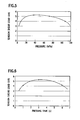
- sufficiently high tension shear load is obtained with a wide range of pressure applied to the bonded portion, from 15 MPa to 120 MPa. In particular, at pressure between 20 MPa and 80 MPa, very high tension shear load is obtained.
- pressure applied to the bonded portion is less than 15 MPa, bonding strength cannot be ensured due to a lack of applied pressure.
- pressure applied to the bonded portion exceeds 120 MPa, the materials are deformed greatly and local thicknesses of the sheets become too small.
- Duration of pressing the bonded portion is preferably between 1 to 7 seconds since sufficient tension shear load can be obtained by pressing for only 1 second as evident from FIG. 6. Considering the fact that the pressing time exceeding 7 seconds reduces a tension shear load, it is preferred that upper limit of the pressing duration be set to 7 seconds.
- the sheets can be heated in a short period of time as shown in FIG. 6, enabling a significant reduction of time required until generation of a eutectic liquid of aluminum and zinc. Furthermore, even if bonding time apart from heating time can be as short as 1 second, it is possible to produce a sufficiently high tension shear load because of the bonding mechanism of a eutectic liquid of aluminum, zinc and iron. Moreover, by increasing outputs from a power source that supplies high frequency currents to the first and second high frequency induction heating coils 6 and 7, time for heating the galvanized steel sheet 1 and the aluminum alloy sheet 3 can be reduced. Hence, with the bonding method of the present invention, cycle time as short as that of spot welding can be achieved.
- the base materials are heated by transferred heat from a heating source. Therefore, it takes about 3 minutes until the temperature of the sheets increases from room temperature to 500 °C.
- the use of the induction heating method as described in the embodiment enables the dissimilar metal sheets to be bonded together in an extremely short period of time while ensuring sufficient bonding strength as described earlier.
- the dissimilar metal sheets can be heated in a short period of time in comparison with heating by the direct heating method. Therefore, the bonding interface is prevented from being oxidized and inert gas is no longer necessary. Inert gas is not necessary because a eutectic liquid of the galvanized steel sheet 1 and the aluminum alloy sheet 3 is generated at interface temperature of about 400 °C, and the interface between the steel sheet and the aluminum alloy sheet becomes wet with the eutectic liquid, preventing oxidization of the interface. Hence, in this embodiment, bonding in the atmosphere is feasible without a need for anti-oxidant shielding gas. Because shielding gas spray nozzle is also no longer necessary, the structure of the liquid phase diffusion bonding apparatus can be simplified.
- dissimilar metal sheets can be bonded together at low pressure, which can prevent a reduction of strength and deformation of base materials due to reduced thicknesses. Since heating temperature is low, a reduction of strength of the base materials caused by a thermal effect can also be prevented.
- only the first mold 2 can be moved by the hydraulic cylinder 5.
- the second mold 4 can also be moved by a hydraulic cylinder similarly to the first mold 2.
Landscapes
- Engineering & Computer Science (AREA)
- Mechanical Engineering (AREA)
- Pressure Welding/Diffusion-Bonding (AREA)
- General Induction Heating (AREA)
Abstract
Description
Claims (3)
- A liquid phase diffusion bonding method for dissimilar metal sheets, comprising:allowing a galvanized steel sheet (1) and an aluminum alloy sheet (3) to come into close contact with each other and pressing both sheets (1, 3) by using a first mold (2) of a liquid phase diffusion bonding apparatus and a second mold (4) of the same; andheating the galvanized steel sheet (1) and the aluminum alloy sheet (3) at approximately the same heat-up rate and at approximately the same temperature to perform liquid phase diffusion bonding of the sheets (1, 3) by using induction heat generated by applying high frequency currents to a first high frequency induction heating coil (6) provided on the first mold (2) and a second high frequency induction heating coil (7) provided on the second mold (4), the first high frequency induction heating coil (6) and the second high frequency induction heating coil (7) being positioned to sandwich the galvanized steel sheet (1) and the aluminum alloy sheet (3) at predetermined distances (H1, H2) from the sheets (1, 3), respectively.
- A liquid phase diffusion bonding method according to claim 1,
wherein bonding pressure applied to the galvanized steel sheet (1) and the aluminum alloy sheet (3) is within a range from 15 MPa to 120 MPa, and
interface temperature at a bonded portion of the galvanized steel sheet (1) and the aluminum alloy sheet (3) is within a range from 370 to 550 °C. - A liquid phase diffusion bonding apparatus, comprising:a first mold (2);a second mold (4);a pressure-applying device (5) which enables at least any one of the first mold (2) and the second mold (4) to be moved and presses a galvanized steel sheet (1) and an aluminum alloy sheet (3), both fixed between the first mold (2) and the second mold (4);a first high frequency induction heating coil (6) which is provided on the first mold (2) at a position a predetermined distance (H1) away from the galvanized steel sheet (1) and applies a high frequency current to generate an induction current through the galvanized steel sheet (1) so that the galvanized steel sheet (1) is heated; anda second high frequency induction heating coil (7) which is provided on the second mold (4) at a position a predetermined distance (H2) away from the aluminum alloy sheet (3) and applies a high frequency current to generate an induction current through the aluminum alloy sheet (3) so that the aluminum alloy sheet (3) is heated.
Applications Claiming Priority (2)
| Application Number | Priority Date | Filing Date | Title |
|---|---|---|---|
| JP2004039897 | 2004-02-17 | ||
| JP2004039897A JP4181063B2 (en) | 2004-02-17 | 2004-02-17 | Liquid phase diffusion bonding method for dissimilar metal sheets |
Publications (2)
| Publication Number | Publication Date |
|---|---|
| EP1563941A1 true EP1563941A1 (en) | 2005-08-17 |
| EP1563941B1 EP1563941B1 (en) | 2008-03-12 |
Family
ID=34697984
Family Applications (1)
| Application Number | Title | Priority Date | Filing Date |
|---|---|---|---|
| EP05001904A Expired - Lifetime EP1563941B1 (en) | 2004-02-17 | 2005-01-31 | Liquid phase diffusion bonding method for dissimilar metal sheets and liquid phase diffusion bonding apparatus for the same |
Country Status (5)
| Country | Link |
|---|---|
| US (1) | US7119309B2 (en) |
| EP (1) | EP1563941B1 (en) |
| JP (1) | JP4181063B2 (en) |
| CN (1) | CN100346921C (en) |
| DE (1) | DE602005005228T2 (en) |
Cited By (1)
| Publication number | Priority date | Publication date | Assignee | Title |
|---|---|---|---|---|
| CN103878473A (en) * | 2014-03-12 | 2014-06-25 | 王子延 | Hot-extrusion welding device for metal liquid-solid state interface |
Families Citing this family (19)
| Publication number | Priority date | Publication date | Assignee | Title |
|---|---|---|---|---|
| JP4601052B2 (en) * | 2004-12-24 | 2010-12-22 | 日産自動車株式会社 | Dissimilar metal joining method |
| JP3927987B2 (en) * | 2005-11-21 | 2007-06-13 | 株式会社神戸製鋼所 | Dissimilar material joining method |
| JP4868210B2 (en) * | 2005-12-06 | 2012-02-01 | 日産自動車株式会社 | Bonding method of dissimilar materials |
| US20100212945A1 (en) * | 2006-08-31 | 2010-08-26 | Anthony Faraci | Bond head assembly and system |
| JP5376391B2 (en) * | 2007-03-30 | 2013-12-25 | 日産自動車株式会社 | Dissimilar metal joining method and joining structure |
| JP5263923B2 (en) * | 2007-11-29 | 2013-08-14 | 国立大学法人 新潟大学 | Diffusion bonding method and apparatus |
| CN102079011B (en) * | 2010-12-31 | 2013-06-19 | 南京理工大学 | Semi-solid deposition pressure welding device for dissimilar metals |
| CN102581414A (en) * | 2012-03-16 | 2012-07-18 | 李明雨 | Method for brazing copper aluminum tubes without aid of brazing flux |
| CN103521909A (en) * | 2013-10-31 | 2014-01-22 | 北京石油化工学院 | Liquid phase diffusion welder |
| JP6381944B2 (en) * | 2014-04-01 | 2018-08-29 | 東洋鋼鈑株式会社 | Method for producing metal laminate |
| CN104191085B (en) * | 2014-09-01 | 2016-03-30 | 山东大学 | A low-temperature diffusion bonding method of aluminum-steel-aluminum with quasicrystal interlayer added |
| CN107096987A (en) * | 2017-03-22 | 2017-08-29 | 华南理工大学 | A kind of quick diffusion welding method of metal bar based on pulsed current annealing |
| CN107378224A (en) * | 2017-09-13 | 2017-11-24 | 无锡海菲焊接设备有限公司 | Aluminium is flexible coupling welding machine and welding procedure |
| CN107695504A (en) * | 2017-09-25 | 2018-02-16 | 苏州铜盟电气有限公司 | Medium temperature forges and presses welding structure |
| JP7065478B2 (en) * | 2017-11-01 | 2022-05-12 | 株式会社小松精機工作所 | Metal sheet metal joining device |
| CN111229954A (en) * | 2019-11-20 | 2020-06-05 | 武汉科技大学 | A method for composite connection of steel and aluminum dissimilar metals of automobile body by induction rolling |
| TWI751607B (en) * | 2020-07-10 | 2022-01-01 | 復盛應用科技股份有限公司 | Forming mold heating method and forming mold |
| CN112548301B (en) * | 2020-11-03 | 2022-05-27 | 武汉科技大学 | Induction static pressure welding method for steel-aluminum dissimilar metal of automobile body |
| CN113501725B (en) * | 2021-07-21 | 2022-11-08 | 江苏富乐华半导体科技股份有限公司 | Preparation method of aluminum-coated ceramic insulating lining plate |
Citations (2)
| Publication number | Priority date | Publication date | Assignee | Title |
|---|---|---|---|---|
| US3436805A (en) * | 1965-08-09 | 1969-04-08 | North American Rockwell | Method of joining aluminum and ferrous members |
| US6389697B1 (en) * | 2000-07-17 | 2002-05-21 | Fuel Cell Components And Integrators, Inc. | Fabricating automotive spaceframes using electromagnetic forming or magnetic pulse welding |
Family Cites Families (6)
| Publication number | Priority date | Publication date | Assignee | Title |
|---|---|---|---|---|
| US2914641A (en) * | 1958-01-02 | 1959-11-24 | Union Carbide Corp | Welding dissimilar metal members |
| JPS55165291A (en) * | 1979-06-08 | 1980-12-23 | Toshiba Corp | Vacuum diffusion bonding method |
| JP3250582B2 (en) * | 1993-10-28 | 2002-01-28 | アイシン精機株式会社 | Bonding method of Ti-Al intermetallic compound |
| JP3757506B2 (en) * | 1996-12-24 | 2006-03-22 | 株式会社日立製作所 | Joining method of heat-resistant alloys |
| JP4253488B2 (en) | 2002-10-01 | 2009-04-15 | 高周波熱錬株式会社 | Solid state bonding apparatus and solid state bonding method for dissimilar metal thin plates |
| CN1240513C (en) * | 2003-04-28 | 2006-02-08 | 西安交通大学 | Phase change-diffusion brass solder technique |
-
2004
- 2004-02-17 JP JP2004039897A patent/JP4181063B2/en not_active Expired - Fee Related
-
2005
- 2005-01-31 EP EP05001904A patent/EP1563941B1/en not_active Expired - Lifetime
- 2005-01-31 DE DE602005005228T patent/DE602005005228T2/en not_active Expired - Lifetime
- 2005-02-10 US US11/054,547 patent/US7119309B2/en not_active Expired - Fee Related
- 2005-02-17 CN CNB2005100083537A patent/CN100346921C/en not_active Expired - Fee Related
Patent Citations (2)
| Publication number | Priority date | Publication date | Assignee | Title |
|---|---|---|---|---|
| US3436805A (en) * | 1965-08-09 | 1969-04-08 | North American Rockwell | Method of joining aluminum and ferrous members |
| US6389697B1 (en) * | 2000-07-17 | 2002-05-21 | Fuel Cell Components And Integrators, Inc. | Fabricating automotive spaceframes using electromagnetic forming or magnetic pulse welding |
Non-Patent Citations (1)
| Title |
|---|
| WATANABE T.: "Joining of an iron pipe to an aluminum pipe by plating", QUATERLY JOURNAL OF JAPAN WELDING SOCIETY, November 2000 (2000-11-01), XP002329688, Retrieved from the Internet <URL:http://md1.csa.com/partners/viewrecord.php?requester=gs&collection=TRD&recid=200104550718MD&recid=200104P50129AI> [retrieved on 20050527] * |
Cited By (1)
| Publication number | Priority date | Publication date | Assignee | Title |
|---|---|---|---|---|
| CN103878473A (en) * | 2014-03-12 | 2014-06-25 | 王子延 | Hot-extrusion welding device for metal liquid-solid state interface |
Also Published As
| Publication number | Publication date |
|---|---|
| DE602005005228D1 (en) | 2008-04-24 |
| JP4181063B2 (en) | 2008-11-12 |
| US7119309B2 (en) | 2006-10-10 |
| CN100346921C (en) | 2007-11-07 |
| JP2005230827A (en) | 2005-09-02 |
| US20050178819A1 (en) | 2005-08-18 |
| EP1563941B1 (en) | 2008-03-12 |
| DE602005005228T2 (en) | 2009-03-19 |
| CN1657217A (en) | 2005-08-24 |
Similar Documents
| Publication | Publication Date | Title |
|---|---|---|
| US7119309B2 (en) | Liquid phase diffusion bonding method for dissimilar metal sheets and liquid phase diffusion bonding apparatus for the same | |
| US9149888B2 (en) | Machine for joining the ends of steel strips which machine is suited to the induction heat treatment of joining welds | |
| CN103260809B (en) | The conjugant of conductive material | |
| KR20080010302A (en) | Joining method, joining structure and joining device of dissimilar metals | |
| US6002098A (en) | Laser-assisted plating of strip | |
| JP4253488B2 (en) | Solid state bonding apparatus and solid state bonding method for dissimilar metal thin plates | |
| KR20220152215A (en) | Solid state point joining method and solid state point joining device | |
| CN111886106A (en) | Solid-phase bonding method and solid-phase bonding apparatus for metal material | |
| JP2001105158A (en) | Induction heating coil for railroad rail diffusion bonding and railroad rail diffusion bonding method using the same | |
| CN108115300A (en) | The method for connecting component made of different materials | |
| CN107414283B (en) | An automatic wire-feeding friction stir welding method for butt joint of dissimilar metal materials | |
| JP4962752B2 (en) | Method of joining dissimilar metals with high energy beam | |
| JP5686582B2 (en) | Axle case manufacturing method | |
| JP4470721B2 (en) | Welding method and welding shaping apparatus | |
| KR20140016268A (en) | Method of producing a welded article of dispersion strengthened platinum based alloy with two steps welding | |
| JP3079995B2 (en) | Diffusion bonding method of metal material | |
| JP2006159240A (en) | High energy density beam welded product, high energy density beam welding method, welding method, welding auxiliary device | |
| JP7853635B1 (en) | Spot welded joints | |
| KR101192426B1 (en) | device for adhering of aluminum tube products | |
| JP3447891B2 (en) | How to join the end of the strip to a flat surface | |
| JP2007260701A (en) | Dissimilar material joining method | |
| CN112548301B (en) | Induction static pressure welding method for steel-aluminum dissimilar metal of automobile body | |
| JP2006116600A (en) | Dissimilar material joining method | |
| JP2009082934A (en) | Dissimilar materials joining method | |
| JP2010131631A (en) | Joining method of member and joined body |
Legal Events
| Date | Code | Title | Description |
|---|---|---|---|
| PUAI | Public reference made under article 153(3) epc to a published international application that has entered the european phase |
Free format text: ORIGINAL CODE: 0009012 |
|
| 17P | Request for examination filed |
Effective date: 20050131 |
|
| AK | Designated contracting states |
Kind code of ref document: A1 Designated state(s): AT BE BG CH CY CZ DE DK EE ES FI FR GB GR HU IE IS IT LI LT LU MC NL PL PT RO SE SI SK TR |
|
| AX | Request for extension of the european patent |
Extension state: AL BA HR LV MK YU |
|
| AKX | Designation fees paid |
Designated state(s): DE FR GB |
|
| GRAP | Despatch of communication of intention to grant a patent |
Free format text: ORIGINAL CODE: EPIDOSNIGR1 |
|
| GRAS | Grant fee paid |
Free format text: ORIGINAL CODE: EPIDOSNIGR3 |
|
| GRAA | (expected) grant |
Free format text: ORIGINAL CODE: 0009210 |
|
| AK | Designated contracting states |
Kind code of ref document: B1 Designated state(s): DE FR GB |
|
| REG | Reference to a national code |
Ref country code: GB Ref legal event code: FG4D |
|
| REF | Corresponds to: |
Ref document number: 602005005228 Country of ref document: DE Date of ref document: 20080424 Kind code of ref document: P |
|
| ET | Fr: translation filed | ||
| PLBE | No opposition filed within time limit |
Free format text: ORIGINAL CODE: 0009261 |
|
| STAA | Information on the status of an ep patent application or granted ep patent |
Free format text: STATUS: NO OPPOSITION FILED WITHIN TIME LIMIT |
|
| 26N | No opposition filed |
Effective date: 20081215 |
|
| REG | Reference to a national code |
Ref country code: FR Ref legal event code: PLFP Year of fee payment: 11 |
|
| PGFP | Annual fee paid to national office [announced via postgrant information from national office to epo] |
Ref country code: DE Payment date: 20150127 Year of fee payment: 11 |
|
| PGFP | Annual fee paid to national office [announced via postgrant information from national office to epo] |
Ref country code: FR Payment date: 20150108 Year of fee payment: 11 Ref country code: GB Payment date: 20150128 Year of fee payment: 11 |
|
| REG | Reference to a national code |
Ref country code: DE Ref legal event code: R119 Ref document number: 602005005228 Country of ref document: DE |
|
| GBPC | Gb: european patent ceased through non-payment of renewal fee |
Effective date: 20160131 |
|
| REG | Reference to a national code |
Ref country code: FR Ref legal event code: ST Effective date: 20160930 |
|
| PG25 | Lapsed in a contracting state [announced via postgrant information from national office to epo] |
Ref country code: DE Free format text: LAPSE BECAUSE OF NON-PAYMENT OF DUE FEES Effective date: 20160802 Ref country code: GB Free format text: LAPSE BECAUSE OF NON-PAYMENT OF DUE FEES Effective date: 20160131 |
|
| PG25 | Lapsed in a contracting state [announced via postgrant information from national office to epo] |
Ref country code: FR Free format text: LAPSE BECAUSE OF NON-PAYMENT OF DUE FEES Effective date: 20160201 |