EP1562807B1 - Vehicle dynamic control with image sensor system - Google Patents
Vehicle dynamic control with image sensor system Download PDFInfo
- Publication number
- EP1562807B1 EP1562807B1 EP03767403A EP03767403A EP1562807B1 EP 1562807 B1 EP1562807 B1 EP 1562807B1 EP 03767403 A EP03767403 A EP 03767403A EP 03767403 A EP03767403 A EP 03767403A EP 1562807 B1 EP1562807 B1 EP 1562807B1
- Authority
- EP
- European Patent Office
- Prior art keywords
- motor vehicle
- image
- measured value
- vehicle
- sensor system
- Prior art date
- Legal status (The legal status is an assumption and is not a legal conclusion. Google has not performed a legal analysis and makes no representation as to the accuracy of the status listed.)
- Expired - Lifetime
Links
- 238000000034 method Methods 0.000 claims abstract description 37
- 230000033001 locomotion Effects 0.000 claims description 60
- 239000013598 vector Substances 0.000 claims description 60
- 230000001133 acceleration Effects 0.000 claims description 38
- 230000008569 process Effects 0.000 claims description 5
- 238000004590 computer program Methods 0.000 claims description 3
- 238000013519 translation Methods 0.000 claims description 3
- 230000008859 change Effects 0.000 description 26
- 238000012545 processing Methods 0.000 description 17
- 238000001514 detection method Methods 0.000 description 8
- 238000005070 sampling Methods 0.000 description 5
- 238000009434 installation Methods 0.000 description 4
- 230000008901 benefit Effects 0.000 description 3
- 230000005540 biological transmission Effects 0.000 description 3
- 238000004364 calculation method Methods 0.000 description 3
- 238000005259 measurement Methods 0.000 description 3
- 238000012544 monitoring process Methods 0.000 description 3
- 230000005855 radiation Effects 0.000 description 3
- 238000012935 Averaging Methods 0.000 description 2
- 230000001419 dependent effect Effects 0.000 description 2
- 238000010586 diagram Methods 0.000 description 2
- 230000005684 electric field Effects 0.000 description 2
- 230000005670 electromagnetic radiation Effects 0.000 description 2
- 238000005516 engineering process Methods 0.000 description 2
- 230000005484 gravity Effects 0.000 description 2
- 230000006872 improvement Effects 0.000 description 2
- 230000009467 reduction Effects 0.000 description 2
- 230000006978 adaptation Effects 0.000 description 1
- 230000003044 adaptive effect Effects 0.000 description 1
- 230000033228 biological regulation Effects 0.000 description 1
- 238000004891 communication Methods 0.000 description 1
- 239000000446 fuel Substances 0.000 description 1
- 238000003709 image segmentation Methods 0.000 description 1
- 238000002347 injection Methods 0.000 description 1
- 239000007924 injection Substances 0.000 description 1
- 238000012423 maintenance Methods 0.000 description 1
- 230000010287 polarization Effects 0.000 description 1
- 238000007781 pre-processing Methods 0.000 description 1
- 230000004044 response Effects 0.000 description 1
- 238000000926 separation method Methods 0.000 description 1
- 238000001228 spectrum Methods 0.000 description 1
- 230000006641 stabilisation Effects 0.000 description 1
- 238000011105 stabilization Methods 0.000 description 1
- XLYOFNOQVPJJNP-UHFFFAOYSA-N water Substances O XLYOFNOQVPJJNP-UHFFFAOYSA-N 0.000 description 1
Images
Classifications
-
- B—PERFORMING OPERATIONS; TRANSPORTING
- B60—VEHICLES IN GENERAL
- B60T—VEHICLE BRAKE CONTROL SYSTEMS OR PARTS THEREOF; BRAKE CONTROL SYSTEMS OR PARTS THEREOF, IN GENERAL; ARRANGEMENT OF BRAKING ELEMENTS ON VEHICLES IN GENERAL; PORTABLE DEVICES FOR PREVENTING UNWANTED MOVEMENT OF VEHICLES; VEHICLE MODIFICATIONS TO FACILITATE COOLING OF BRAKES
- B60T8/00—Arrangements for adjusting wheel-braking force to meet varying vehicular or ground-surface conditions, e.g. limiting or varying distribution of braking force
- B60T8/17—Using electrical or electronic regulation means to control braking
- B60T8/1755—Brake regulation specially adapted to control the stability of the vehicle, e.g. taking into account yaw rate or transverse acceleration in a curve
- B60T8/17551—Brake regulation specially adapted to control the stability of the vehicle, e.g. taking into account yaw rate or transverse acceleration in a curve determining control parameters related to vehicle stability used in the regulation, e.g. by calculations involving measured or detected parameters
-
- B—PERFORMING OPERATIONS; TRANSPORTING
- B60—VEHICLES IN GENERAL
- B60T—VEHICLE BRAKE CONTROL SYSTEMS OR PARTS THEREOF; BRAKE CONTROL SYSTEMS OR PARTS THEREOF, IN GENERAL; ARRANGEMENT OF BRAKING ELEMENTS ON VEHICLES IN GENERAL; PORTABLE DEVICES FOR PREVENTING UNWANTED MOVEMENT OF VEHICLES; VEHICLE MODIFICATIONS TO FACILITATE COOLING OF BRAKES
- B60T8/00—Arrangements for adjusting wheel-braking force to meet varying vehicular or ground-surface conditions, e.g. limiting or varying distribution of braking force
- B60T8/17—Using electrical or electronic regulation means to control braking
- B60T8/172—Determining control parameters used in the regulation, e.g. by calculations involving measured or detected parameters
-
- G—PHYSICS
- G01—MEASURING; TESTING
- G01S—RADIO DIRECTION-FINDING; RADIO NAVIGATION; DETERMINING DISTANCE OR VELOCITY BY USE OF RADIO WAVES; LOCATING OR PRESENCE-DETECTING BY USE OF THE REFLECTION OR RERADIATION OF RADIO WAVES; ANALOGOUS ARRANGEMENTS USING OTHER WAVES
- G01S5/00—Position-fixing by co-ordinating two or more direction or position line determinations; Position-fixing by co-ordinating two or more distance determinations
- G01S5/16—Position-fixing by co-ordinating two or more direction or position line determinations; Position-fixing by co-ordinating two or more distance determinations using electromagnetic waves other than radio waves
-
- G—PHYSICS
- G06—COMPUTING; CALCULATING OR COUNTING
- G06T—IMAGE DATA PROCESSING OR GENERATION, IN GENERAL
- G06T7/00—Image analysis
- G06T7/70—Determining position or orientation of objects or cameras
- G06T7/73—Determining position or orientation of objects or cameras using feature-based methods
-
- G—PHYSICS
- G06—COMPUTING; CALCULATING OR COUNTING
- G06T—IMAGE DATA PROCESSING OR GENERATION, IN GENERAL
- G06T2207/00—Indexing scheme for image analysis or image enhancement
- G06T2207/10—Image acquisition modality
- G06T2207/10004—Still image; Photographic image
- G06T2207/10012—Stereo images
-
- G—PHYSICS
- G06—COMPUTING; CALCULATING OR COUNTING
- G06T—IMAGE DATA PROCESSING OR GENERATION, IN GENERAL
- G06T2207/00—Indexing scheme for image analysis or image enhancement
- G06T2207/30—Subject of image; Context of image processing
- G06T2207/30244—Camera pose
Definitions
- the invention relates to a method and a device for driving dynamics control in a motor vehicle having at least one image sensor system, comprising at least two image sensors which record substantially the same scene.
- the difference between the desired behavior and the actual behavior is determined as a system deviation and the individual actuators, for example the wheel brakes, are controlled with the aim of minimizing the system deviation.
- the individual actuators for example the wheel brakes
- yaw rate sensors, lateral acceleration sensors, steering wheel angle sensors, admission pressure sensors and speed sensors are used as sensors.
- References to the use of at least one image sensor system consisting of at least two image sensors which record essentially the same scene are missing here.
- the European patent application EP 1 089 231 A2 discloses an apparatus for detecting road markings on the road surface based on stereo image pairs of a stereo camera. From the European patent application EP 0 896 267 A2 a system for detecting the position of a motor vehicle is known, the system comprising a stereo camera.
- the method described below and the device for vehicle dynamics control in a motor vehicle with at least one image sensor system, wherein at least two image sensors are provided which receive substantially the same scene, have the advantage that image sensor systems are provided in motor vehicles for use in other functions.
- Particularly advantageous are stereo cameras.
- Image sensor systems and stereo cameras can be used, for example, as part of an automatic cruise control and / or distance control, for example in the Adaptive Cruise Control (ACC) system, in a motor vehicle.
- ACC Adaptive Cruise Control
- Further applications of outdoor video camera systems are e.g. be: Precrashsensenstechnik, pedestrian detection, rollover detection.
- Using the same multi-function image sensor system reduces the cost of such systems by reducing the cost per function.
- connection of the image sensor system and / or the stereo camera to a sensor platform in which various sensors are connected to a data bus and are used synergistically by various control devices.
- This leads to a further reduction in the cost per function.
- This allows a wide distribution of the functions described in motor vehicles. Especially a wide spread of vehicle dynamics control in motor vehicles, which are located in the traffic area, leads to an overall increase in traffic safety.
- At least one measured value is determined from the generated image information, the measured value being used for vehicle dynamics control.
- the alternative or additional determination of further motion vectors in the three main axes of the motor vehicle and / or of further rotational vectors about them is particularly advantageous.
- the determination of the roll acceleration and / or the roll speed and / or the roll angle advantageously makes it possible to detect and avoid lateral roll over of the motor vehicle.
- this function advantageously leads to an increase in traffic safety.
- the pitch acceleration and / or the pitching speed and / or the pitch angle dangers resulting from an excessive pitching motion of the motor vehicle are detected.
- a tilting of the motor vehicle on the rear axle by suitable control of actuators, for example, of individual wheel brakes prevented.
- actuators for example, of individual wheel brakes prevented.
- this function leads to an increase in traffic safety.
- the determination of all three motion vectors in the three main axes of the motor vehicle and of the associated rotation vectors about the same. This allows the three-dimensional recognition of the vehicle movement.
- the determination of the yaw rate and / or the yaw angle and / or the lateral acceleration of the motor vehicle from the generated image information allows the use of the image sensor system as a yaw rate sensor and / or as a lateral acceleration sensor for vehicle dynamics control. This leads advantageously to a cost reduction, because the image sensor system alternatively or simultaneously takes over the function of the yaw rate sensor or the lateral acceleration sensor. By the various uses of the image sensor system for multiple functions, the cost per puncture are advantageously reduced.
- the image sensor system enables a reliable and rapid determination of the yaw rate and / or the yaw angle and / or the lateral acceleration of the motor vehicle.
- the determination of the three-dimensional rotational movement and / or the three-dimensional translational movement of the motor vehicle in dependence on image information of at least one image sensor system, in particular a stereo camera, as a result the dynamics of the motor vehicle ground contact independent determinable. Furthermore, it is advantageous that in addition to at least one image sensor system in and / or opposite to the direction of travel, at least one second image sensor system is arranged transversely to the direction of travel, since this contributes to an improved three-dimensional determination of the movement of the motor vehicle.
- At least one stationary pixel is determined.
- the determination of a measured value for driving dynamics control and / or the determination of the three-dimensional rotational movement and / or the three-dimensional translational movement as a function of the determined at least one stationary pixel leads to a further improvement of the proposed methods and the corresponding devices.
- the use of more than one image sensor system having at least two image sensors that record substantially the same scene the determination of the differences of the two position vectors for the same pixel and the change of the calculation of the spatial translational and rotational motion vectors of the vehicle.
- the measured values are determined independently by at least two image sensor systems.
- a computer program with program code means to perform all the steps of the method described below when the program is run on a computer.
- the use of a computer program enables the process to be adapted quickly and inexpensively, for example by adapting parameters to the respective vehicle type and / or components of the vehicle dynamics control.
- the maintenance is improved in an advantageous manner, since the individual process steps are not implemented in hardware, but in software.
- a sensor unit with at least one image sensor system is advantageous, wherein means are provided for determining at least one rotation vector and / or at least one translation motion vector.
- the sensor unit can be used advantageously outside the automotive technology.
- the field of application of the sensor unit extends to application areas where at least one rotation vector and / or at least one motion vector of a moving and / or accelerated object is required.
- the required vectors are obtained from the image information of the environment.
- this sensor unit is suitable for appropriate installation in a motor vehicle in an advantageous manner for determining the yaw rate and / or the yaw angle and / or the lateral acceleration of the motor vehicle.
- This sensor unit can thus be used as a sensor of the method described below and the device for driving dynamics control described below.
- FIG. 1 shows a block diagram of the vehicle dynamics control in a motor vehicle 10 in the preferred embodiment, consisting of sensors 12, actuators (actuators) 14, the driver (desired behavior) 16, the vehicle behavior (actual behavior) 18, the deviation 20 and the vehicle dynamics controller 22.
- the vehicle dynamics control has Aim to keep the motor vehicle 10 stable and on track.
- sensors 12, which are located in the motor vehicle 10 the driver's request 16 is determined.
- the vehicle behavior 18 is determined by sensors 12. From the driver's request 16 and the vehicle behavior 18, the control deviation 20 is calculated.
- the control deviation 20 serves as an input variable for the vehicle dynamics controller 22.
- the vehicle dynamics controller 22 controls the actuators (actuators) 14 with the aim of minimizing the system deviation 20.
- actuators 14 in particular the wheel brakes and / or the engine of the motor vehicle 10 are used.
- the motor vehicle 10 is individually steerable and the desired driving behavior is achieved even in critical driving situations.
- the vehicle dynamics control thus reduces the risk of a collision, the risk of a rollover and / or the risk that the motor vehicle 10 comes off the road.
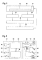
- FIG. 2 shows an overview drawing of the vehicle dynamics control in a motor vehicle in the preferred embodiment, consisting of sensors 12, a processing unit / control unit 34 and actuators 14.
- sensors 12 a stereo camera 50, a steering wheel angle sensor 28, a form pressure sensor 30 and speed sensors 32 are used.
- the stereo camera 50 is used to determine yaw rate, yaw rate, and lateral acceleration.
- the yaw rate of the motor vehicle is understood to mean the rotational speed of the motor vehicle by a rotational movement of the motor vehicle about its vertical axis, while the transverse acceleration of a motor vehicle is the acceleration perpendicular to Driving direction and parallel to the road describes.
- the yaw angle is the angle of rotation of the motor vehicle about its vertical axis with respect to a position of the motor vehicle which is past in time.
- the yaw angle is determined in the preferred embodiment from the yaw rate as the accumulated yaw angle.
- the steering wheel angle sensor 28 detects the steering wheel angle of the motor vehicle.
- the form pressure sensor 30 is arranged in the brake system and serves to detect the actuation of the brake by the driver.
- Four speed sensors 32 are each connected to a wheel of the motor vehicle and are used to determine the rotational speed of the wheels of the motor vehicle.
- the processing unit / control unit 34 processes the information from the sensors 12. It has an internal controller hierarchy. A distinction is made between the superimposed driving dynamics controller 22 and the subordinate controllers 36.
- a subordinate controller 36 differentiates one in the preferred embodiment between the brake slip controller, the traction controller and the engine drag torque controller.
- the friction coefficients and the vehicle speed are included in the calculation of the driver's request.
- These additionally calculated parameters are estimated from the signals of the rotational speed sensors 32, the stereo camera 50 and the pre-pressure sensors 30.
- the vehicle behavior is determined from the signals of the stereo camera 50 and an estimated in the processing unit / control unit 34 from the sensor signals slip angle of the motor vehicle.
- the driving dynamics controller 22 controls the two state variables yaw rate and slip angle of the motor vehicle.
- As actuators 14, the wheel brakes 40 are used, which are controlled by the hydraulic unit 38.
- a stereo camera 50 which consists of two image sensors which image the same scene but at a slightly different viewing angle.
- image sensors CCD image sensors and / or CMOS image sensors are used.
- the stereo camera 50 transmits image information of the vehicle environment to the processing unit / control unit 34.
- the image information of the stereo camera 50 is electrically and / or optically transmitted to the processing unit / control unit 34 via a signal line. Alternatively or additionally, a transmission of the image information by radio is possible.
- the stereo camera 50 has in the preferred embodiment, a range of about 4 meters to 40 meters, a vertical opening angle of about 17 degrees and a Sample rate of 10 milliseconds.
- the processing unit / control unit 34 consists of several in FIG. 5 illustrated modules which are configured in the preferred embodiment as programs of at least one microprocessor.
- FIG. 3 shows a drawing of the arrangement of the components of the vehicle dynamics control in a motor vehicle 10 in the preferred embodiment.
- the sensors 28, 30, 32, 48, 50, the actuators 38, 42 and the processing unit / control unit 34 are connected in the preferred embodiment via a CAN bus 54.
- the CAN bus 54 is a communication data bus.
- sensors the steering wheel angle sensor 28, the form pressure sensor 30, the four rotation speed sensors 32, and the stereo camera 50 are used.
- the control unit of the engine management 42 with the throttle valve 48 and the hydraulic unit 38 are located.
- the hydraulic unit 38 is connected via hydraulic lines 56 with four wheel brakes 40, and the brake booster with master cylinder 52.
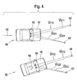
- FIG. 4 shows a motor vehicle 10 with a stereo camera 50 in the preferred embodiment in a first viewing time 90 and a second viewing time 92.
- the stereo camera 50 is mounted in the motor vehicle 10 in the region of the rearview mirror behind the windshield.
- the viewing direction of the stereo camera 50 is in the direction of travel 58 of the motor vehicle 10.
- the stereo camera 50 determines image information of the automotive environment.
- a first stationary pixel 60 and a second fixed pixel 62 is located.
- Stationary pixels are, for example, lane markings and / or traffic signs and / or piles and / or trees and / or edge posts and / or houses.
- the vectors V are respectively drawn from the image sensor objective center of the two image sensors of the stereo camera 50 to the two stationary pixels 60, 62.
- the first index of the vector V denotes the image sensors, while the second index indicates the pixels 60, 62.
- the third index indicates the time of the vector.
- V 212 denotes the vector V from the second image sensor to the first stationary pixel 60 at the second observation time 92.
- Vectors V 111 , V 121 , V 112 , V 122 , V 211 , V 221 , V 212, and V 222 are drawn .
- the X components of the vectors change during a yaw motion 94 of the motor vehicle 10 from a first viewing time 90 at a second time 92.
- the processing unit / control unit computes the vectors for the driving stability detection synchronously from the image information of the two image sensors of the stereo camera 50 into a plurality of pixels 60, 62 and / or a cluster of pixels.
- the vectorial change between the individual images is considered. For example, a cluster of pixels uses a hundred pixels. The use of a larger and / or smaller number is alternatively possible.
- the processing unit / control unit derives the rotation information about the Z axis and / or the lateral acceleration of the motor vehicle from the individual image vectors and calculates the yaw rate and / or the accumulated yaw angle and / or the lateral acceleration therefrom.
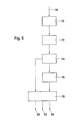
- FIG. 5 shows a flowchart of the method for driving dynamics control in a motor vehicle in the preferred embodiment.
- the yaw rate 80 and / or the yaw angle 82 and / or the lateral acceleration 84 is determined.
- the image information 68 is sent to the module 70 for preprocessing.
- the module 70 is used in particular for improving the image quality and / or for eliminating interference.
- a distinction from moving pixels is possible in that the component of the change in distance in the vehicle longitudinal direction to these moving pixels changes in first approximation at a speed other than the intrinsic speed of the motor vehicle.
- movements of pixels perpendicular to the direction of travel of the motor vehicle for example, a cruising other motor vehicle, further criteria are needed.
- the wheel revolutions of the cruising motor vehicle used as a non-consideration criterion and thus reliably detects moving pixels.
- a stationary pixel is each pixel in which the image coordinates of the pixel only change between two measurement cycles, as estimated from the vehicle speed and the curve radius of the motor vehicle.
- the determination of stationary pixels in the module 72 is based on known methods of image processing, in particular image segmentation, feature determination and object recognition. In the stereo camera, the image coordinates can be determined in particular by the method of triangulation.
- the module 74 is used to determine image coordinates of the specific stationary pixels. For a single pixel, the image coordinates are determined directly, while for a cluster of pixels, a centroid of the cluster is determined and used to determine the image coordinates. A fixed pixel is thus defined either by a single dot (pixel) or a cluster of pixels.
- the image coordinates of the particular fixed pixels are either stored in module 76 and / or forwarded to module 78 for determining the output values.
- the image vector changes and, therefrom, the output yaw rate 80 and / or yaw rate 82 and / or lateral acceleration 84 are determined in module 78.
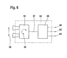
- FIG. 6 shows a sensor unit 64 consisting of an image sensor system 50 and a processing means 66.
- the image sensor system consists of two image sensors which record substantially the same scene. Alternatively, the use of a stereo camera is possible. For example, CCD image sensors and / or CMOS image sensors can be used as image sensors.
- the signal line 67 the image information is transmitted from the image sensor system 50 to the processing means 66. The transmission takes place electrically and / or optically. Alternatively or additionally, a transmission by radio is possible. In this embodiment, according to the described method in FIG.
- the yaw movement 86 and / or the transverse movement 88 is determined and provided as output values yaw rate 80 and / or yaw angle 82 and / or lateral acceleration 84 of the sensor unit 64.
- the processing means 66 consists of several in FIG. 5 illustrated modules, in this embodiment as programs of at least one microprocessor are designed.
- the image sensor system 50 and the processing means 66 form a unit.
- separation of the components of the image sensor system 50 and processing means 66 is possible.
- further means for determining at least one further rotation vector and / or at least one further movement vector are provided.
- a redundancy and / or a plausibility function is made possible.
- the field of application of the described sensor unit 64 is not limited to the automotive technology. Rather, the sensor unit 64 allows the determination of at least one rotation vector and / or the determination of at least one motion vector in general with respect to the sensor unit.
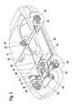
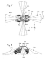
- FIG. 7 shows a motor vehicle 10 of another embodiment in a plan view, consisting of a first stereo camera 50a, a second stereo camera 50b, a third stereo camera 50c and a fourth stereo camera 50d.
- the first stereo camera 50a is mounted in the motor vehicle 10 in the region of the rearview mirror behind the windshield.
- the viewing direction 51a of the first stereo camera 50a is in the direction of travel 58 of the motor vehicle 10.
- the third stereo camera 50c is mounted on the tailgate of the motor vehicle 10 in the area of the license plate.
- the viewing direction 51c of the third stereo camera 50c is opposite to the direction of travel 58 of the motor vehicle 10.
- the second and fourth stereo camera 50b, 50d are arranged in the region of the B-pillar of the motor vehicle 10 such that their viewing directions 51b, 51d transversely to the direction of travel of the motor vehicle left or . on the right side there is. Furthermore, the shows FIG. 7 the vehicle-fixed Cartesian coordinate system with the axes x, y, z, whose zero points each lie in the camera lens centers.
- the dynamics (movement), that is to say in particular the three-dimensional translation and / or the three-dimensional rotation vectors, of the motor vehicle 10 are also measured independently of the ground contact, depending on the image information of the stereo cameras 50a, 50b, 50c, 50d.
- At least one stereo camera which is in the vehicle longitudinal direction and / or in the vehicle transverse direction, is required.
- a total of four stereo cameras 50a, 50b, 50c, 50d are used, which allow a redundant determination of the movement of the motor vehicle.
- the stereo cameras 50a, 50b, 50c, 50d in addition to determining the movement of the motor vehicle to provide or support other functions in the Related to the possibility of generating a complete all-round visibility used, such as pre-crash front detection and / or precrash-side detection and / or pre-crash rear impact detection and / or theft detection and / or vandalism detection when the motor vehicle 10 is turned off.
- the vehicle longitudinal speed component of the motor vehicle 10 is provided in this embodiment via the CAN bus or via a fast sensor bus. Furthermore, the transverse velocity component which is formed by the integral of a low-g lateral acceleration sensor, as used for vehicle dynamics control, is used as the measured value.
- stationary pixels are detected and distinguished from moving pixels in front of and laterally of the motor vehicle 10, since the latter change their distance from the camera at a speed which does not correspond to the available vehicle longitudinal velocity component or laterally to the vehicle lateral velocity component.
- stationary pixels are used in this embodiment, preferably stationary pixels on the road surface. Subsequently, the determination of the three-dimensional rotational movement and the three-dimensional translational movement of the motor vehicle 10 in addition to the already explained method after FIG. 4 described.
- FIG. 8 shows the motor vehicle 10 after FIG. 7 the further embodiment in side view.
- the fourth stereo camera 50d with the viewing direction 51d laterally to the motor vehicle 10, ie transversely to the direction of travel of the motor vehicle 10, located ,
- the described methods and the devices for driving dynamics control and / or for determining the movement of a motor vehicle are not limited to a single stereo camera, which is aligned in the direction of travel of the motor vehicle. Rather, the use of at least one image sensor system is possible, wherein at least two image sensors are provided, which receive substantially the same scene. With more than two image sensors, the accuracy of the process is increased.
- alternative installation options are conceivable. For example, the installation opposite to the direction of travel and / or to the side is possible.
- the device and the sensor unit are in addition to the CCD image sensors and / or the CMOS image sensors alternatively or additionally uses other image sensors that generate image information, such as line sensors.
- Image information is information contained in electromagnetic radiation in the ultraviolet radiation range, in the infrared radiation range and / or in the visible radiation range of the electromagnetic radiation spectrum.
- the intensity and / or the wavelength and / or the frequency and / or the polarization are used as image information.
- At least one rotation vector and / or at least one motion vector of the motor vehicle is determined from the generated image information.
- a rotation vector is a rotation vector of the motor vehicle about an arbitrary axis, rotation vectors preferably being determined in a main axis of the motor vehicle.
- the main axes of the motor vehicle are the vertical axis, the transverse axis and the longitudinal axis.
- a motion vector of the motor vehicle is a vector of the movement of the center of gravity of the motor vehicle in any direction.
- motion vectors are determined in a main axis of the motor vehicle.
- the term "nick" denotes a rotation vector about the transverse axis of the motor vehicle, ie perpendicular to the vertical axis and to the longitudinal axis.
- the pitch acceleration is the rotational acceleration of the motor vehicle in the direction of the transverse axis of the motor vehicle.
- Wank denotes a rotation vector about the longitudinal axis of the motor vehicle.
- the roll acceleration is the rotational acceleration of the motor vehicle in the direction of the longitudinal axis of the motor vehicle.
- vertical denotes a motion vector in the direction of the vertical axis of the motor vehicle, while the terms “longitudinal” and “transverse” describe a motion vector in the direction of the longitudinal axis and the transverse axis.
- all three described motion vectors in the three main axes of the motor vehicle with the associated rotation vectors to the same determined. The vehicle movement is detected and modeled three-dimensionally.
- At least two image sensor systems with at least two image sensors are used, which record essentially the same scene, in particular at least two stereo cameras.
- This enables a redundancy function and / or a plausibility function of the method described above.
- At least one rotation vector and / or at least one motion vector is determined independently of both image sensor systems by means of the redundancy function, and the measured value is determined by averaging.
- Plausibility function allows checking the measured values of the two image sensor systems by comparing the measured values.
- At least one yaw rate sensor and / or at least one lateral acceleration sensor for driving dynamics control are used as sensors in addition to the at least one image sensor system.
- the image sensor system is used for plausibility checking.
- the measured values of the yaw rate sensor and / or the lateral acceleration sensor are compared with the at least one measured value determined by the image sensor system.
- the image sensor system is used for the redundant determination of at least one measured value. This is done by averaging the at least one measured value of the image sensor system with at least one measured value of the yaw rate sensor and / or at least one measured value of the lateral acceleration sensor.
- Yaw rate sensors are sensors for measuring the yaw rate of a motor vehicle.
- Transverse acceleration sensors are inertial sensors for determining the lateral acceleration of a motor vehicle.
- a further variant of the method described above envisages that in order to save power, the at least one image sensor system is put into stand-by mode in defined operating situations, such as parked vehicle, and in response to at least one signal from another sensor monitoring the immediate vehicle environment. is set in operational readiness, that is "woken up".
- sensors for monitoring the vehicle environment acceleration sensors and / or electric field sensors are used. With the electric field sensors can by one or more in the immediate Sensors close to the sensor caused changes in the dielectric loss resistances at a suitable measuring frequency, eg 500 kHz, which change by> 20% because persons> 60% contain water.
- a suitable measuring frequency eg 500 kHz, which change by> 20% because persons> 60% contain water.
- the proximity of unwanted living beings, ie persons can be detected.
- the identity of desired persons, such as the vehicle owner is recognized as in the keyless entry system (Keyless Entry System) by the transponders contained in their ignition keys, the image sensor systems then remain inactive, since a monitoring of the vehicle environment is not necessary.
Abstract
Description
Die Erfindung betrifft ein Verfahren und eine Vorrichtung zur Fahrdynamikregelung in einem Kraftfahrzeug mit wenigstens einem Bildsensorsystem, bestehend aus wenigstens zwei Bildsensoren, die im wesentlichen dieselbe Szene aufnehmen.The invention relates to a method and a device for driving dynamics control in a motor vehicle having at least one image sensor system, comprising at least two image sensors which record substantially the same scene.
Vorrichtungen und Verfahren zur Fahrdynamikregelung in einem Kraftfahrzeug sind bekannt. Beispielsweise ist in Zanten, Erhardt, Pfaff: "
Aus der japanischen Offenlegungsschrift
Das nachfolgend beschriebene Verfahren und die Vorrichtung zur Fahrdynamikregelung in einem Kraftfahrzeug mit wenigstens einem Bildsensorsystem, wobei wenigstens zwei Bildsensoren vorgesehen sind, die im wesentlichen dieselbe Szene aufnehmen, haben den Vorteil, dass Bildsensorsysteme in Kraftfahrzeugen für den Einsatz in weitere Funktionen vorgesehen sind. Besonders vorteilhaft sind Stereokameras. Bildsensorsysteme und Stereokameras können beispielsweise als Bestandteil einer automatischen Geschwindigkeitsregelung und/oder Abstandsregelung, beispielsweise im System des Adaptive Cruise Control (ACC), in einem Kraftfahrzeug eingesetzt werden. Weitere Anwendungsmöglichkeiten von Außen-Videokamera-Systemen werden z.B. sein: Precrashsensensierung, Fußgängererkennung, Überrollerkennung. Die Verwendung desselben Bildsensorsystems für mehrere Funktionen führt zu einer Reduzierung der Kosten für solche Systeme, weil die Kosten pro Funktion gesenkt werden. Besonders vorteilhaft ist der Anschluss des Bildsensorsystems und/oder der Stereokamera an eine Sensorplattform, bei der verschiedene Sensoren an einem Datenbus angeschlossen sind und von verschiedenen Steuergeräten synergetisch genutzt werden. Dies führt zu einer weiteren Senkung der Kosten pro Funktion. Damit wird eine weite Verbreitung der beschriebenen Funktionen in Kraftfahrzeugen ermöglicht. Speziell eine weite Verbreitung der Fahrdynamikregelung in Kraftfahrzeugen, die sich im Verkehrsraum befinden, führt insgesamt zu einer Erhöhung der Verkehrssicherheit.The method described below and the device for vehicle dynamics control in a motor vehicle with at least one image sensor system, wherein at least two image sensors are provided which receive substantially the same scene, have the advantage that image sensor systems are provided in motor vehicles for use in other functions. Particularly advantageous are stereo cameras. Image sensor systems and stereo cameras can be used, for example, as part of an automatic cruise control and / or distance control, for example in the Adaptive Cruise Control (ACC) system, in a motor vehicle. Further applications of outdoor video camera systems are e.g. be: Precrashsensensierung, pedestrian detection, rollover detection. Using the same multi-function image sensor system reduces the cost of such systems by reducing the cost per function. Particularly advantageous is the connection of the image sensor system and / or the stereo camera to a sensor platform, in which various sensors are connected to a data bus and are used synergistically by various control devices. This leads to a further reduction in the cost per function. This allows a wide distribution of the functions described in motor vehicles. Especially a wide spread of vehicle dynamics control in motor vehicles, which are located in the traffic area, leads to an overall increase in traffic safety.
Erfindungsgemäß erfolgt die Bestimmung wenigstens eines Messwertes aus den erzeugten Bildinformationen, wobei der Messwert zur Fahrdynamikregelung verwendet wird. Durch die Bestimmung des wenigstens einen Messwertes, wird eine einfache Anbindung des Bildsensorsystems an die Fahrdynamikregelung ermöglicht, da ein definierter Messwert für die Fahrdynamikregelung zur Verfügung steht. Dies ermöglicht eine einfache Adaptation eines Bildsensorsystems an die Fahrdynamikregelung, da die spezifischen Eigenschaften des Bildsensorsystems, wie räumliche Auflösung und/oder Grauwertauflösung und/oder Farbauflösung und/oder Abtastfrequenz, nicht in die Fahrdynamikregelung eingehen.According to the invention, at least one measured value is determined from the generated image information, the measured value being used for vehicle dynamics control. By determining the at least one measured value, a simple connection of the image sensor system to the vehicle dynamics control is made possible, since a defined measured value is available for the vehicle dynamics control. This allows a simple adaptation of an image sensor system to the vehicle dynamics control, since the specific properties of the image sensor system, such as spatial resolution and / or gray value resolution and / or color resolution and / or sampling frequency, are not included in the vehicle dynamics control.
Erfindungsgemäß führt die Bestimmung wenigstens eines ortsfesten Bildpunktes , indem zwischen beweglichen und ortsfesten Bildpunkten unterschieden wird, und die anschließende Ermittlung der Bildkoordinaten des Bildpunktes in wenigstens zwei Bildern einer Bildsequenz zu einer schnellen und fehlertoleranten Bestimmung wenigstens eines Messwertes zur Fahrdynamikregelung aus den erzeugten Bildinformationen des Bildsensorsystems.According to the invention, the determination of at least one fixed pixel by distinguishing between mobile and stationary pixels, and the subsequent determination of the image coordinates of the pixel in at least two images of a sequence of images for a fast and error-tolerant determination of at least one measured value for driving dynamics control from the generated image information of the image sensor system.
Vorteilhaft ist die Bestimmung wenigstens eines Rotationsvektors des Kraftfahrzeuges und/oder wenigstens eines Bewegungsvektors des Kraftfahrzeuges aus den erzeugten Bildinformationen. Neben der Bestimmung der Giergeschwindigkeit und/oder des Gierwinkels und/oder der Querbeschleunigung ist die alternative oder zusätzliche Bestimmung von weiteren Bewegungsvektoren in den drei Hauptachsen des Kraftfahrzeuges und/oder von weiteren Rotationsvektoren um dieselben besonders vorteilhaft. Die Bestimmung der Wankbeschleunigung und/oder der Wankgeschwindigkeit und/oder des Wankwinkels ermöglicht in vorteilhafter Weise die Erkennung und Vermeidung eines seitlichen Überrollens des Kraftfahrzeuges. Durch geeignete Steuerung von Aktoren, beispielsweise von einzelnen Radbremsen im Rahmen der Fahrdynamikregelung, kann damit ein seitlicher Überschlag des Kraftfahrzeuges verhindert werden. Bei Kraftfahrzeugen mit hohem Schwerpunkt, beispielsweise Kleintransportern, führt diese Funktion in vorteilhafter Weise zu einer Erhöhung der Verkehrssicherheit. Durch die Bestimmung der Nickbeschleunigung und/oder der Nickgeschwindigkeit und/oder des Nickwinkels werden Gefahren erkannt, die aus einer zu starken Nickbewegung des Kraftfahrzeugs entstehen. Im Rahmen der Fahrdynamikregelung wird beispielsweise ein Kippen des Kraftfahrzeuges über die Hinterachse durch geeignete Steuerung von Aktoren, beispielsweise von einzelnen Radbremsen, verhindert. Bei Fahrzeugen mit kurzen Radständen, beispielsweise zweisitzigen Kraftfahrzeuge für den Stadtverkehr, führt diese Funktion zu einer Erhöhung der Verkehrssicherheit. Vorteilhaft ist die Bestimmung von allen drei Bewegungsvektoren in den drei Hauptachsen des Kraftfahrzeuges und von den zugehörigen Rotationsvektoren um dieselben. Dies ermöglicht die dreidimensionale Erkennung der Fahrzeugbewegung. Während herkömmliche Fahrdynamikregelungen die Giergeschwindigkeit und die Querbeschleunigung zur Modellierung der Fahrzeugbewegung verwenden, ermöglicht das nachfolgend beschriebene Verfahren, die Vorrichtung und die Verarbeitungseinheit/Steuereinheit die dreidimensionale Modellierung der Fahrzeugbewegung. Diese zusätzlichen Informationen führen zu einer vorteilhaften Verbesserung der Fahrdynamikregelung, da die dreidimensionale Fahrzeugbewegung zuverlässig und vollständig erfasst wird.It is advantageous to determine at least one rotation vector of the motor vehicle and / or at least one motion vector of the motor vehicle from the generated image information. In addition to the determination of the yaw rate and / or the yaw angle and / or the lateral acceleration, the alternative or additional determination of further motion vectors in the three main axes of the motor vehicle and / or of further rotational vectors about them is particularly advantageous. The determination of the roll acceleration and / or the roll speed and / or the roll angle advantageously makes it possible to detect and avoid lateral roll over of the motor vehicle. By suitable control of actuators, for example of individual wheel brakes in the context of vehicle dynamics control, so that a lateral rollover of the motor vehicle can be prevented. In motor vehicles with a high center of gravity, for example vans, this function advantageously leads to an increase in traffic safety. By determining the pitch acceleration and / or the pitching speed and / or the pitch angle, dangers resulting from an excessive pitching motion of the motor vehicle are detected. As part of the vehicle dynamics control, for example, a tilting of the motor vehicle on the rear axle by suitable control of actuators, for example, of individual wheel brakes prevented. For vehicles with short wheelbases, for example, two-seat vehicles for city traffic, this function leads to an increase in traffic safety. Advantageously, the determination of all three motion vectors in the three main axes of the motor vehicle and of the associated rotation vectors about the same. This allows the three-dimensional recognition of the vehicle movement. While conventional vehicle dynamics controls use yaw rate and lateral acceleration to model vehicle motion, the method, apparatus and processing unit / controller described below enables three-dimensional modeling of vehicle motion. This additional information leads to an advantageous improvement of the vehicle dynamics control, since the three-dimensional vehicle movement is detected reliably and completely.
Die Bestimmung der Giergeschwindigkeit und/oder des Gierwinkels und/oder der Querbeschleunigung des Kraftfahrzeuges aus den erzeugten Bildinformationen ermöglicht die Verwendung des Bildsensorsystems als Giergeschwindigkeitssensor und/oder als Querbeschleunigungssensor zur Fahrdynamikregelung. Dies führt in vorteilhafter Weise zu einer Kostenverminderung, weil das Bildsensorsystem alternativ oder gleichzeitig die Funktion des Giergeschwindigkeitssensors oder des Querbeschleunigungssensors übernimmt. Durch die vielfältige Verwendung des Bildsensorsystems für mehrere Funktionen werden die Kosten pro Punktion in vorteilhafter Weise gesenkt. Das Bildsensorsystem ermöglicht eine zuverlässige und schnelle Bestimmung der Giergeschwindigkeit und/oder des Gierwinkels und/oder der Querbeschleunigung des Kraftfahrzeuges.The determination of the yaw rate and / or the yaw angle and / or the lateral acceleration of the motor vehicle from the generated image information allows the use of the image sensor system as a yaw rate sensor and / or as a lateral acceleration sensor for vehicle dynamics control. This leads advantageously to a cost reduction, because the image sensor system alternatively or simultaneously takes over the function of the yaw rate sensor or the lateral acceleration sensor. By the various uses of the image sensor system for multiple functions, the cost per puncture are advantageously reduced. The image sensor system enables a reliable and rapid determination of the yaw rate and / or the yaw angle and / or the lateral acceleration of the motor vehicle.
Vorteilhaft ist die Bestimmung der dreidimensionalen Rotationsbewegung und/oder der dreidimensionalen Translationsbewegung des Kraftfahrzeuges in Abhängigkeit von Bildinformationen von wenigstens einem Bildsensorsystem, insbesondere einer Stereokamera, da hierdurch die Dynamik des Kraftfahrzeuges bodenkontaktunabhängig bestimmbar ist. Ferner ist vorteilhaft, dass neben wenigstens eines Bildsensorsystems in und/oder entgegen der Fahrtrichtung, wenigstens ein zweites Bildsensorsystem quer zur Fahrtrichtung angeordnet ist, da dies zu einer verbesserten dreidimensionalen Bestimmung der Bewegung des Kraftfahrzeuges beiträgt.Advantageously, the determination of the three-dimensional rotational movement and / or the three-dimensional translational movement of the motor vehicle in dependence on image information of at least one image sensor system, in particular a stereo camera, as a result, the dynamics of the motor vehicle ground contact independent determinable. Furthermore, it is advantageous that in addition to at least one image sensor system in and / or opposite to the direction of travel, at least one second image sensor system is arranged transversely to the direction of travel, since this contributes to an improved three-dimensional determination of the movement of the motor vehicle.
Besonders vorteilhaft ist, dass beim Verfahren zur Fahrdynamikreglung und/oder beim Verfahren zur Bestimmung der Bewegung eines Kraftfahrzeuges in Abhängigkeit der erzeugten Bildinformationen wenigstens ein ortsfester Bildpunkt bestimmt wird. Die Bestimmung eines Messwertes zur Fahrdynamikregelung und/oder die Bestimmung der dreidimensionalen Rotationsbewegung und/oder der dreidimensionalen Translationsbewegung in Abhängigkeit des bestimmten wenigstens einen ortsfesten Bildpunktes führt zu einer weiteren Verbesserung der vorgeschlagenen Verfahren und der entsprechenden Vorrichtungen.It is particularly advantageous that in the method for driving dynamics control and / or in the method for determining the movement of a motor vehicle depending on the generated image information at least one stationary pixel is determined. The determination of a measured value for driving dynamics control and / or the determination of the three-dimensional rotational movement and / or the three-dimensional translational movement as a function of the determined at least one stationary pixel leads to a further improvement of the proposed methods and the corresponding devices.
In vorteilhafter Weise ermöglicht die Verwendung von mehr als einem Bildsensorsystem mit wenigstens zwei Bildsensoren, die im wesentlichen dieselbe Szene aufnehmen, die Ermittlung der Differenzen der beiden Ortsvektoren zum selben Bildpunkt und aus deren Änderung die Berechnung der räumlichen translatorischen und rotatorischen Bewegungsvektoren des Fahrzeugs.Advantageously, the use of more than one image sensor system having at least two image sensors that record substantially the same scene, the determination of the differences of the two position vectors for the same pixel and the change of the calculation of the spatial translational and rotational motion vectors of the vehicle.
Dabei werden die Messwerte durch wenigstens zwei Bildsensorsysteme unabhängig voneinander bestimmt.The measured values are determined independently by at least two image sensor systems.
Besonders vorteilhaft ist ein Computerprogramm mit Programmcode-Mitteln, um alle Schritte des nachfolgend beschriebenen Verfahrens durchzuführen, wenn das Programm auf einem Computer ausgeführt wird. Die Verwendung eines Computerprogramms ermöglicht die schnelle und kostengünstige Anpassung des Verfahrens, beispielsweise durch Anpassung von Parametern an den jeweiligen Fahrzeugtyp und/oder Komponenten der Fahrdynamikregelung. Daneben wird die Wartung in vorteilhafter Weise verbessert, da die einzelnen Verfahrensschritte nicht in Hardware, sondern in Software realisiert sind.Particularly advantageous is a computer program with program code means to perform all the steps of the method described below when the program is run on a computer. The use of a computer program enables the process to be adapted quickly and inexpensively, for example by adapting parameters to the respective vehicle type and / or components of the vehicle dynamics control. In addition, the maintenance is improved in an advantageous manner, since the individual process steps are not implemented in hardware, but in software.
Vorteilhaft ist eine Sensoreinheit mit wenigstens einem Bildsensorsystem, wobei Mittel zur Bestimmung wenigstens eines Rotationsvektors und/oder wenigstens eines Translations-Bewegungsvektors vorgesehen sind. Neben der Verwendung der Sensoreinheit in Fahrdynamikregelungen kann die Sensoreinheit in vorteilhafter Weise außerhalb der Kraftfahrzeugtechnik eingesetzt werden. Der Einsatzbereich der Sensoreinheit erstreckt sich dabei auf Anwendungsbereiche, wo wenigstens ein Rotationsvektor und/oder wenigstens ein Bewegungsvektor eines bewegten und/oder beschleunigten Objektes benötigt wird. Durch Anbringen der Sensoreinheit an dem Objekt werden die benötigten Vektoren aus den Bildinformationen der Umgebung gewonnen. Damit ist diese Sensoreinheit bei entsprechendem Einbau in ein Kraftfahrzeug in vorteilhafter Weise zur Bestimmung der Giergeschwindigkeit und/oder des Gierwinkels und/oder der Querbeschleunigung des Kraftfahrzeuges geeignet. Diese Sensoreinheit kann damit als Sensor des nachfolgend beschriebenen Verfahrens und der nachfolgend beschriebenen Vorrichtung zur Fahrdynamikregelung eingesetzt werden.A sensor unit with at least one image sensor system is advantageous, wherein means are provided for determining at least one rotation vector and / or at least one translation motion vector. In addition to the use of the sensor unit in driving dynamics regulations, the sensor unit can be used advantageously outside the automotive technology. The field of application of the sensor unit extends to application areas where at least one rotation vector and / or at least one motion vector of a moving and / or accelerated object is required. By attaching the sensor unit to the object, the required vectors are obtained from the image information of the environment. Thus, this sensor unit is suitable for appropriate installation in a motor vehicle in an advantageous manner for determining the yaw rate and / or the yaw angle and / or the lateral acceleration of the motor vehicle. This sensor unit can thus be used as a sensor of the method described below and the device for driving dynamics control described below.
Weitere Vorteile ergeben sich aus der nachfolgenden Beschreibung von Ausführungsbeispielen mit Bezug auf die Figuren und aus den abhängigen Patentansprüchen.Further advantages will become apparent from the following description of embodiments with reference to the figures and from the dependent claims.
Die Erfindung wird nachstehend anhand der in der Zeichnung dargestellten Ausführungsformen näher erläutert.The invention will be explained in more detail below with reference to the embodiments shown in the drawing.
Es zeigen:
- Figur 1
- ein Blockdiagramm der Fahrdynamikregelung in einem Kraftfahrzeug im bevorzugten Ausführungsbeispiel,
- Figur 2
- eine Übersichtszeichnung der Fahrdynamikregelung in einem Kraftfahrzeug im bevorzugten Ausführungsbeispiel,
- Figur 3
- eine Zeichnung der Anordnung der Komponenten der Fahrdynamikregelung in einem Kraftfahrzeug im bevorzugten Ausführungsbeispiel,
- Figur 4
- ein Kraftfahrzeug mit einer Stereokamera im bevorzugten Ausfiihrungsbeispiel,
- Figur 5
- ein Ablaufdiagramm des Verfahrens zur Fahrdynamikregelung in einem Kraftfahrzeug im bevorzugten Ausführungsbeispiel,
- Figur 6
- eine Sensoreinheit,
- Figur 7
- ein Kraftfahrzeug eines weiteren Ausführungsbeispiels in Aufsicht,
- Figur 8
- ein Kraftfahrzeug eines weiteren Ausführungsbeispiels in Seitenansicht.
- FIG. 1
- a block diagram of the vehicle dynamics control in a motor vehicle in the preferred embodiment,
- FIG. 2
- an overview drawing of the vehicle dynamics control in a motor vehicle in the preferred embodiment,
- FIG. 3
- a drawing of the arrangement of the components of the vehicle dynamics control in a motor vehicle in the preferred embodiment,
- FIG. 4
- a motor vehicle with a stereo camera in the preferred exemplary embodiment,
- FIG. 5
- a flowchart of the method for driving dynamics control in a motor vehicle in the preferred embodiment,
- FIG. 6
- a sensor unit,
- FIG. 7
- a motor vehicle of another embodiment in supervision,
- FIG. 8
- a motor vehicle of another embodiment in side view.
Eine Unterscheidung zu beweglichen Bildpunkten ist dadurch möglich, dass die Komponente der Abstandsänderung in Fahrzeuglängsrichtung zu diesen beweglichen Bildpunkten sich in erster Näherung mit anderer Geschwindigkeit als die Eigengeschwindigkeit des Kraftfahrzeugs ändert. Damit ist eine Unterscheidung zwischen beweglichen und ortsfesten Bildpunkten möglich. Bei Bewegungen von Bildpunkte senkrecht zur Fahrtrichtung des Kraftfahrzeuges, beispielsweise ein kreuzendes anderes Kraftfahrzeug, werden weitere Kriterien benötigt. Bei einem kreuzenden Kraftfahrzeug werden beispielsweise die Raddrehungen des kreuzenden Kraftfahrzeugs als Nicht-Berücksichtigungs-Kriterium verwendet und dadurch bewegliche Bildpunkte sicher erkannt. Als alternatives oder zusätzliches Kriterium ist ein ortsfester Bildpunkt jeder Bildpunkt, bei dem sich zwischen zwei Messzyklen die Bildkoordinaten des Bildpunktes nur so ändern, wie aufgrund der Fahrgeschwindigkeit und dem Kurvenradius des Kraftfahrzeuges abgeschätzt wird. Dabei können Messdaten weiterer Sensoren verwendet werden, wie Lenkwinkelsensoren oder Drehzahlsensoren. Die Bestimmung von ortsfesten Bildpunkten im Modul 72 basiert auf bekannten Methoden der Bildverarbeitung, insbesondere Bildsegmentierung, Merkmalsermittlung und Objekterkennung. Bei der Stereokamera lassen sich insbesondere durch das Verfahren der Triangulation die Bildkoordinaten bestimmen. Das Modul 74 dient zur Ermittlung von Bildkoordinaten der bestimmten ortsfesten Bildpunkte. Bei einem einzelnen Bildpunkt werden die Bildkoordinaten direkt bestimmt, während bei einem Cluster von Pixeln ein Schwerpunkt des Clusters ermittelt wird und daraus die Bildkoordinaten bestimmt werden. Ein ortsfester Bildpunkt ist demnach entweder durch einen einzelnen Punkt (Pixel) oder ein Cluster von Pixeln festgelegt. Die Bildkoordinaten der bestimmten ortsfesten Bildpunkte werden entweder im Modul 76 gespeichert und/oder zum Modul 78 zur Bestimmung der Ausgangswerte weitergeleitet. Durch Vergleich der gespeicherten Bildkoordinaten in Modul 76 der vorhergehenden Bilder und mit den Bildkoordinaten des aktuellen Bildes werden in Modul 78 die Bildvektöränderungen und daraus die Ausgangswerte die Giergeschwindigkeit 80 und/oder der Gierwinkel 82 und/oder die Querbeschleunigung 84 bestimmt.A distinction from moving pixels is possible in that the component of the change in distance in the vehicle longitudinal direction to these moving pixels changes in first approximation at a speed other than the intrinsic speed of the motor vehicle. This makes a distinction between mobile and stationary pixels possible. With movements of pixels perpendicular to the direction of travel of the motor vehicle, for example, a cruising other motor vehicle, further criteria are needed. At a cruising motor vehicle, for example, the wheel revolutions of the cruising motor vehicle used as a non-consideration criterion and thus reliably detects moving pixels. As an alternative or additional criterion, a stationary pixel is each pixel in which the image coordinates of the pixel only change between two measurement cycles, as estimated from the vehicle speed and the curve radius of the motor vehicle. In this case, measurement data of other sensors can be used, such as steering angle sensors or speed sensors. The determination of stationary pixels in the
Bestimmung des Rotations-Vektors und Rotations-Winkels um die z-Achse:
- Man geht für die x-Richtung und für die y-Richtung von 2 jeweils fahrzeugfesten kartesischen Koordinatensystemen aus mit Nullpunkten jeweils in den Kameraobjektivmitten. Bei einer Gierbewegung des Kraftfahrzeuges 10 ändern sich die x-Komponenten der Abtastvektoren der ersten Stereokamera 50a von einem Abtastzeitpunkt zum nächsten messbar, betragsmäßig und in ungleicher Richtung bezogen auf die fahrzeugfesten Koordinatensysteme mit x-Richtung in Fahrzeuglängsachse. Die y-Komponenten ändern sich messbar und in gleicher Richtung. Aus der Änderungsrate der x- und y-Komponenten wird die Gierrate bestimmt und/oder aus der aufintegrierten Gierrate der Gierwinkel. Ferner wird auch mit der zweiten Stereokamera 50b die Gierrate des Kraftfahrzeuges 10 gemessen. Hier ist sie proportional zur Änderung der y-Komponenten der Abtastvektoren von einem Abtastzeitpunkt zum nächsten messbar und gleich. Die x-Komponenten ändern sich messbar und ungleich. Analoges gilt für die dritte und vierte Stereokamera 50c, 50d. Bei Messung mit 2 Stereokameras, beispielsweise mit der ersten Stereokamera 50a und der zweiten Stereokamera 50b hat man eine ausreichende Redundanz bezüglich der Messergebnisse.
- For the x-direction and for the y-direction of FIG. 2, respectively, vehicle-fixed Cartesian coordinate systems are assumed with zero points in each case in the camera objective centers. In a yawing motion of the
motor vehicle 10, the x-components of the scanning vectors of thefirst stereo camera 50a change from one sampling time to the next measurably, in magnitude and in unequal direction with respect to the vehicle-fixed coordinate systems with x-direction in the vehicle longitudinal axis. The y-components change measurably and in the same direction. The yaw rate is determined from the rate of change of the x and y components and / or the yaw rate is calculated from the integrated yaw rate. Furthermore, the yaw rate of themotor vehicle 10 is also measured with the second stereo camera 50b. Here it is measurable and equal in proportion to the change in the y components of the sample vectors from one sampling instant to the next. The x-components change measurably and unequally. The same applies to the third andfourth stereo camera first stereo camera 50a and the second stereo camera 50b have sufficient redundancy in the measurement results.
Bestimmung des Rotations-Vektors und Rotations-Winkels um die x-Achse:
- Bei einer Roll- bzw. Wank-Bewegung des Kraftfahrzeuges 10 ändern sich die z-Komponenten der Abtastvektoren der ersten Stereokamera 50a von einem Abtastzeitpunkt zum nächsten messbar, ungleich und entgegengesetzt bezogen auf die fahrzeugfesten Koordinatensysteme mit x-Richtung in Fahrzeuglängsachse. Die x-Komponenten ändern sich messbar und gleich. Aus der Änderungsrate der z- und x-Komponenten wird die Rollrate abgeleitet und/oder aus der aufintegrierten Rollrate der Rollwinkel. Für die
weiteren Stereokameras
- In a roll or roll movement of the
motor vehicle 10, the z-components of the scanning vectors of thefirst stereo camera 50a change from one sampling time to the next measurable, unequal and opposite with respect to the vehicle-fixed coordinate systems with x-direction in the vehicle longitudinal axis. The x-components change measurably and immediately. The roll rate is derived from the rate of change of the z and x components and / or the roll angle from the integrated roll rate. For the otherstereo cameras
Bestimmung des Rotations-Vektors und Rotations-Winkels um die y-Achse:
- Bei einer Nickbewegung des Kraftfahrzeuges 10 ändern sich die z-Komponenten der Abtastvektoren der ersten Stereokamera 50a von einem Abtastzeitpunkt zum nächsten messbar, gleich stark und in gleicher Richtung bezogen auf die fahrzeugfesten Koordinatensysteme mit x-Richtung in Fahrzeuglängsachse. Die x-Komponenten ändern sich auch messbar und gleich. Aus der Änderungsrate der z- und x-Komponenten wird die Nickrate abgeleiten, aus der aufintegrierten Nickrate der Nickwinkel. Für die
weiteren Stereokameras
- In a pitching movement of the
motor vehicle 10, the z-components of the scanning vectors of thefirst stereo camera 50a change from one sampling time to the next measurable, equally strong and in the same direction with respect to the vehicle-fixed coordinate systems with x-direction in the vehicle longitudinal axis. The x components also change measurably and equally. The pitch rate is derived from the rate of change of the z and x components, and the pitch angle is derived from the integrated pitch rate. For the otherstereo cameras
Bestimmung des Geschwindigkeitsvektors in x-Richtung:
- Hier wird die Änderung einer x-Komponente von der ersten
Stereokamera 50a und/oder der zweiten Stereokamera 50b gemessen und die Ergebnisse um die Einflüsse der Roll-, Nick- und Gierraten korrigiert. Entsprechendes gilt für die weiteren Stereokameras 50c, 50d. Mit zunehmender Geschwindigkeit werden diese Einflüsse immer kleiner und werden in einer Näherungsberechnung vernachlässigt. Aus der aufintegrierten x-Geschwindigkeit wird der zurückgelegte Weg in x-Richtung bestimmt.
- Here, the change of an x-component is measured by the
first stereo camera 50a and / or the second stereo camera 50b and the results are corrected for the influences of the roll, pitch and yaw rates. The same applies to theother stereo cameras
Bestimmung des Geschwindigkeitsvektors in y-Richtung:
- Hier wird die Änderung einer y-Komponente von der ersten
Stereokamera 50a und/oder der zweiten Stereokamera 50b gemessen und die Ergebnisse um die Einflüsse der Roll-, Nick- und Gierraten korrigiert. Entsprechendes gilt für die weiteren Stereokameras 50c, 50d. Diese Einflüsse können hier relativ groß sein, auf jeden Fall größer als bei der x-Geschwindigkeit. Aus der aufintegrierten y-Geschwindigkeit wird der zurückgelegte Weg in y-Richtung bestimmt.
- Here, the change of ay component is measured by the
first stereo camera 50a and / or the second stereo camera 50b and the results are corrected for the influences of the roll, pitch and yaw rates. The same applies to theother stereo cameras
Bestimmung des Geschwindigkeitsvektors in z-Richtung:
- Hier wird die Änderung einer z-Komponente der ersten
Stereokamera 50a und/oder der zweiten Stereokamera 50b gemessen und die Ergebnisse um die Einflüsse der Roll-, Nick- und Gierraten korrigiert. Entsprechendes gilt für die weiteren Stereokameras 50c, 50d. Diese Einflüsse können hier relativ groß sein, auf jeden Fall größer als bei der x-Geschwindigkeit. Aus der aufintegrierten z-Geschwindigkeit wird der zurückgelegte Weg in z-Richtung bestimmt.
- Here, the change of a z-component of the
first stereo camera 50a and / or the second stereo camera 50b is measured and the results are corrected for the influences of the roll, pitch and yaw rates. The same applies to theother stereo cameras
Wie vorstehend ausgeführt sind die beschriebenen Verfahren und die Vorrichtungen zur Fahrdynamikregelung und/oder zur Bestimmung der Bewegung eines Kraftfahrzeuges nicht auf eine einzelne Stereokamera beschränkt, die in Fahrtrichtung des Kraftfahrzeuges ausgerichtet ist. Vielmehr ist die Verwendung wenigstens eines Bildsensorsystems möglich, wobei wenigstens zwei Bildsensoren vorgesehen sind, die im wesentlichen die selbe Szene aufnehmen. Bei mehr als zwei Bildsensoren wird die Genauigkeit des Verfahrens erhöht. Neben dem Einbau der Stereokamera und/oder des Bildsensorsystems mit wenigstens zwei Bildsensoren in Fahrtrichtung des Kraftfahrzeuges sind alternative Einbaumöglichkeiten denkbar. Beispielsweise ist der Einbau entgegen der Fahrtrichtung und/oder zur Seite möglich.As stated above, the described methods and the devices for driving dynamics control and / or for determining the movement of a motor vehicle are not limited to a single stereo camera, which is aligned in the direction of travel of the motor vehicle. Rather, the use of at least one image sensor system is possible, wherein at least two image sensors are provided, which receive substantially the same scene. With more than two image sensors, the accuracy of the process is increased. In addition to the installation of the stereo camera and / or the image sensor system with at least two image sensors in the direction of travel of the motor vehicle alternative installation options are conceivable. For example, the installation opposite to the direction of travel and / or to the side is possible.
In einer weiteren Variante des beschriebenen Verfahrens, der Vorrichtung und der Sensoreinheit werden neben den CCD-Bildsensoren und/oder den CMOS-Bildsensoren alternativ oder zusätzlich andere Bildsensoren verwendet, die Bildinformationen erzeugen, beispielsweise Zeilensensoren. Bildinformationen sind dabei Informationen die in elektromagnetischer Strahlung im Ultraviolettenstrahlungsbereich, im Infrarotenstrahlungsbereich und/oder im sichtbaren Strahlungsbereich des elektromagnetischen Strahlungsspektrums enthalten sind. Als Bildinformationen werden insbesondere die Intensität und/oder die Wellenlänge und/oder die Frequenz und/oder die Polarisation verwendet.In a further variant of the described method, the device and the sensor unit are in addition to the CCD image sensors and / or the CMOS image sensors alternatively or additionally uses other image sensors that generate image information, such as line sensors. Image information is information contained in electromagnetic radiation in the ultraviolet radiation range, in the infrared radiation range and / or in the visible radiation range of the electromagnetic radiation spectrum. In particular, the intensity and / or the wavelength and / or the frequency and / or the polarization are used as image information.
In einer Variante des beschriebenen Verfahrens und der Vorrichtung wird aus den erzeugten Bildinformationen wenigstens ein Rotationsvektor und/oder wenigstens ein Bewegungsvektor des Kraftfahrzeuges bestimmt. Ein Rotationsvektor ist ein Drehvektor des Kraftfahrzeuges um eine beliebige Achse, wobei vorzugsweise Rotationsvektoren in eine Hauptachse des Kraftfahrzeuges bestimmt werden. Die Hauptachsen des Kraftfahrzeuges sind die Hochachse, die Querachse und die Längsachse. Ein Bewegungsvektor des Kraftfahrzeuges ist ein Vektor der Bewegung des Schwerpunktes des Kraftfahrzeuges in eine beliebige Richtung. Es werden vorzugsweise Bewegungsvektoren in eine Hauptachse des Kraftfahrzeuges bestimmt. Dabei wird dies Gierbeschleunigung und/oder die Nickbeschleunigung und/oder die Wankbeschleunigung und/oder Giergeschwindigkeit und/oder die Nickgeschwindigkeit und/oder die Wankgeschwindigkeit und/oder der Gierwinkel und/oder der Nickwinkel und/oder der Wankwinkel und/oder die Querbeschleunigung und/oder die Längsbeschleunigung und/oder die Vertikalbeschleunigung und/oder die Quergeschwindigkeit und/oder die Längsgeschwindigkeit und/oder die Vertikalgeschwindigkeit und/oder den Querweg und/oder den Längsweg und/oder den Vertikalweg des Kraftfahrzeuges bestimmt. Der Begriff "Nick" bezeichnet einen Rotationsvektor um die Querachse des Kraftfahrzeuges, also senkrecht zur Hochachse und zur Längsachse. Beispielsweise ist die Nickbeschleunigung die Rotationsbeschleunigung des Kraftfahrzeuges in Richtung der Querachse des Kraftfahrzeuges. Dagegen bezeichnet der Begriff Wank einen Rotationsvektor um die Längsachse des Kraftfahrzeuges. Beispielsweise ist die Wankbeschleunigung die Rotationsbeschleunigung des Kraftfahrzeuges in Richtung der Längsachse des Kraftfahrzeuges. Weiter bezeichnet der Begriff "Vertikal" einen Bewegungsvektor in Richtung der Hochachse des Kraftfahrzeuges, während die Begriffe "Längs" und "Quer" einen Bewegungsvektor in Richtung der Längsachse und der Querachse beschreiben. In einer weiteren vorteilhaften Variante des beschriebenen Verfahrens und der Vorrichtung werden alle drei beschriebenen Bewegungsvektoren in den drei Hauptachsen des Kraftfahrzeuges mit den zugehörigen Rotationsvektoren um dieselben bestimmt. Dabei wird die Fahrzeugbewegung dreidimensional erkannt und modelliert.In a variant of the described method and the device, at least one rotation vector and / or at least one motion vector of the motor vehicle is determined from the generated image information. A rotation vector is a rotation vector of the motor vehicle about an arbitrary axis, rotation vectors preferably being determined in a main axis of the motor vehicle. The main axes of the motor vehicle are the vertical axis, the transverse axis and the longitudinal axis. A motion vector of the motor vehicle is a vector of the movement of the center of gravity of the motor vehicle in any direction. Preferably, motion vectors are determined in a main axis of the motor vehicle. This is this yaw acceleration and / or the pitch acceleration and / or the roll acceleration and / or yaw rate and / or the pitching speed and / or the roll speed and / or the yaw angle and / or the pitch angle and / or the roll angle and / or the lateral acceleration and / or the longitudinal acceleration and / or the vertical acceleration and / or the lateral velocity and / or the longitudinal velocity and / or the vertical velocity and / or the transverse travel and / or the longitudinal travel and / or the vertical travel of the motor vehicle. The term "nick" denotes a rotation vector about the transverse axis of the motor vehicle, ie perpendicular to the vertical axis and to the longitudinal axis. For example, the pitch acceleration is the rotational acceleration of the motor vehicle in the direction of the transverse axis of the motor vehicle. In contrast, the term Wank denotes a rotation vector about the longitudinal axis of the motor vehicle. For example, the roll acceleration is the rotational acceleration of the motor vehicle in the direction of the longitudinal axis of the motor vehicle. Further, the term "vertical" denotes a motion vector in the direction of the vertical axis of the motor vehicle, while the terms "longitudinal" and "transverse" describe a motion vector in the direction of the longitudinal axis and the transverse axis. In a further advantageous variant of the described method and the device all three described motion vectors in the three main axes of the motor vehicle with the associated rotation vectors to the same determined. The vehicle movement is detected and modeled three-dimensionally.
In einer weiteren Variante des beschriebenen Verfahrens und der Vorrichtung werden wenigstens zwei Bildsensorsysteme mit wenigstens zwei Bildsensoren verwendet, die im wesentlichen die selbe Szene aufnehmen, insbesondere wenigstens zwei Stereokameras. Dies ermöglicht eine Redundanzfunktion und/oder eine Plausibilitätsfunktion des vorstehend beschriebenen Verfahrens. Mittels der Redundanzfunktion wird wenigstens ein Rotationsvektor und/oder wenigstens ein Bewegungsvektor unabhängig von beiden Bildsensorsystemen bestimmt und durch Mittelwertbildung der Messwert ermittelt. Plausibilitätsfunktion ermöglicht die Überprüfung der Messwerte der beiden Bildsensorsysteme, indem die Messwerte verglichen werden.In a further variant of the described method and the device, at least two image sensor systems with at least two image sensors are used, which record essentially the same scene, in particular at least two stereo cameras. This enables a redundancy function and / or a plausibility function of the method described above. At least one rotation vector and / or at least one motion vector is determined independently of both image sensor systems by means of the redundancy function, and the measured value is determined by averaging. Plausibility function allows checking the measured values of the two image sensor systems by comparing the measured values.
In einer Variante des beschriebenen Verfahrens und der Vorrichtung werden als Sensoren neben dem wenigstens einen Bildsensorsystem wenigstens ein Giergeschwindigkeitssensor und/oder wenigstens ein Querbeschleunigungssensor zur Fahrdynamikregelung verwendet. In dieser vorteilhaften Variante wird das Bildsensorsystem zur Plausibilitätsprüfung eingesetzt. Die Messwerte des Giergeschwindigkeitssensors und/oder des Querbeschleunigungssensors werden mit dem von dem Bildsensorsystem bestimmten wenigstens einen Messwert verglichen. Alternativ oder zusätzlich wird das Bildsensorsystem zur redundanten Bestimmung von wenigstens einem Messwert eingesetzt. Dies geschieht durch Mittelwertbildung des wenigstens einen Messwertes des Bildsensorsystems mit wenigstens einem Messwert des Giergeschwindigkeitssensors und/oder wenigstens einem Messwert des Querbeschleunigungssensors. Giergeschwindigkeitssensoren sind Sensoren zur Messung der Giergeschwindigkeit eines Kraftfahrzeuges. Querbeschleunigungssensoren sind Trägheitssensoren zur Bestimmung der Querbeschleunigung eines Kraftfahrzeuges.In a variant of the method and the device described, at least one yaw rate sensor and / or at least one lateral acceleration sensor for driving dynamics control are used as sensors in addition to the at least one image sensor system. In this advantageous variant, the image sensor system is used for plausibility checking. The measured values of the yaw rate sensor and / or the lateral acceleration sensor are compared with the at least one measured value determined by the image sensor system. Alternatively or additionally, the image sensor system is used for the redundant determination of at least one measured value. This is done by averaging the at least one measured value of the image sensor system with at least one measured value of the yaw rate sensor and / or at least one measured value of the lateral acceleration sensor. Yaw rate sensors are sensors for measuring the yaw rate of a motor vehicle. Transverse acceleration sensors are inertial sensors for determining the lateral acceleration of a motor vehicle.
Eine weitere Variante der vorstehend beschriebenen Verfahren sieht vor, dass zur Stromverbrauchseinsparung das wenigstens eine Bildsensorsystem bei definierten Betriebssituationen, wie abgestelltes Fahrzeug, in einen Stand-by-Betrieb überführt wird und in Abhängigkeit wenigstens eines Signals eines weiteren Sensors, der die unmittelbare Fahrzeugumgebung überwacht, in Betriebsbereitschaft gesetzt wird, also "aufgeweckt" wird. Als Sensoren zur Überwachung der Fahrzeugumgebung werden Beschleunigungssensoren und/oder elektrische Feldsensoren eingesetzt. Mit den elektrischen Feldsensoren können die durch eine oder mehrere in unmittelbarer Sensornähe befindlichen Personen verursachten Änderungen der dielektrischen Verlustwiderstände bei einer geeigneten Messfrequenz, z.B. 500 kHz, die sich um > 20 % ändern, da Personen > 60 % Wasser enthalten, erkannt werden. So kann spezifisch die Proximität unerwünschter Lebewesen, d.h. Personen, detektiert werden. Die Identität erwünschter Personen, beispielsweise des Fahrzeugbesitzers, wird wie beim schlüssellosen Zugangssystem (Keyless Entry System) durch die in ihren Zündschlüsseln enthaltenen Transpondern erkannt, die Bildsensorsysteme bleiben dann inaktiv, da eine Überwachung der Fahrzeugumgebung nicht notwendig ist.A further variant of the method described above envisages that in order to save power, the at least one image sensor system is put into stand-by mode in defined operating situations, such as parked vehicle, and in response to at least one signal from another sensor monitoring the immediate vehicle environment. is set in operational readiness, that is "woken up". As sensors for monitoring the vehicle environment acceleration sensors and / or electric field sensors are used. With the electric field sensors can by one or more in the immediate Sensors close to the sensor caused changes in the dielectric loss resistances at a suitable measuring frequency, eg 500 kHz, which change by> 20% because persons> 60% contain water. Thus, specifically, the proximity of unwanted living beings, ie persons, can be detected. The identity of desired persons, such as the vehicle owner, is recognized as in the keyless entry system (Keyless Entry System) by the transponders contained in their ignition keys, the image sensor systems then remain inactive, since a monitoring of the vehicle environment is not necessary.
Claims (11)
- Method for controlling the vehicle movement dynamics in a motor vehicle (10),- wherein at least one sensor (12) acquires at least one measured value,- wherein at least one actuator (14) for controlling the vehicle movement dynamics is actuated as a function of the at least one measured value,- wherein in order to control the vehicle movement dynamics at least one image sensor system generates image information about the surroundings of the motor vehicle, wherein at least two image sensors are provided which capture essentially the same scene, in particular wherein the image sensor system is at least one stereo camera (50),
characterized in that- at least one positionally fixed pixel (60, 62) is determined from the generated image information by differentiating between mobile and positionally fixed pixels (60, 62),- the image co-ordinates of the same at least one positionally fixed pixel (60, 62) are acquired in at least two, preferably successive, images of an image sequence, and- the at least one measured value is determined from the acquired image co-ordinates, wherein the measured value is used for vehicle movement dynamics control. - Method according to one of the preceding claims, characterized in that at least one rotation vector of the motor vehicle (10) and/or at least one movement vector of the motor vehicle (10) are/is determined from the generated image information as a measured value.
- Method according to one of the preceding claims, characterized in that the yaw rate and/or the yaw angle and/or the lateral acceleration of the motor vehicle (10) are/is determined from the generated image information as a measured value.
- Method according to Claim 1, characterized in that the three-dimensional rotational movement and/or the three-dimensional translation movement of the motor vehicle (10) are/is determined as a function of image information about the surroundings of the motor vehicle.
- Method according to one of the preceding claims, characterized in that a viewing direction of the at least one first image sensor system is in the travel direction and/or counter to the travel direction, and/or a viewing direction of the at least one second image sensor system is transverse with respect to the travel direction.
- Device for controlling the vehicle movement dynamics in a motor vehicle (10) having at least one sensor (12) for acquiring at least one measured value and at least one actuator (14) which is actuated by a control unit (34) as a function of the at least one measured value for the purpose of vehicle movement dynamics control, wherein at least one sensor (12) is configured as an image sensor system, wherein at least two image sensors are provided which capture essentially the same scene, in particular wherein the image sensor system is at least one stereo camera (50), wherein the image sensor system generates image information about the surroundings of the motor vehicle,
characterized in that- the control unit (34) has means for determining positionally fixed pixels,
wherein the means for determining positionally fixed pixels are embodied in such a way that positionally fixed pixels (60, 62) are determined from the generated image information by differentiating between mobile and positionally fixed pixels (60, 62),- the control unit (34) has means for acquiring the image co-ordinates, wherein the means for acquiring the image co-ordinates are embodied in such a way that the image co-ordinates of the same at least one positionally fixed pixel (60, 62) are acquired in at least two, preferably successive, images of an image sequence, and- means for determining the measured value are provided in the control unit (34), wherein the means for determining the measured value are embodied in such a way that the measured value is determined from the acquired image co-ordinates, wherein the measured value is used for controlling the vehicle movement dynamics. - Device according to Claim 6, characterized in that the control unit (34) has means for determining at least one rotational vector of the motor vehicle (10) and/or at least one movement vector of the motor vehicle (10) from the generated image information.
- Device according to one of Claims 6 and 7, characterized in that the control unit (34) has means for determining the yaw rate and/or the yaw angle and/or the lateral acceleration of the motor vehicle (10) from the generated image information.
- Control unit (34) for controlling the vehicle movement dynamics in a motor vehicle (10),- having means which process at least one measured value which is acquired by at least one sensor (12), wherein the measured value is used for controlling the vehicle movement dynamics,- having means which control at least one actuator (14) for controlling the vehicle movement dynamics,- wherein means are provided which process the image information of at least one image sensor system, in particular of at least one stereo camera (50), wherein the image sensor system comprises at least two image sensors which capture essentially the same scene, characterized in that- the control unit (34) has means for determining the positionally fixed pixels, wherein the means for determining positionally fixed pixels are embodied in such a way that positionally fixed pixels (60, 62) are determined from the generated image information by differentiating between mobile and positionally fixed pixels (60, 62),- the control unit (34) has means for acquiring the image co-ordinates, wherein the means for acquiring the image co-ordinates are embodied in such a way that the image co-ordinates of the same at least one positionally fixed pixel (60, 62) are acquired in at least two, preferably successive, images of an image sequence, and- means for determining the measured value are provided in the control unit (34), wherein the means for determining the measured value are embodied in such a way that the measured value is determined from the acquired image co-ordinates, wherein the measured value is used for controlling the vehicle movement dynamics.
- Control unit (34) according to Claim 9, characterized in that the control unit (34) has means for determining at least one rotational vector of the motor vehicle (10), in particular the yaw rate and/or the yaw angle, and/or at least one movement vector of the motor vehicle (10), in particular the lateral acceleration, from the generated image information.
- Computer program having a program code means for carrying out all the steps of any of Claims 1 to 5 when the program is run on a computer.
Applications Claiming Priority (3)
| Application Number | Priority Date | Filing Date | Title |
|---|---|---|---|
| DE10251949A DE10251949A1 (en) | 2002-11-08 | 2002-11-08 | Driving dynamics regulation method in motor vehicle, involves image sensor system generating image information from vehicle's surroundings using stereo camera |
| DE10251949 | 2002-11-08 | ||
| PCT/DE2003/003690 WO2004041611A1 (en) | 2002-11-08 | 2003-11-06 | Vehicle dynamic control with image sensor system |
Publications (2)
| Publication Number | Publication Date |
|---|---|
| EP1562807A1 EP1562807A1 (en) | 2005-08-17 |
| EP1562807B1 true EP1562807B1 (en) | 2011-06-01 |
Family
ID=32115372
Family Applications (1)
| Application Number | Title | Priority Date | Filing Date |
|---|---|---|---|
| EP03767403A Expired - Lifetime EP1562807B1 (en) | 2002-11-08 | 2003-11-06 | Vehicle dynamic control with image sensor system |
Country Status (4)
| Country | Link |
|---|---|
| US (1) | US8108097B2 (en) |
| EP (1) | EP1562807B1 (en) |
| DE (1) | DE10251949A1 (en) |
| WO (1) | WO2004041611A1 (en) |
Cited By (1)
| Publication number | Priority date | Publication date | Assignee | Title |
|---|---|---|---|---|
| WO2012171740A1 (en) * | 2011-06-15 | 2012-12-20 | Robert Bosch Gmbh | Retrofit parking assistance kit |
Families Citing this family (34)
| Publication number | Priority date | Publication date | Assignee | Title |
|---|---|---|---|---|
| AU2003225228A1 (en) | 2002-05-03 | 2003-11-17 | Donnelly Corporation | Object detection system for vehicle |
| US7526103B2 (en) | 2004-04-15 | 2009-04-28 | Donnelly Corporation | Imaging system for vehicle |
| DE102004019832B3 (en) * | 2004-04-23 | 2005-11-03 | Audi Ag | Method for analyzing and regulating the driving dynamics of a motor vehicle and motor vehicle for carrying out the method |
| DE102004060402A1 (en) * | 2004-12-14 | 2006-07-13 | Adc Automotive Distance Control Systems Gmbh | Method and device for determining a vehicle speed |
| DE102005028995A1 (en) * | 2005-06-21 | 2007-01-04 | Continental Teves Ag & Co. Ohg | Method for driving dynamics control and vehicle dynamics control for motorized single-track vehicles |
| DE102006036921A1 (en) * | 2005-08-05 | 2007-04-12 | Continental Teves Ag & Co. Ohg | Method for stabilizing a motor vehicle and vehicle dynamics control system |
| US7864982B2 (en) * | 2005-08-22 | 2011-01-04 | Samsung Electronics Co., Ltd. | Displacement and tilt detection method for a portable autonomous device having an integrated image sensor and a device therefor |
| US7809214B2 (en) * | 2005-08-22 | 2010-10-05 | Samsung Electronics Co., Ltd. | Device and a method for identifying movement patterns |
| DE102005049083B4 (en) * | 2005-10-13 | 2008-02-21 | Lucas Automotive Gmbh | Electronic vehicle dynamics control system for a land vehicle |
| US7972045B2 (en) | 2006-08-11 | 2011-07-05 | Donnelly Corporation | Automatic headlamp control system |
| DE102006052779A1 (en) * | 2006-11-09 | 2008-05-15 | Bayerische Motoren Werke Ag | Method for generating an overall image of the surroundings of a motor vehicle |
| US20080170222A1 (en) * | 2007-01-16 | 2008-07-17 | Strege Timothy A | Methods and systems for determining vehicle wheel alignment |
| US8855848B2 (en) * | 2007-06-05 | 2014-10-07 | GM Global Technology Operations LLC | Radar, lidar and camera enhanced methods for vehicle dynamics estimation |
| DE102007029299B4 (en) * | 2007-06-22 | 2011-12-22 | Fraba Ag | Optical sensor for positioning tasks |
| DE102008058279A1 (en) * | 2008-11-20 | 2010-05-27 | Hella Kgaa Hueck & Co. | Method and device for compensating a roll angle |
| DE102009019399B4 (en) * | 2009-04-29 | 2015-09-24 | Audi Ag | Method for automatically determining at least one target variable describing the change in the position of a motor vehicle |
| DE102010011093A1 (en) | 2010-03-11 | 2011-09-15 | Daimler Ag | Method for determining a vehicle body movement |
| KR101663321B1 (en) | 2010-07-30 | 2016-10-17 | 삼성전자주식회사 | Method for photographing panorama picture |
| DE102010052128A1 (en) * | 2010-11-22 | 2012-05-24 | GM Global Technology Operations LLC | Method for operating a motor vehicle and motor vehicle |
| DE102011077038A1 (en) * | 2011-06-07 | 2012-12-13 | Robert Bosch Gmbh | Method and device for detecting objects in an environment of a vehicle |
| JP5445532B2 (en) * | 2011-07-27 | 2014-03-19 | 株式会社デンソー | Vehicle control device, vehicle control program, and vehicle control method |
| US10071687B2 (en) * | 2011-11-28 | 2018-09-11 | Magna Electronics Inc. | Vision system for vehicle |
| DE102011055795A1 (en) | 2011-11-29 | 2013-05-29 | Continental Automotive Gmbh | Method for determining an imminent rollover of a vehicle |
| DE102012000630B4 (en) | 2012-01-14 | 2020-08-13 | Volkswagen Aktiengesellschaft | System for detecting an obstacle for a vehicle and a vehicle having a system for detecting an obstacle |
| JP5644842B2 (en) * | 2012-11-20 | 2014-12-24 | トヨタ自動車株式会社 | Steering device |
| DE102014205127A1 (en) | 2013-04-17 | 2014-10-23 | Ford Global Technologies, Llc | Control of the driving dynamics of a vehicle with ruts compensation |
| DE102013210591A1 (en) * | 2013-06-07 | 2014-12-11 | Continental Automotive Gmbh | MOTION RECOGNITION OF A VEHICLE BY MULTIPLE CAMERAS |
| US9434479B2 (en) * | 2013-11-19 | 2016-09-06 | Goodrich Corporation | Aircraft tire and runway interface friction map consolidation |
| US9428161B2 (en) | 2013-11-19 | 2016-08-30 | Goodrich Corporation | Brake control initiation using tire runway friction map data |
| DE102014208625A1 (en) * | 2014-05-08 | 2015-11-12 | Continental Teves Ag & Co. Ohg | Method for regulating the driving dynamics of a motor vehicle |
| KR20160075135A (en) * | 2014-12-19 | 2016-06-29 | 현대모비스 주식회사 | Vehicle System for Detecting Objects and Detecting Method |
| DE102015202230A1 (en) * | 2015-02-09 | 2016-08-11 | Conti Temic Microelectronic Gmbh | Fused eigenmotion calculation for a vehicle |
| US10078218B2 (en) * | 2016-01-01 | 2018-09-18 | Oculus Vr, Llc | Non-overlapped stereo imaging for virtual reality headset tracking |
| DE102017206123A1 (en) * | 2017-04-10 | 2018-10-11 | Robert Bosch Gmbh | Method and device for merging data from various sensors of a vehicle as part of an object recognition |
Family Cites Families (13)
| Publication number | Priority date | Publication date | Assignee | Title |
|---|---|---|---|---|
| US4969036A (en) * | 1989-03-31 | 1990-11-06 | Bir Bhanu | System for computing the self-motion of moving images devices |
| US4970653A (en) * | 1989-04-06 | 1990-11-13 | General Motors Corporation | Vision method of detecting lane boundaries and obstacles |
| JPH0579850A (en) | 1991-09-20 | 1993-03-30 | Hitachi Ltd | Vehicle yaw rate detector |
| US8041483B2 (en) * | 1994-05-23 | 2011-10-18 | Automotive Technologies International, Inc. | Exterior airbag deployment techniques |
| JPH08205306A (en) * | 1995-01-27 | 1996-08-09 | Fuji Heavy Ind Ltd | Alarm device for car |
| JP3805832B2 (en) * | 1996-07-10 | 2006-08-09 | 富士重工業株式会社 | Vehicle driving support device |
| DE19650691C2 (en) * | 1996-12-07 | 1998-10-29 | Deutsch Zentr Luft & Raumfahrt | Method for steering assistance for a driver of a road vehicle |
| JP3833786B2 (en) | 1997-08-04 | 2006-10-18 | 富士重工業株式会社 | 3D self-position recognition device for moving objects |
| US6130706A (en) * | 1998-03-25 | 2000-10-10 | Lucent Technologies Inc. | Process for determining vehicle dynamics |
| JP3596314B2 (en) * | 1998-11-02 | 2004-12-02 | 日産自動車株式会社 | Object edge position measuring device and moving object traffic judging device |
| JP3352655B2 (en) | 1999-09-22 | 2002-12-03 | 富士重工業株式会社 | Lane recognition device |
| DE10059313A1 (en) * | 2000-11-29 | 2002-06-13 | Bosch Gmbh Robert | Arrangement and method for monitoring the surroundings of a vehicle |
| DE10111283A1 (en) * | 2001-03-09 | 2002-09-19 | Audi Ag | Driver assistance device and driver assistance method for assisting a driver when driving a vehicle |
-
2002
- 2002-11-08 DE DE10251949A patent/DE10251949A1/en not_active Ceased
-
2003
- 2003-11-06 EP EP03767403A patent/EP1562807B1/en not_active Expired - Lifetime
- 2003-11-06 US US10/534,107 patent/US8108097B2/en active Active
- 2003-11-06 WO PCT/DE2003/003690 patent/WO2004041611A1/en active Application Filing
Non-Patent Citations (1)
| Title |
|---|
| None * |
Cited By (1)
| Publication number | Priority date | Publication date | Assignee | Title |
|---|---|---|---|---|
| WO2012171740A1 (en) * | 2011-06-15 | 2012-12-20 | Robert Bosch Gmbh | Retrofit parking assistance kit |
Also Published As
| Publication number | Publication date |
|---|---|
| DE10251949A1 (en) | 2004-05-19 |
| US8108097B2 (en) | 2012-01-31 |
| US20070095588A1 (en) | 2007-05-03 |
| EP1562807A1 (en) | 2005-08-17 |
| WO2004041611A1 (en) | 2004-05-21 |
Similar Documents
| Publication | Publication Date | Title |
|---|---|---|
| EP1562807B1 (en) | Vehicle dynamic control with image sensor system | |
| DE102005009814B4 (en) | Vehicle condition detection system and method | |
| EP1554604B2 (en) | Method and device for preventing a collision of vehicles | |
| DE102017111170A1 (en) | AUTOMATIC DRIVING SYSTEM FOR THE EVALUATION OF CIRCUIT EXCHANGES AND METHOD FOR THE USE THEREOF | |
| EP1631835A1 (en) | Device and method for determining an orientation of a semitrailer or trailer | |
| EP3356203B1 (en) | Method for determining a parking surface for parking a motor vehicle, driver assistance system, and motor vehicle | |
| DE10336638A1 (en) | Apparatus for classifying at least one object in a vehicle environment | |
| WO2017008801A1 (en) | Detection of brake lights of preceding vehicles for adaptation of an initiation of active safety mechanisms | |
| WO2008071473A1 (en) | Method and device for detecting an obstacle in a region surrounding a motor vehicle, and motor vehicle | |
| DE102016212326A1 (en) | Method for processing sensor data for a position and / or orientation of a vehicle | |
| WO2013083384A1 (en) | Method and vehicle assistance system for active warning and/or for navigation aid for preventing a collision of a vehicle body part and/or a vehicle wheel with an object | |
| EP1652161B1 (en) | Device for classifying at least one object in the vicinity of a vehicle | |
| DE102020123658B4 (en) | DRIVER ASSISTANCE APPARATUS AND METHOD THEREOF | |
| DE102018219564A1 (en) | VEHICLE AND METHOD FOR CONTROLLING THE SAME | |
| DE102017104412A1 (en) | VEHICLE COLLISION SYSTEM AND METHOD FOR THE USE THEREOF | |
| EP1588910B1 (en) | Method for vehicle dynamics analysis and vehicle dynamics control as well as vehicle for carrying out the method | |
| DE10354035A1 (en) | Car safety system incorporates optical detectors for objects in areas in front of car which feed signals to computer which calculates size and mass of object and activates brakes or airbag | |
| DE102004022289A1 (en) | Motion dynamics regulator for use in an automobile uses information from video cameras | |
| EP3520020B1 (en) | Road sign classification in a surrounding area of a motor vehicle | |
| DE102017118809B4 (en) | Method for operating a sensor device of a motor vehicle, sensor device, driver assistance system and motor vehicle | |
| WO2019137864A1 (en) | Method for preventing a critical situation for a motor vehicle, wherein a distance between a motor vehicle contour and an object contour is determined, driver assistance system and motor vehicle | |
| WO2005001792A1 (en) | Device and method for reducing the risk of injury of passengers in the event of an accident | |
| DE102007006757B4 (en) | Motor vehicle safety system for the support and / or protection of drivers in critical driving situations and motor vehicle | |
| WO2022112200A1 (en) | Method for operating a driver assistance system, computer program product, driver assistance system and vehicle | |
| DE10315965B4 (en) | Method and device for avoiding tipping over |
Legal Events
| Date | Code | Title | Description |
|---|---|---|---|
| PUAI | Public reference made under article 153(3) epc to a published international application that has entered the european phase |
Free format text: ORIGINAL CODE: 0009012 |
|
| 17P | Request for examination filed |
Effective date: 20050608 |
|
| AK | Designated contracting states |
Kind code of ref document: A1 Designated state(s): AT BE BG CH CY CZ DE DK EE ES FI FR GB GR HU IE IT LI LU MC NL PT RO SE SI SK TR |
|
| RBV | Designated contracting states (corrected) |
Designated state(s): DE ES FR GB SE |
|
| 17Q | First examination report despatched |
Effective date: 20050919 |
|
| GRAP | Despatch of communication of intention to grant a patent |
Free format text: ORIGINAL CODE: EPIDOSNIGR1 |
|
| RIC1 | Information provided on ipc code assigned before grant |
Ipc: G01S 5/16 20060101ALI20110208BHEP Ipc: H04N 13/00 20060101ALI20110208BHEP Ipc: B60T 8/172 20060101ALI20110208BHEP Ipc: B60T 8/1755 20060101AFI20110208BHEP |
|
| GRAS | Grant fee paid |
Free format text: ORIGINAL CODE: EPIDOSNIGR3 |
|
| GRAA | (expected) grant |
Free format text: ORIGINAL CODE: 0009210 |
|
| AK | Designated contracting states |
Kind code of ref document: B1 Designated state(s): DE ES FR GB SE |
|
| REG | Reference to a national code |
Ref country code: GB Ref legal event code: FG4D Free format text: NOT ENGLISH |
|
| REG | Reference to a national code |
Ref country code: DE Ref legal event code: R096 Ref document number: 50313730 Country of ref document: DE Effective date: 20110714 |
|
| PG25 | Lapsed in a contracting state [announced via postgrant information from national office to epo] |
Ref country code: SE Free format text: LAPSE BECAUSE OF FAILURE TO SUBMIT A TRANSLATION OF THE DESCRIPTION OR TO PAY THE FEE WITHIN THE PRESCRIBED TIME-LIMIT Effective date: 20110601 |
|
| PG25 | Lapsed in a contracting state [announced via postgrant information from national office to epo] |
Ref country code: ES Free format text: LAPSE BECAUSE OF FAILURE TO SUBMIT A TRANSLATION OF THE DESCRIPTION OR TO PAY THE FEE WITHIN THE PRESCRIBED TIME-LIMIT Effective date: 20110912 |
|
| PLBE | No opposition filed within time limit |
Free format text: ORIGINAL CODE: 0009261 |
|
| STAA | Information on the status of an ep patent application or granted ep patent |
Free format text: STATUS: NO OPPOSITION FILED WITHIN TIME LIMIT |
|
| 26N | No opposition filed |
Effective date: 20120302 |
|
| REG | Reference to a national code |
Ref country code: DE Ref legal event code: R097 Ref document number: 50313730 Country of ref document: DE Effective date: 20120302 |
|
| GBPC | Gb: european patent ceased through non-payment of renewal fee |
Effective date: 20111106 |
|
| PG25 | Lapsed in a contracting state [announced via postgrant information from national office to epo] |
Ref country code: GB Free format text: LAPSE BECAUSE OF NON-PAYMENT OF DUE FEES Effective date: 20111106 |
|
| PGFP | Annual fee paid to national office [announced via postgrant information from national office to epo] |
Ref country code: FR Payment date: 20141118 Year of fee payment: 12 |
|
| REG | Reference to a national code |
Ref country code: FR Ref legal event code: ST Effective date: 20160729 |
|
| PG25 | Lapsed in a contracting state [announced via postgrant information from national office to epo] |
Ref country code: FR Free format text: LAPSE BECAUSE OF NON-PAYMENT OF DUE FEES Effective date: 20151130 |
|
| REG | Reference to a national code |
Ref country code: DE Ref legal event code: R084 Ref document number: 50313730 Country of ref document: DE |
|
| PGFP | Annual fee paid to national office [announced via postgrant information from national office to epo] |
Ref country code: DE Payment date: 20230124 Year of fee payment: 20 |
|
| REG | Reference to a national code |
Ref country code: DE Ref legal event code: R071 Ref document number: 50313730 Country of ref document: DE |