EP1562313A2 - Raman optical amplifier, optical transmission system using the same, and Raman optical amplification method - Google Patents
Raman optical amplifier, optical transmission system using the same, and Raman optical amplification method Download PDFInfo
- Publication number
- EP1562313A2 EP1562313A2 EP04015376A EP04015376A EP1562313A2 EP 1562313 A2 EP1562313 A2 EP 1562313A2 EP 04015376 A EP04015376 A EP 04015376A EP 04015376 A EP04015376 A EP 04015376A EP 1562313 A2 EP1562313 A2 EP 1562313A2
- Authority
- EP
- European Patent Office
- Prior art keywords
- polarization
- light
- pump
- lights
- signal
- Prior art date
- Legal status (The legal status is an assumption and is not a legal conclusion. Google has not performed a legal analysis and makes no representation as to the accuracy of the status listed.)
- Granted
Links
Images






Classifications
-
- H—ELECTRICITY
- H01—ELECTRIC ELEMENTS
- H01S—DEVICES USING THE PROCESS OF LIGHT AMPLIFICATION BY STIMULATED EMISSION OF RADIATION [LASER] TO AMPLIFY OR GENERATE LIGHT; DEVICES USING STIMULATED EMISSION OF ELECTROMAGNETIC RADIATION IN WAVE RANGES OTHER THAN OPTICAL
- H01S3/00—Lasers, i.e. devices using stimulated emission of electromagnetic radiation in the infrared, visible or ultraviolet wave range
- H01S3/05—Construction or shape of optical resonators; Accommodation of active medium therein; Shape of active medium
- H01S3/06—Construction or shape of active medium
- H01S3/063—Waveguide lasers, i.e. whereby the dimensions of the waveguide are of the order of the light wavelength
- H01S3/067—Fibre lasers
- H01S3/06754—Fibre amplifiers
-
- H—ELECTRICITY
- H01—ELECTRIC ELEMENTS
- H01S—DEVICES USING THE PROCESS OF LIGHT AMPLIFICATION BY STIMULATED EMISSION OF RADIATION [LASER] TO AMPLIFY OR GENERATE LIGHT; DEVICES USING STIMULATED EMISSION OF ELECTROMAGNETIC RADIATION IN WAVE RANGES OTHER THAN OPTICAL
- H01S3/00—Lasers, i.e. devices using stimulated emission of electromagnetic radiation in the infrared, visible or ultraviolet wave range
- H01S3/30—Lasers, i.e. devices using stimulated emission of electromagnetic radiation in the infrared, visible or ultraviolet wave range using scattering effects, e.g. stimulated Brillouin or Raman effects
- H01S3/302—Lasers, i.e. devices using stimulated emission of electromagnetic radiation in the infrared, visible or ultraviolet wave range using scattering effects, e.g. stimulated Brillouin or Raman effects in an optical fibre
-
- H—ELECTRICITY
- H04—ELECTRIC COMMUNICATION TECHNIQUE
- H04B—TRANSMISSION
- H04B10/00—Transmission systems employing electromagnetic waves other than radio-waves, e.g. infrared, visible or ultraviolet light, or employing corpuscular radiation, e.g. quantum communication
- H04B10/29—Repeaters
- H04B10/291—Repeaters in which processing or amplification is carried out without conversion of the main signal from optical form
- H04B10/2912—Repeaters in which processing or amplification is carried out without conversion of the main signal from optical form characterised by the medium used for amplification or processing
- H04B10/2916—Repeaters in which processing or amplification is carried out without conversion of the main signal from optical form characterised by the medium used for amplification or processing using Raman or Brillouin amplifiers
-
- H—ELECTRICITY
- H01—ELECTRIC ELEMENTS
- H01S—DEVICES USING THE PROCESS OF LIGHT AMPLIFICATION BY STIMULATED EMISSION OF RADIATION [LASER] TO AMPLIFY OR GENERATE LIGHT; DEVICES USING STIMULATED EMISSION OF ELECTROMAGNETIC RADIATION IN WAVE RANGES OTHER THAN OPTICAL
- H01S3/00—Lasers, i.e. devices using stimulated emission of electromagnetic radiation in the infrared, visible or ultraviolet wave range
- H01S3/05—Construction or shape of optical resonators; Accommodation of active medium therein; Shape of active medium
- H01S3/06—Construction or shape of active medium
- H01S3/063—Waveguide lasers, i.e. whereby the dimensions of the waveguide are of the order of the light wavelength
- H01S3/067—Fibre lasers
- H01S3/06708—Constructional details of the fibre, e.g. compositions, cross-section, shape or tapering
- H01S3/06712—Polarising fibre; Polariser
-
- H—ELECTRICITY
- H01—ELECTRIC ELEMENTS
- H01S—DEVICES USING THE PROCESS OF LIGHT AMPLIFICATION BY STIMULATED EMISSION OF RADIATION [LASER] TO AMPLIFY OR GENERATE LIGHT; DEVICES USING STIMULATED EMISSION OF ELECTROMAGNETIC RADIATION IN WAVE RANGES OTHER THAN OPTICAL
- H01S3/00—Lasers, i.e. devices using stimulated emission of electromagnetic radiation in the infrared, visible or ultraviolet wave range
- H01S3/09—Processes or apparatus for excitation, e.g. pumping
- H01S3/091—Processes or apparatus for excitation, e.g. pumping using optical pumping
- H01S3/094—Processes or apparatus for excitation, e.g. pumping using optical pumping by coherent light
- H01S3/094003—Processes or apparatus for excitation, e.g. pumping using optical pumping by coherent light the pumped medium being a fibre
-
- H—ELECTRICITY
- H01—ELECTRIC ELEMENTS
- H01S—DEVICES USING THE PROCESS OF LIGHT AMPLIFICATION BY STIMULATED EMISSION OF RADIATION [LASER] TO AMPLIFY OR GENERATE LIGHT; DEVICES USING STIMULATED EMISSION OF ELECTROMAGNETIC RADIATION IN WAVE RANGES OTHER THAN OPTICAL
- H01S3/00—Lasers, i.e. devices using stimulated emission of electromagnetic radiation in the infrared, visible or ultraviolet wave range
- H01S3/09—Processes or apparatus for excitation, e.g. pumping
- H01S3/091—Processes or apparatus for excitation, e.g. pumping using optical pumping
- H01S3/094—Processes or apparatus for excitation, e.g. pumping using optical pumping by coherent light
- H01S3/094096—Multi-wavelength pumping
Definitions
- the present invention relates to a Raman optical amplifier, an optical transmission system using the Raman optical amplifier, and a Raman optical amplification method. Particularly, the present invention relates to a technique suitable for improving optical gain controllability in a specific wavelength or wavelength band.
- optical amplifiers used in wavelength division multiplexing transmission systems well known are an optical amplifier [erbium-doped optical fiber amplifier (EDFA) or the like] doped with a rare earth element, and a Raman optical amplifier exploiting stimulated Raman scattering effect.
- EDFA erbium-doped optical fiber amplifier
- WDM signals are heretofore intensively amplified by an EDFA in a repeater amplifier.
- amplification by the EDFA can yield high gain, but generates a relatively large amount of noise components such as ASE (Amplified Spontaneous Emission) light and the like, which is one of factors that limit the transmission distance in the whole system.
- ASE Ampton
- the optical receiving terminal can receive an optical signal transmitted for a long distance at sufficient level (power)
- the optical SNR Signal to Noise Ratio
- a Raman optical amplifier is placed before the EDFA, for example, to compensate a part of the transmission loss caused by the optical transmission line (optical fiber) by the Raman optical amplifier, the EDFA then intensively amplifies the optical signal.
- An advantage of such hybrid configuration which is a combination of an EDFA and a Raman optical amplifier, is that it can amplify signals with less noise than the EDFA although yielding smaller gain than the EDFA because the Raman optical amplifier is an optical amplifier of a distributed amplification type distributively amplifying optical signals using the optical transmission line. Therefore, the hybrid configuration has an effect of improvement of the optical SNR as compared with a system configured with only the EDFA.
- the optical SNR in a channel having a low gain is deteriorated, whereas the wavelength in a channel having a high gain is deteriorated due to nonlinear optical effect and the like. Accordingly, it is necessary to keep the optical amplifier gain in each channel constant.
- the Raman optical amplifier inputs a plurality of pump lights at different wavelengths to an optical fiber (transmission line fiber), which is a nonlinear medium, to realize wide-band optical amplification that can be applied to a WDM transmission system.
- an optical fiber transmission line fiber
- the peak of the stimulated Raman scattering effect (Raman gain) generates at a wavelength shifted away from the pump light wavelength toward the longer wavelength by about 100 nm (nanometer) (at frequency of 13.2 THz)
- a plurality of pump lights at different wavelengths are used to widen the wavelength band that can be used as the main signal wavelength.
- the technique in the patent document 1 relates to a wavelength division multiplexed optical transmitter.
- An object of the technique is, in a WDM transmission system using a plurality of wavelength bands, to decrease deterioration of the transmission characteristic due to non-degenerative four wave mixing occurring among signal lights in different wavelength bands, and cross phase modulation, decrease attenuation of signal lights at shorter wavelengths due to stimulated Raman scattering effect, and effectively use the band without generating a dead band when a plurality of signal lights in different wavelength bands are coupled.
- a technique described in the patent document 2 relates to a pump light source unit, a Raman amplifier and an optical transmission system.
- An object thereof is to provide a structure which can adjust an output signal optical spectrum in an amplifying wavelength band. Any one of a plurality of pump lights is given a variable output pump light wavelength, whereby the pump light spectrum in the Raman amplification wavelength band can be adjusted (refer to paragraphs 0010-0011 of the patent document 2, for example). As shown in FIG.
- two couples of pump lights are polarization-combined by two polarization combiners, respectively, and are depolarized by respective depolarizers to match the state of polarization of the two couples of the pump lights after the two couples of the pump lights are polarization-combined by the two different polarization combiners, whereby the polarization dependency of the Raman amplification gain is reduced (refer to paragraphs 0103-0107 of the patent document 2).
- the gain characteristic generally has a certain width (band) with respect to a wavelength. For this, it is difficult to independently control the gain at a wavelength or in a wavelength band of a specific signal light (to control the gain without affecting the wavelength band of another signal light).
- the Raman effect occurs among the pump lights and the pump light power on the shorter wavelength's side is decreased by an effect of the pump lights in the longer wavelength's side, which causes difficulty with efficient amplification.
- This can be relieved by polarization-combining the signal light at a longer wavelength and the signal light at a shorter wavelength so that polarizations of the signal lights are orthogonal as described in the patent document 1.
- it is still difficult to independently control the gain at a wavelength or in a wavelength band of a specific signal light. Namely, even if the technique of the patent document 2 is simply applied to the technique of the patent document 1, it is extremely difficult to independently control the gain at a wavelength or in wavelength band of a specific signal light.
- an object of the present invention is to provide a Raman optical amplifier, an optical transmission system using the Raman optical amplifier and a Raman optical amplification method, which can independently control the gain of a wavelength or a wavelength band of a signal light, efficiently and simply, without affecting other wavelengths or wavelength bands.
- the present invention provides a Raman optical amplifier comprising an amplification medium inputted a first light and a second light polarizations of which are orthogonal or mutually different polarization directions and a pumping means for inputting, to the amplification medium, a first pump light a polarization of which coincides with the polarization of the first light, and a second pump light a polarization of which coincides with the polarization of the second light.
- the present invention further provides a Raman optical amplifier comprising an amplification medium inputted a first light group having the same polarization in a first wavelength band and a second light group in a second wavelength band having a polarization orthogonal to the polarization of the first light group, and a pumping means for inputting a first pump light coinciding with the polarization of the first light group, and a second pump light coinciding with the polarization of the second light group to the amplification medium.
- the Raman optical amplifier may further comprise a pump light power controlling means for controlling an output power of each of the pump lights.
- the Raman optical amplifier may still further comprise a polarization controlling means for controlling a polarizing angle formed by the first light and a polarizing angle formed by the second light and the second pump light.
- the polarization controlling means may comprise a monitoring unit for monitoring each of the first light group and the second light group in an output light of the amplification medium, and a controlling unit for generating control signals for the polarization controllers on the basis of a result of monitoring by the monitoring unit.
- the amplification medium is a polarization maintaining fiber maintaining states of polarization of the first and second lights and the pump lights.
- the present invention still further provides an optical transmission system using a Raman optical amplifier comprising an optical transmitting apparatus for transmitting a first light and a second light polarizations of which are orthogonal or mutually different polarization directions, and the Raman optical amplifier comprising an amplification medium inputted the lights from the optical transmitting apparatus, and a pumping means for inputting a first pump light coinciding with a polarization of the first light and a second pump light coinciding with a polarization of the second light to the amplification medium.
- the present invention still further provides an optical transmission system using a Raman optical amplifier comprising an optical transmitting apparatus for transmitting a first light group having the same polarization in a first wavelength band, and a second light group in a second wavelength band having a polarization orthogonal to the polarization of the first light group, the Raman optical amplifier comprising an amplification medium inputted the light groups from the optical transmitting apparatus, and a pumping means for inputting a first pump light coinciding with the polarization of the first light group, and a second pump light coinciding with the polarization of the second light group to the amplification medium.
- a Raman optical amplifier comprising an optical transmitting apparatus for transmitting a first light group having the same polarization in a first wavelength band, and a second light group in a second wavelength band having a polarization orthogonal to the polarization of the first light group, the Raman optical amplifier comprising an amplification medium inputted the light groups from the optical transmitting apparatus, and a pumping means for
- the present invention still further provides a Raman optical amplification method comprising the steps of inputting a first light and a second light, polarizations of which are orthogonal, to an amplification medium, inputting a first pump light coinciding with a polarization of the first light, and a second pump light coinciding with a polarization of the second light to the amplification medium, and controlling gains of the first and second lights by controlling output powers of the pump lights.
- the present invention still further provides a Raman optical amplification method for amplifying a light transmitted through an amplification medium by inputting a pump light, the Raman optical amplification method comprising the steps of controlling a polarizing angle formed by the light transmitted through the amplification medium and the pump light to control an amplification gain.
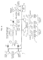
- FIG.1 is a block diagram showing a structure of a WDM transmission system according to a first embodiment of this invention.
- the system shown in FIG. 1 comprises an optical transmission node (optical transmitting apparatus) 1 and a discrete Raman optical amplifier 11.
- the optical transmission node 1 comprises a plurality of optical transmitters 11-1 through 11-m (m being an integer not smaller than two), two couplers 12-1 and 12-2, two isolators 13-1 and 13-2, and a polarization combiner (PBS: Polarization Beam Splitter) 14.
- PBS Polarization Beam Splitter
- the discrete Raman optical amplifier (hereinafter referred simply to "Raman amplifier") 2 comprises a plurality of pumping sources 21-1 through 21-i (i being an integer not smaller than two), two couplers 22-1 and 22-2, a polarization combiner (PBS) 23, a coupler 24, an optical transmission line (polarization maintaining high-nonlinearity fiber) 25, an isolator 26 and a pump light power control unit 29A.
- PBS polarization combiner
- coupler 24 an optical transmission line (polarization maintaining high-nonlinearity fiber) 25
- isolator 26 and a pump light power control unit 29A.
- the optical transmitters 11-1 through 11-k (k being an integer satisfying 2 ⁇ k ⁇ m) are in a group which transmits signal lights (wavelengths ⁇ 1 to ⁇ k) having the same polarization in a signal band "1" (first wavelength band), whereas the remaining optical transmitters 11-(k+1) through 11-m are in another group which transmits signal lights (wavelengths ⁇ k+1 to ⁇ m) having the same polarization in a different wavelength band "2" (second wavelength band), for example.
- the polarization of wave (also referred to as polarization of light) of the signal lights (first signal lights) in the signal band “1” and the polarization of wave of the signal lights (second signal lights) in the signal band “2" are set to be orthogonal.
- the relationship between the signal band “1” and the signal band “2” is that one is a shorter wavelength band, whereas the other is a longer wavelength band, for example.
- the couplers 12-1 and 12-2 are provided correspondingly to the signal bands "1" and “2", respectively.
- the coupler 12-1 couples (wavelength-multiplexes) the signal lights from the optical transmitters 11-1 through 11-k for the signal band "1.”
- the coupler 12-2 couples (wavelength-multiplexes) the signal lights from the optical transmitters 11-(k+1) through 11-m for the signal band "2.”
- the isolators 13-1 and 13-2 transmit output signal lights (wavelength-multiplexed lights) from the couplers 12-1 and 12-2 in only one direction to prevent feedback lights to the optical transmitters 11-j.
- the polarization combiner 14 combines the signal lights in the signal bands "1" and “2" while keeping their states of polarization. Since the polarization of the signal lights in the signal band "1” and the polarization of the signal lights in the signal band “2" are set to be orthogonal as stated above, the signal lights in the signal bands "1" and “2" are combined while keeping their orthogonal state, and outputted to the optical transmission line 25.
- a polarization maintaining high-nonlinearity fiber 25 which keeps the state of polarization of the signal lights to be transmitted and is less affected by the nonlinear effect, is used as the optical transmission line 25, whereby the signal lights in the signal bands "1" and "2" can be transmitted with low loss while keeping their polarizations (while keeping the above orthogonal state).
- pump lights #1 through #n pump light group “1”: first pump light group
- pump lights #1 through #n cover the signal band "1" with their gain characteristics (gain bands) to amplify the signal lights in the signal band "1,”
- pump lights #n+1 through #i from the remaining pumping sources 21-(n+1) through 21-i cover the signal band "2" with their gain bands to amplify the signal lights in the signal band "2," for example.
- the state of polarization of the signal band "1" and the state of polarization of the signal band “2” are set so that the polarization of the signal lights in the signal band “1” and the polarization of the pump lights #1 through #n in the pump light group “1” coincide with each other, and the polarization of the signal lights in the signal band “2” and the polarization of the pump lights #n+1 through #i in the pump light group “2" coincide with each other.
- Each of wavelength bands of the pump light groups "1" and “2” is set to an optimum wavelength band (for example, a band shifted toward the shorter wavelength by about 13.2 THz (100 nm) away from each of the signal bands “1” and “2”) according to each of the signal bands “1” and “2" to be amplified.
- the couplers 22-1 and 22-2 are disposed correspondingly to the pump light groups “1" and “2,” respectively.
- the coupler (first coupler) 22-1 couples the pump lights from the pumping sources 21-1 through 21-n constituting the pump light group "1.”
- the coupler (second coupler) 22-2 couples the pump lights from the pumping sources 21-(n+1) through 21-i constituting the pump light group "2.”
- the polarization combiner 23 combines output lights from the couplers 22-1 and 22-2 while keeping their polarization states, that is, their orthogonal state.
- the combined pump lights are introduced to the polarization maintaining high-nonlinearity fiber 25 (hereinafter referred simply to polarization maintaining fiber 25), which is a transmission line of the signal lights and is a Raman amplification medium, by the coupler (third coupler) 24, and transmitted within the polarization maintaining fiber 25 toward the optical transmission node 1 while keeping their orthogonal state.
- the isolator 26 prevents feedback light to the polarization maintaining fiber 25.
- the pump light power control unit 29A can control an output power (pump light power) of each of the pumping sources 21-1 through 21-i.
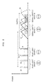
- a gain band having the gain peak caused by the stimulated Raman scattering effect is generated at a position shifted away from each of the pump light groups "1" and “2" toward the longer wavelength's side by about 13.2 THz (100 nm) in the polarization maintaining fiber 25, as schematically shown in FIG. 2, for example.
- a solid line 31 represents the gain characteristic of the pump light #1
- a solid line 32 the gain characteristic of the pump light #n
- a broken line 33 the gain characteristic of the pump light #n+1
- a broken line 34 the gain characteristic of the pump light #i, each of which signifies that the gain characteristic has a width (band) spreading from the peak value of the Raman gain.
- the pump light power control unit 29A controls (increases) the pump light power of the pump light group "2" in this situation, the generation efficiency of the stimulated Raman scattering becomes zero in an overlapped portion between gain characteristics (gain bands) 33 and 34, and the signal band "1" because the polarization of the pump light group "2" and the polarization of the signal lights in the signal band "1" are orthogonal even though the overlapped portion occurs.
- the pump light power control by the pump light power control unit 29A may be performed according to external setting from a maintenance consol or the like. Alternatively, output lights in each of the signal band "1" and "2" from the Raman amplifier 2 may be monitored, and the pump light power control may be performed automatically and adaptively according to a result of the monitoring.
- FIG. 4 is a block diagram showing a structure of a WDM transmission system according to a modification of the above-described first embodiment.
- the system shown in FIG. 4 corresponds to a structure of the Raman amplifier 2 when it has bidirectional pumping.
- the Raman amplifier 2 shown in FIG. 4 comprises, as an upstream-side pumping source unit 2-1 introducing a plurality of pump lights #1 through #i (i being an integer not smaller than two) for Raman amplification from the upstream side of the polarization maintaining fiber 25, a plurality of pumping sources 21-1 through 21-i, two couplers 22-1 and 22-2, a polarization combiner (PBS) 23 and a coupler 24, while comprising, as a downstream-side pumping source unit 2-2 introducing a plurality of pump lights #i+1 through #M (M being an integer not smaller than i+2) for Raman amplification from the downstream-side of the polarization maintaining fiber 25, a plurality of pumping sources 21-(i+1) through 21-M, two couplers 22-1 and 22-2, a polarization combiner (PBS) 23 and a coupler 24.
- PBS polarization combiner
- the signal band is divided into two signal bands "1" and "2.”
- the states of polarization of the signal bands "1” and “2”, and the pump light groups "1,” “2,” “3” and “4" are set, and the pump wavelength #j of each of the pumping sources 21-j is set so that signal lights in the signal band "1" are amplified high efficiently with pump light groups "1" (pumping sources 21-1 to 21-n) and "3” [pumping sources 21-(i+1) to 21-N], whereas signal lights in the signal band "2" are amplified highly efficiently with the pump light group “2” [pumping sources 21-(n+1) to 21-i] and "4" [pumping sources 21-(N+1) to 21-M].
- the pump wavelength #j of each of the pumping sources 21-J is set so that the polarization of the signal lights in the signal band "1" and the polarization of the pump light groups "1" and “3” coincide with each other, whereas the polarization of the signal lights in the signal band "2," which is orthogonal to the polarization of the signal lights in the signal band "1,” coincides with the polarization of the pump light groups "2" and "4".
- a reference character 29B denotes a pump light power control unit which can control a pump light power of each of the pumping sources 21-1 through 21-M, and structural elements denoted by like reference characters designate like or corresponding parts described above.
- the pump light power control by the pump light power control unit 29B may be performed according to external setting from a maintenance console or the like.
- an output light in each of the signal band "1" and "2" from the Raman optical amplifier 2 may be monitored, and the pump light power control may be performed automatically and adaptively according to a result of the monitoring.
- FIG. 5 is a block diagram showing a structure of a WDM transmission system according to a second embodiment of this invention.
- the WDM transmission system shown in FIG. 5 differs from the system described above with reference to FIG. 1 in that, in the optical transmission node 1, there are provided polarization controllers 15-1 through 15-m to adjust the states of the polarization of signal lights outputted from the respective optical transmitters 11-1 through 11-m before the signal lights are coupled by the couplers 12-1 and 12-2, and, in the Raman amplifier 2, there are provided polarization controllers 27-1 through 27-i to adjust pump lights #1 through #n and #n+1 through #i from the respective pumping sources 21-1 through 21-n and 21-(n+1) through 21-i before the pump lights are coupled by the couplers 22-1 and 22-2.
- the other components are identical or similar to those described above unless specifically mentioned.
- the signal lights outputted from the optical transmitters 11-1 through 11-m are divided into a signal band "1" and a signal band "2," states of polarization of which are orthogonal, as initial setting.
- Arrangement of wavelengths of the signal lights and the pump lights, and the polarization states of the signal lights and the pump lights #p are set so that the signal lights (first signal lights) in the signal band "1" are amplified highly efficiently with pump lights #1 through #n (first pump light group “1") from pumping sources (first pumping sources) 21-1 through 21-n, whereas the signal lights (second signal lights) in the signal band "2" are amplified highly efficiently by the remaining pumping sources (second pumping sources) 21-(n+1) through 21-i.
- each of the states of polarization of the signal bands "1" and “2,” and the pump light groups “1” and “2” is set (adjusted) so that the polarization of the signal lights in the signal band “1” and the polarization of the pump lights #1 through #n in the pump light group “1” are matched with each other, whereas the polarization of the signal lights in the signal band "2" and the polarization of the pump lights #n+1 through #i in the pump light group “2" are matched with each other.
- Each of wavelength bands (pump light wavelengths) of the pump light groups “1" and “2” is set to an optimum wavelength band [for example, a band shifted away from the signal band “1” or “2" toward the shorter wavelength's side by about 13.2 THz (100nm)] according to the signal band "1" or "2" to be amplified.
- the polarizing angle formed by the signal light and the pump light in the signal bands "1" or “2” is controlled to intensively increase the gain of the signal light in the signal band "1” or "2.” Accordingly, it is possible to control to decrease (or not to vary) the gain of each of the signal lights in the signal band "1" or "2.”
- the polarization controllers 27-1 through 27-i and 15-1 through 15-m fulfill a function as a polarization controlling means for controlling each polarizing angle formed by a signal light (first or second signal light) and a corresponding pump light (first or second pump iight).
- the polarizing angle formed by the polarization of a signal light in a certain signal band and the polarization of a pump light amplifying the signal light is controlled to break the agreement or the orthogonal relationship of polarization between the signal light and pump light, whereby the gain of a signal light within a specific signal band can be simply controlled.
- FIG. 7 is a block diagram showing a structure of a WDM transmission system according to a first modification of the second embodiment.
- the system shown in FIG. 7 differs from the system shown in FIG. 5 in that polarization controllers (first and second polarization controllers) are disposed on not the input's side but the output's side of the respective couplers 12-1 and 12-2 in the optical transmission node 1, and polarization controllers (first and second polarization controllers) 28-1 and 28-2 controlling polarizations of output lights from the couplers 22-1 and 22-2 are disposed on not the input's side but the output's side of the respective couplers 22-1 and 22-2 in the Raman amplifier 2.
- polarization controllers first and second polarization controllers
- first and second polarization controllers controlling polarizations of output lights from the couplers 22-1 and 22-2
- other structural components are the same as or similar to those described above unless specifically mentioned.
- each of the polarization controllers 16-1, 16-2, 28-1 and 28-2 functions as a polarization controlling means for controlling a polarizing angle which is formed by a signal light and a pump light, which collectively controls a polarization in a signal band or a pump light group as a unit, not controlling the polarization of each signal light in the signal bands "1" and "2" and the polarization of each pump light in the pump light groups "1" and "2.”
- This modification can largely decrease the number of necessary polarization controllers although it has less accuracy and freedom of polarization control, thus is advantageous with respect to the apparatus size and cost.
- the polarization controller is provided to each of the signal bands and the pump light groups.
- either one of the optical transmission node 1 or the Raman amplifier 2 may have the structure shown in FIG. 5, that is, the polarization controller may be provided to each of the signal bands in the optical transmission node 1 or to each of the pump light groups in the Raman amplifier 2.
- the polarization controllers are provided to both the optical transmission node 1 and the Raman amplifier 2. However, even if the polarization controllers are provided to either one of the optical transmission node 1 or the Raman amplifier 2, it is possible to control a polarizing angle formed by the polarization of signal lights and the polarization of pump lights.
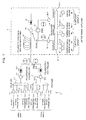
- control on the polarization controllers 16-1, 16-2, 28-1 and 28-2 can be done by monitoring the power of each signal light in the signal bands "1" and "2" on the output's side of the Raman amplifier 2, and determining a control quantity for each of the polarization controllers 16-1, 16-2, 28-1 and 28-2 on the basis of a result of the monitoring, as shown in FIG. 8, for example.
- a branching coupler 51 branching a part of an output light from the Raman amplifier 2 as a monitor light
- a polarization beam splitter (or a demultiplexer) 52 demultiplexes the monitor light into the signal bands "1" and "2”
- light receiving elements 53 and 54 such as PIN photodiodes or the like receiving the monitor lights in the signal bands "1” and “2” and outputting electric signals according to their quantities of received light
- an arithmetic unit 55 determining control quantities for the polarization controllers 16-1, 16-2, 28-1 and 28-2 in arithmetic operation on the basis of outputs from the light receiving elements 53 and 54.
- the polarization control unit there are provided the branching coupler 51 and the light receiving elements 53 and 54 as a monitoring unit for monitoring each of the signal light groups of the signal bands "1" and "2" from the output light of the polarization maintaining fiber 25, and the arithmetic unit 55 as a control unit for generating control signals for the polarization controllers 16-1, 16-2, 28-1 and 28-2 on the basis of a result of the monitoring by the monitoring unit.
- the arithmetic unit 55 adaptively determines a control quantity required by each of the polarization controllers 16-1, 16-2, 28-1 and 28-2 so that a difference (error) between the signal band "1” or “2" and the target gain becomes null, whereby the polarization controllers 16-1, 16-2, 28-1 and 28-2 are adaptively controlled.
- This controlling method can be applied to the system structure described above with reference to FIG. 5, of course.
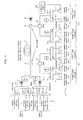
- FIG. 9 is a block diagram showing a structure of a WDM transmission system according to a third embodiment of this invention.
- the system shown in FIG. 9 differs from the structure shown in FIG. 1 in that, in the optical transmission node 1, the optical transmitters 1 through m are grouped into an odd number signal wavelength group [ ⁇ 1, ⁇ 3, ... and ⁇ (2k-1)] made up of optical transmitters 11-1, 11-3 ... and 11-(2k-1), and an even number signal optical wavelength group ( ⁇ 2, ⁇ 4, ... and ⁇ 2k) made up of optical transmitters 11-2, 11-4 ...
- the polarization of the odd number signal optical wavelength group and the polarization of the even number signal wavelength group are made orthogonal, and signal lights at the odd wavelengths are coupled by the coupler 12-1, whereas signal lights at odd wavelengths are coupled by the coupler 12-2.
- the system shown in FIG. 9 differs from the system shown in FIG. 1 in that, in the Raman amplifier 2, the pumping sources 21-1 through 21-2n are grouped into an odd number pump light wavelength group made up of pumping sources 21-1, 21-3 ... and 21-(2n-1), and an even number pump light wavelength group made up of pumping sources 21-2, 21-4 ... and 21-2n, the polarization of the odd number pump light wavelength group and the polarization of the odd number signal optical wavelength group are matched with each other, the polarization of the even number pump light wavelength group and the polarization of the even number pump light wavelength group are matched with each other, and the pump lights #1, #3 ... and #2n-1 at odd number wavelengths are coupled by the coupler 22-1, whereas pump lights #2, #4 ... and #2n at even number wavelengths are coupled by the coupler 22-2.
- Each of the pump lights #1 through #2n is at a position shifted away from the wavelength arranged position of a corresponding signal light toward the shorter wavelength by about 13.2 THz (100 nm), for example.
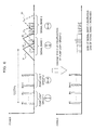
- each signal light in the odd number signal optical wavelength group and each signal light in the even number signal optical number group having the polarization 90 degree away from that of the former signal light are alternately arranged in the polarization maintaining fiber 25, and each of the pump light wavelengths is set at a position shifted away from the wavelength arranged position of a corresponding signal light toward the shorter wavelength by about 13.2 THz (100 nm) so that the gain peak brought by the pump light can be obtained at the wavelength arranged position of the signal light, as schematically shown in FIG. 10, for example.
- a solid line 41 represents the gain characteristic of a pump light #1, a broken line 42 the gain characteristic of a pump light #2, a solid line 43 the gain characteristic of a pump light #3 and a broken line 44 the gain characteristic of a pump light #4.
- a predetermined wavelength spacing is provided between the signal light and the pump light in order to prevent not less than two signal lights having the same polarization from being amplified by the gain characteristic of one pump light.
- the pump light power control unit 29A controls the output power of the pumping source 21-2 (increased) by the pump light power control unit 29A to increase the power of the pump light #2
- the pump light power control by the pump light power control unit 29A may be performed according to external setting from a maintenance console or the like.
- each of the signal bands "1" and "2" in an output light from the Raman optical amplifier 2 may be monitored, and the pump light power control may be performed automatically and adaptively according to a result of the monitoring.
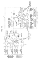
- FIG. 12 is a block diagram showing a structure of a WDM transmission system according to a modification of the third embodiment described above.
- the system shown in FIG. 12 differs in structure from the system shown in FIG. 9 in that polarization controllers 15-1 through 15-2k for adjusting the states of polarization of signal lights outputted from the optical transmitters 11-1 through 11-2k before the signal lights are coupled by the couplers 12-1 and 12-2 are provided in the optical transmission node 1, and polarization controllers 27-1 through 27-2n for adjusting pump lights #1n through #2n from the pumping sources 21-1 through 21-2n before the pump lights are coupled by the couplers 22-1 and 22-2 are provided in the Raman amplifier 2, like the system structure shown in FIG. 5.
- like reference characters designate like or corresponding parts described above.
- the states of polarization of the odd number signal light wavelength group and the even number signal wavelength group are set so that signal lights in the odd number signal light wavelength group are amplified with pump lights in the odd number pump light wavelength group, whereas signal lights in the even number signal wavelength group are amplified with pump lights in the even number pump light wavelength group whose polarization is orthogonal to the polarization of the odd number pump light wavelength group.
- the polarization controller 27-2 when only the polarization of the pump light #2 is controlled by the polarization controller 27-2, for example, the generation efficiency of the stimulated Raman scattering drops from the peak because the polarization of the pump light #2 shifts from the coincident state with the polarization of the signal light ⁇ 2 to be amplified, the gain of the signal light ⁇ 2 is thus decreased.
- the polarization of a signal light present within the gain characteristic 42 (refer to FIG.
- this embodiment it is possible to simply control the gain of a signal light at a specific wavelength by controlling a polarizing angle formed by the signal light at a certain wavelength and a corresponding pump light to break the coincide state or the orthogonal relationship of the polarization between the signal light and the pump light.
- the polarization control in this case can be adaptively performed by applying a manner similar to that described above with reference to FIG. 8, as well.
- the gain control on a signal light is performed by controlling either the pump light power or the polarizing angle.
- both of the pump light power and the polarizing angle may be controlled.
- the signal band is divided into two.
- the signal band may be divided into three or more.
- the polarizations of neighboring signal bands of signal lights are made orthogonal, and the polarization of the signal lights is matched with the polarization of corresponding pump lights in each of the signal band, whereby the same or similar working functions can be obtained.
- an input light inputted to the polarization maintaining fiber 25 as being an amplification medium is a signal light, that is, a modulated signal light.
- the present invention is not limited to this.
- this invention can be applied to a case in which the inputted light is a light other than the signal light such as a carrier light, a pilot light or the like, and can provide the same working function as above.
- two or more pump lights are prepared to amplify the signal band "1" ("2").
- only one pump light can be used to amplify a plurality of lights in a certain signal band (it is not always necessary to prepare more than one pump lights).
- polarizations of the pair of pump lights are orthogonal to each other, and that polarizations of the pair of signal lights are also orthogonal to each other.
- each of the pump lights and its corresponding signal light, which is to be amplified with the pump light have polarizations identical to each other, such orthogonal relationships between the pump light pair and between the signal light pair are not always necessary.
- this invention can provide a Raman optical amplifier and an optical transmission system which can control, simply and independently, the gain of a wavelength or a wavelength band of a specific input light by controlling the pump light power or the polarizing angle formed by the input light and the pump light, without affecting the other wavelengths or wavelength bands. Therefore, this invention is very useful in the field of optical communication techniques.
Landscapes
- Physics & Mathematics (AREA)
- Electromagnetism (AREA)
- Engineering & Computer Science (AREA)
- Plasma & Fusion (AREA)
- Optics & Photonics (AREA)
- Computer Networks & Wireless Communication (AREA)
- Signal Processing (AREA)
- Optical Modulation, Optical Deflection, Nonlinear Optics, Optical Demodulation, Optical Logic Elements (AREA)
- Lasers (AREA)
- Optical Communication System (AREA)
Abstract
Description
Claims (19)
- A Raman optical amplifier comprising:an amplification medium (25) inputted a first light (any one of λ1 through λk) and a second light (any one of λk+1 through λm) polarizations of which are orthogonal; anda pumping means for inputting, to said amplification medium (25), a first pump light (any one of #1 through #n) a polarization of which coincides with the polarization of said first light (any one of λ1 through λk), and a second pump light (any one of #n+1 through #i) a polarization of which coincides with the polarization of said second light (any one ofλk+1 through λm).
- A Raman optical amplifier comprising:an amplification medium (25) inputted a first light group (λ1 through λk) having the same polarization in a first wavelength band and a second light group (λk+1 through λm) in a second wavelength band having a polarization orthogonal to the polarization of said first light group (λ1 through λk); anda pumping means for inputting a first pump light (any one of #1 through #n) coinciding with the polarization of said first light group (λ1 through λk), and a second pump light (any one of #n+1 through #i) coinciding with the polarization of said second light group (λk+1 through λm) to said amplification medium (25).
- The Raman optical amplifier according to claim 2, wherein said pumping means inputs a plurality of said first pump lights (#1 through #n) and a plurality of said second pump lights (#n+1 through #i) to said amplification medium (25).
- The Raman optical amplifier according to any one of claims 1 through 3 further comprising:a pump light power controlling means (29A) for controlling an output power of each of said pump lights (#1 through #i).
- The Raman optical amplifier according to any one of claims 1 through 3 further comprising:a polarization controlling means for controlling a polarizing angle formed by said first light (any one of λ1 through λk) and said first pump light (#1 through #n) and a polarizing angle formed by said second light (any one of λk through λm) and said second pump light (#n+1 through #i).
- The Raman optical amplifier according to claim 5, wherein said pumping means comprises:said polarization controlling means comprises:a first pumping source (any one of 21-1 through 21-n) for outputting said first pump light (#1 through #n);a second pumping source [any one of 21-(n+1) through 21-i] for outputting said second pump light (#n+1 through #i);a polarization combiner (23) for combining output lights of said pumping sources (21-1 through 21-i) while keeping polarizations thereof; anda coupler (24) for introducing an output light of said polarization combiner (23) to said amplification medium (25);a polarization controller (27-1 through 27-i) disposed to each of said pumping sources (21-1 through 21-i).
- The Raman optical amplifier according to claim 5, wherein said pumping means comprises:said polarization controlling means comprises:a plurality of first pumping sources (21-1 through 21-n) for outputting a plurality of said first pump lights (#1 through #n);a plurality of second pumping sources [21-(n+1) through 21-i] for outputting a plurality of said second pump lights (#n+1 through #i);a first coupler (22-1) for coupling output lights of said first pumping sources (21-1 through 21-n);a second coupler (22-2) for coupling output lights of said second pumping sources [21-(n+1) through 21-i];a polarization combiner (23) for combining output lights of said couplers (22-1, 22-2) while keeping polarizations thereof; anda third coupler (24) for introducing an output light of said polarization combiner (23) into said amplification medium (25);a first polarization controller (28-1) for controlling a polarization of the output light of said first coupler (22-1);a second polarization controller (28-2) for controlling a polarization of the output light of said second coupler (22-2).
- The Raman optical amplifier according to any one of claims 5 through 7, wherein said polarization controlling means comprises:a monitoring unit (51 through 54) for monitoring each of said first light group (λ1 through λk) and said second light group (λk+1 through λm) in an output light of said amplification medium (25); anda controlling unit (55) for generating control signals for said polarization controllers (27-1 through 27-i, 28-1, 28-2) on the basis of a result of monitoring by said monitoring unit (51 through 54).
- The Raman optical amplifier according to any one of claims 1 through 8, wherein said amplification medium (25) is a polarization maintaining fiber maintaining states of polarization of said first and second lights (λ1 through λk and λk+1 through λm) and said pump lights (#1 through #i).
- An optical transmission system using a Raman optical amplifier comprising:an optical transmitting apparatus (1) for transmitting a first light (any one of λ1 through λk) and a second light (any one of λk+1 through λm) polarizations of which are orthogonal; andsaid Raman optical amplifier (2) comprising:an amplification medium (25) inputted said lights (any one of λ1 through λk and any one of λk+1 through λm) from said optical transmitting apparatus (1); anda pumping means for inputting a first pump light (any one of #1 through #n) coinciding with a polarization of said first light (any one of λ1 through λk) and a second pump light (any one of #n+1 through #i) coinciding with a polarization of said second light (any one of λk+1 through λm) to said amplification medium (25).
- An optical transmission system using a Raman optical amplifier comprising:an optical transmitting apparatus (1) for transmitting a first light group (λ1 through λk) having the same polarization in a first wavelength band, and a second light group (λk+1 through λm) in a second wavelength band having a polarization orthogonal to the polarization of said first light group (λ1 through λk);said Raman optical amplifier (2) comprising:an amplification medium (25) inputted said light groups (λ1 through λm) from said optical transmitting apparatus (1); anda pumping means for inputting a first pump light (any one of #1 through #n) coinciding with the polarization of said first light group (λ1 through λk), and a second pump light (any one of #n+1 through #i) coinciding with the polarization of said second light group (λk+1 through λm) to said amplification medium (25).
- The optical transmission system using a Raman optical amplifier according to claim 11, wherein said pumping means inputs a plurality of said first pump lights (#1 through #n) and a plurality of said second pump lights (#n+1 through #i) to said amplification medium (25).
- The optical transmission system using a Raman optical amplifier according to any one of claims 10 through 12, wherein said Raman optical amplifier (2) comprises:a pump light power controlling means (29A) for controlling an output power of each of said pump lights (#1 through #i).
- The optical transmission system using a Raman optical amplifier according to any one of claims 10 through 12 further comprising:a polarization controlling means for controlling a polarizing angle formed by said first light (any one of λ1 through λk) and said first pump light (any one of #1 through #n), and a polarizing angle formed by said second light (any one of λk+1 through λm) and said second pump light (any one of #n+1 through #i).
- The optical transmission system using a Raman optical amplifier according to claim 14, wherein said polarization controlling means comprises:a first optical polarization controller (any one of 15-1 through 15-k) for controlling a polarization of said first light (any one of λ1 through λk); anda second optical polarization controller [any one of 15-(k+1) through 15-m] for controlling a polarization of said second light (any one of λk+1 through λm);said first optical polarization controller (any one of 15-1 through 15-k) and said second optical controller [any one of 15-(k+1) through 15-m] being disposed in said optical transmitting apparatus (1).
- The optical transmission system using a Raman optical amplifier according to claim 14, wherein said polarization controlling means comprises:a first pump light polarization controller (any one of 27-1 through 27-n) for controlling a polarization of said first pump light (any one of #1 through #n); anda second pump light polarization controller [any one of 27-(n+1) through 27-i] for controlling a polarization of said second pump light (any one of #n+1 through #i);said first pump light polarization controller (any one of 27-1 through 27-n) and said second pump light polarization controller [any one of 27-(n+1) through 27-i] being disposed in said Raman optical amplifier (2).
- The optical transmission system using a Raman optical amplifier according to any one of claims 10 through 16, wherein said amplification medium (25) is a polarization maintaining fiber maintaining states of polarization of said first and second lights (λ1 through λk and λk+1 through λm) and said pump lights (#1 through #i).
- A Raman optical amplification method comprising the steps of:inputting a first light (any one of λ1 through λk) and a second light (any one of λk+1 through λm), polarizations of which are orthogonal, to an amplification medium (25);inputting a first pump light (any one of #1 through #n) coinciding with a polarization of said first light (any one of λ1 through λk), and a second pump light (any one of #n+1 through #i) coinciding with a polarization of said second light (any one of λk+1 through λm) to said amplification medium (25); andcontrolling gains of said first and second lights (any one of λ1 through λk and any on e of λk+1 through λm) by controlling output powers of said pump lights (any one of #1 through #n and any one of #n+1 through #i).
- A Raman optical amplification method for amplifying a light transmitted through an amplification medium (25) by inputting a pump light, said Raman optical amplification method comprising the steps of:controlling a polarizing angle formed by said light transmitted through said amplification medium (25) and said pump light to control an amplification gain.
Applications Claiming Priority (2)
| Application Number | Priority Date | Filing Date | Title |
|---|---|---|---|
| JP2004029254 | 2004-02-05 | ||
| JP2004029254A JP4560300B2 (en) | 2004-02-05 | 2004-02-05 | Raman optical amplifier, optical transmission system using the same, and Raman optical amplification method |
Publications (3)
| Publication Number | Publication Date |
|---|---|
| EP1562313A2 true EP1562313A2 (en) | 2005-08-10 |
| EP1562313A3 EP1562313A3 (en) | 2005-11-02 |
| EP1562313B1 EP1562313B1 (en) | 2007-03-14 |
Family
ID=34675523
Family Applications (1)
| Application Number | Title | Priority Date | Filing Date |
|---|---|---|---|
| EP04015376A Expired - Lifetime EP1562313B1 (en) | 2004-02-05 | 2004-06-30 | Raman optical amplifier, optical transmission system using the same, and Raman optical amplification method |
Country Status (4)
| Country | Link |
|---|---|
| US (1) | US7245422B2 (en) |
| EP (1) | EP1562313B1 (en) |
| JP (1) | JP4560300B2 (en) |
| DE (1) | DE602004005301T2 (en) |
Cited By (1)
| Publication number | Priority date | Publication date | Assignee | Title |
|---|---|---|---|---|
| WO2017155979A1 (en) * | 2016-03-10 | 2017-09-14 | Alcatel-Lucent Usa Inc. | Optical pumping technique |
Families Citing this family (7)
| Publication number | Priority date | Publication date | Assignee | Title |
|---|---|---|---|---|
| KR100592880B1 (en) * | 2004-12-10 | 2006-06-26 | 한국전자통신연구원 | Parallel Raman Optical Amplifier |
| US7724421B2 (en) * | 2005-06-16 | 2010-05-25 | Alcatel-Lucent Usa Inc. | Phase sensitive optical amplification |
| EP1788728A1 (en) * | 2005-11-18 | 2007-05-23 | Alcatel Lucent | Raman amplifier and optical transmission system |
| US20120257899A1 (en) * | 2011-04-06 | 2012-10-11 | Tyco Electronics Subsea Communications Llc | Orthogonal band launch for repeaterless systems |
| US8912475B2 (en) * | 2011-11-22 | 2014-12-16 | Harris Corporation | Optical sensing system with a phase sensitive amplifier and associated methods |
| JP2013134320A (en) * | 2011-12-26 | 2013-07-08 | Fujitsu Telecom Networks Ltd | Excitation light source for raman amplification, raman amplifier, and optical transmission system |
| PL428292A1 (en) * | 2018-12-20 | 2020-06-29 | Dawis It Spółka Z Ograniczoną Odpowiedzialnością | Method and transmission system for improved one-way or two-way data transmission in the telecommunications network, polarization attractor configuration, computer program and computer program product |
Family Cites Families (15)
| Publication number | Priority date | Publication date | Assignee | Title |
|---|---|---|---|---|
| US5035481A (en) * | 1990-08-23 | 1991-07-30 | At&T Bell Laboratories | Long distance soliton lightwave communication system |
| US6052393A (en) * | 1996-12-23 | 2000-04-18 | The Regents Of The University Of Michigan | Broadband Sagnac Raman amplifiers and cascade lasers |
| US6618192B2 (en) * | 1998-06-16 | 2003-09-09 | Xtera Communications, Inc. | High efficiency raman amplifier |
| US6344922B1 (en) | 1998-07-21 | 2002-02-05 | Corvis Corporation | Optical signal varying devices |
| EP2306605B1 (en) * | 1998-07-23 | 2012-05-23 | The Furukawa Electric Co., Ltd. | Pumping unit for a Raman amplifier and Raman amplifier comprising the same |
| JP4115027B2 (en) * | 1998-07-23 | 2008-07-09 | 古河電気工業株式会社 | Excitation light generation means, Raman amplifier and optical repeater using the same |
| JP2001044934A (en) | 1999-08-04 | 2001-02-16 | Nippon Telegr & Teleph Corp <Ntt> | WDM optical transmitter |
| JP2001230480A (en) * | 2000-02-14 | 2001-08-24 | Nippon Telegr & Teleph Corp <Ntt> | Pump light source and optical fiber communication system using Raman amplification |
| US6414786B1 (en) * | 2000-03-27 | 2002-07-02 | Tycom (Us) Inc. | Method and apparatus for reducing polarization dependent gain in Raman amplification |
| JP2002296447A (en) * | 2001-03-30 | 2002-10-09 | Fujikura Ltd | Polarization multiplexer / demultiplexer and optical amplifier |
| JP4161621B2 (en) | 2001-06-29 | 2008-10-08 | 住友電気工業株式会社 | Excitation light source unit, Raman amplifier, and optical transmission system |
| EP1454436B1 (en) | 2001-08-16 | 2007-02-21 | Telefonaktiebolaget LM Ericsson (publ) | Optical amplifier |
| JP4191035B2 (en) * | 2001-10-10 | 2008-12-03 | 古河電気工業株式会社 | Unpolarized laser diode module |
| EP1341324B1 (en) * | 2002-02-21 | 2007-04-25 | Alcatel Lucent | Optical fiber transmission system using raman amplification |
| JP3923343B2 (en) * | 2002-03-15 | 2007-05-30 | 三菱電機株式会社 | Single fiber bidirectional optical transmission system |
-
2004
- 2004-02-05 JP JP2004029254A patent/JP4560300B2/en not_active Expired - Fee Related
- 2004-06-23 US US10/873,232 patent/US7245422B2/en not_active Expired - Lifetime
- 2004-06-30 EP EP04015376A patent/EP1562313B1/en not_active Expired - Lifetime
- 2004-06-30 DE DE602004005301T patent/DE602004005301T2/en not_active Expired - Lifetime
Cited By (2)
| Publication number | Priority date | Publication date | Assignee | Title |
|---|---|---|---|---|
| WO2017155979A1 (en) * | 2016-03-10 | 2017-09-14 | Alcatel-Lucent Usa Inc. | Optical pumping technique |
| CN109155673A (en) * | 2016-03-10 | 2019-01-04 | 诺基亚美国公司 | Optical pumping technology |
Also Published As
| Publication number | Publication date |
|---|---|
| EP1562313B1 (en) | 2007-03-14 |
| DE602004005301T2 (en) | 2007-08-30 |
| DE602004005301D1 (en) | 2007-04-26 |
| US7245422B2 (en) | 2007-07-17 |
| EP1562313A3 (en) | 2005-11-02 |
| US20050174630A1 (en) | 2005-08-11 |
| JP4560300B2 (en) | 2010-10-13 |
| JP2005221737A (en) | 2005-08-18 |
Similar Documents
| Publication | Publication Date | Title |
|---|---|---|
| US7133193B2 (en) | Optical transmission systems including optical amplifiers, apparatuses and methods | |
| EP1187276B1 (en) | Optical amplifier for wide band raman amplification of wavelength division multiplexed (WDM) signal lights | |
| EP1248392B1 (en) | Optical amplifier device and bidirectional wavelength division multiplexing optical communication system using the same | |
| JP4551007B2 (en) | Raman amplifier and optical transmission system using the same | |
| US6606337B1 (en) | Multiple band Raman amplifier pump source | |
| US6636659B2 (en) | Optical amplification apparatus and optical transmission system | |
| US8041231B2 (en) | Supervisory controlling method and supervisory controlling system of optical repeater | |
| JP4626918B2 (en) | Raman optical repeater | |
| US20050024714A1 (en) | Optical amplifier with pump light source control for Raman amplification | |
| US6690504B1 (en) | System and method for controlling spectral distribution of output power in a Raman amplifier | |
| EP1348266B1 (en) | Control scheme for long wavelength channels in wideband wdm optical fiber transmission system | |
| JP2000515688A (en) | Automatic feedback gain control of doped fiber amplifiers. | |
| JP3779691B2 (en) | Broadband erbium-doped optical fiber amplifier and wavelength division multiplexing optical transmission system employing the same | |
| US6147796A (en) | Method for determining transmission parameters for the data channels of a WDM optical communication system | |
| EP1562313B1 (en) | Raman optical amplifier, optical transmission system using the same, and Raman optical amplification method | |
| US20060061855A1 (en) | Optical node | |
| US7692850B1 (en) | Lumped-Raman amplification structure for very wideband applications | |
| US20230344541A1 (en) | Dummy light signal generation apparatus and method, and reconfigurable optical add/drop multiplexer | |
| JP3980617B2 (en) | Optical communication system and optical amplifier |
Legal Events
| Date | Code | Title | Description |
|---|---|---|---|
| PUAI | Public reference made under article 153(3) epc to a published international application that has entered the european phase |
Free format text: ORIGINAL CODE: 0009012 |
|
| AK | Designated contracting states |
Kind code of ref document: A2 Designated state(s): AT BE BG CH CY CZ DE DK EE ES FI FR GB GR HU IE IT LI LU MC NL PL PT RO SE SI SK TR |
|
| AX | Request for extension of the european patent |
Extension state: AL HR LT LV MK |
|
| PUAL | Search report despatched |
Free format text: ORIGINAL CODE: 0009013 |
|
| AK | Designated contracting states |
Kind code of ref document: A3 Designated state(s): AT BE BG CH CY CZ DE DK EE ES FI FR GB GR HU IE IT LI LU MC NL PL PT RO SE SI SK TR |
|
| AX | Request for extension of the european patent |
Extension state: AL HR LT LV MK |
|
| RIC1 | Information provided on ipc code assigned before grant |
Ipc: 7H 04B 10/17 A Ipc: 7H 01S 3/30 B |
|
| 17P | Request for examination filed |
Effective date: 20051102 |
|
| AKX | Designation fees paid |
Designated state(s): DE FR GB |
|
| GRAP | Despatch of communication of intention to grant a patent |
Free format text: ORIGINAL CODE: EPIDOSNIGR1 |
|
| GRAS | Grant fee paid |
Free format text: ORIGINAL CODE: EPIDOSNIGR3 |
|
| GRAA | (expected) grant |
Free format text: ORIGINAL CODE: 0009210 |
|
| AK | Designated contracting states |
Kind code of ref document: B1 Designated state(s): DE FR GB |
|
| REG | Reference to a national code |
Ref country code: GB Ref legal event code: FG4D |
|
| REF | Corresponds to: |
Ref document number: 602004005301 Country of ref document: DE Date of ref document: 20070426 Kind code of ref document: P |
|
| ET | Fr: translation filed | ||
| PLBE | No opposition filed within time limit |
Free format text: ORIGINAL CODE: 0009261 |
|
| STAA | Information on the status of an ep patent application or granted ep patent |
Free format text: STATUS: NO OPPOSITION FILED WITHIN TIME LIMIT |
|
| 26N | No opposition filed |
Effective date: 20071217 |
|
| REG | Reference to a national code |
Ref country code: FR Ref legal event code: PLFP Year of fee payment: 13 |
|
| REG | Reference to a national code |
Ref country code: FR Ref legal event code: PLFP Year of fee payment: 14 |
|
| REG | Reference to a national code |
Ref country code: FR Ref legal event code: PLFP Year of fee payment: 15 |
|
| PGFP | Annual fee paid to national office [announced via postgrant information from national office to epo] |
Ref country code: DE Payment date: 20190618 Year of fee payment: 16 |
|
| PGFP | Annual fee paid to national office [announced via postgrant information from national office to epo] |
Ref country code: FR Payment date: 20190510 Year of fee payment: 16 |
|
| PGFP | Annual fee paid to national office [announced via postgrant information from national office to epo] |
Ref country code: GB Payment date: 20190626 Year of fee payment: 16 |
|
| REG | Reference to a national code |
Ref country code: DE Ref legal event code: R119 Ref document number: 602004005301 Country of ref document: DE |
|
| GBPC | Gb: european patent ceased through non-payment of renewal fee |
Effective date: 20200630 |
|
| PG25 | Lapsed in a contracting state [announced via postgrant information from national office to epo] |
Ref country code: GB Free format text: LAPSE BECAUSE OF NON-PAYMENT OF DUE FEES Effective date: 20200630 Ref country code: FR Free format text: LAPSE BECAUSE OF NON-PAYMENT OF DUE FEES Effective date: 20200630 |
|
| PG25 | Lapsed in a contracting state [announced via postgrant information from national office to epo] |
Ref country code: DE Free format text: LAPSE BECAUSE OF NON-PAYMENT OF DUE FEES Effective date: 20210101 |