BACKGROUND OF THE INVENTION
1. Field of the Invention
The present invention relates to a fuel cell using
liquid fuel, more specifically to a fuel cell suitably
used as an electric source for portable electronic
apppliances such as cellular phones and note type
personal computers and a small-sized portable electric
source for appliances using small electric power.
2. Description of the Related Art
In general, a fuel cell comprises a cell part on
which an air electrode layer, an electrolyte layer and a
fuel electrode layer are laminated, a fuel-supplying part
for supplying fuel as a reducing agent to the fuel
electrode layer and an air-supplying part for supplying
air as an oxidizing agent to the air electrode layer, and
it is an electric cell in which electrochemical reaction
is caused in a cell between fuel and oxygen in the air to
obtain electric power in the outside. Cells of various
types are developed.
In recent years, because of a rise in consciousness
to environmental problems and energy saving, it is
investigated to use a fuel cell as a clean energy source
for various uses. Particularly in the development of a
fuel cell system as an electric source for small-sized
portable appliances, reduction in a size of the whole
system, a rise in an output and no generation of noise
are important subjects.
In a conventional fuel cell, sheet-like cells (unit
cell) 1, 1--- having an electrolyte membrane/electrode
junction assembly (MEA: membrane electrode assembly) are
laminated, as shown in Fig. 17, via tabular separators 2,
2--- to attempt reduction in a size of a cell stack and
increase in a output density thereof. In this case,
auxiliary devices such as a pump and a blower are
necessary in order to allow liquid fuel and oxidizing
agent gas (for example; air and oxygen) to flow through
passages 2a for the liquid fuel and passages 2b for the
oxidizing agent gas which are formed in thin tabular
separators 2 interposed between the unit cells 1.
In a fuel cell of the above type, there are the
problems that it is difficult to reduce a size of the
system because auxiliary devices are required and that a
large part of a cell output is consumed at power for the
auxiliary devices and noise is generated from a pump and
a blower.
On the other hand, known as a fuel cell for small-sized
portable appliances is, for example, as shown in
Fig, 18, a fuel cell of a self-operating type which has
at least one vent hole 4 on a wall face of a liquid fuel
vessel 3 and which installs plural sheet-like single
cells (unit cells) 5, 5--- having MEA on the wall face of
the above liquid fuel vessel 3 and electrically connects
the each unit cells and which makes use of a capillary
phenomenon of liquid fuel 6 and convention and diffusion
of oxidizing agent gas without using auxiliary devices
(for example, Japanese Patent Application Laid-Open No.
100315/2003).
However, as a separator can not be used in a fuel
cell of the above type, the sheet-like unit cells can not
help being connected on a two-dimensional plane, and as a
result, caused is the problem that cell junction
(stacking) making effective use of a three-dimensional
space can not be carried out.
On the other hand, known is a fuel cell in which
liquid fuel is introduced into a unit cell that contacts
with a common absorber at one end of each unit cell by
capillary force and in which the liquid fuel is then
vaporized in a fuel-vaporizing layer and used (for
example, Japanese Patent Application Laid-Open No.
102069/2001). In the above fuel cell, however, a
shortage in followability of fuel which is a fundamental
problem is not improved, and it has the problems that
liquid fuel is instably fed when the fuel is fed to a
fuel electrode to bring about variation in an output
value during operation and that it is difficult to reduce
a size thereof to such an extent that it can be loaded in
portable appliances while maintaining stable
characteristics.
As described above, in the development of a
conventional fuel cell system as an electric source for
small-sized portable appliances, the existing situation
is that problems such as reduction in a size of the whole
system, a rise in an output and no generation of noise
have not yet been satisfactorily solved and that a fuel
cell which can exhibit more reduction in a size and more
rise in an output is eagerly desired to appear.
In light of the problems of the conventional
techniques described above and the existing situations
thereof, the present invention intends to solve them, and
an object thereof is to provide a fuel cell which
attempts reduction in a size of the whole fuel cell
system as an electric source for small-sized portable
appliances and a rise in an output and which generates
less noises.
SUMMARY OF THE INVENTION
Intensive researches repeated by the present
inventors in order to solve the conventional problems
described above have resulted in finding that a fuel cell
meeting the object described above can be obtained by
assuming a structure which comprises a unit cell in which
the respective layers of electrode/electrolyte/electrode
are formed on the surface of a base material of specific
physical properties having electric conductivity in a
part or the whole part, or a connected assembly prepared
by connecting two or more above unit cells and in which
the above base material of the specific physical
properties is impregnated with liquid fuel and an
electrode surface formed on the outside surface of the
base material is exposed to oxidizing agent gas. Thus,
the present invention has come to be completed.
That is, the present invention comprises the
following items (1) to (11).
According to the present invention, plural cells
can be connected by only a part of cell end parts by
allowing a carbonaceous porous body having electrical
conductivity to have functions as an electrode·collector,
an impregnating medium for liquid fuel and oxidizer gas
and a cell supporter in common, and a separator can be
made unnecessary. Accordingly, the above space which is
not necessitated can be used as a field for convecting
and diffusing oxidizing agent gas or liquid fuel, whereby
a fuel cell which can actualize reduction in a size of a
fuel cell system and a rise in an output is provided.
BRIEF DESCRIPTION OF DRAWINGS
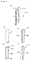
Fig. 1 (a) is a perspective drawing showing one
example of the embodiments of a cell of a fuel cell, and
(b) to (e) are schematic cross-sectional drawings showing
the forms of the base material in a traverse cross-sectional
mode.
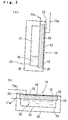
Fig. 2 (a) and (b) show a fuel cell of the first
embodiment, wherein (a) shows vertical configuration, and
(b) shows horizontal configuration in a vertical cross-sectional
mode.
Fig. 3 (a) is a perspective drawing showing a form
in which a cell is turned into a cartridge form, and (b)
is a partial cross-sectional drawing showing it by a
traverse cross-sectional mode.
Fig. 4 (a) is a perspective drawing showing a form
in which two cells are constituted into one unit, and (b)
is a perspective drawing showing a structure in which a
partition wall for controlling absorption of liquid fuel
and diffusion of air is provided at an opposite side
having no electrode layer in the cell.
Fig. 5 is a perspective drawing showing a form in
which the cells turned into a cartridge form in Fig. 3
are serially connected.
Fig. 6 is a perspective drawing showing a form in
which the cells turned into a cartridge form in Fig. 3
are parallel connected.
Fig. 7 is a perspective drawing showing a form in
which five cells turned into a cartridge form in Fig. 3
are serially connected.
Fig. 8 (a) to (c) are schematic drawings showing a
structure in which the cells having the form shown in Fig.
6 are installed in a fuel tank and a holder member and
showing the forms of vertical configuration in which the
fuel tank is situated in an upper part or a lower part
and horizontal configuration.
Fig. 9 is a schematic drawing of a fuel cell
showing another embodiment of the present invention.
Fig. 10 is a schematic drawing of a fuel cell
showing another embodiment of the present invention.
Fig. 11 (a) is a schematic drawing of a fuel cell
showing another embodiment of the present invention; (b)
is a schematic drawing showing the structure of a cell of
the fuel cell; and (c) is a traverse cross-sectional
drawing of the cell of the fuel cell.
Fig. 12 (a) and (b) are graphic charts showing the
results (current-voltage curve) of a power generation
test at a 2 M methanol concentration, wherein (a) shows
the case of vertical configuration, and (b) shows the
case of horizontal configuration.
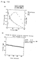
Fig. 13 (a) and (b) are graphic charts showing the
results (current-voltage curve) of a power generation
test at a 10 M methanol concentration, wherein (a) is a
graphic chart of the current-voltage curve, and (b) is a
graphic chart showing the result of continuous power
generation at a constant voltage.
Fig. 14 (a) and (b) are graphic charts showing the
results (current-voltage curve) of a power generation
test of a connected assembly, wherein (a) shows the case
of vertical configuration, and (b) shows the case of
horizontal configuration.
Fig. 15 is a graphic chart of a current density-voltage
curve at the respective methanol solution
concentrations when using Nafion 117 as an electrolyte
membrane.
Fig. 16 is a graphic chart of a current density-voltage
curve at the respective methanol solution
concentrations when using Nafion 112 as an electrolyte
membrane.
Fig. 17 is a schematic drawing showing the form of
a conventional fuel cell in a cross-sectional mode.
Fig. 18 is a schematic drawing showing another form
of a conventional fuel cell in a cross-sectional mode.
DETAILED DESCRIPTION OF THE PREFERRED EMBODIMENTS
The embodiments of the present invention shall be
explained below in details with reference to the drawings.
In the following explanation, air is used as
oxidizing agent gas.
Fig. 1 and Fig. 2 show a fuel cell A showing the
first embodiment of the present invention.
The fuel cell A showing the first embodiment
comprises, as shown in Fig. 1 (a), a base material 10 of
a carbonaceous porous body having electrical conductivity
and has a unit cell (cell of fuel cell) 14 in which the
respective layers (MEA) of electrode 11/electrolyte
12/electrode 13 are formed on the surface of the above
base material 10.
The carbonaceous porous body which is the base
material 10 in the present embodiment has electrical
conductivity and functions (hereinafter referred to
merely as "respective characteristics") as an
impregnating medium for liquid fuel and air and a cell
supporter, and the material thereof shall not
specifically be restricted as long as it has the above
characteristics. It includes, for example, amorphous
carbon, a composite of amorphous carbon and carbon
material powder, an isotropic high density carbon molded
article, a carbon fiber papermaking molded article and an
activated carbon molded article, and the carbonaceous
porous body is preferably constituted from amorphous
carbon or a composite of amorphous carbon and carbon
material powder from the viewpoints of moldability, a
cost and easiness in obtaining the desired physical
properties.
Amorphous carbon is obtained by baking at least one
raw material selected from materials showing a
carbonization yield of 5 % or more by baking, for example,
thermoplastic resins such as polyvinyl chloride,
chlorinated vinyl chloride resins, polyacrylonitrile,
polyvinyl alcohol and vinyl chloride-vinyl acetate
copolymers, thermosetting resins such as phenol resins,
furan resins, imide resins and epoxy resins, and natural
high molecular substances such as cellulose and gum
arabic.
Also, the carbon material powder includes, for
example, at least one selected from the group consisting
of graphite, pitch obtained by subjecting further a tar-like
substance to dry distillation, carbon fibers, carbon
nanotubes and mesocarbon microbeads.
The composite of the amorphous carbon and the
carbon material powder described above is obtained by
mixing 50 to 100 % by weight of an amorphous carbon raw
material having a controlled particle diameter with 0 to
50 % by weight of carbon material powder based on the
total amount and carbonizing the mixture at 700°C or
higher in an inert atmosphere.
In order to preferably exhibit the respective
characteristics described above, the carbonaceous porous
body of the base material 10 has preferably an average
pore diameter of 1 to 100 µm and a porosity of 10 to
85 % and has preferably a liquid-impregnating property by
a capillary phenomenon (function for impregnating liquid
fuel) and strength sufficient for holding a self form.
The carbonaceous porous body has more preferably an
average pore diameter of 5 to 70 µm and a porosity of 20
to 70 % and particularly has preferably a liquid-impregnating
property by a capillary phenomenon.
In the present embodiment (fuel cell A), the
carbonaceous porous body is allowed to have an average
pore diameter of 20 µm and a porosity of 55 % and have a
liquid-impregnating property by a capillary phenomenon
and strength sufficient for holding a self form.
If the average pore diameter(1 to 100 µm) and the
porosity (10 to 85 %) fall outside the ranges described
above, inconvenience is brought about in a certain case
on the electric conductivity and the functions as an
impregnating medium for liquid fuel and air and a cell
supporter, and therefore such ranges are not preferred.
In order to improve the liquid-impregnating
property, the base material obtained may further be
subjected to treatment such as air oxidation and
electrochemical oxidation.
In respect to the carbonaceous porous body having
the respective characteristics described above, for
example, the carbonaceous porous body having the intended
continuous pores can be produced by putting the heat-fusible
resin particles described above in a mold having
an optional form, fusing them with heating and baking
them in an inert atmosphere. Further, the carbonaceous
porous body having the intended continuous pores can be
produced as well by mixing a resin which is a binder with
graphite and the like which is carbon material powder,
crushing and pelletizing the mixture, putting it in a
mold having an optional form and press-molding and baking
it in an inert atmosphere.
The carbonaceous porous body of the base material
10 in the present embodiment assumes, as shown in Fig. 1
(a) and (b), a tabular form and has the respective
characteristics described above in the whole.
In the present invention, the base material 10 may
have electrical conductivity at least in a part, and/or
at least a part thereof may comprise a carbonaceous
porous body.
For example, a part of the base material 10 may be,
as shown in Fig. 1 (c), a non-conductive porous body 10a,
and the other part thereof may be a conductive porous
body 10b. In this case, MEA is formed on the surface of
the conductive porous body 10b.
Also, an upper part and a lower part of the base
material 10 may be, as shown in Fig. 1 (d), the non-conductive
porous body 10a, and the other part thereof
may be the conductive porous body 10b. In this case, MEA
is formed on the surface of the conductive porous body
10b.
Further, a part of the base material 10 may be, as
shown in Fig. 1 (e), a conductive or non-conductive non-porous
body 10c, and the other part thereof may be the
conductive porous body 10b. In this case, MEA is formed
on the surface of the conductive porous body 10b.
The electrode 11 is a fuel electrode prepared by
coating a platinum-ruthenium (Pt-Ru) catalyst, an
iridium-ruthenium (Ir-Ru) catalyst or a platinum-tin (Pt-Sn)
catalyst on one outside surface of the base material
10.
Used for the electrolyte layer 12 is an ion
exchange membrane having a proton conductivity or a
hydroxy ion conductivity, for example, a fluorine base
ion exchange membrane using Nafion 112 and Nafion 117
(all manufactured by Du Pont Co., Ltd.), and in addition
thereto, capable of being used as well are materials
which are excellent in heat resistance and inhibition in
methanol crossover, for example, a composite membrane
comprising an inorganic compound as a proton conductive
material and a polymer as a membrane material, to be
specific, a composite membrane using zeolite as the
inorganic compound and a styrene-butadiene base rubber as
the polymer, and a hydrocarbon base graft membrane.
Also, the electrode 13 is an air electrode prepared
by carrying platinum (Pt), palladium (Pd), rhodium (Rh)
or the like on a sheet-like carbon porous body comprising
a porous structure such as carbon paper by coating.
The unit cell 14 of the present embodiment can be
formed by interposing the electrolyte membrane 12 between
the fuel electrode 11 prepared by coating a Pt-Ru/C
catalyst on the surface of the base material 10 having
the respective characteristics described above and the
air electrode 13 prepared by coating a Pt/C catalyst on
the sheet-like carbon porous body and hot-pressing them.
The unit cell 14 thus obtained stores liquid fuel
and is held by a holder member 20 for holding the above
unit cell.
The holder member 20 has, as shown in Fig. 2 (a)
and (b), a cross-section of a concave form in which one
side is opened, and the inside thereof is a liquid fuel-storing
part 21 for storing liquid fuel 30. The unit
cell 14 is fitted to the inside of the holder member 20
by fitting members 22, 22 so that the air electrode 13 is
situated at an outside surface (atmosphere).
A material for the above holder member 20 shall not
specifically be restricted as long as it has storage
stability and durability to the liquid fuel stored
therein, and it includes, for example, metals such as
stainless steel and synthetic resins such as
polypropylene, polyethylene and polyethylene
terephthalate (PET). An indicated symbol 23 is a fuel-feeding
port having a cover, and indicated symbols 11a,
13a each are a fuel electrode terminal and an air
electrode terminal.
The liquid fuel 30 stored in the liquid fuel-storing
part 21 described above includes a methanol
solution comprising methanol and water, but the liquid
fuel shall not specifically be restricted as long as
hydrogen fed as fuel can be decomposed to hydrogen ion
(H+) and electron (e-) at the fuel electrode 11, and
capable of being used as well are, though depending on
the structure of the fuel electrode 11, for example,
liquid fuels each having a hydrogen source such as
dimethyl ether (DME, CH3OCH3), an ethanol solution,
formic acid, hydrazine and an ammonia solution. The
concentrations of the respective liquid fuels such as DME,
methanol and ethanol are suitably set up.
The methanol solution is preferred from the
viewpoints of a cost, supply capability and high
reactivity, and a concentration thereof is preferably 0.5
to 20 M (mol/L), more preferably 5 to 18 M.
Conventionally, a methanol concentration of 1 to 3 M was
usually regarded as an optimum value, and the performance
was lowered at a higher concentration thereof due to
crossover. In the present invention, however, use of the
base material having the respective characteristics
described above makes it possible to use as well a
methanol solution having a high concentration of 5 M or
more, particularly 10 M or more, which has not been used.
Though the reason therefor has not yet been able to be
clarified, it is presumed that this is due to the facts
that probably the porous base body has the effect of
inhibiting crossover of methanol at the electrolyte
membrane, to be specific, a gas phase of carbon dioxide
which is a reaction product is formed and kept on the
surface of the porous base material brought into contact
with the electrolyte membrane so that crossover of
methanol is inhibited. Use of a methanol solution having
a high concentration raises an energy density of fuel,
and therefore it brings the excellent characteristics
that power is generated for longer time with a smaller
amount of fuel and that a size of a fuel tank is
advantageously reduced. Further, as shown in examples
described later, a solution having a methanol
concentration (17.1 M) which is prepared by mixing 1 mole
of methanol with 1 mole of water can be used as well in
the present invention, and the ideal concentration can
efficiently be used.
In the fuel cell A of the present embodiment thus
constituted, it assumes a structure in which the base
material 10 comprises the carbonaceous porous body having
electrical conductivity and in which the unit cell 14 in
which the respective layers of electrode 11/electrolyte
12/electrode 13 are formed on the surface of the base
material 10 is installed in the holder member 20 to
impregnate the base material 10 with the liquid fuel 30
and further the electrode 13 formed on the outside
surface of the base material 10 is exposed to air. The
base material 10 described above has functions as an
electrode·collector, an impregnating medium for liquid
fuel and air and a cell supporter in common, and the
liquid fuel 30 in the fuel-storing part 21 is introduced
into the cell 14 by an impregnating action to generate
power.
In the present embodiment, as the base material 10
has the characteristic described above, that is,
electrical conductivity and functions as an impregnating
medium for liquid fuel and air and a cell supporter, the
liquid fuel does not leak to the outside, and when the
fuel cell A assumes vertical configuration [Fig. 2 (a)]
or horizontal configuration [Fig. 2 (b)], the liquid fuel
can stably and continuously be fed directly from the
fuel-storing part 21 to the unit cell 14 without stopping.
In the fuel cell A of the above embodiment, the
base material 10 of the carbonaceous porous body having
electrical conductivity is allowed to have functions as
an electrode·collector, an impregnating medium for liquid
fuel and air and a cell supporter in common without using
auxiliary devices such as a pump, a blower, a fuel
vaporizer and a condenser, whereby a separator can be
unnecessary. Accordingly, a structure in which the
liquid fuel can smoothly be fed as it is without
vaporizing is assumed by making use of the above unneeded
space as a field for convecting and diffusing air or
liquid fuel, so that the fuel cell can be reduced in a
size.
Further, in the above embodiment, supplementing of
the liquid fuel from the fuel-feeding port 23 makes it
possible to readily supplement the fuel and stably feed
the liquid fuel.
Further, the embodiment in which one cell 14 is
used has been shown in the present embodiment, and a
prescribed electromotive force (high output) can be
obtained, as described later, by allowing the cell 14 to
assume a connected structure (series or parallel and
combination thereof).
Fig. 3 (a) and (b) show another embodiment of the
cell 14 shown in Fig. 2 and are a perspective drawing and
a partial cross-sectional drawing showing an embodiment
in which the cell is turned into a cartridge form. The
same symbols shall be shown in the case of the same
structure as that of the embodiment described above, and
the explanations thereof shall be omitted (the same shall
apply to embodiments described below). Also, Fig. 3
shows an embodiment in which liquid fuel (fuel solution)
is impregnated from a lower part to an upper part.
The above cell 15 of the fuel cell comprises, as
shown in Fig. 3 (a) and (b), a base material 10 of a
tabular carbonaceous porous body having the respective
characteristics described above and has the respective
layers (MEA) of electrode 11/electrolyte 12/electrode 13
formed on the surfaces (both surfaces) of the base
material 10. An air vent member 17 having air and liquid
holes 16, 16--- for degassing and accelerating
impregnation of liquid fuel is fitted on the upper
surface of the base material 10. The air and liquid
holes may be packed with a water-absorbing material
having a liquid-impregnating characteristic in order to
accelerate impregnation of the liquid fuel. The water-absorbing
material includes, for example, porous bodies
having capillary force which are constituted from felt,
sponge and sintered bodies such as resin particle-sintered
bodies and resin fiber-sintered bodies and fiber
bundles comprising one kind or a combination of two kinds
selected from the group consisting of natural fibers,
animal hair fibers, a polyacetal base resin, an acryl
base resin, a polyester base resin, a polyamide base
resin, a polyurethane base resin, a polyolefin base resin,
a polyvinyl base resin, a polycarbonate base resin, a
polyether base resin and a polyphenylene base resin.
Use of the cell 15 which is turned into a cartridge
form makes it possible to raise an efficiency of joining
work and electrical connection in the cell 15 and to
improve the performances of the fuel cell due to increase
in a convecting and diffusing speed of air or the liquid
fuel brought about by using a space between the cells.
Fig. 4 (a) is a perspective drawing showing an
embodiment in which two cells of the fuel cell are
constituted into one unit, and (b) is a perspective
drawing showing a structure in which a partition wall for
controlling absorption of the liquid fuel and diffusion
of air is provided at an opposite side having no
electrode layer in the cell.
In Fig. 4 (a), the cells 15, 15 in which a cell
layer (electrode/electrolyte/electrode) is formed on one
outside surface of the tabular carbonaceous porous body
having the respective characteristics described above are
disposed back to back at a prescribed interval to form a
gap part 18 for allowing liquid fuel or air to flow and
diffuse between the above cells 15, 15. The cells 15, 15
are electrically connected in a serial or parallel manner.
The gap part 18 makes it possible to improve the
performances of the cell due to increase in a convecting
and diffusing speed of air or the liquid fuel. The gap
part 18 may be packed with the water-absorbing material
described above having a liquid-impregnating
characteristic in order to accelerate impregnation of the
liquid fuel.
Further, one unit is constituted in the form
described above, and it is used alone, or two or more
units which are electrically connected in a serial or
parallel manner are used.
In Fig. 4 (b), the partition wall 19 is provided at
a prescribed interval so that the gap part 18 having the
same function as described above is formed at an opposite
side having no electrode layer in the cell 15. The above
partition wall 19 shall not specifically be restricted as
long as it can cut off fuel or air, and it can be
constituted from, for example, a plastic plate, a metal
plate, a glass plate and a ceramic plate.
Fig. 5 is a perspective drawing showing a structure
in the case where the cells 15, 15 of the fuel cell
turned into a cartridge form in Fig. 3 are serially
connected, and Fig. 6 is a perspective drawing showing a
structure in the case where the cells 15, 15 of the fuel
cell turned into a cartridge form in Fig. 3 are parallel
connected. The fuel cell may have a structure in which a
lot of the cells 15, 15--- turned into a cartridge form
in Fig. 3 are used to combine serial connection shown in
Fig. 5 with parallel connection shown in Fig. 6.
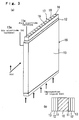
Fig. 7 is a perspective drawing showing a structure
in the case where five cells 15, 15--- turned into a
cartridge form in Fig. 3 are joined and serially
connected. The cells 15, 15--- are preferably fitted so
that intervals between the respective cells are equal via
spacers, or they are preferably fitted at an equal
interval to a holder member which stores the liquid fuel
and holds the cells 15, 15---. Equalizing the intervals
between the respective cells uniformizes flow and a
concentration of air or fuel which convects and diffuses
between the cells to uniformize the outputs of the
respective cells, whereby stabilization in an output of
the cell can be exhibited. The air may suitably be
forcibly convected by means of a small-sized fan in order
to obtain a high output by renewal of the air.
Further, when a connected assembly is formed from
two or more cells 15, 15--- [and when forming the fuel
cell shown in Fig. 4 (a) described above and when forming
the fuel cell in which the partition wall body 19 shown
in Fig. 4 (b) is provided], a thickness of the base
material 10 and an interval between the respective cells
or between the cell and the partition wall body are
varied depending on uses of the fuel cell, a size and a
form of the cell 15, a liquid-absorbing performance of
the base material 10 and liquid fuel used. From the
viewpoint of reduction in a size of the system, H is
preferably 1 to 20 mm, and K is preferably 1 to 20 mm,
wherein H is a thickness of the base material, and K is
an interval between the respective cells or the cell and
the partition wall body.
A width (W) of the base material (including the air
vent member) 10 is varied depending on uses of the fuel
cell, a size and a form of the cell 15, a liquid-absorbing
performance of the base material 10 and liquid
fuel used. It is preferably 1 to 500 mm, and the height
(T) is preferably 5 to 300 mm.
In the above embodiment (fuel cell A), the
thickness H of the base material 10 is 2 mm, and the
interval K is 2 mm; the height T of the base material
(including the air vent member) 10 is 50 mm, and the
width W thereof is 50 mm.
Fig. 8 (a) to (c) are schematic drawings showing a
structure in which the cells of the embodiment shown in
Fig. 7 are fitted to a holder member.
In the above fuel cell B, five cells of the cells
15, 15--- turned into a cartridge form shown in Fig. 3
are fitted, as shown in Fig. 8 (a), to the respective
fitting parts of a liquid fuel tank 31 for storing liquid
fuel 30 and a holder member 32 having an exhaust port for
gas produced, and intervals between the respective cells
described above are set to an equal interval.
The fuel cell B has a structure in which a
carbonaceous porous body in the respective cells 15 is
impregnated with the liquid fuel 30 and in which an
electrode surface formed on the outside surface is
exposed to air, and as shown in Fig. 8 (a) to (c), if a
longitudinal direction of the respective cells is turned
horizontal, vertical or oblique, the respective cells can
be impregnated with the liquid fuel 30 from an upper,
lower or lateral impregnating direction. Accordingly,
the liquid fuel can stably and continuously be fed
directly from the liquid fuel tank 31 to the respective
cells 15 without stopping, and the liquid fuel is
introduced into the respective cells 15 to generate power.
In a fuel cell C shown in Fig. 9, five cells of the
cells 15, 15--- turned into a cartridge form shown in Fig.
3 are disposed in the inside of a liquid fuel tank 33 for
storing liquid fuel 30 and fitted to the respective
fitting parts in air chambers 34, 35 fitted to the upper
and lower parts of the above tank 33, and intervals
between the respective cells described above are set to
an equal interval.
The fuel cell C has a structure in which air is
diffused or convected to the base material of the
respective cells 15, 15--- by means of the air chambers
34, 35 described above and in which an electrode surface
formed on the outside surface of the base material is
exposed to the liquid fuel 30. The liquid fuel can
stably and continuously be fed directly from the liquid
fuel tank 33 to the respective cells 15 without stopping,
and the liquid fuel is introduced into the respective
cells 15 to generate power.
Fig. 10 shows the embodiment of a fuel cell for a
high output (for example, several ten to 100 W).
As shown in Fig. 10, this fuel cell D comprises in
order from a lower part, a fuel tank 40 for storing
liquid fuel 30, an accommodating part 41 for
accommodating a lot of cells 15, 15--- turned into a
cartridge form and a holder 42 having an exhaust port for
gas produced in the liquid fuel. The cells 15, 15---
described above are fitted to the respective fitting
parts of the fuel tank 40 for storing the liquid fuel 30
and the holder 42, and intervals between the respective
cells are set to an equal interval. The peripheral
surface of the accomodating part 41 is constituted from
an air flow member 43 through which air is easy to pass,
for example, a net, a slit and the like. The respective
cells 15, 15--- are serially connected, and an indicated
symbol 44 is a terminal of an electric source.
The fuel cell D has a structure in which a
carbonaceous porous body in the respective cells 15 is
impregnated with the liquid fuel 30 and in which an
electrode surface formed on the outside surface is
exposed to air. The liquid fuel can stably and
continuously be fed directly from the liquid fuel tank 40
to the respective cells 15 without stopping, and the
liquid fuel is introduced into the respective cells 15 to
generate power. Air may be blown by means of a fan from
the viewpoint of further increase in the output.
Fig. 11 (a) to (c) are schematic drawings showing a
fuel cell of an embodiment which is accommodated in
small-sized appliances such as writing instruments,
celluar phones and note type personal computers, and it
is a fuel cell E in which a cylindrical cell of the fuel
cell is used.
The above fuel cell E is different from the fuel
cell D described above in that it is cylindrical in an
appearance form. It comprises in order from a lower part,
as shown in Fig. 11 (a), a fuel tank 45 for storing
liquid fuel 30, an accommodating part 46 for
accommodating a lot (6 cells in the present embodiment)
of cylindrical cells 16, 16--- and a holder 47 having an
exhaust port for gas produced in the liquid fuel. The
cells 16, 16--- are fitted to the respective fitting
parts of the fuel tank 45 for storing the liquid fuel 30
and the holder 47, and intervals between the respective
cells are set to an equal interval. The peripheral
surface of the accommodating part 46 is constituted from
an air flow member 48 through which air is easy to pass,
for example, a net, a slit and the like. The respective
cells 16, 16--- are electrically connected in a serial or
parallel manner, whereby they can readily be stacked. An
indicated symbol 49 is a terminal of an electric source.
As shown in Fig. 11 (b) and (c), the respective
cells 16, 16--- have a structure in which a through hole
16a for degassing and accelerating impregnation of the
liquid fuel is formed in a central part and in which the
respective layers of electrode 11/electrolyte
12/electrode 13 are formed on the outside surface of a
cylindrical porous carbon base material 10.
The fuel cell E has a structure in which a
carbonaceous porous body in the respective cells 16 is
impregnated with the liquid fuel 30 and in which an
electrode surface formed on the outside surface is
exposed to air. A cylindrical solid space can
effectively used, and a separator is unneeded. In
addition thereto, a space in which an air electrode on
the outside surface can sufficiently be brought into
contact with air can be secured. The liquid fuel can
stably and continuously be fed directly from the liquid
fuel tank 44 to the respective cells 16 without stopping,
and the liquid fuel is introduced into the respective
cylindrical cells 16 to generate power.
The fuel cells of the present invention have the
structures described above and exhibits the respective
actions and effects, but the present invention shall not
be restricted to the embodiments described above and can
be carried out in various embodiments as long as the
scope of the present invention is not changed.
For example, it has been described in the
embodiments described above that the carbonaceous porous
body which is the base material described above has a
tabular or cylindrical form, but it may have a prismatic,
circular cylindrical, square cylindrical or corrugated
sheet form.
Further, a part of the carbonaceous porous body may
be non-conductive and non-porous.
Examples
Next, the present invention shall be explained in
further details with reference to examples, but the
present invention shall not be restricted to the examples
described below.
Example 1
A carbonaceous porous body having the following
structure produced by the following production process
was used for a base material.
Production of carbonaceous porous body:
Chlorinated vinyl chloride resin powder 97 parts
prepared by classifying chlorinated vinyl chloride resin
powder (T-741, manufactured by Nippon Carbide Industries
Co., Inc.) in a range of 50 to 300 µm was mixed well
with natural scaly graphite (average particle diameter: 5
µm, manufactured by Nippon Graphite Industries, Ltd.) by
means of a Henschel mixer, and the mixture was put into a
mold having a length of 100 mm, a width of 100 mm and a
depth of 5 mm. Then, it was baked up to 1000°C under an
inert atmosphere, whereby the powder particles were fused
to obtain a carbonaceous porous body (average particle
diameter: 20 µm, porosity: 55 %) having continuous pores.
The carbonaceous porous body thus obtained was
processed to obtain a carbonaceous porous body having a
width of 25 mm, a length of 65 mm and a thickness of 2 mm.
Preparation of cell (MEA)
The resulting carbonaceous porous body described
above having a width of 25 mm, a length of 65 mm and a
thickness of 2 mm was used as a base material 10.
Catalyst powder obtained by dispersing and carrying
platinum/ruthenium fine particles having a
platinum/ruthenium ratio of 1 : 1 (atomic ratio) on a
carbon fine particle carrier in a proportion of 65 wt %,
water, glycerol, a 5 wt % solution of Nafion 117 in an
alcohol aqueous solution (manufactured by Wako Pure
Chemical Industries, Ltd.) and isopropyl alcohol were
mixed in a ratio of 1 : 1 : 3 : 3 : 3 in terms of weight
ratio to prepare a slurry, and the slurry thus obtained
was coated on the surface of the base material in a
thickness of about 50 µm by a slurry coating method and
dried to form a porous membrane, whereby a fuel electrode
11 was prepared.
A slurry comprising a mixture of catalyst powder
obtained by carrying platinum fine particles on a carbon
fine particle carrier in a proportion of 50 wt %, water,
glycerol and a solution of Nafion in an alcohol aqueous
solution was coated on the surface of carbon paper
subjected to water repellent treatment in a thickness of
about 50 µm and dried to form a porous membrane. This
was cut to a width of 25 mm and a length of 65 mm to
prepare an air electrode 13.
Further, a Nafion 112 electrolyte membrane having a
thickness of 50 µm was cut to a width of 25 mm and a
length of 100 mm to prepare an electrolyte membrane 12.
A small amount of the 5 wt % solution of Nafion 117
in alcohol was coated on the surface of the fuel
electrode layer and the air electrode layer and dried,
and then the electrolyte membrane was interposed between
the fuel electrode layer and the air electrode layer so
that the respective electrode layers were superposed each
other, and the laminate was pressed at 130°C and about 80
kgf/cm2 and held for 3 minutes to stick them, whereby a
cell (MEA) was prepared.
The above cell was used to obtain a fuel cell based
on Fig. 2 (a) and (b).
A methanol aqueous solution (methanol
concentration: 2 M and 10 M (M = mol/L)) 20 ml was used
as liquid fuel.
A power generation test (current-voltage curve) was
carried out respectively for the case where the above
fuel cell assumed a vertical configuration [refer to Fig.
2 (a)] in which only a lower part of the base material of
the carbonaceous porous body is brought into contact with
the methanol aqueous solution to self-impregnate the base
material with the methanol aqueous solution and the case
where the fuel cell assumed a horizontal configuration
[refer to Fig. 2 (b)] to impregnate the base material
with the methanol aqueous solution. The air electrode
was exposed to air at room temperature (25°C) and an
atmospheric pressure without flow.
The results thereof (current-voltage curve) are
shown in Fig. 12 and Fig. 13.
As apparent from the result obtained in the case of
the vertical configuration shown in Fig. 12 (a) and the
result obtained in the case of the horizontal
configuration shown in Fig. 12 (b), it has become clear
that current can be output from a single cell in a
voltage range up to about 0.5 V to obtain a maximum
output exceeding 10 mW and that the respective fuel cells
work well.
Further, Fig. 13 (a) shows a current-voltage curve
in the case where a methanol concentration is 10 M, and
(b) shows the result of continuous power generation at a
fixed voltage (0.1 V). It has become clear that almost
the same output as the case of 2 M is obtained as well in
the case of 10 M and that the fuel cells work so well
that the same power generation characteristic is obtained
in a wide concentration range. Further, it has become
clear that the voltage does not fall to a large extent in
the case of continuous power generation for 8 hours or
longer to stably output current and that the fuel cells
can stably work well.
Cell-connected assembly
Two cells obtained above were used to obtain
parallel connected and serially connected fuel cells
having a cell interval of 10 mm based on Fig. 2 (a) and
(b) and Fig. 4 (a).
The power generation test (current-voltage curve)
was carried out for the fuel cells thus obtained in the
same manner as described above.
The results thereof (current-voltage curve) are
shown in Fig. 14 (a) and (b).
Fig. 14 (a) shows a current-voltage curve in the
case of parallel connection, and (b) shows a current-voltage
curve in the case of serial connection. A
current value which is almost twice as large as that of
the unit cell is obtained in the parallel connection, and
voltage which is as almost twice as large as that of the
unit cell is obtained in the serial connection. It has
become clear that the fuel cells work well in the case of
the connected assembly too.
Example 2
A carbonaceous porous body having the following
structure produced by the following production process
was used for a base material.
Production of carbonaceous porous body:
Dry-distilled pitch (KH-IP, manufactured by Kureha
Chemical Industry Co., Ltd.) 15 parts, a furan resin
(VF303, manufactured by Hitachi Chemical Co., Ltd.) 35
parts, polymethyl methacrylate (average particle
diameter: 60 µm, manufactured by Sekisui Plastics Co.,
Ltd.) 35 parts and natural scaly graphite (average
particle diameter: 5 µm, manufactured by Nippon Graphite
Industries, Ltd.) 15 parts were classified, mixed and
kneaded, and thereafter the mixture was crushed,
classified and then put into a mold having a length of
100 mm, a width of 100 mm and a depth of 5 mm. Then, it
was subjected to compression molding to obtain a
carbonaceous porous body (average particle diameter: 60
µm, porosity: 60 %) having continuous pores.
The carbonaceous porous body thus obtained was
processed to obtain a carbonaceous porous body having a
width of 25 mm, a length of 65 mm and a thickness of 2 mm.
Preparation of cell (MEA)
The respective cells (MEA) were prepared in the
same manner as that of the cells (MEA) prepared in
Example 1 described above, provided that two kinds of
Nafion 112 and 117 membranes having a thickness of 50 µm
were used for the electrolyte membrane 12.
The above cells were used to obtain a fuel cell
based on Fig. 2 (b).
A methanol aqueous solution (methanol
concentration: 2 M, 5 M, 10 M, 12 M, 15 M, 17 M and 20 M
(M = mol/L)) 20 ml was used as liquid fuel.
A power generation test (current density-voltage
curve) was carried out for the case where the above fuel
cell assumed a horizontal configuration [Fig. 2 (b)] to
impregnate the base material with the methanol aqueous
solution. The air electrode was exposed to air at room
temperature (15 to 18°C, 18°C to 20°C) and an atmospheric
pressure without flow.
The results thereof (current density-voltage curve)
are shown in Fig. 15 and the following Table 1 (Nafion
117 was used) and Fig. 16 and the following Table 2
(
Nafion 112 was used).
| Respective numeral value tables of current density-voltage in the respective methanol concentrations when using Nafion 117 for the electrolyte membrane |
| (1) 2 M methanol concentration |
| Current density (mA/cm2) | Voltage (V) |
| 0.00000 | 0.4982 |
| 0.055172 | 0.4511 |
| 0.22069 | 0.4010 |
| 0.78621 | 0.3504 |
| 1.4345 | 0.3000 |
| 2.9931 | 0.2500 |
| 4.8759 | 0.2003 |
| 7.7897 | 0.1495 |
| 11.759 | 0.0995 |
| 16.145 | 0.0507 |
| 21.386 | 0.0050 |
| (2) 5 M methanol concentration |
| Current density (mA/cm2) | Voltage (V) |
| 0.00000 | 0.4934 |
| 0.15862 | 0.4480 |
| 0.18621 | 0.3980 |
| 0.50345 | 0.3509 |
| 1.1793 | 0.2980 |
| 3.2000 | 0.2487 |
| 5.5448 | 0.2009 |
| 8.6621 | 0.1506 |
| 12.934 | 0.0984 |
| 17.710 | 0.0505 |
| 22.924 | 0.0000 |
| (3) 10 M methanol concentration |
| Current density (mA/cm2) | Voltage (V) |
| 0.00000 | 0.4783 |
| 0.048276 | 0.4494 |
| 0.22069 | 0.4002 |
| 0.60690 | 0.3504 |
| 1.2062 | 0.3003 |
| 2.5414 | 0.2500 |
| 4.6931 | 0.1990 |
| 7.7069 | 0.1500 |
| 11.566 | 0.1001 |
| 15.772 | 0.0510 |
| 20.914 | 0.0020 |
| (4) 15 M methanol concentration |
| Current density (mA/cm2) | Voltage (V) |
| 0.00000 | 0.4320 |
| 0.11724 | 0.3965 |
| 0.13103 | 0.3500 |
| 1.8483 | 0.3000 |
| 2.3448 | 0.2500 |
| 5.1310 | 0.2000 |
| 8.8000 | 0.1490 |
| 12.910 | 0.1000 |
| 17.297 | 0.0510 |
| 22.814 | 0.0007 |
| (5) 20 M methanol concentration |
| Current density (mA/cm2) | Voltage (V) |
| 0.00000 | 0.4422 |
| 0.20690 | 0.4064 |
| 0.27586 | 0.3495 |
| 1.5083 | 0.3013 |
| 1.5731 | 0.2503 |
| 2.5172 | 0.2000 |
| 4.5172 | 0.1498 |
| 7.0276 | 0.1003 |
| 10.186 | 0.0500 |
| 13.690 | 0.0004 |
| Respective numeral value tables of current density-voltage in the respective methanol concentrations when using Nafion 112 for the electrolyte membrane |
| (1) 5 M methanol concentration |
| Current density (mA/cm2) | Voltage (V) |
| 0.00000 | 0.4573 |
| 0.27259 | 0.4014 |
| 0.33185 | 0.3521 |
| 0.71111 | 0.3012 |
| 1.2661 | 0.2499 |
| 2.1333 | 0.2016 |
| 4.0296 | 0.1499 |
| 6.1156 | 0.0999 |
| 8.3793 | 0.0500 |
| 11.970 | 0.0014 |
| (2) 10 M methanol concentration |
| Current density (mA/cm2) | Voltage (V) |
| 0.00000 | 0.4764 |
| 0.077037 | 0.4475 |
| 0.074074 | 0.3987 |
| 0.56000 | 0.3503 |
| 0.93037 | 0.3000 |
| 1.4044 | 0.2511 |
| 2.7881 | 0.2001 |
| 4.4000 | 0.1487 |
| 6.5600 | 0.1000 |
| 9.2385 | 0.0510 |
| 13.138 | 0.0010 |
| (3) 12 M methanol concentration |
| Current density (mA/cm2) | Voltage (V) |
| 0.0000 | 0.4622 |
| 0.28444 | 0.4220 |
| 0.35259 | 0.3984 |
| 0.45037 | 0.3499 |
| 1.2089 | 0.2985 |
| 1.9200 | 0.2492 |
| 3.4252 | 0.2006 |
| 5.5230 | 0.1483 |
| 7.8222 | 0.1005 |
| 11.150 | 0.0485 |
| 15.013 | 0.0020 |
| (4) 15 M methanol concentration |
| Current density (mA/cm2) | Voltage (V) |
| 0.00000 | 0.4307 |
| 0.094815 | 0.4005 |
| 0.23704 | 0.3508 |
| 0.85333 | 0.3007 |
| 1.6358 | 0.2495 |
| 3.4104 | 0.1999 |
| 5.3096 | 0.1498 |
| 8.2489 | 0.1002 |
| 11.236 | 0.0502 |
| 15.876 | 0.0024 |
| (5) 17 M methanol concentration |
| Current density (mA/cm2) | Voltage (V) |
| 0.00000 | 0.4350 |
| 0.20148 | 0.4017 |
| 0.42687 | 0.3508 |
| 1.0667 | 0.3004 |
| 1.7422 | 0.2503 |
| 3.4074 | 0.1996 |
| 5.6830 | 0.1503 |
| 8.2252 | 0.0989 |
| 11.336 | 0.0499 |
| 15.858 | 0.0040 |
| (6) 20 M methanol concentration |
| Current density (mA/cm2) | Voltage (V) |
| 0.0000 | 0.4445 |
| 0.38815 | 0.3980 |
| 0.53037 | 0.3498 |
| 0.85926 | 0.3063 |
| 1.3037 | 0.2493 |
| 2.7141 | 0.2011 |
| 4.3141 | 0.1502 |
| 7.2296 | 0.1002 |
| 10.453 | 0.5040 |
| 14.009 | 0.0080 |
As apparent from the results shown in Fig. 15
(Table 1) and Fig. 16 (Table 2), the optimum values are
shown at the methanol concentrations of 15M to 17M
(mol/L). In the reaction of methanol with water at the
electrode, 1 mole of water is theoretically used for 1
mole of methanol. Usually, a solution obtained by mixing
1 mole of methanol with 1 mole of water has a
concentration of 17.1 M, and therefore it has become
clear that the almost ideal concentration can be used in
the present invention.
Conventionally, the optimum value was usually shown
at a methanol concentration of 1 to 3 M, and the
performance was reduced at a higher concentration due to
crossover of methanol. In the present invention, however,
use of the base material having the characteristics
described above makes it possible to make use of a
methanol solution having a high concentration. As a
result, an energy density of fuel per volume is raised,
and therefore it is most suited for further reduction in
a size of the appliances.