EP1562014A1 - Stacking-type, multi-flow, heat exchanger - Google Patents
Stacking-type, multi-flow, heat exchanger Download PDFInfo
- Publication number
- EP1562014A1 EP1562014A1 EP05250255A EP05250255A EP1562014A1 EP 1562014 A1 EP1562014 A1 EP 1562014A1 EP 05250255 A EP05250255 A EP 05250255A EP 05250255 A EP05250255 A EP 05250255A EP 1562014 A1 EP1562014 A1 EP 1562014A1
- Authority
- EP
- European Patent Office
- Prior art keywords
- heat exchanger
- end plate
- closing
- forming
- plate
- Prior art date
- Legal status (The legal status is an assumption and is not a legal conclusion. Google has not performed a legal analysis and makes no representation as to the accuracy of the status listed.)
- Granted
Links
Images


Classifications
-
- F—MECHANICAL ENGINEERING; LIGHTING; HEATING; WEAPONS; BLASTING
- F28—HEAT EXCHANGE IN GENERAL
- F28F—DETAILS OF HEAT-EXCHANGE AND HEAT-TRANSFER APPARATUS, OF GENERAL APPLICATION
- F28F9/00—Casings; Header boxes; Auxiliary supports for elements; Auxiliary members within casings
- F28F9/02—Header boxes; End plates
- F28F9/0202—Header boxes having their inner space divided by partitions
-
- F—MECHANICAL ENGINEERING; LIGHTING; HEATING; WEAPONS; BLASTING
- F28—HEAT EXCHANGE IN GENERAL
- F28D—HEAT-EXCHANGE APPARATUS, NOT PROVIDED FOR IN ANOTHER SUBCLASS, IN WHICH THE HEAT-EXCHANGE MEDIA DO NOT COME INTO DIRECT CONTACT
- F28D1/00—Heat-exchange apparatus having stationary conduit assemblies for one heat-exchange medium only, the media being in contact with different sides of the conduit wall, in which the other heat-exchange medium is a large body of fluid, e.g. domestic or motor car radiators
- F28D1/02—Heat-exchange apparatus having stationary conduit assemblies for one heat-exchange medium only, the media being in contact with different sides of the conduit wall, in which the other heat-exchange medium is a large body of fluid, e.g. domestic or motor car radiators with heat-exchange conduits immersed in the body of fluid
- F28D1/03—Heat-exchange apparatus having stationary conduit assemblies for one heat-exchange medium only, the media being in contact with different sides of the conduit wall, in which the other heat-exchange medium is a large body of fluid, e.g. domestic or motor car radiators with heat-exchange conduits immersed in the body of fluid with plate-like or laminated conduits
- F28D1/0308—Heat-exchange apparatus having stationary conduit assemblies for one heat-exchange medium only, the media being in contact with different sides of the conduit wall, in which the other heat-exchange medium is a large body of fluid, e.g. domestic or motor car radiators with heat-exchange conduits immersed in the body of fluid with plate-like or laminated conduits the conduits being formed by paired plates touching each other
- F28D1/0325—Heat-exchange apparatus having stationary conduit assemblies for one heat-exchange medium only, the media being in contact with different sides of the conduit wall, in which the other heat-exchange medium is a large body of fluid, e.g. domestic or motor car radiators with heat-exchange conduits immersed in the body of fluid with plate-like or laminated conduits the conduits being formed by paired plates touching each other the plates having lateral openings therein for circulation of the heat-exchange medium from one conduit to another
- F28D1/0333—Heat-exchange apparatus having stationary conduit assemblies for one heat-exchange medium only, the media being in contact with different sides of the conduit wall, in which the other heat-exchange medium is a large body of fluid, e.g. domestic or motor car radiators with heat-exchange conduits immersed in the body of fluid with plate-like or laminated conduits the conduits being formed by paired plates touching each other the plates having lateral openings therein for circulation of the heat-exchange medium from one conduit to another the plates having integrated connecting members
-
- F—MECHANICAL ENGINEERING; LIGHTING; HEATING; WEAPONS; BLASTING
- F28—HEAT EXCHANGE IN GENERAL
- F28F—DETAILS OF HEAT-EXCHANGE AND HEAT-TRANSFER APPARATUS, OF GENERAL APPLICATION
- F28F2280/00—Mounting arrangements; Arrangements for facilitating assembling or disassembling of heat exchanger parts
- F28F2280/04—Means for preventing wrong assembling of parts
-
- Y—GENERAL TAGGING OF NEW TECHNOLOGICAL DEVELOPMENTS; GENERAL TAGGING OF CROSS-SECTIONAL TECHNOLOGIES SPANNING OVER SEVERAL SECTIONS OF THE IPC; TECHNICAL SUBJECTS COVERED BY FORMER USPC CROSS-REFERENCE ART COLLECTIONS [XRACs] AND DIGESTS
- Y10—TECHNICAL SUBJECTS COVERED BY FORMER USPC
- Y10T—TECHNICAL SUBJECTS COVERED BY FORMER US CLASSIFICATION
- Y10T29/00—Metal working
- Y10T29/49—Method of mechanical manufacture
- Y10T29/4935—Heat exchanger or boiler making
- Y10T29/49389—Header or manifold making
Definitions
- the present invention relates to a stacking-type, multi-flow, heat exchanger comprising an end plate connected to an outermost layer of a heat exchanger core formed by stacking heat transfer tubes and fins alternately, and to methods for manufacturing such heat exchangers.
- the present invention relates to an improved structure of a stacking-type, multi-flow, heat exchanger suitable as a heat exchanger for use in an air conditioner, in particular, for vehicles.
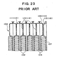
- a stacking-type, multi-flow, heat exchanger having alternately stacked heat transfer tubes and fins is known in the art, for example, as a heat exchanger having a structure shown in Figs. 22 and 23 (as shown in Japanese Utility Model Laid-Open No. 7-12778).
- a heat exchanger 101 has a heat exchanger core 104 formed by heat transfer tubes 102 and fins 103 i.e., (outer fins) stacked alternately.
- a side tank 105 is provided on one end of heat exchanger core 104 in the stacking direction, for forming introduction/discharge passages of a heat exchange medium (e.g., refrigerant), and a flange 106 connected with an expansion valve (not shown) is connected to side tank 105.
- a heat exchange medium e.g., refrigerant
- a flange 106 connected with an expansion valve (not shown) is connected to side tank 105.
- an end plate 107 is provided on the other end of heat exchanger core 104.
- Each heat transfer tube 102 is formed by connecting ( e.g. , brazing) a pair of tube plates 108, which have the same configuration, to each other.
- Projecting portions 109 and 110 are provided on both ends of each tube plate 108 for forming tanks 111 and 112 at the upper and lower portions of heat exchanger core 104.
- Communication holes 113 and 114 for a heat exchange medium are formed through projecting portions 109 and 110.
- heat transfer tube 102 To form heat transfer tube 102, a pair of tube plates 108 are connected to each other, so that the respective projecting portions 109 and 110 are set at opposite sides, and projecting portions 109 and projecting portions 110 of a plurality of heat transfer tubes 102 are connected to each other, respectively, to form tanks 111 and 112 at either end of heat exchanger core 104. Communication holes 113 and 114 of outermost tube plate 108 at the end plate side are closed by projecting portions 115 and 116 of end plate 107, respectively.
- Heat exchanger 101 may be manufactured by temporarily assembling the respective members, and brazing the assembly at a later time in a furnace, wherein the assembly is held from both sides of heat exchanger 101 in the stacking direction by a brazing jig (not shown).
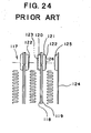
- each heat transfer tube 117 is formed by a first tube plate 118 and a second tube plate 119.
- a raised portion 122 is formed by creating a lip or edge on a projecting portion 121 for forming a tank of second tube plate 119, and raised portion 122 is inserted into a communication hole 123 formed through a projecting portion 120 of first tube plate 118 to prevent a positional shift at the time of the assembly.
- An opening 126 of raised portion 122 of outermost tube plate 119 is closed by a projecting portion 125 of an end plate 124.
- stacking-type, multi-flow, heat exchangers and especially, high-performance, stacking-type, multi-flow, heat exchangers, which may achieve a high degree of accuracy in the assembly of an end plate and various parts, and which may achieve a desirable connection of respective parts with both a high degree of accuracy in position and sufficient bonding strength, at a low cost.
- a stacking-type, multi-flow, heat exchanger comprises a heat exchanger core comprising a plurality of heat transfer tubes each formed by connecting a pair of tube plates to each other and a plurality of fins, which are stacked alternately, and a tank portion formed at least at an end of the plurality of heat transfer tubes, and an end plate connected to an outermost tube plate of the heat exchanger core.
- the heat exchanger comprises a projecting portion provided on a surface of the outermost tube plate at least at an end portion of the outermost tube plate for forming a part of the tank, a raised portion with an opening formed on the projecting portion, and an engaging portion and a closing portion provided to the end plate for engaging the raised portion and for closing the opening of the raised portion.
- the engaging portion which engages the raised portion of the outermost tube plate, is provided integrally to the end plate
- the end plate may be readily positioned relative to the outermost tube plate with a high degree of accuracy, and may be temporarily secured surely for a proper assembly. Therefore, because a positional shift of the end plate during the temporary assembly may be reduced or prevented, the brazing properties (e.g ., the brazing accuracy) of the end plate and, ultimately, of the respective parts, may be enhanced.
- Such an engaging function may be readily achieved by a combination of the raised portion and a hole provided on the end plate engaging the raised portion.
- the closing portion which closes the opening of the raised portion
- the opening of the raised portion may be closed readily and certainly by setting the end plate.
- the periphery of the raised portion and the inner circumferential edge of the hole of the end plate and the end surface of the raised portion and the end plate may be more securely brazed, the brazing area between the end plate and the outermost tube plate may be enlarged, and the strength of the braze between both members may be increased.
- Such a closing function may be readily achieved by providing a lid to the end plate for closing the opening of the raised portion.
- Such a lid may be formed integrally with the end plate.
- an opening inserted with the raised portion is provided to the end plate, an extended portion is formed on an end of the end plate, and by turning back the extended portion to close the opening of the raised portion, the above-described lid, having the closing function, may be readily formed.
- the above-described end plate having the hole for engaging the raised portion and the extended portion for forming the lid closing the opening of the raised portion, may be readily manufactured by a single process, such as pressing, stamping, or the like. Therefore, in the present invention, the number of parts and the number of processes, may not be increased substantially, and the cost for the manufacture may be reduced or prevented for rising.
- the lid is formed to have a portion protruded from a position of the raised portion, the strength of the lid may be increased. Further, if the degree of protrusion of the protruded portion is set, so that an outer surface of the protruded portion and an outer surface of a portion of the end plate connected to an outermost fin are formed to be substantially flush, the temporarily assembled heat exchanger may be securely fixed by using a simple jig for brazing. Therefore, the brazing property may be significantly improved.
- the engaging portion and the closing portion are provided integrally to the end plate for engaging the raised portion of the outermost tube plate and for closing the opening of the raised portion (i.e., for closing an end of a tank), the end plate and, ultimately, the entire heat exchanger, may be assembled temporarily at a proper position with a high degree of accuracy, and the brazing properties may be significantly improved. Further, by providing the closing portion integrally to the end plate, increases in the number of the parts and the number of processes may be substantially prevented. This may contribute to lowering costs or reducing or eliminating cost increases.
- a method for manufacturing a stacking-type, multi-flow, heat exchanger in which the heat exchanger may comprise a heat exchanger core comprising a plurality of heat transfer tubes, is provided.
- the method comprises the steps of: forming the heat exchanger tubes by connecting a pair of tube plates to each other; stacking the plurality of tubes alternatively with a plurality of fins to form said core; and forming a tank portion at least at an end of the core by connecting an end plate to an outermost tube plate of the core.
- the tank portion is formed by providing a projecting portion on a surface of said outermost tube plate at least at an end portion of the outermost tube plate for forming a part of the tank, surrounding an opening formed through the projecting portion with a raised portion, and providing an engaging portion and a closing portion to the end plate for engaging the raised portion and for closing the opening of the raised portion.
- Heat exchanger 1 is constructed as a stacking-type, multi-flow, heat exchanger.
- heat exchanger 1 comprises a heat exchanger core 4 formed by a plurality of heat transfer tubes 2 and a plurality of outer fins 3 stacked alternately.
- a side tank 5 is connected to one end of heat exchanger core 4 in the stacking direction, and introduction/discharge passages of a heat exchange medium (e.g. , refrigerant) into/from the heat exchanger are formed in the side tank 5.
- a flange 8 having an inlet 6 and an outlet 7 for heat exchange medium is connected to side tank 5.
- An end plate 9 is connected to the other end of heat exchanger core 4 in the stacking direction.
- each heat transfer tube 2 is formed by connecting a pair of tube plates 10 and 11 (i.e., a first tube plate 10 and a second tube plate 11) to each other at their outer circumferential portions.
- Projecting portions 12, 13, 14, and 15 projecting outwardly for forming tanks 30, 31, 32, and 33 are provided in first tube plate 10.
- Passage forming portions 16 and 17 extending along the longitudinal direction of first tube plate 10 are formed in first tube plate 10.
- projecting portions 18, 19, 20, and 21 projecting outwardly for forming tanks 30, 31, 32, and 33 are provided in second tube plate 11.
- Passage forming portions 22 and 23 extending along the longitudinal direction of second tube plate 11 are formed in second tube plate 11.
- raised portions 24, 25, 26, and 27 formed by stamping or the like are provided to projecting portions 18, 19, 20, and 21.
- inner passages for heat exchange medium 28 and 29 are formed between passage forming portions 16 and 22 and between passage forming portions 17 and 23 by connecting tube plates 10 and 11 to each other.
- An inner fin (not shown) may be inserted into each of passages 28 and 29.
- heat transfer tubes 2 When heat transfer tubes 2 are stacked, raised portions 24, 25, 26, and 27 provided on projecting portions 18, 19, 20, and 21 of second tube plates 11 are inserted into communication holes 34, 35, 36, and 37 formed through corresponding projecting portions 12, 13, 14, and 15 of first tube plates 10. Therefore, the whole of heat exchanger core 4 including the respective tanks may be assembled temporarily without any positional shift.
- Raised portions 24, 25, 26, and 27 of second tube plate 11 of an outermost heat transfer tube 2 are inserted into holes 38, 39, 40, and 41 formed through end plate 9.
- an engaging portion 48 is formed by inserting the respective raised portions into each of the corresponding holes of end plate 9.
- Openings 42 and 43 of raised portions 24 and 25 at one end of second tube plate 11 of the outermost, heat transfer tube 2 are closed by a lid 44 formed integrally with end plate 9. Openings 45 and 46 of raised portions 26 and 27 at the other end of second tube plate 11 of the outermost heat transfer tube 2 are closed by a lid 47 formed integrally with end plate 9. As depicted in Fig. 6, these lids 44 and 47 are formed by turning back extended portions 44a and 47a, formed integrally with end plate 9, at a position of the respective dashed lines of Fig. 6. By this turning-back process, openings 42, 43, 45, and 46 of raised portions 24, 25, 26, and 27 are closed by lids 44 and 47, as depicted in Fig. 7. These lids 44 and 47 form closing portions 49 for closing openings 42, 43, 45, and 46 of raised portions 24, 25, 26, and 27 of the outermost, heat transfer tube 2.
- engaging portions 48 and closing portions 49 are formed integrally with end plate 9.
- End plate 9 having the above-described holes 38, 39, 40 and 41 forming engaging portions 48 and lids 44 and 47 (i.e., extended portions 44a and 47a) forming closing portions 49 may be formed by a single process, such as pressing, stamping, or the like. Therefore, increases in the number of the parts and the number of the manufacturing method steps may be substantially prevented, and the cost for the manufacture may be effectively reduced or prevented from rising.
- heat exchanger 1 In heat exchanger 1 described above, the respective parts are assembled temporarily, and the assembly is brazed at a later time in a furnace. Therefore, if the positional relationship between the respective parts is not properly set, the brazing properties may be markedly reduced.
- an end plate In a known, stacking-type, multi-flow, heat exchanger, although an end plate is precisely positioned during assembly, it is difficult to maintain this positioning during brazing. Further, because the brazing area between an end plate and an outermost, tube plate .(eg, an outermost second tube plate) is limited, it is difficult to ensure a sufficient connection strength of this portion.
- engaging portion 48 and closing portion 49 are provided integrally to end plate 9.
- the end plate 9 may be accurately positioned relative to the outermost, second tube plate 11 of the outermost, heat transfer tube 2. Therefore, when temporarily assembled, a positional shift of end plate 9 may be reduced or prevented, end plate 9 and, ultimately, the entire heat exchanger 1 including other parts, may be maintained in position even during brazing, and the brazing properties may be significantly improved.
- lids 44 and 47 functioning as closing portions for closing openings 42, 43, 45, and 46 of respective raised portions 24, 25, 26, and 27 are provided integrally to end plate 9. Therefore, by forming extended portions 44a and 47a by pressing, stamping, or the like and turning back the extended portions 44a and 47a to engage outermost, second tube plate 11 and form lids 44 and 47, the openings 42, 43, 45, and 46 of respective raised portions 24, 25, 26, and 27 may be closed readily and securely.
- each of heat transfer tubes 2 may be formed from a pair of the same tube plates 11.
- heat transfer tube 2 may be formed by connecting a tube plate 11 to another tube plate 11 having substantially the same structure, but reversed, in the vertical direction.
- the object of the present invention may be achieved by forming a raised portion on at least one projecting portion.
- outer surfaces 50 and 51 of lids 44 and 47 are not flush relative to outer surface 52 of a portion of end plate 9 connected to outermost, outer fin 3 in the above-described embodiment, as depicted in Fig. 10. Nevertheless, by forming portions 54 and 55 of a brazing jig 53 to be brought into contact with outer surfaces 50 and 51 of lids 44 and 47 as thicker portions, the securing function by brazing jig 53 may be exhibited more properly, and during brazing in a furnace, a positional shift of the parts of heat exchanger 1 assembled temporarily may be reduced or prevented.
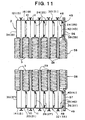
- Fig. 11 depicts a stacking-type, multi-flow, heat exchanger, according to a second embodiment of the present invention.
- the explanation of the same members as those described with respect to first embodiment is omitted by providing the same reference numerals as those in the first embodiment.
- lids 56 and 57 closing openings 42, 43, 45, and 46 of raised portions 24, 25, 26, and 27 are formed separately from end plate 58.
- end plate 58 may be positioned with certainty and assembled with a high degree of accuracy, and the brazing properties and the pressure resistance may be increased.
- lids 56 and 57 as thick members, outer surfaces 59 and 60 of the lids 56 and 57 may be substantially flush relative to outer surface 61 of a portion of end plate 58, which is connected to the outermost fin. Therefore, it is not necessary to provide thicker portions 54 and 55 to brazing jig 53 as in the first embodiment, and the structure of the brazing jig 53 may be simplified and the fixing strength thereof may be increased. Moreover, by forming lids 56 and 57 as thicker members, the pressure resistance of the portions provided therewith may be further increased.
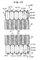
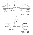
- Figs. 13 to 16 depict a stacking-type, multi-flow, heat exchanger and the method for manufacturing such a heat exchanger, according to a third embodiment of the present invention.
- lid forming portions 63a and 64a are formed integrally with end plate 62 at both end portions of end plate 62 in its longitudinal direction.
- Protruded portions 65, 66, 67, and 68 are formed on lid forming portions 63a and 64a, respectively.
- lids 63 and 64 are formed, and the lids 63 and 64 cover holes 69, 70, 71, and 72 provided on end plate 62, respectively, as depicted in Fig. 16.
- end plate 62 may be positioned with a high degree of accuracy similar to that in the first embodiment, and the brazing properties may be improved.
- protruded portions 65, 66, 67, and 68 are provided to lids 63 and 64 of end plate 62, openings 42, 43, 45, and 46 of the respective raised portions are closed by the corresponding lids, and the strength and the pressure resistance of the closing portions may be increased.
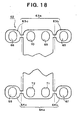
- lid forming portions 63a and 64a may be formed at the positions depicted in Fig. 17.
- lid forming portion 63a and lid forming portion 64a may be formed as separate portions 63b and 63c and separate portions 64b and 64c, respectively. Even in such structures, a target end plate 62 may be formed by turning back the respective lid forming portion, for example, at the respective dashed line shown in Figs. 17 and 18.
- Fig. 19 depicts a stacking-type, multi-flow, heat exchanger, according to a fourth embodiment of the present invention.
- lids 63 and 64 are formed as members separate from end plate 62.
- the brazing properties and the pressure resistance may be increased.
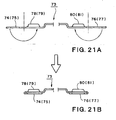
- Figs. 20 and 21 depict an end plate 73 of a stacking-type, multi-flow, heat exchanger and a process of manufacturing such a heat exchanger, according to a fifth embodiment of the present invention.
- the positional relationship between holes 74, 75, 76, and 77 and protruded portions 78, 79, 80, and 81 in end plate 73 is reversed as compared with that in end plate 62 of the third embodiment.
- Figs. 21A and 21B by turning back the respective hole forming portions, holes 74, 75, 76, and 77 are closed by the corresponding, respective protruded portions 78, 79, 80, and 81.
- the same function of the end plate may be achieved as that in the above-mentioned embodiments.
- the above-described end plates 9, 58, 62, and 73 may be formed by a single process such as pressing, stamping, or the like, and by turning back the predetermined portions of the end plates thus formed, target end plates may be readily manufactured. Further, by setting the outer surfaces of the respective, protruded portions of the end plate and the outer surface of the portion of the end plate connected to an outermost fin to be substantially flush, the brazing may be facilitated by using a simple brazing jig, as depicted in Fig. 12.
- the present invention may be applied to any stacking-type, multi-flow, heat exchanger comprising an end plate and, especially, may be applied suitably to a stacking-type, multi-flow, heat exchanger for use in an air conditioner for vehicles.
Abstract
Description
- The present invention relates to a stacking-type, multi-flow, heat exchanger comprising an end plate connected to an outermost layer of a heat exchanger core formed by stacking heat transfer tubes and fins alternately, and to methods for manufacturing such heat exchangers. Specifically, the present invention relates to an improved structure of a stacking-type, multi-flow, heat exchanger suitable as a heat exchanger for use in an air conditioner, in particular, for vehicles.
- A stacking-type, multi-flow, heat exchanger having alternately stacked heat transfer tubes and fins is known in the art, for example, as a heat exchanger having a structure shown in Figs. 22 and 23 (as shown in Japanese Utility Model Laid-Open No. 7-12778). In Figs. 22 and 23, a
heat exchanger 101 has aheat exchanger core 104 formed byheat transfer tubes 102 andfins 103 i.e., (outer fins) stacked alternately. Aside tank 105 is provided on one end ofheat exchanger core 104 in the stacking direction, for forming introduction/discharge passages of a heat exchange medium (e.g., refrigerant), and aflange 106 connected with an expansion valve (not shown) is connected toside tank 105. On the other end ofheat exchanger core 104, anend plate 107 is provided. - Each
heat transfer tube 102 is formed by connecting (e.g., brazing) a pair oftube plates 108, which have the same configuration, to each other. Projectingportions tube plate 108 for formingtanks heat exchanger core 104.Communication holes portions heat transfer tube 102, a pair oftube plates 108 are connected to each other, so that the respective projectingportions portions 109 and projectingportions 110 of a plurality ofheat transfer tubes 102 are connected to each other, respectively, to formtanks heat exchanger core 104.Communication holes outermost tube plate 108 at the end plate side are closed by projectingportions end plate 107, respectively. -
Heat exchanger 101 may be manufactured by temporarily assembling the respective members, and brazing the assembly at a later time in a furnace, wherein the assembly is held from both sides ofheat exchanger 101 in the stacking direction by a brazing jig (not shown). - In such a manufacturing method, however, because projecting
portions heat transfer tubes 102, and projecting portion 109 (110) ofoutermost tube plate 108 and projecting portion 115 (116) ofend plate 107, are assembled, such that they are in surface contact, a positional shift may occur when assembled or during brazing in a furnace. Consequently, the respective parts may not be connected properly. - To solve such a problem, Japanese Published Patent Application No. JP-A-5-87482 proposes the following structure, as depicted in Fig. 24. In this structure, each
heat transfer tube 117 is formed by afirst tube plate 118 and asecond tube plate 119. A raisedportion 122 is formed by creating a lip or edge on a projectingportion 121 for forming a tank ofsecond tube plate 119, and raisedportion 122 is inserted into acommunication hole 123 formed through a projectingportion 120 offirst tube plate 118 to prevent a positional shift at the time of the assembly. An opening 126 of raisedportion 122 ofoutermost tube plate 119 is closed by a projectingportion 125 of anend plate 124. - In such a structure, however, because it is difficult to ensure a sufficiently large area for brazing between projecting
portion 125 ofend plate 124 and raisedportion 122 of projectingportion 121 ofoutermost tube plate 119, insufficient brazing strength may be achieved. Further, because it is difficult to temporarily fixend plate 124 tooutermost tube plate 119 with a high degree of accuracy when assembled, the brazing accuracy may be reduced. - Accordingly, it would be desirable to provide improved structures of and methods for manufacturing stacking-type, multi-flow, heat exchangers, and especially, high-performance, stacking-type, multi-flow, heat exchangers, which may achieve a high degree of accuracy in the assembly of an end plate and various parts, and which may achieve a desirable connection of respective parts with both a high degree of accuracy in position and sufficient bonding strength, at a low cost.
- A stacking-type, multi-flow, heat exchanger, according to present invention, comprises a heat exchanger core comprising a plurality of heat transfer tubes each formed by connecting a pair of tube plates to each other and a plurality of fins, which are stacked alternately, and a tank portion formed at least at an end of the plurality of heat transfer tubes, and an end plate connected to an outermost tube plate of the heat exchanger core. The heat exchanger comprises a projecting portion provided on a surface of the outermost tube plate at least at an end portion of the outermost tube plate for forming a part of the tank, a raised portion with an opening formed on the projecting portion, and an engaging portion and a closing portion provided to the end plate for engaging the raised portion and for closing the opening of the raised portion.
- In such a stacking-type, multi-flow, heat exchanger, because the engaging portion, which engages the raised portion of the outermost tube plate, is provided integrally to the end plate, the end plate may be readily positioned relative to the outermost tube plate with a high degree of accuracy, and may be temporarily secured surely for a proper assembly. Therefore, because a positional shift of the end plate during the temporary assembly may be reduced or prevented, the brazing properties (e.g., the brazing accuracy) of the end plate and, ultimately, of the respective parts, may be enhanced. Such an engaging function may be readily achieved by a combination of the raised portion and a hole provided on the end plate engaging the raised portion.
- Further, because the closing portion, which closes the opening of the raised portion, is provided integrally to the end plate, the opening of the raised portion may be closed readily and certainly by setting the end plate. Further, because the periphery of the raised portion and the inner circumferential edge of the hole of the end plate and the end surface of the raised portion and the end plate may be more securely brazed, the brazing area between the end plate and the outermost tube plate may be enlarged, and the strength of the braze between both members may be increased. Such a closing function may be readily achieved by providing a lid to the end plate for closing the opening of the raised portion.
- Such a lid may be formed integrally with the end plate. For example, an opening inserted with the raised portion is provided to the end plate, an extended portion is formed on an end of the end plate, and by turning back the extended portion to close the opening of the raised portion, the above-described lid, having the closing function, may be readily formed.
- Further, the above-described end plate, having the hole for engaging the raised portion and the extended portion for forming the lid closing the opening of the raised portion, may be readily manufactured by a single process, such as pressing, stamping, or the like. Therefore, in the present invention, the number of parts and the number of processes, may not be increased substantially, and the cost for the manufacture may be reduced or prevented for rising.
- Moreover, if the lid is formed to have a portion protruded from a position of the raised portion, the strength of the lid may be increased. Further, if the degree of protrusion of the protruded portion is set, so that an outer surface of the protruded portion and an outer surface of a portion of the end plate connected to an outermost fin are formed to be substantially flush, the temporarily assembled heat exchanger may be securely fixed by using a simple jig for brazing. Therefore, the brazing property may be significantly improved.
- Thus, in the stacking-type, multi-flow, heat exchanger, according to the present invention, because the engaging portion and the closing portion are provided integrally to the end plate for engaging the raised portion of the outermost tube plate and for closing the opening of the raised portion (i.e., for closing an end of a tank), the end plate and, ultimately, the entire heat exchanger, may be assembled temporarily at a proper position with a high degree of accuracy, and the brazing properties may be significantly improved. Further, by providing the closing portion integrally to the end plate, increases in the number of the parts and the number of processes may be substantially prevented. This may contribute to lowering costs or reducing or eliminating cost increases.
- In addition, a method for manufacturing a stacking-type, multi-flow, heat exchanger, in which the heat exchanger may comprise a heat exchanger core comprising a plurality of heat transfer tubes, is provided. The method comprises the steps of: forming the heat exchanger tubes by connecting a pair of tube plates to each other; stacking the plurality of tubes alternatively with a plurality of fins to form said core; and forming a tank portion at least at an end of the core by connecting an end plate to an outermost tube plate of the core. The tank portion is formed by providing a projecting portion on a surface of said outermost tube plate at least at an end portion of the outermost tube plate for forming a part of the tank, surrounding an opening formed through the projecting portion with a raised portion, and providing an engaging portion and a closing portion to the end plate for engaging the raised portion and for closing the opening of the raised portion.
- Other objects, features, and advantages of the present invention will be apparent to persons of ordinary skill in the art from the following detailed description of preferred embodiments of the present invention and the accompanying drawings.
- For a more complete understanding of the present invention, the needs satisfied thereby, and the objects, features, and advantages thereof, reference now is made to the following description taken in connection with the accompanying drawings.
- Fig. 1 is a side view of a stacking-type, multi-flow, heat exchanger, according to a first embodiment of the present invention.
- Fig. 2 is a vertical, cross-sectional view of the heat exchanger depicted in Fig. 1, as viewed along Line II-II of Fig. 1.
- Fig. 3 is an exploded, perspective view of an outermost, heat transfer tube of the heat exchanger depicted in Fig. 1.
- Fig. 4 is a perspective view of an outermost, tube plate of the heat exchanger depicted in Fig. 1.
- Fig. 5 is an enlarged, partial, vertical, cross-sectional view of the heat exchanger depicted in Fig. 1.
- Fig. 6 is an enlarged, elevational view of an end plate of the heat exchanger depicted in Fig. 1.
- Fig. 7 is an enlarged, end view of the heat exchanger depicted in Fig. 1, as viewed along Line VII-VII of Fig. 1.
- Fig. 8 is an exploded, perspective view of an outermost, heat transfer tube of the heat exchanger depicted in Fig. 1, showing another embodiment different from that depicted in Fig. 3.
- Fig. 9 is an exploded, perspective view of an outermost, heat transfer tube of the heat exchanger depicted in Fig. 1, showing a further embodiment different from that depicted in Fig. 3.
- Fig. 10 is an exploded, vertical, cross-sectional view of the heat exchanger depicted in Fig. 1 and a jig, showing an assembly when the heat exchanger is brazed.
- Fig. 11 is a partial, vertical, cross-sectional view of a stacking-type, multi-flow, heat exchanger, according to a second embodiment of the present invention.
- Fig. 12 is a partial, vertical, cross-sectional view of a stacking-type, multi-flow, heat exchanger, according to a modification of the second embodiment depicted in Fig. 11, using another lid, and showing an assembly when the heat exchanger is brazed.
- Fig. 13 is a partial, vertical, cross-sectional view of a stacking-type, multi-flow, heat exchanger, according to a third embodiment of the present invention.
- Fig. 14 is an elevational view of an end plate of the heat exchanger depicted in Fig. 13.
- Figs. 15A and 15B are side views of an end plate of the heat exchanger depicted in Fig. 13, showing a turning-back process for manufacturing the end plate.
- Fig. 16 is an end view of the heat exchanger depicted in Fig. 13, as viewed along Line XVI-XVI of Fig. 13.
- Fig. 17 is an elevational view of an end plate of the heat exchanger depicted in Fig. 13, showing another embodiment different from that depicted in Fig. 14.
- Fig. 18 is an elevational view of an end plate of the heat exchanger depicted in Fig. 13, showing a further embodiment different from that depicted in Fig. 14.
- Fig. 19 is a partial, vertical, cross-sectional view of a stacking-type, multi-flow, heat exchanger, according to a fourth embodiment of the present invention.
- Fig. 20 is an elevational view of an end plate of a stacking-type, multi-flow, heat exchanger, according to a fifth embodiment of the present invention.
- Figs. 21A and 21B are side views of the end plate depicted in Fig. 20, showing a turning-back process for manufacturing the end plate.
- Fig. 22 is an exploded, side view of a known, stacking-type, multi-flow, heat exchanger.
- Fig. 23 is an enlarged, partial, vertical, cross-sectional view of the heat exchanger depicted in Fig. 22.
- Fig. 24 is an exploded, partial, side view of another known, stacking-type, multi-flow, heat exchanger.
-
- Referring to Figs. 1-7, a heat exchanger is depicted according to a first embodiment of the present invention.
Heat exchanger 1 is constructed as a stacking-type, multi-flow, heat exchanger. As depicted,heat exchanger 1 comprises aheat exchanger core 4 formed by a plurality ofheat transfer tubes 2 and a plurality ofouter fins 3 stacked alternately. Aside tank 5 is connected to one end ofheat exchanger core 4 in the stacking direction, and introduction/discharge passages of a heat exchange medium (e.g., refrigerant) into/from the heat exchanger are formed in theside tank 5. Aflange 8 having aninlet 6 and anoutlet 7 for heat exchange medium is connected toside tank 5. Anend plate 9 is connected to the other end ofheat exchanger core 4 in the stacking direction. - As depicted in Figs. 3 and 5, each
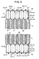
heat transfer tube 2 is formed by connecting a pair oftube plates 10 and 11 (i.e., afirst tube plate 10 and a second tube plate 11) to each other at their outer circumferential portions. Projectingportions tanks first tube plate 10.Passage forming portions 16 and 17 extending along the longitudinal direction offirst tube plate 10 are formed infirst tube plate 10. Similarly, projectingportions tanks second tube plate 11.Passage forming portions second tube plate 11 are formed insecond tube plate 11. In thissecond tube plate 11, as depicted in Figs. 4 and 5, raisedportions portions - As depicted in Figs. 3 and 5, inner passages for
heat exchange medium passage forming portions 16 and 22 and betweenpassage forming portions tube plates passages heat transfer tubes 2 thus formed,tanks projection portions projection portions tanks projection portions projection portions heat transfer tubes 2 are stacked, raisedportions portions second tube plates 11 are inserted into communication holes 34, 35, 36, and 37 formed through corresponding projectingportions first tube plates 10. Therefore, the whole ofheat exchanger core 4 including the respective tanks may be assembled temporarily without any positional shift. - Raised
portions second tube plate 11 of an outermostheat transfer tube 2 are inserted intoholes end plate 9. In this embodiment, an engagingportion 48 is formed by inserting the respective raised portions into each of the corresponding holes ofend plate 9. -
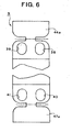
Openings portions second tube plate 11 of the outermost,heat transfer tube 2 are closed by alid 44 formed integrally withend plate 9.Openings portions second tube plate 11 of the outermostheat transfer tube 2 are closed by alid 47 formed integrally withend plate 9. As depicted in Fig. 6, theselids extended portions 44a and 47a, formed integrally withend plate 9, at a position of the respective dashed lines of Fig. 6. By this turning-back process,openings portions lids lids form closing portions 49 for closingopenings portions heat transfer tube 2. - Thus, in this embodiment, engaging
portions 48 andclosing portions 49 are formed integrally withend plate 9.End plate 9 having the above-describedholes portions 48 andlids 44 and 47 (i.e.,extended portions 44a and 47a) formingclosing portions 49 may be formed by a single process, such as pressing, stamping, or the like. Therefore, increases in the number of the parts and the number of the manufacturing method steps may be substantially prevented, and the cost for the manufacture may be effectively reduced or prevented from rising. - In
heat exchanger 1 described above, the respective parts are assembled temporarily, and the assembly is brazed at a later time in a furnace. Therefore, if the positional relationship between the respective parts is not properly set, the brazing properties may be markedly reduced. In particular, in a known, stacking-type, multi-flow, heat exchanger, although an end plate is precisely positioned during assembly, it is difficult to maintain this positioning during brazing. Further, because the brazing area between an end plate and an outermost, tube plate .(eg, an outermost second tube plate) is limited, it is difficult to ensure a sufficient connection strength of this portion. - In this embodiment, however, engaging
portion 48 and closingportion 49 are provided integrally toend plate 9. In particular, because respective raisedportions second tube plate 11 of an outermost,heat transfer tube 2 are inserted into correspondingholes end plate 9, theend plate 9 may be accurately positioned relative to the outermost,second tube plate 11 of the outermost,heat transfer tube 2. Therefore, when temporarily assembled, a positional shift ofend plate 9 may be reduced or prevented,end plate 9 and, ultimately, theentire heat exchanger 1 including other parts, may be maintained in position even during brazing, and the brazing properties may be significantly improved. - Moreover,
lids openings portions end plate 9. Therefore, by formingextended portions 44a and 47a by pressing, stamping, or the like and turning back theextended portions 44a and 47a to engage outermost,second tube plate 11 andform lids openings portions portions holes end plate 9 and the portions between the end surfaces of respective raisedportions lids end plate 9 are brazed, the size of brazing area may be maintained or increased. Therefore, the brazing properties therebetween may be increased, and the pressure resistance at the brazed portions may be increased. - Although the raised portions are provided to all of the projecting portions of outermost,
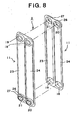
second tube plate 11 in the above-described embodiment, if a raised portion is provided to at least one projecting portion, the object of the present invention may be achieved. In particular, by engaging a raised portion, the outer shape of which is formed as an oval or the like, with a hole formed throughend plate 9 with a corresponding shape,end plate 9 may be temporarily fixed relative to outermost,tube plate 11 with a high degree of accuracy, and therefore, the brazing properties may be improved. Further, as depicted in Figs. 8 and 9, raised portions may be provided to any two projecting portions. By thus forming outermost,second tube plate 11, each ofheat transfer tubes 2 may be formed from a pair of thesame tube plates 11. For example, in the embodiment depicted in Figs. 8 and 9,heat transfer tube 2 may be formed by connecting atube plate 11 to anothertube plate 11 having substantially the same structure, but reversed, in the vertical direction. Thus, when a plurality of projecting portions are provided, the object of the present invention may be achieved by forming a raised portion on at least one projecting portion. - Further,
outer surfaces lids outer surface 52 of a portion ofend plate 9 connected to outermost,outer fin 3 in the above-described embodiment, as depicted in Fig. 10. Nevertheless, by formingportions brazing jig 53 to be brought into contact withouter surfaces lids jig 53 may be exhibited more properly, and during brazing in a furnace, a positional shift of the parts ofheat exchanger 1 assembled temporarily may be reduced or prevented. - Fig. 11 depicts a stacking-type, multi-flow, heat exchanger, according to a second embodiment of the present invention. The explanation of the same members as those described with respect to first embodiment is omitted by providing the same reference numerals as those in the first embodiment. In this embodiment,
lids closing openings portions end plate 58. Moreover, in this embodiment,end plate 58 may be positioned with certainty and assembled with a high degree of accuracy, and the brazing properties and the pressure resistance may be increased. - As depicted in Fig. 12, by forming
lids outer surfaces lids outer surface 61 of a portion ofend plate 58, which is connected to the outermost fin. Therefore, it is not necessary to providethicker portions jig 53 as in the first embodiment, and the structure of thebrazing jig 53 may be simplified and the fixing strength thereof may be increased. Moreover, by forminglids - Figs. 13 to 16 depict a stacking-type, multi-flow, heat exchanger and the method for manufacturing such a heat exchanger, according to a third embodiment of the present invention. In this embodiment, as depicted in Fig. 14,
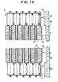
lid forming portions end plate 62 at both end portions ofend plate 62 in its longitudinal direction.Protruded portions lid forming portions lid forming portions lids lids end plate 62, respectively, as depicted in Fig. 16. - Moreover, in this embodiment, because raised
portions second tube plate 11 are inserted intoholes end plate 62, respectively,end plate 62 may be positioned with a high degree of accuracy similar to that in the first embodiment, and the brazing properties may be improved. Further, in this embodiment, because protrudedportions lids end plate 62,openings lid forming portions lid forming portion 63a andlid forming portion 64a may be formed asseparate portions separate portions 64b and 64c, respectively. Even in such structures, atarget end plate 62 may be formed by turning back the respective lid forming portion, for example, at the respective dashed line shown in Figs. 17 and 18. - Fig. 19 depicts a stacking-type, multi-flow, heat exchanger, according to a fourth embodiment of the present invention. In this embodiment,
lids end plate 62. Moreover, in this embodiment, similar to that depicted in the third embodiment, the brazing properties and the pressure resistance may be increased. - Figs. 20 and 21 depict an
end plate 73 of a stacking-type, multi-flow, heat exchanger and a process of manufacturing such a heat exchanger, according to a fifth embodiment of the present invention. In this embodiment, the positional relationship betweenholes portions end plate 73 is reversed as compared with that inend plate 62 of the third embodiment. As depicted in Figs. 21A and 21B, by turning back the respective hole forming portions, holes 74, 75, 76, and 77 are closed by the corresponding, respective protrudedportions - The above-described
end plates - The present invention may be applied to any stacking-type, multi-flow, heat exchanger comprising an end plate and, especially, may be applied suitably to a stacking-type, multi-flow, heat exchanger for use in an air conditioner for vehicles.
Claims (15)
- A stacking-type, multi-flow, heat exchanger comprising a heat exchanger core comprising a plurality of heat transfer tubes each formed by connecting a pair of tube plates to each other and a plurality of fins, which are stacked alternately, and a tank portion formed at least at an end of said plurality of heat transfer tubes, and an end plate connected to an outermost tube plate of said heat exchanger core, characterized in that said heat exchanger comprises:a projecting portion provided on a surface of said outermost tube plate at least at an end portion of said outermost tube plate for forming a part of said tank;a raised portion with an opening formed through said projecting portion; andan engaging portion and a closing portion provided to said end plate for engaging said raised portion and for closing said opening of said raised portion.
- The heat exchanger of claim 1, wherein said engaging portion comprises a hole provided through said end plate for engaging said raised portion.
- The heat exchanger of claim 1 or 2, wherein said closing portion comprises a lid closing said opening of said raised portion.
- The heat exchanger of claim 3, wherein said lid is formed integrally with said end plate.
- The heat exchanger of claim 4, wherein said lid is formed by turning back an extended portion formed on an end of said end plate.
- The heat exchanger of any of claims 3 to 5, wherein said lid is formed to comprise a portion protruded from a position of said raised portion.
- The heat exchanger of claim 6, wherein an outer surface of said protruded portion and an outer surface of a portion of said end plate connected to an outermost fin are formed to be substantially flush.
- A method for manufacturing a stacking-type, multi-flow, heat exchanger, said heat exchanger comprising a heat exchanger core comprising a plurality of heat transfer tubes, said method comprising the steps of:forming said heat exchanger tubes by connecting a pair of tube plates to each other;stacking said plurality of tubes alternatively with a plurality of fins to form said core; andforming a tank portion at least at an end of said core by connecting an end plate to an outermost tube plate of said core, wherein said tank portion is formed by providing a projecting portion on a surface of said outermost tube plate at least at an end portion of said outermost tube plate for forming a part of said tank, surrounding an opening formed through said projecting portion with a raised portion, and providing an engaging portion and a closing portion to said end plate for engaging said raised portion and for closing said opening of said raised portion.
- The method of claim 8, wherein said engaging portion comprises a hole provided through said end plate for engaging said raised portion.
- The method of claim 8 or 9, wherein said closing portion comprises a lid closing said opening of said raised portion.
- The method of claim 10, further comprising the step of forming said lid integrally with said end plate.
- The method of claim 11, wherein the step of forming said lid further comprises turning back an extended portion formed on an end of said end plate.
- The method of any of claims 10 to 12, further comprising the step of forming said lid to comprise a portion protruded from a position of said raised portion.
- The method of claim 13, wherein the step of forming said lid further comprises forming an outer surface of said protruded portion and an outer surface of a portion of said end plate connected to an outermost fin to be substantially flush.
- The method of any of claims 8 to 14, further comprising the step of fixing said assembled heat exchanger with a jig and brazing said heat exchanger.
Applications Claiming Priority (2)
| Application Number | Priority Date | Filing Date | Title |
|---|---|---|---|
| JP2004030804 | 2004-02-06 | ||
| JP2004030804A JP4426328B2 (en) | 2004-02-06 | 2004-02-06 | Laminate heat exchanger |
Publications (2)
| Publication Number | Publication Date |
|---|---|
| EP1562014A1 true EP1562014A1 (en) | 2005-08-10 |
| EP1562014B1 EP1562014B1 (en) | 2006-12-20 |
Family
ID=34675559
Family Applications (1)
| Application Number | Title | Priority Date | Filing Date |
|---|---|---|---|
| EP05250255A Expired - Fee Related EP1562014B1 (en) | 2004-02-06 | 2005-01-19 | Stacking-type, multi-flow, heat exchanger |
Country Status (6)
| Country | Link |
|---|---|
| US (1) | US7520319B2 (en) |
| EP (1) | EP1562014B1 (en) |
| JP (1) | JP4426328B2 (en) |
| CN (1) | CN100554861C (en) |
| DE (1) | DE602005000336T2 (en) |
| TW (1) | TWI336760B (en) |
Cited By (5)
| Publication number | Priority date | Publication date | Assignee | Title |
|---|---|---|---|---|
| EP1686339A1 (en) * | 2005-01-24 | 2006-08-02 | Halla Climate Control Corporation | Heat exchanger |
| WO2013020828A1 (en) | 2011-08-11 | 2013-02-14 | Mahle International Gmbh | Plate heat exchanger |
| DE102011080824A1 (en) | 2011-08-11 | 2013-02-14 | Mahle International Gmbh | Plate heat exchanger |
| US8662152B2 (en) | 2007-02-26 | 2014-03-04 | Alfa Laval Corporate Ab | Plate heat exchanger |
| EP2660531A4 (en) * | 2010-12-28 | 2017-08-23 | Mitsubishi Heavy Industries Automotive Thermal Systems Co., Ltd. | Method for manufacturing hot-water heater, and hot-water heater manufactured thereby |
Families Citing this family (9)
| Publication number | Priority date | Publication date | Assignee | Title |
|---|---|---|---|---|
| JP2005337573A (en) | 2004-05-26 | 2005-12-08 | Sanden Corp | Heat exchanger |
| JP4493407B2 (en) | 2004-05-27 | 2010-06-30 | サンデン株式会社 | Laminated heat exchanger and manufacturing method thereof |
| US7568520B2 (en) * | 2005-06-21 | 2009-08-04 | Calsonic Kansei Corporation | Oil cooler |
| DE102005058769B4 (en) * | 2005-12-09 | 2016-11-03 | Modine Manufacturing Co. | Intercooler |
| SE534775C2 (en) | 2010-04-08 | 2011-12-13 | Titanx Engine Cooling Holding Ab | Heat exchanger with leakage flow barrier, oil cooling system and method for cooling oil |
| SE536042C2 (en) * | 2010-06-16 | 2013-04-09 | Titanx Engine Cooling Holding Ab | Heat exchanger with extended heat transfer surface around attachment points |
| FR2973106B1 (en) * | 2011-03-23 | 2013-03-29 | Valeo Systemes Thermiques | REINFORCEMENT OF CONNECTION BETWEEN PLATES OF A HEAT EXCHANGER |
| DE102014002801B4 (en) * | 2014-02-26 | 2017-10-05 | Modine Manufacturing Co. | Brazed heat exchanger |
| CN105910475B (en) * | 2016-05-30 | 2018-03-27 | 江阴市亚龙换热设备有限公司 | Plate type heat exchanger bottom plate |
Citations (6)
| Publication number | Priority date | Publication date | Assignee | Title |
|---|---|---|---|---|
| US4274482A (en) * | 1978-08-21 | 1981-06-23 | Nihon Radiator Co., Ltd. | Laminated evaporator |
| JPS62288497A (en) * | 1986-06-04 | 1987-12-15 | Nippon Denso Co Ltd | Lamination type heat exchanger |
| EP0590306A1 (en) * | 1992-08-31 | 1994-04-06 | Mitsubishi Jukogyo Kabushiki Kaisha | Stacked heat exchanger |
| JPH0989490A (en) * | 1995-09-21 | 1997-04-04 | Showa Alum Corp | Laminated type heat exchanger |
| JP2001116485A (en) * | 1999-10-22 | 2001-04-27 | Showa Alum Corp | Laminated heat exchanger |
| US6408940B1 (en) * | 1998-12-30 | 2002-06-25 | Valeo Climatisation | Heating, ventilation and/or air-conditioning device including a thermal loop equipped with an evaporator |
Family Cites Families (34)
| Publication number | Priority date | Publication date | Assignee | Title |
|---|---|---|---|---|
| GB2167699B (en) * | 1984-12-04 | 1988-04-27 | Sanden Corp | A method for producing a heat exchanger |
| FR2625172B1 (en) * | 1987-12-24 | 1990-04-20 | Apple Computer France | PACKAGING WITH AIR BAGS |
| US5088193A (en) * | 1988-09-02 | 1992-02-18 | Sanden Corporation | Method for manufacturing a heat exchanger |
| US5336524A (en) * | 1988-11-08 | 1994-08-09 | Diesel Kiki Co., Ltd. | Evaporator |
| US5099576A (en) * | 1989-08-29 | 1992-03-31 | Sanden Corporation | Heat exchanger and method for manufacturing the heat exchanger |
| US5172762A (en) * | 1989-10-20 | 1992-12-22 | Sanden Corporation | Heat exchanger |
| US5119552A (en) * | 1990-02-16 | 1992-06-09 | Sanden Corporation | Method for manufacturing header pipe of heat exchanger |
| JP2513332Y2 (en) * | 1990-02-22 | 1996-10-02 | サンデン株式会社 | Heat exchanger |
| US5214847A (en) * | 1990-03-07 | 1993-06-01 | Sanden Corporation | Method for manufacturing a heat exchanger |
| US5174373A (en) * | 1990-07-13 | 1992-12-29 | Sanden Corporation | Heat exchanger |
| JPH04177094A (en) * | 1990-11-13 | 1992-06-24 | Sanden Corp | Laminated type heat exchanger |
| JP2537507Y2 (en) | 1991-03-08 | 1997-06-04 | サンデン株式会社 | Heat exchanger |
| US5255672A (en) * | 1991-08-07 | 1993-10-26 | Jinotti Walter J | Dual-purpose catheter assembly |
| US5125453A (en) * | 1991-12-23 | 1992-06-30 | Ford Motor Company | Heat exchanger structure |
| JPH06129791A (en) * | 1992-10-15 | 1994-05-13 | Sanden Corp | Heat exchanger and method for fixing bracket thereof |
| JPH0755384A (en) * | 1993-08-19 | 1995-03-03 | Sanden Corp | Multi-tube heat exchanger |
| US5632331A (en) * | 1993-09-30 | 1997-05-27 | Sanden Corporation | Heat exchanger |
| US5413169A (en) * | 1993-12-17 | 1995-05-09 | Ford Motor Company | Automotive evaporator manifold |
| CN1109232C (en) * | 1993-12-28 | 2003-05-21 | 昭和电工株式会社 | Plate heat exchanger |
| JPH08327281A (en) * | 1995-05-30 | 1996-12-13 | Sanden Corp | Header for heat exchanger |
| JPH08327276A (en) * | 1995-05-30 | 1996-12-13 | Sanden Corp | Multi-tube type heat exchanger |
| JP3393957B2 (en) * | 1995-05-30 | 2003-04-07 | サンデン株式会社 | Heat exchanger fluid supply / drain pipe joining method |
| DE19543149C2 (en) * | 1995-11-18 | 2000-09-14 | Behr Gmbh & Co | Heat exchangers, especially refrigerant evaporators |
| JP3530660B2 (en) * | 1995-12-14 | 2004-05-24 | サンデン株式会社 | Heat exchanger tank structure |
| JPH09280781A (en) * | 1996-04-17 | 1997-10-31 | Sanden Corp | Multitubular heat exchanger |
| JPH1078269A (en) * | 1996-09-04 | 1998-03-24 | Showa Alum Corp | Multilayer evaporator |
| JPH10185463A (en) * | 1996-12-19 | 1998-07-14 | Sanden Corp | Heat-exchanger |
| JP3593434B2 (en) * | 1997-02-06 | 2004-11-24 | サンデン株式会社 | Heat exchanger unit |
| JP3912836B2 (en) * | 1997-02-21 | 2007-05-09 | サンデン株式会社 | Heat exchanger |
| JP4153106B2 (en) * | 1998-10-23 | 2008-09-17 | サンデン株式会社 | Heat exchanger |
| FR2788118B1 (en) * | 1998-12-30 | 2003-04-18 | Valeo Climatisation | HEATING, VENTILATION AND / OR AIR CONDITIONING DEVICE COMPRISING A THERMAL BURNER EQUIPPED WITH AN EVAPORATOR |
| FR2788117B1 (en) * | 1998-12-30 | 2001-03-02 | Valeo Climatisation | HEATING, VENTILATION AND / OR AIR CONDITIONING DEVICE COMPRISING A THERMAL LOOP EQUIPPED WITH AN EVAPORATOR |
| JP3911574B2 (en) * | 2000-01-08 | 2007-05-09 | 漢拏空調株式会社 | Plate for laminated heat exchanger with improved heat exchange performance and heat exchanger using the same |
| FR2826438B1 (en) * | 2001-06-20 | 2004-01-23 | Valeo Climatisation | ARRANGEMENT OF INPUT AND OUTPUT TUBES FOR AN EVAPORATOR |
-
2004
- 2004-02-06 JP JP2004030804A patent/JP4426328B2/en not_active Expired - Fee Related
-
2005
- 2005-01-19 DE DE602005000336T patent/DE602005000336T2/en active Active
- 2005-01-19 EP EP05250255A patent/EP1562014B1/en not_active Expired - Fee Related
- 2005-01-27 US US11/050,811 patent/US7520319B2/en not_active Expired - Fee Related
- 2005-02-03 TW TW094103313A patent/TWI336760B/en not_active IP Right Cessation
- 2005-02-06 CN CNB2005100078702A patent/CN100554861C/en active Active
Patent Citations (6)
| Publication number | Priority date | Publication date | Assignee | Title |
|---|---|---|---|---|
| US4274482A (en) * | 1978-08-21 | 1981-06-23 | Nihon Radiator Co., Ltd. | Laminated evaporator |
| JPS62288497A (en) * | 1986-06-04 | 1987-12-15 | Nippon Denso Co Ltd | Lamination type heat exchanger |
| EP0590306A1 (en) * | 1992-08-31 | 1994-04-06 | Mitsubishi Jukogyo Kabushiki Kaisha | Stacked heat exchanger |
| JPH0989490A (en) * | 1995-09-21 | 1997-04-04 | Showa Alum Corp | Laminated type heat exchanger |
| US6408940B1 (en) * | 1998-12-30 | 2002-06-25 | Valeo Climatisation | Heating, ventilation and/or air-conditioning device including a thermal loop equipped with an evaporator |
| JP2001116485A (en) * | 1999-10-22 | 2001-04-27 | Showa Alum Corp | Laminated heat exchanger |
Non-Patent Citations (3)
| Title |
|---|
| PATENT ABSTRACTS OF JAPAN vol. 012, no. 179 (M - 701) 26 May 1988 (1988-05-26) * |
| PATENT ABSTRACTS OF JAPAN vol. 1997, no. 08 29 August 1997 (1997-08-29) * |
| PATENT ABSTRACTS OF JAPAN vol. 2000, no. 21 3 August 2001 (2001-08-03) * |
Cited By (10)
| Publication number | Priority date | Publication date | Assignee | Title |
|---|---|---|---|---|
| EP1686339A1 (en) * | 2005-01-24 | 2006-08-02 | Halla Climate Control Corporation | Heat exchanger |
| US7523781B2 (en) | 2005-01-24 | 2009-04-28 | Halls Climate Control Corporation | Heat exchanger |
| US8662152B2 (en) | 2007-02-26 | 2014-03-04 | Alfa Laval Corporate Ab | Plate heat exchanger |
| EP2660531A4 (en) * | 2010-12-28 | 2017-08-23 | Mitsubishi Heavy Industries Automotive Thermal Systems Co., Ltd. | Method for manufacturing hot-water heater, and hot-water heater manufactured thereby |
| WO2013020828A1 (en) | 2011-08-11 | 2013-02-14 | Mahle International Gmbh | Plate heat exchanger |
| DE102011080828A1 (en) | 2011-08-11 | 2013-02-14 | Mahle International Gmbh | Plate heat exchanger |
| DE102011080824A1 (en) | 2011-08-11 | 2013-02-14 | Mahle International Gmbh | Plate heat exchanger |
| WO2013020823A1 (en) | 2011-08-11 | 2013-02-14 | Mahle International Gmbh | Plate heat exchanger |
| US9863715B2 (en) | 2011-08-11 | 2018-01-09 | Mahle International Gmbh | Plate heat exchanger with flanged base or connecting plate |
| US10048013B2 (en) | 2011-08-11 | 2018-08-14 | Mahle International Gmbh | Plate heat exchanger and base thereof |
Also Published As
| Publication number | Publication date |
|---|---|
| CN1651848A (en) | 2005-08-10 |
| DE602005000336T2 (en) | 2007-04-19 |
| CN100554861C (en) | 2009-10-28 |
| US7520319B2 (en) | 2009-04-21 |
| DE602005000336D1 (en) | 2007-02-01 |
| US20050173101A1 (en) | 2005-08-11 |
| JP2005221175A (en) | 2005-08-18 |
| TWI336760B (en) | 2011-02-01 |
| JP4426328B2 (en) | 2010-03-03 |
| EP1562014B1 (en) | 2006-12-20 |
| TW200533874A (en) | 2005-10-16 |
Similar Documents
| Publication | Publication Date | Title |
|---|---|---|
| EP1562014B1 (en) | Stacking-type, multi-flow, heat exchanger | |
| US20170198975A1 (en) | Heat Exchanger Construction | |
| WO2005103597A1 (en) | Two-piece mounting bracket for heat exchanger | |
| US7311138B2 (en) | Stacking-type, multi-flow, heat exchangers and methods for manufacturing such heat exchangers | |
| JPH07190559A (en) | Laminated heat exchanger | |
| JPH10232097A (en) | Heat-exchanger | |
| JP2000304486A (en) | Heat exchanger and manufacture thereof | |
| JP2573421Y2 (en) | Heat exchanger | |
| JPH0722620Y2 (en) | Aluminum condenser for air conditioner | |
| JP2000018872A (en) | Plate type heat exchanger | |
| JP2005291671A (en) | Stacked heat exchanger | |
| JPH04278196A (en) | Heat exchanger | |
| EP2057434B1 (en) | Alternating plate headerless heat exchangers | |
| JPH0717962Y2 (en) | Heat exchanger | |
| JP4041727B2 (en) | Tube for heat exchanger | |
| JP4017707B2 (en) | Stacked heat exchanger | |
| JP2603148Y2 (en) | Heat exchanger | |
| JP2523238B2 (en) | Heat exchanger | |
| JP2002147983A (en) | Laminated heat exchanger | |
| JPH11294989A (en) | Heat exchanger | |
| JP2597831Y2 (en) | Heat exchanger | |
| JP2002115988A (en) | Stacked heat exchanger | |
| JPH01217195A (en) | Heat exchanger | |
| JPH03295Y2 (en) | ||
| JPH0926282A (en) | Heat exchanger |
Legal Events
| Date | Code | Title | Description |
|---|---|---|---|
| PUAI | Public reference made under article 153(3) epc to a published international application that has entered the european phase |
Free format text: ORIGINAL CODE: 0009012 |
|
| AK | Designated contracting states |
Kind code of ref document: A1 Designated state(s): AT BE BG CH CY CZ DE DK EE ES FI FR GB GR HU IE IS IT LI LT LU MC NL PL PT RO SE SI SK TR |
|
| AX | Request for extension of the european patent |
Extension state: AL BA HR LV MK YU |
|
| GRAP | Despatch of communication of intention to grant a patent |
Free format text: ORIGINAL CODE: EPIDOSNIGR1 |
|
| 17P | Request for examination filed |
Effective date: 20060113 |
|
| AKX | Designation fees paid |
Designated state(s): DE FR |
|
| GRAS | Grant fee paid |
Free format text: ORIGINAL CODE: EPIDOSNIGR3 |
|
| GRAA | (expected) grant |
Free format text: ORIGINAL CODE: 0009210 |
|
| AK | Designated contracting states |
Kind code of ref document: B1 Designated state(s): DE FR |
|
| REF | Corresponds to: |
Ref document number: 602005000336 Country of ref document: DE Date of ref document: 20070201 Kind code of ref document: P |
|
| ET | Fr: translation filed | ||
| PLBE | No opposition filed within time limit |
Free format text: ORIGINAL CODE: 0009261 |
|
| STAA | Information on the status of an ep patent application or granted ep patent |
Free format text: STATUS: NO OPPOSITION FILED WITHIN TIME LIMIT |
|
| 26N | No opposition filed |
Effective date: 20070921 |
|
| PGFP | Annual fee paid to national office [announced via postgrant information from national office to epo] |
Ref country code: DE Payment date: 20130131 Year of fee payment: 9 Ref country code: FR Payment date: 20130128 Year of fee payment: 9 |
|
| REG | Reference to a national code |
Ref country code: DE Ref legal event code: R119 Ref document number: 602005000336 Country of ref document: DE |
|
| REG | Reference to a national code |
Ref country code: DE Ref legal event code: R119 Ref document number: 602005000336 Country of ref document: DE Effective date: 20140801 |
|
| PG25 | Lapsed in a contracting state [announced via postgrant information from national office to epo] |
Ref country code: DE Free format text: LAPSE BECAUSE OF NON-PAYMENT OF DUE FEES Effective date: 20140801 |
|
| REG | Reference to a national code |
Ref country code: FR Ref legal event code: ST Effective date: 20140930 |
|
| PG25 | Lapsed in a contracting state [announced via postgrant information from national office to epo] |
Ref country code: FR Free format text: LAPSE BECAUSE OF NON-PAYMENT OF DUE FEES Effective date: 20140131 |