EP1561998A1 - Diffuseur pour turboréacteur - Google Patents
Diffuseur pour turboréacteur Download PDFInfo
- Publication number
- EP1561998A1 EP1561998A1 EP05290094A EP05290094A EP1561998A1 EP 1561998 A1 EP1561998 A1 EP 1561998A1 EP 05290094 A EP05290094 A EP 05290094A EP 05290094 A EP05290094 A EP 05290094A EP 1561998 A1 EP1561998 A1 EP 1561998A1
- Authority
- EP
- European Patent Office
- Prior art keywords
- diffuser
- frustoconical
- wall
- combustion chamber
- compressor
- Prior art date
- Legal status (The legal status is an assumption and is not a legal conclusion. Google has not performed a legal analysis and makes no representation as to the accuracy of the status listed.)
- Granted
Links
- 238000002485 combustion reaction Methods 0.000 claims abstract description 42
- 238000011144 upstream manufacturing Methods 0.000 claims abstract description 15
- 239000000725 suspension Substances 0.000 claims abstract description 13
- 238000000034 method Methods 0.000 description 4
- 238000005070 sampling Methods 0.000 description 4
- 238000004519 manufacturing process Methods 0.000 description 1
Images

Classifications
-
- F—MECHANICAL ENGINEERING; LIGHTING; HEATING; WEAPONS; BLASTING
- F04—POSITIVE - DISPLACEMENT MACHINES FOR LIQUIDS; PUMPS FOR LIQUIDS OR ELASTIC FLUIDS
- F04D—NON-POSITIVE-DISPLACEMENT PUMPS
- F04D29/00—Details, component parts, or accessories
- F04D29/40—Casings; Connections of working fluid
- F04D29/52—Casings; Connections of working fluid for axial pumps
- F04D29/54—Fluid-guiding means, e.g. diffusers
- F04D29/541—Specially adapted for elastic fluid pumps
- F04D29/542—Bladed diffusers
-
- F—MECHANICAL ENGINEERING; LIGHTING; HEATING; WEAPONS; BLASTING
- F23—COMBUSTION APPARATUS; COMBUSTION PROCESSES
- F23R—GENERATING COMBUSTION PRODUCTS OF HIGH PRESSURE OR HIGH VELOCITY, e.g. GAS-TURBINE COMBUSTION CHAMBERS
- F23R3/00—Continuous combustion chambers using liquid or gaseous fuel
- F23R3/42—Continuous combustion chambers using liquid or gaseous fuel characterised by the arrangement or form of the flame tubes or combustion chambers
- F23R3/60—Support structures; Attaching or mounting means
-
- F—MECHANICAL ENGINEERING; LIGHTING; HEATING; WEAPONS; BLASTING
- F05—INDEXING SCHEMES RELATING TO ENGINES OR PUMPS IN VARIOUS SUBCLASSES OF CLASSES F01-F04
- F05B—INDEXING SCHEME RELATING TO WIND, SPRING, WEIGHT, INERTIA OR LIKE MOTORS, TO MACHINES OR ENGINES FOR LIQUIDS COVERED BY SUBCLASSES F03B, F03D AND F03G
- F05B2230/00—Manufacture
- F05B2230/60—Assembly methods
- F05B2230/604—Assembly methods using positioning or alignment devices for aligning or centering, e.g. pins
- F05B2230/606—Assembly methods using positioning or alignment devices for aligning or centering, e.g. pins using maintaining alignment while permitting differential dilatation
Definitions
- the present invention relates to a turbojet diffuser, this diffuser being arranged between a compressor and a chamber of combustion in the turbojet.
- the diffuser is often fixed inside an outer casing of the combustion chamber by a thin wall or a frustoconical web extending from a longitudinal wall external diffuser in the direction of the combustion chamber and which is welded at its radially outer end to the outer casing of the combustion chamber.
- the purpose of the invention is in particular to provide a simple solution, inexpensive and economical solution to the problem of the dismountable diffuser in a turbojet.
- a diffuser for turbojet engine this diffuser being arranged between a compressor and a combustion chamber and fixed to an outer casing of the combustion chamber by means of suspension that extend between this outer casing and a wall outer longitudinal axis of the diffuser, characterized in that the means for suspension comprise a first frustoconical wall extending from the outer longitudinal wall of the diffuser in the direction of the chamber of combustion, and a second frustoconical wall connected to the first wall frustoconical and extending between the first frustoconical wall and the casing outside the combustion chamber in the direction of the compressor.
- the two frustoconical fastening walls of the diffuser according to the invention make it possible to circumvent the downstream advancement of space ring that surrounds the compressor and therefore to fix the diffuser to the housing outside the combustion chamber without changing the specifications of compressor air sampling and without the use of structural arms.
- the attachment of the second frustoconical wall on the outer casing of the combustion chamber is at the level of connection between the outer casings of the compressor and the chamber of combustion, particularly simple by inserting a flange annular of the aforementioned second frustoconical wall between the flanges annular connection of compressor housings and chamber annular.
- first frustoconical wall of suspension means is connected to the upstream end of the wall outer longitudinal section of the diffuser, which ensures optimal alignment of the upstream end of the diffuser on the downstream end of the compressor, so a fixed blade of the upstream end of the diffuser is well positioned and centered on the axis of the compressor.
- the biconical shape of the suspension means increases the flexibility of the diffuser attachment and reduces the constraints on the connection on the external longitudinal wall of the diffuser, which increases its life.
- the two walls or frustoconical webs of the suspension means are formed of a single piece and their junction comprises a rib ring extending towards the combustion chamber.
- This annular rib stiffens the junction area of the two walls or sails frustoconical and distributes the stresses in this area.
- She has preferably a thickness between 1.3 and 1.7 times the thickness of the sails, and optimally a thickness equal to about 1.5 times the thickness of the sails.
- This rib has, in its simplest embodiment, a shape cylindrical centered on the axis of the turbojet engine.
- it can extend in the extension of the bisector of the angle formed between the two walls or frustoconical sails suspension means of the diffuser.
- an advantage of the diffuser according to the invention is it can be dismounted in a simple way while respecting the specifications compressor air sampling.
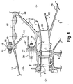
- reference numeral 1 denotes a diffuser according to the technique known, arranged between a compressor 2 upstream and a chamber of combustion 3 downstream in a turbojet engine.
- the compressor 2 is a high pressure compressor and includes several stages of moving blades 4, 5 mounted on a rotor 6 of the turbojet engine by suitable means for example of the type with a tail dovetail 7, and fixed blade stages 8 forming rectifiers, mounted on a stator 9 of the turbojet engine by appropriate means.
- Figure 1 represented only two stages of moving blades 4 and 5 and a blade stage fixed 8 between the two stages of blades 4 and 5.
- An annular space 10 is delimited around the stator 9 of the compressor 2 by an outer casing 11 and a transverse wall rear 12 which is mounted by an inner annular flange 13 on a flange annular 14 of the stator 9 and an external annular flange 15 on a flange ring 16 of the outer casing 11 of the compressor 2.
- the combustion chamber 3 is delimited by an outer casing 17 and by an inner casing (not shown), the outer casing 17 being fixed on the upstream side on the outer casing 11 of the compressor 2 by means of a annular flange 18 applied to the outer annular flange 15 of the wall transverse 12 of the compressor 2, the fixing of the three flanges being ensured by appropriate means of the screw-nut type 19.
- the rear transverse wall 12 extends downstream around an upstream part of the diffuser 1.
- the diffuser 1 comprises fixed vanes 20 arranged radially between an outer longitudinal wall 21 and an inner longitudinal wall 22 for guiding the air leaving the compressor 2 to the chamber of combustion 3.
- the diffuser 1 is fixed to the lower part of the outer casing 17 of the combustion chamber 3 by a thin wall or sail 23 of frustoconical shape which extends from the outer longitudinal wall 21 of the diffuser 1 in the direction of the firebox 3 and that is welded at its radially outer end 24 to the outer casing 17 of the combustion chamber 3.
- the wall or sail 23 of frustoconical shape is attached to the outer longitudinal wall 21 of the diffuser in the part median of this wall 21.
- the diffuser 1 is also fixed by a wall or internal sail 25 of frustoconical shape which extends from the wall internal longitudinal 22 of the diffuser 1 in the direction of the chamber of combustion 3, to an internal casing (not shown) of the chamber of
- a cylindrical wall 26 extends from the wall external longitudinal 21 of the diffuser 1 in the direction of the compressor 2 and is fixed on the stator 9 of the compressor 2 by means of a flange ring 27 applied to the connection flanges 14 and 13 of the stator 9 and the transverse wall 12 of the compressor 2 respectively, the fixation being provided by appropriate means 28 of the screw-nut type.
- This diffuser of the prior art is not removable independently of the casings of the combustion chamber.
- FIG. 2 shows a diffuser 29 according to the present invention, arranged between a compressor 2 and a combustion chamber 3 of the same type as those previously described.
- the diffuser 29 comprises fixed vanes 30 arranged radially between its outer longitudinal wall 31 and its longitudinal wall internal 32 for guiding the air output of the compressor 2 to the combustion chamber 3.
- the diffuser 29 is mounted inside the outer casing 17 of the combustion chamber 3 by suspension means which comprise a first wall or sail 33 of frustoconical shape which extends from the outer longitudinal wall 31 of the diffuser 29 in the direction of the combustion chamber 3 and a second wall or sail 34 of shape frustoconical extending between the first frustoconical wall 33 and the housing outside 17 of the combustion chamber 3 in the direction of the compressor 2 and ends with a radially outer annular flange 35 clamped between the connecting flange 15 of the transverse wall 12 of the compressor 2 and the upstream flange 18 of the outer casing of the chamber of combustion 3, the annular flange 16 of the compressor housing being applied to the annular flange 15 of the transverse wall 12.
- the diffuser 29 also comprises an inner wall or sail 36 of frustoconical shape extending from the inner longitudinal wall 32 of the diffuser 29 into the direction of the combustion chamber 3 and which is fixed at its end downstream (not shown) on the internal casing of the combustion chamber 3.
- the two walls or sails 33 and 34 frustoconical means of suspension are formed of a single piece and their junction includes a annular rib 37 which extends towards the combustion chamber 3 and which makes it possible to stiffen the junction zone of the two walls 33 and 34 and to distribute the constraints in this area.
- the annular rib 37 has a thickness of between 1.3 and 1.7 times the thickness of the sails 33 and 34, and is preferably equal to 1.5 times about the thickness of the sails 33 and 34.
- This annular rib 37 is for example of cylindrical shape and centered on the axis (not shown) of the turbojet engine. Alternatively, she extends in the extension of the bisector of the angle formed between two walls or sails 33 and 34 frustoconical suspension means.
- the radius of the connection 38 between the upstream side surfaces of two frustoconical walls 33, 34 is for example three millimeters about.
Landscapes
- Engineering & Computer Science (AREA)
- Mechanical Engineering (AREA)
- General Engineering & Computer Science (AREA)
- Chemical & Material Sciences (AREA)
- Combustion & Propulsion (AREA)
- Structures Of Non-Positive Displacement Pumps (AREA)
Abstract
Description
- la figure 1 est une vue schématique partielle en coupe axiale du dernier étage d'un compresseur haute pression et d'un diffuseur dans un turboréacteur de la technique connue ;
- le figure 2 est une vue schématique partielle en coupe axiale du dernier étage d'un compresseur haute pression et du diffuseur selon l'invention.
Claims (11)
- Diffuseur pour turboréacteur, ce diffuseur (29) étant agencé entre un compresseur (2) et une chambre de combustion (3) et fixé à un carter extérieur (17) de la chambre de combustion (3) par des moyens de suspension qui s'étendent entre ce carter extérieur (17) et une paroi longitudinale externe (31) du diffuseur (29), caractérisé en ce que les moyens de suspension comprennent une première paroi tronconique (33) s'étendant de la paroi longitudinale externe (31) du diffuseur (29) dans la direction de la chambre de combustion (3), et une seconde paroi tronconique (34) reliée à la première paroi tronconique (33) et s'étendant entre la première paroi tronconique (33) et le carter extérieur (17) de la chambre de combustion (3) dans la direction du compresseur (2).
- Diffuseur selon la revendication 1, caractérisé en ce que les deux parois tronconiques (33, 34) sont formées d'une seule pièce.
- Diffuseur selon la revendication 1 ou 2, caractérisé en ce que la seconde paroi tronconique (34) comporte une bride annulaire (35) radialement externe de fixation sur une bride annulaire amont (18) du carter extérieur (17) de la chambre de combustion (3).
- Diffuseur selon la revendication 3, caractérisé en ce que la bride annulaire radialement externe (35) de la seconde paroi tronconique (34) est serrée entre deux brides annulaires (16, 18) d'extrémité des carters extérieurs (11, 17) du compresseur (2) et de la chambre de combustion (3).
- Diffuseur selon l'une des revendications précédentes, caractérisé en ce que la jonction entre les deux parois tronconiques (33, 34) comprend une nervure annulaire (37) s'étendant en direction de la chambre de combustion (3).
- Diffuseur selon la revendication 5, caractérisé en ce que la nervure annulaire (37) est de forme cylindrique centrée sur l'axe de rotation du compresseur (2).
- Diffuseur selon la revendication 5, caractérisé en ce que la nervure annulaire (37) s'étend dans le prolongement de la bissectrice de l'angle formé par les deux parois tronconiques (33, 34).
- Diffuseur selon l'une des revendications 5 à 7, caractérisé en ce que l'épaisseur de la nervure annulaire (37) est comprise entre 1,3 et 1,7 fois l'épaisseur des parois tronconiques (33, 34).
- Diffuseur selon la revendication 8, caractérisé en ce que l'épaisseur de la nervure annulaire (37) est égale à 1,5 fois environ l'épaisseur des parois tronconiques (33, 34).
- Diffuseur selon l'une des revendications précédentes, caractérisé en ce que la première paroi tronconique (33) est raccordée à l'extrémité amont de la paroi longitudinale externe (31) du diffuseur (29).
- Diffuseur selon l'une des revendications précédentes, caractérisé en ce que le rayon du raccordement (38) entre les surfaces côté amont des deux parois tronconiques (33, 34) est d'environ trois millimètres.
Applications Claiming Priority (2)
| Application Number | Priority Date | Filing Date | Title |
|---|---|---|---|
| FR0401084A FR2866079B1 (fr) | 2004-02-05 | 2004-02-05 | Diffuseur pour turboreacteur |
| FR0401084 | 2004-02-05 |
Publications (2)
| Publication Number | Publication Date |
|---|---|
| EP1561998A1 true EP1561998A1 (fr) | 2005-08-10 |
| EP1561998B1 EP1561998B1 (fr) | 2012-03-07 |
Family
ID=34673895
Family Applications (1)
| Application Number | Title | Priority Date | Filing Date |
|---|---|---|---|
| EP05290094A Expired - Lifetime EP1561998B1 (fr) | 2004-02-05 | 2005-01-14 | Diffuseur pour turboréacteur |
Country Status (8)
| Country | Link |
|---|---|
| US (1) | US7197882B2 (fr) |
| EP (1) | EP1561998B1 (fr) |
| JP (1) | JP2005220904A (fr) |
| CN (1) | CN1651735A (fr) |
| CA (1) | CA2494943C (fr) |
| ES (1) | ES2382552T3 (fr) |
| FR (1) | FR2866079B1 (fr) |
| RU (1) | RU2365762C2 (fr) |
Families Citing this family (16)
| Publication number | Priority date | Publication date | Assignee | Title |
|---|---|---|---|---|
| US20110176917A1 (en) * | 2004-07-02 | 2011-07-21 | Brian Haller | Exhaust Gas Diffuser Wall Contouring |
| GB2415749B (en) * | 2004-07-02 | 2009-10-07 | Demag Delaval Ind Turbomachine | A gas turbine engine including an exhaust duct comprising a diffuser for diffusing the exhaust gas produced by the engine |
| FR2920525B1 (fr) * | 2007-08-31 | 2014-06-13 | Snecma | Separateur pour alimentation de l'air de refroidissement d'une turbine |
| FR2925109B1 (fr) * | 2007-12-14 | 2015-05-15 | Snecma | Module de turbomachine muni d'un dispositif d'amelioration des jeux radiaux |
| FR2942267B1 (fr) * | 2009-02-19 | 2011-05-06 | Turbomeca | Temoin d'erosion pour roue de compresseur |
| US8534076B2 (en) * | 2009-06-09 | 2013-09-17 | Honeywell Internationl Inc. | Combustor-turbine seal interface for gas turbine engine |
| US8388307B2 (en) * | 2009-07-21 | 2013-03-05 | Honeywell International Inc. | Turbine nozzle assembly including radially-compliant spring member for gas turbine engine |
| EP2901083B1 (fr) * | 2012-09-26 | 2020-02-19 | United Technologies Corporation | Ensemble combusteur de turbine à gaz et procédé d'assemblage d'un tel ensemble |
| US11732892B2 (en) | 2013-08-14 | 2023-08-22 | General Electric Company | Gas turbomachine diffuser assembly with radial flow splitters |
| US10533437B2 (en) | 2013-11-04 | 2020-01-14 | United Technologies Corporation | Inner diffuser case for a gas turbine engine |
| CN105716114B (zh) * | 2014-12-04 | 2018-05-08 | 中国航空工业集团公司沈阳发动机设计研究所 | 一种可拆换的矩形扩压器 |
| CN106226056A (zh) * | 2016-08-12 | 2016-12-14 | 中国航空工业集团公司沈阳发动机设计研究所 | 一种扩压器 |
| CN107339712B (zh) * | 2017-06-13 | 2020-03-24 | 中国航发湖南动力机械研究所 | 径向流燃烧室扩压器及燃气轮机 |
| CN113983494B (zh) * | 2021-09-22 | 2022-10-21 | 南京航空航天大学 | 一种扩压比智能可调的燃气轮机主燃烧室多通道扩压器 |
| CN114412594B (zh) * | 2022-01-25 | 2024-08-23 | 中国联合重型燃气轮机技术有限公司 | 一种重型燃气轮机壳体结构 |
| CN119844799B (zh) * | 2023-10-17 | 2025-11-25 | 中国航发商用航空发动机有限责任公司 | 燃烧室、燃烧室组焊方法及航空发动机 |
Citations (5)
| Publication number | Priority date | Publication date | Assignee | Title |
|---|---|---|---|---|
| US2445661A (en) * | 1941-09-22 | 1948-07-20 | Vickers Electrical Co Ltd | Axial flow turbine, compressor and the like |
| EP0523935A1 (fr) * | 1991-07-15 | 1993-01-20 | General Electric Company | Canal de décharge d'un compresseur |
| US5592821A (en) | 1993-06-10 | 1997-01-14 | Societe Nationale D'etude Et De Construction De Moteurs F'aviation S.N.E.C.M.A. | Gas turbine engine having an integral guide vane and separator diffuser |
| EP1059420A1 (fr) | 1999-06-10 | 2000-12-13 | Snecma Moteurs | Stator de compresseur à haute pression |
| EP1223382A2 (fr) | 2001-01-12 | 2002-07-17 | General Electric Company | Procédé et appareil pour l'alimentation en air d'une chambre de combustion de turbine à gaz |
Family Cites Families (3)
| Publication number | Priority date | Publication date | Assignee | Title |
|---|---|---|---|---|
| DE3061595D1 (en) * | 1979-05-18 | 1983-02-17 | Rolls Royce | Combustion apparatus for gas turbine engines |
| GB2108202B (en) * | 1980-10-10 | 1984-05-10 | Rolls Royce | Air cooling systems for gas turbine engines |
| RU2121113C1 (ru) * | 1996-05-28 | 1998-10-27 | Акционерное общество "Авиадвигатель" | Камера сгорания газовой турбины |
-
2004
- 2004-02-05 FR FR0401084A patent/FR2866079B1/fr not_active Expired - Lifetime
-
2005
- 2005-01-14 ES ES05290094T patent/ES2382552T3/es not_active Expired - Lifetime
- 2005-01-14 EP EP05290094A patent/EP1561998B1/fr not_active Expired - Lifetime
- 2005-01-24 US US11/039,887 patent/US7197882B2/en not_active Expired - Lifetime
- 2005-01-25 JP JP2005016575A patent/JP2005220904A/ja not_active Withdrawn
- 2005-01-31 CA CA2494943A patent/CA2494943C/fr not_active Expired - Lifetime
- 2005-02-02 CN CN200510006289.9A patent/CN1651735A/zh active Pending
- 2005-02-04 RU RU2005102776/06A patent/RU2365762C2/ru active
Patent Citations (5)
| Publication number | Priority date | Publication date | Assignee | Title |
|---|---|---|---|---|
| US2445661A (en) * | 1941-09-22 | 1948-07-20 | Vickers Electrical Co Ltd | Axial flow turbine, compressor and the like |
| EP0523935A1 (fr) * | 1991-07-15 | 1993-01-20 | General Electric Company | Canal de décharge d'un compresseur |
| US5592821A (en) | 1993-06-10 | 1997-01-14 | Societe Nationale D'etude Et De Construction De Moteurs F'aviation S.N.E.C.M.A. | Gas turbine engine having an integral guide vane and separator diffuser |
| EP1059420A1 (fr) | 1999-06-10 | 2000-12-13 | Snecma Moteurs | Stator de compresseur à haute pression |
| EP1223382A2 (fr) | 2001-01-12 | 2002-07-17 | General Electric Company | Procédé et appareil pour l'alimentation en air d'une chambre de combustion de turbine à gaz |
Also Published As
| Publication number | Publication date |
|---|---|
| JP2005220904A (ja) | 2005-08-18 |
| CN1651735A (zh) | 2005-08-10 |
| CA2494943A1 (fr) | 2005-08-05 |
| US20050172632A1 (en) | 2005-08-11 |
| FR2866079A1 (fr) | 2005-08-12 |
| CA2494943C (fr) | 2012-04-24 |
| ES2382552T3 (es) | 2012-06-11 |
| FR2866079B1 (fr) | 2006-03-17 |
| US7197882B2 (en) | 2007-04-03 |
| EP1561998B1 (fr) | 2012-03-07 |
| RU2365762C2 (ru) | 2009-08-27 |
| RU2005102776A (ru) | 2006-07-10 |
Similar Documents
| Publication | Publication Date | Title |
|---|---|---|
| CA2494943C (fr) | Diffuseur pour turboreacteur | |
| CA2594266C (fr) | Ensemble diffuseur-redresseur pour une turbomachine | |
| CA2589925C (fr) | Dispositif de guidage d'un flux d'air a l'entree d'une chambre de combustion dans une turbomachine | |
| CA2885650C (fr) | Carter et roue a aubes de turbomachine | |
| CA2750856C (fr) | Ensemble diffuseur-redresseur pour une turbomachine | |
| CA2838919C (fr) | Dispositif d'arbre d'entrainement d'une turbomachine | |
| CA2635632A1 (fr) | Turbomachine a double soufflante | |
| FR3043714A1 (fr) | Partie avant de turbomachine d'aeronef comprenant une soufflante unique entrainee par un reducteur, ainsi que des aubes directrices de sortie structurales agencees en partie en amont d'un bec de separation | |
| CA2772054A1 (fr) | Compresseur de turbomachine ayant des injecteurs d'air | |
| EP1801357A1 (fr) | Aubage statorique de turbomachine, turbomachine comportant l'aubage et aube de turbomachine | |
| EP2795068B1 (fr) | Redresseur de compresseur pour turbomachine | |
| CA2879517C (fr) | Entree d'air pour moteur d'helicoptere a circulation de contournement augmentee | |
| FR2960603A1 (fr) | Diffuseur radial de turbomachine | |
| EP1749977A1 (fr) | Systeme d'etancheite de la chambre de lubrification arriere d'un turboreacteur | |
| WO2021219949A1 (fr) | Carter intermediaire de redressement avec bras structural monobloc | |
| FR3014141A1 (fr) | Partie fixe de recepteur de turbomachine comprenant a l'interieur d'un fourreau fixe un assemblage incluant des servitudes | |
| FR2887924A1 (fr) | Dispositif de guidage d'un flux d'air entre un compresseur et une chambre de combustion dans une turbomachine | |
| EP4320336B1 (fr) | Groupe d'aubes statoriques | |
| FR3051833A1 (fr) | Ferrure de manutention demontable pour un carter de turbomachine | |
| FR3001498A1 (fr) | Partie fixe de recepteur de turbomachine comprenant un ensemble de maintien en position de servitudes a l'interieur d'un arbre creux fixe | |
| WO2024033588A1 (fr) | Turbomachine d'aeronef a cycle recupere | |
| FR3015588A1 (fr) | Turbomachine a double compresseur centrifuge | |
| FR2970512A1 (fr) | Piece annulaire de guidage d'air autour d'une chambre de combustion dans une turbomachine | |
| FR3088092A1 (fr) | Turbocompresseur comportant un trajet de guidage de gaz partiellement forme par un element de liaison tubulaire | |
| FR3015589A1 (fr) | Turbomachine a double compresseur axial |
Legal Events
| Date | Code | Title | Description |
|---|---|---|---|
| PUAI | Public reference made under article 153(3) epc to a published international application that has entered the european phase |
Free format text: ORIGINAL CODE: 0009012 |
|
| AK | Designated contracting states |
Kind code of ref document: A1 Designated state(s): AT BE BG CH CY CZ DE DK EE ES FI FR GB GR HU IE IS IT LI LT LU MC NL PL PT RO SE SI SK TR |
|
| AX | Request for extension of the european patent |
Extension state: AL BA HR LV MK YU |
|
| RAP1 | Party data changed (applicant data changed or rights of an application transferred) |
Owner name: SNECMA |
|
| 17P | Request for examination filed |
Effective date: 20051111 |
|
| AKX | Designation fees paid |
Designated state(s): DE ES FR GB IT |
|
| 17Q | First examination report despatched |
Effective date: 20100709 |
|
| APBK | Appeal reference recorded |
Free format text: ORIGINAL CODE: EPIDOSNREFNE |
|
| APBN | Date of receipt of notice of appeal recorded |
Free format text: ORIGINAL CODE: EPIDOSNNOA2E |
|
| APBR | Date of receipt of statement of grounds of appeal recorded |
Free format text: ORIGINAL CODE: EPIDOSNNOA3E |
|
| APBV | Interlocutory revision of appeal recorded |
Free format text: ORIGINAL CODE: EPIDOSNIRAPE |
|
| REG | Reference to a national code |
Ref country code: DE Ref legal event code: R079 Ref document number: 602005033010 Country of ref document: DE Free format text: PREVIOUS MAIN CLASS: F23R0003600000 Ipc: F04D0029540000 |
|
| GRAP | Despatch of communication of intention to grant a patent |
Free format text: ORIGINAL CODE: EPIDOSNIGR1 |
|
| RIC1 | Information provided on ipc code assigned before grant |
Ipc: F04D 29/54 20060101AFI20110919BHEP Ipc: F23R 3/60 20060101ALI20110919BHEP |
|
| GRAS | Grant fee paid |
Free format text: ORIGINAL CODE: EPIDOSNIGR3 |
|
| GRAA | (expected) grant |
Free format text: ORIGINAL CODE: 0009210 |
|
| AK | Designated contracting states |
Kind code of ref document: B1 Designated state(s): DE ES FR GB IT |
|
| REG | Reference to a national code |
Ref country code: GB Ref legal event code: FG4D Free format text: NOT ENGLISH |
|
| REG | Reference to a national code |
Ref country code: DE Ref legal event code: R096 Ref document number: 602005033010 Country of ref document: DE Effective date: 20120503 |
|
| REG | Reference to a national code |
Ref country code: ES Ref legal event code: FG2A Ref document number: 2382552 Country of ref document: ES Kind code of ref document: T3 Effective date: 20120611 |
|
| PLBE | No opposition filed within time limit |
Free format text: ORIGINAL CODE: 0009261 |
|
| STAA | Information on the status of an ep patent application or granted ep patent |
Free format text: STATUS: NO OPPOSITION FILED WITHIN TIME LIMIT |
|
| 26N | No opposition filed |
Effective date: 20121210 |
|
| REG | Reference to a national code |
Ref country code: DE Ref legal event code: R097 Ref document number: 602005033010 Country of ref document: DE Effective date: 20121210 |
|
| PGFP | Annual fee paid to national office [announced via postgrant information from national office to epo] |
Ref country code: ES Payment date: 20130109 Year of fee payment: 9 |
|
| REG | Reference to a national code |
Ref country code: ES Ref legal event code: FD2A Effective date: 20150406 |
|
| PG25 | Lapsed in a contracting state [announced via postgrant information from national office to epo] |
Ref country code: ES Free format text: LAPSE BECAUSE OF NON-PAYMENT OF DUE FEES Effective date: 20140115 |
|
| REG | Reference to a national code |
Ref country code: FR Ref legal event code: PLFP Year of fee payment: 12 |
|
| REG | Reference to a national code |
Ref country code: FR Ref legal event code: PLFP Year of fee payment: 13 |
|
| REG | Reference to a national code |
Ref country code: FR Ref legal event code: PLFP Year of fee payment: 14 |
|
| REG | Reference to a national code |
Ref country code: FR Ref legal event code: CD Owner name: SAFRAN AIRCRAFT ENGINES, FR Effective date: 20170717 |
|
| PGFP | Annual fee paid to national office [announced via postgrant information from national office to epo] |
Ref country code: GB Payment date: 20231219 Year of fee payment: 20 |
|
| PGFP | Annual fee paid to national office [announced via postgrant information from national office to epo] |
Ref country code: FR Payment date: 20231219 Year of fee payment: 20 |
|
| PGFP | Annual fee paid to national office [announced via postgrant information from national office to epo] |
Ref country code: DE Payment date: 20231219 Year of fee payment: 20 |
|
| PGFP | Annual fee paid to national office [announced via postgrant information from national office to epo] |
Ref country code: IT Payment date: 20240102 Year of fee payment: 20 |
|
| REG | Reference to a national code |
Ref country code: DE Ref legal event code: R071 Ref document number: 602005033010 Country of ref document: DE |
|
| REG | Reference to a national code |
Ref country code: GB Ref legal event code: PE20 Expiry date: 20250113 |
|
| PG25 | Lapsed in a contracting state [announced via postgrant information from national office to epo] |
Ref country code: GB Free format text: LAPSE BECAUSE OF EXPIRATION OF PROTECTION Effective date: 20250113 |