EP1561991B1 - Elément femelle de raccord, raccord rapide et installation de remplissage comprenant un tel élément femelle - Google Patents
Elément femelle de raccord, raccord rapide et installation de remplissage comprenant un tel élément femelle Download PDFInfo
- Publication number
- EP1561991B1 EP1561991B1 EP05356017A EP05356017A EP1561991B1 EP 1561991 B1 EP1561991 B1 EP 1561991B1 EP 05356017 A EP05356017 A EP 05356017A EP 05356017 A EP05356017 A EP 05356017A EP 1561991 B1 EP1561991 B1 EP 1561991B1
- Authority
- EP
- European Patent Office
- Prior art keywords
- female
- male
- valve
- coupling
- coupling element
- Prior art date
- Legal status (The legal status is an assumption and is not a legal conclusion. Google has not performed a legal analysis and makes no representation as to the accuracy of the status listed.)
- Ceased
Links
Images
Classifications
-
- F—MECHANICAL ENGINEERING; LIGHTING; HEATING; WEAPONS; BLASTING
- F16—ENGINEERING ELEMENTS AND UNITS; GENERAL MEASURES FOR PRODUCING AND MAINTAINING EFFECTIVE FUNCTIONING OF MACHINES OR INSTALLATIONS; THERMAL INSULATION IN GENERAL
- F16L—PIPES; JOINTS OR FITTINGS FOR PIPES; SUPPORTS FOR PIPES, CABLES OR PROTECTIVE TUBING; MEANS FOR THERMAL INSULATION IN GENERAL
- F16L37/00—Couplings of the quick-acting type
- F16L37/28—Couplings of the quick-acting type with fluid cut-off means
- F16L37/38—Couplings of the quick-acting type with fluid cut-off means with fluid cut-off means in only one of two pipe-end fittings
- F16L37/40—Couplings of the quick-acting type with fluid cut-off means with fluid cut-off means in only one of two pipe-end fittings with a lift valve being opened automatically when the coupling is applied
- F16L37/42—Couplings of the quick-acting type with fluid cut-off means with fluid cut-off means in only one of two pipe-end fittings with a lift valve being opened automatically when the coupling is applied the valve having an axial bore communicating with lateral apertures
-
- F—MECHANICAL ENGINEERING; LIGHTING; HEATING; WEAPONS; BLASTING
- F17—STORING OR DISTRIBUTING GASES OR LIQUIDS
- F17C—VESSELS FOR CONTAINING OR STORING COMPRESSED, LIQUEFIED OR SOLIDIFIED GASES; FIXED-CAPACITY GAS-HOLDERS; FILLING VESSELS WITH, OR DISCHARGING FROM VESSELS, COMPRESSED, LIQUEFIED, OR SOLIDIFIED GASES
- F17C2205/00—Vessel construction, in particular mounting arrangements, attachments or identifications means
- F17C2205/03—Fluid connections, filters, valves, closure means or other attachments
- F17C2205/0302—Fittings, valves, filters, or components in connection with the gas storage device
- F17C2205/037—Quick connecting means, e.g. couplings
Definitions
- the invention relates to a female quick coupling element.
- the invention also relates to a quick coupling for the detachable connection of pressurized fluid lines as well as to an installation for filling tanks of motor vehicles with pressurized gas incorporating such a female element.
- each motor vehicle can be equipped with a male endpiece constituting the end of a pipe connected to a reservoir, this nozzle being intended to cooperate with a female element belonging to a filling installation, such as a service station.
- This male end and this female element together form a quick connector intended to be handled by a user, such as the driver of a motor vehicle.
- the male end of the motor vehicle is equipped with an O-ring which ensures the isolation between the pressurized gas flow channel formed by the coupled coupling elements, and the ambient atmosphere.
- O-ring that should be present on the tip of a motor vehicle is missing because of wear, cut or following an accidental ejection. Filling a vehicle whose male end is without a seal is potentially dangerous, particularly because of the explosive nature of certain gases.
- US-A-5,967,491 teaches to provide a male end of an inner seal. In the absence of the seal, the valve of the female element can be actuated at the opening, with a risk of leakage.
- the invention more particularly intends to eliminate by eliminating, as far as possible, the risk of transit of fluid through the male and female elements of fittings in the absence of a seal which is normally equip the male element.
- the invention relates to a quick coupling for the detachable joining of two pipes traversed by a pressurized fluid, this connection comprising two male and female elements capable of axially engaging one into the other, the male element being equipped with a seal disposed in a housing formed in an inner surface of the body of this element, while the female element is provided with a shutter valve, characterized in that the valve is controlled at the opening by a reaction force exerted by the seal of the male element, this force resulting from the support of the valve on the seal following the fitting of the male and female elements.
- the female element is open, by displacement of its valve, only after the interaction thereof with the seal of a male element.
- the fitting of the male and female elements does not induce the movement of the valve in an opening direction.
- the invention also relates to a female quick coupling element which belongs to such a coupling and to a female quick coupling element provided with a shut-off valve characterized in that this valve is controlled at the opening by a force of reaction exerted by a seal disposed in an inner housing of the body of a male coupling member adapted to be fitted into the female element, this force resulting from the support on the seal of a peripheral and external chamfer or a transition zone between the front face and a radial surface of the valve, following the fitting of these male and female elements.
- a female coupling member may incorporate one or more of the following features:
- the valve is provided with a part adapted to be engaged in the internal volume of the body of a male coupling element and to come in abutment against the seal of this male element during the fitting of the male and female elements.
- this part may be integral with or attached to a main portion of the valve adapted to close an internal conduit of the female element.
- the portion capable of being engaged in the internal volume of the body of a male element of the coupling is advantageously provided with an external peripheral chamfer bearing against a seal, this chamfer being converging in the direction opposite to a zone of waterproof support of the valve on the body of the female element.
- the angle at the apex of this chamfer can have a value between 60 and 175 °, preferably between 80 and 160 °, more preferably of the order of 120 °.
- the aforementioned part may be shaped as a torus portion.
- the invention relates to an installation for filling tanks of motor vehicles with pressurized gas, each equipped with a male connector element provided with a seal disposed in a housing provided on an inner surface of a body of this male element, this installation itself being equipped with a female connector element adapted to receive in fitting one of the aforementioned male connector elements and provided with a shutter valve.
- This installation is characterized in that the female element is as described above.
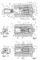
- the coupling represented in FIGS. 1 to 3 comprises a female element or socket A and a male element or end-piece B respectively connected to an upstream pipe C 1 and to a downstream pipe C 2 .
- the upstream pipe C 1 is, itself, connected to a source of fluid under pressure not shown.
- the element A belongs to a facility such as a service station and is connected by the pipe C 1 , which is flexible, to a tank of liquefied petroleum gas.
- the end B is, when it is mounted on a motor vehicle and connected to the fuel tank of the vehicle.
- the abutment B may be equipped with an internal shutter valve.
- the body 1 of the female element A is of generally cylindrical and circular shape, centered on an axis X A -X ' A which is also the longitudinal axis of a conduit 11 internal to the body 1 and in which is disposed a valve 2 movable along the axis X A -X ' A.
- the valve 2 is equipped with an O-ring 21 intended to bear against an internal shoulder 12 of the body 1, to seal the conduit 11.
- the valve 2 is provided with an external radial flange 22 on which a spring 3 in support against a second shoulder 13 of the body 1 exerts an elastic force F 3 closing the valve 2.
- the valve 2 is of cylindrical outer shape with a circular base centered on the axis X A -X ' A. It is provided with an axial bore 23 and several radial bores 24, two of which are visible in the figures.
- the valve 2 comprises a head 25 disposed in the duct 11, upstream of the shoulder 12. It also comprises a rod 26 disposed downstream of the shoulder 12 and which is noted 26a the end or "head” which protrudes relative to the flange 22 opposite the head 25.
- the body 2 is provided with a groove 14 for receiving an O-ring 15 against which the rod 26 bears.
- An operating sleeve 4 is disposed around the body 1 and resiliently loaded by a spring 5 to a position where it exerts on balls 6 a centripetal force. Only one ball is visible in the figures.
- the female element comprises several balls distributed around the axis X A- X ' A.
- the balls may be replaced by fingers or pawls ensuring, as the balls 6, a locking function of the male end in the fitted configuration shown in Figure 2.
- the body 101 of the male element B is of generally cylindrical and circular external shape centered on an axis X B -X ' B which is intended to be merged with the axis X A -X' A in a fitted configuration of the elements A and B.
- the body 101 defines a conduit 111 for circulating pressurized gas and is provided with a groove 116 for receiving balls 6 for the locking of elements A and B in a fitted configuration.
- the body 101 is also provided with an internal radial groove 117 which borders the end portion 111a of the conduit 111 closest to its outlet and in which is O-ring 102 is provided.
- This seal 102 is intended to provide effective insulation between the assembly consisting of conduits 11 and 111, on the one hand, and the ambient atmosphere, on the other hand, when elements A and B are coupled together. .
- the groove 117 is formed inside the body 101, so that the seal 102 is relatively protected from mechanical and chemical attack from outside.
- the head 26a of the rod 26 is provided with an external peripheral chamfer 26b whose angle at the apex ⁇ has a value of the order of 120 °.
- the angle ⁇ may have a value of between 60 and 175 °, preferably between 80 and 160 °, more preferably of the order of 120 °.
- angle ⁇ influences the deformation of the seal 102, its sealing and durability.
- An angle ⁇ of the order of 120 ° gives satisfactory results and allows to reconcile a free support of the head 26a on the seal 102, without degradation of the latter, with a clear opening of the valve 2.
- the length 26 of the end 26a is less than the sum of the distance d and the spacing e between the front face 118 of the element B and the flange 22, in the closed configuration of the valve.
- the invention has been shown when used in a motor vehicle tank filling station but may be employed in other fields where similar problems are likely to arise.
- the head or end 26a is integral with the head 25 and the stem 26 of the valve 2.
- this head can be attached to this rod and fixed by any appropriate means, in particular by gluing, screwing or welding .
- the head 26a may not be equipped with a chamfer such as that shown in the figures with reference 26b.
- the transition zone 26b between its front face 26c and its outer radial surface 26d is preferably rounded, with a radius of curvature R greater than 0.3 mm avoiding that the seal 102 is marked by the head 26a.
- the transition zone 26b is then in torus portion.
- the diameter of the rod 26 in the vicinity of the channels 24, that is to say in the vicinity of the shoulder 12 and the seal 15, is advantageously greater than the diameter of the head or end 26a.
- the result of the gas pressure in the coupled coupling tends to close the valve 2.
- the diameter of the rod 26 may be slightly greater than that of the head 26a, for example 0.2 mm.
Landscapes
- Engineering & Computer Science (AREA)
- General Engineering & Computer Science (AREA)
- Mechanical Engineering (AREA)
- Quick-Acting Or Multi-Walled Pipe Joints (AREA)
- Filling Or Discharging Of Gas Storage Vessels (AREA)
Applications Claiming Priority (2)
| Application Number | Priority Date | Filing Date | Title |
|---|---|---|---|
| FR0400753A FR2865522B1 (fr) | 2004-01-27 | 2004-01-27 | Element femelle de raccord, raccord rapide et installation de remplissage comprenant un tel element femelle |
| FR0400753 | 2004-01-27 |
Publications (2)
| Publication Number | Publication Date |
|---|---|
| EP1561991A1 EP1561991A1 (fr) | 2005-08-10 |
| EP1561991B1 true EP1561991B1 (fr) | 2007-04-18 |
Family
ID=34673880
Family Applications (1)
| Application Number | Title | Priority Date | Filing Date |
|---|---|---|---|
| EP05356017A Ceased EP1561991B1 (fr) | 2004-01-27 | 2005-01-26 | Elément femelle de raccord, raccord rapide et installation de remplissage comprenant un tel élément femelle |
Country Status (7)
| Country | Link |
|---|---|
| US (1) | US7195228B2 (enExample) |
| EP (1) | EP1561991B1 (enExample) |
| JP (1) | JP4881561B2 (enExample) |
| CN (1) | CN100445626C (enExample) |
| CA (1) | CA2492195C (enExample) |
| DE (1) | DE602005000888T2 (enExample) |
| FR (1) | FR2865522B1 (enExample) |
Cited By (1)
| Publication number | Priority date | Publication date | Assignee | Title |
|---|---|---|---|---|
| EP2728241A1 (de) | 2012-11-05 | 2014-05-07 | Magna Steyr Fahrzeugtechnik AG & Co KG | Tankstutzeneinheit mit Sperrventil |
Families Citing this family (39)
| Publication number | Priority date | Publication date | Assignee | Title |
|---|---|---|---|---|
| HK1077154A2 (en) | 2003-12-30 | 2006-02-03 | Icu Medical, Inc. | Valve assembly |
| US7998134B2 (en) | 2007-05-16 | 2011-08-16 | Icu Medical, Inc. | Medical connector |
| US20070088294A1 (en) | 2005-07-06 | 2007-04-19 | Fangrow Thomas F Jr | Medical connector with closeable male luer |
| AT502420B1 (de) * | 2005-09-09 | 2007-08-15 | Fronius Int Gmbh | Kupplungsvorrichtung für ein wasserdampf-schneidgerät |
| US8679090B2 (en) * | 2008-12-19 | 2014-03-25 | Icu Medical, Inc. | Medical connector with closeable luer connector |
| US9168366B2 (en) | 2008-12-19 | 2015-10-27 | Icu Medical, Inc. | Medical connector with closeable luer connector |
| FR2948435B1 (fr) * | 2009-07-23 | 2011-08-12 | Staubli Sa Ets | Element femelle de raccord et raccord rapide incorporant un tel element |
| FR2950950B1 (fr) * | 2009-10-01 | 2012-12-07 | Staubli Sa Ets | Element femelle de raccord rapide et raccord rapide incorporant un tel element |
| FR2950949B1 (fr) | 2009-10-01 | 2012-06-22 | Staubli Sa Ets | Element femelle de raccord rapide et raccord rapide incorporant un tel element |
| US8268252B2 (en) * | 2010-04-26 | 2012-09-18 | Geno Llc | Nitrosyl special connector |
| ES2493515T3 (es) | 2010-05-06 | 2014-09-11 | Icu Medical, Inc. | Conector médico con conexión tipo Luer obturable |
| US8267376B2 (en) * | 2010-05-27 | 2012-09-18 | International Engine Intellectual Property Company, Llc | Quick connect valve with integral backflow valve |
| US9739367B2 (en) * | 2011-07-14 | 2017-08-22 | Oetiker Ny, Inc. | Transmission anti-leak valve |
| CN103987423B (zh) | 2011-09-09 | 2018-04-13 | Icu医学有限公司 | 具有阻流配合界面的医用连接器 |
| US9664322B2 (en) * | 2012-06-21 | 2017-05-30 | Fiskars Oyj Abp | Quick connect and quick disconnect system male component |
| EP2920439B1 (en) | 2012-11-19 | 2017-07-26 | Castrol Limited | Apparatus and method |
| UA115574C2 (uk) | 2012-11-19 | 2017-11-27 | Кастрол Лімітед | Контейнер, спосіб і система керування |
| CN103196036B (zh) * | 2013-04-02 | 2014-10-29 | 力帆实业(集团)股份有限公司 | Cng充气阀转换接头 |
| ITMI20131866A1 (it) * | 2013-11-11 | 2015-05-12 | Stucchi Spa | Innesto a faccia piana per trasmissione fluidi con guarnizione frontale anulare. |
| CN103742741B (zh) * | 2014-01-13 | 2015-11-04 | 北京迈克芬科技有限公司 | 插座式快速断接器 |
| EP2944880B1 (en) * | 2014-05-16 | 2018-07-11 | Electrolux Appliances Aktiebolag | Gas-supply connection assembly, a method of connecting a gas supply line to a gas inlet port, and a gas cooking appliance |
| GB201409082D0 (en) | 2014-05-21 | 2014-07-02 | Castrol Ltd | Fluid container |
| US10619533B2 (en) | 2014-05-21 | 2020-04-14 | Castrol Limited | Fluid system and method |
| US20170114935A1 (en) | 2014-05-30 | 2017-04-27 | Jiffy-Tite Co., Inc. | Fluid connector with full insertion assurance cap disconnect tool |
| PL3149381T3 (pl) | 2014-05-30 | 2019-04-30 | Oetiker Ny Inc | Złącze dla płynu z nasadką zabezpieczającą całkowite wstawienie z pomocniczymi zatrzaskami |
| US10125908B2 (en) | 2015-02-18 | 2018-11-13 | Oetiker Ny, Inc. | Quick connect fluid coupling with integrated check valve |
| MX376638B (es) * | 2015-06-10 | 2025-03-07 | Stucchi Spa | Racor de unión rápida anti-destornillamiento. |
| JP6502776B2 (ja) * | 2015-07-24 | 2019-04-17 | 千住スプリンクラー株式会社 | スプリンクラーヘッド及び配管の接続構造 |
| FR3046209B1 (fr) * | 2015-12-23 | 2018-02-16 | Staubli Faverges | Element femelle de raccord rapide et raccord rapide comprenant un tel element femelle |
| DE102016110855A1 (de) * | 2016-06-14 | 2017-12-14 | Dr. Ing. H.C. F. Porsche Aktiengesellschaft | Druckhalteventil für ein reversibles Verbinden mit einer Luftleitung |
| CN107355619B (zh) * | 2017-08-09 | 2020-07-03 | 上海澳华光电内窥镜有限公司 | 一种连接器、内窥镜送水系统及内窥镜 |
| CN107300126A (zh) * | 2017-08-11 | 2017-10-27 | 天津安易达复合气瓶有限公司 | 一种非金属内胆复合气瓶的端部阀座 |
| CN109027666B (zh) * | 2018-09-30 | 2023-11-28 | 山东省计量科学研究院 | 一种气缸驱动式高压快装接头 |
| CN109114337B (zh) * | 2018-10-19 | 2020-06-09 | 贺雨鑫 | 同步式密封加注装置 |
| CN109404640A (zh) * | 2018-11-21 | 2019-03-01 | 重庆文理学院 | 一种空调检漏接头 |
| CN109538925A (zh) * | 2018-12-03 | 2019-03-29 | 海宁市英德赛电子有限公司 | 高纯氨槽车自动化充装系统 |
| US11274778B2 (en) | 2018-12-12 | 2022-03-15 | International Business Machines Corporation | Couplings with engagement monitor |
| USD1105422S1 (en) | 2024-02-09 | 2025-12-09 | Icu Medical, Inc. | Medical connector cover |
| CN119142554B (zh) * | 2024-11-20 | 2025-04-01 | 遨天科技(北京)有限公司 | 一种霍尔电推进用加排阀及构件 |
Family Cites Families (17)
| Publication number | Priority date | Publication date | Assignee | Title |
|---|---|---|---|---|
| GB732186A (en) * | 1952-06-06 | 1955-06-22 | Scandinavian Agencies Corp Ltd | Improvements relating to conduit couplings |
| JPS5134023Y1 (enExample) * | 1970-07-07 | 1976-08-23 | ||
| US3715099A (en) * | 1971-06-02 | 1973-02-06 | Crawford Fitting Co | Valved quick-disconnect coupling |
| DE2558650A1 (de) * | 1975-12-24 | 1977-07-07 | Klein Rectus App | Selbstabsperrende schnellkupplung fuer gas- oder fluessigkeitsfuehrende leitungen |
| US4613112A (en) * | 1985-07-19 | 1986-09-23 | Essex Industries, Inc. | Quick-disconnect fitting for gas line connection |
| JP2752087B2 (ja) * | 1988-06-30 | 1998-05-18 | 株式会社東芝 | 自動取引装置 |
| JPH0212591U (enExample) * | 1988-07-11 | 1990-01-25 | ||
| SE470452B (sv) * | 1992-10-16 | 1994-04-11 | Bjoern Engdahl | Slangkoppling för tryckluft med don för tryckavlastning vid isärkoppling |
| FR2719105B1 (fr) * | 1994-04-21 | 1996-05-31 | Yto | Coupleur rapide pour conduit sous pression à désaccouplement contrôlé. |
| DE29500808U1 (de) * | 1995-01-19 | 1995-03-16 | Weh Gmbh, Verbindungstechnik, 89257 Illertissen | Schnellanschlußkupplung |
| FR2740197B1 (fr) * | 1995-10-20 | 1997-12-26 | Yto | Coupleur rapide a desaccouplement a deux phases |
| US5577706A (en) * | 1995-10-25 | 1996-11-26 | King; Robert J. | Water faucet with automatic shut-off mechanism for water conservation |
| CN2268171Y (zh) * | 1996-10-21 | 1997-11-19 | 陈旭 | 方便快速接头 |
| US5967491A (en) * | 1997-12-01 | 1999-10-19 | Parker-Hannifin Corporation | Anti-leak quick action coupler |
| FR2831940B1 (fr) * | 2001-11-06 | 2006-09-29 | Staubli Sa Ets | Raccord rapide pour la jonction amovible de deux canalisations |
| US6691978B1 (en) * | 2002-08-21 | 2004-02-17 | Gaap Gas Controls Llc | Cylinder coupling device |
| US6767002B2 (en) * | 2002-11-06 | 2004-07-27 | Torrent Trading Ltd. | Check valve |
-
2004
- 2004-01-27 FR FR0400753A patent/FR2865522B1/fr not_active Expired - Fee Related
-
2005
- 2005-01-12 CA CA2492195A patent/CA2492195C/fr not_active Expired - Fee Related
- 2005-01-12 CN CNB2005100020203A patent/CN100445626C/zh not_active Expired - Fee Related
- 2005-01-19 US US11/037,189 patent/US7195228B2/en not_active Expired - Fee Related
- 2005-01-20 JP JP2005012429A patent/JP4881561B2/ja not_active Expired - Fee Related
- 2005-01-26 DE DE602005000888T patent/DE602005000888T2/de not_active Expired - Lifetime
- 2005-01-26 EP EP05356017A patent/EP1561991B1/fr not_active Ceased
Cited By (2)
| Publication number | Priority date | Publication date | Assignee | Title |
|---|---|---|---|---|
| EP2728241A1 (de) | 2012-11-05 | 2014-05-07 | Magna Steyr Fahrzeugtechnik AG & Co KG | Tankstutzeneinheit mit Sperrventil |
| US9579970B2 (en) | 2012-11-05 | 2017-02-28 | Magna Steyr Fahrzeugtechnik Ag & Co Kg | Filler neck assembly with stop valve |
Also Published As
| Publication number | Publication date |
|---|---|
| CN100445626C (zh) | 2008-12-24 |
| US20050161628A1 (en) | 2005-07-28 |
| CN1648510A (zh) | 2005-08-03 |
| EP1561991A1 (fr) | 2005-08-10 |
| CA2492195A1 (fr) | 2005-07-27 |
| JP4881561B2 (ja) | 2012-02-22 |
| FR2865522A1 (fr) | 2005-07-29 |
| JP2005214414A (ja) | 2005-08-11 |
| US7195228B2 (en) | 2007-03-27 |
| FR2865522B1 (fr) | 2006-03-03 |
| DE602005000888T2 (de) | 2008-01-17 |
| CA2492195C (fr) | 2012-12-18 |
| DE602005000888D1 (de) | 2007-05-31 |
Similar Documents
| Publication | Publication Date | Title |
|---|---|---|
| EP1561991B1 (fr) | Elément femelle de raccord, raccord rapide et installation de remplissage comprenant un tel élément femelle | |
| EP1308663B1 (fr) | Raccord rapide pour la jonction amovible de deux canalisations | |
| EP1422462B1 (fr) | Raccord rapide muni d'un dispositif de surpression intégré | |
| EP2020555B1 (fr) | Elément de raccord rapide et raccord rapide comprenant un tel élément | |
| EP2778495B1 (fr) | Elément femelle et raccord destines à réaliser la jonction amovible de deux canalisations de fluide | |
| EP2074342B1 (fr) | Robinet, notamment pour bouteille de gaz ultra-haute pureté | |
| EP2771598B1 (fr) | Robinet d'isolement | |
| CA2484531C (fr) | Element femelle de raccord et raccord rapide incorporant un tel element | |
| FR2865259A1 (fr) | Raccord rapide et procede de desacouplement des elements male et femelle d'un tel raccord | |
| EP1526318A1 (fr) | Raccord rapide pour la jonction amovible de deux canalisations et utilisation d'un tel raccord | |
| FR2835585A1 (fr) | Raccord rapide pour la jonction amovible de deux canalisations | |
| EP1422461A1 (fr) | Raccord rapide pour la jonction amovible de deux canalisations | |
| FR2934342A3 (fr) | Dispositif de commande hydraulique d'embrayage et embrayage correspondant. | |
| FR3046209A1 (fr) | Element femelle de raccord rapide et raccord rapide comprenant un tel element femelle | |
| EP1561988A1 (fr) | Raccord à couplage instantané | |
| EP4108968B1 (fr) | Dispositif de raccordement fluidique avec vanne inserable anti-retour pour vehicule | |
| EP4108964B1 (fr) | Vanne inserable anti-retour pour vehicule | |
| EP4416418B1 (fr) | Dispositif de raccordement d'un tube | |
| FR2938038A1 (fr) | Element d'etancheite sans zone de retention et dispositif de raccordement comportant un tel element d'etancheite | |
| FR3000133A1 (fr) | Ligne d'echappement de vehicule automobile comportant une rotule perfectionnee | |
| FR3052528A1 (fr) | Vanne anti-retour et circuit et dispositif de refroidissement pour un vehicule comportant une telle vanne | |
| FR2860853A1 (fr) | Dispositif de raccordement etanche d'un tube a nez tubulaire filete | |
| FR2862368A1 (fr) | Piquage, circuit pneumatique equipe d'un tel piquage et ensemble comprenant un tel circuit | |
| EP4227566B1 (fr) | Elément femelle de raccord fluidique et raccord fluidique comprenant un tel élément | |
| EP3985295A1 (fr) | Dispositif de raccordement fluidique de type cartouche |
Legal Events
| Date | Code | Title | Description |
|---|---|---|---|
| PUAI | Public reference made under article 153(3) epc to a published international application that has entered the european phase |
Free format text: ORIGINAL CODE: 0009012 |
|
| AK | Designated contracting states |
Kind code of ref document: A1 Designated state(s): AT BE BG CH CY CZ DE DK EE ES FI FR GB GR HU IE IS IT LI LT LU MC NL PL PT RO SE SI SK TR |
|
| AX | Request for extension of the european patent |
Extension state: AL BA HR LV MK YU |
|
| 17P | Request for examination filed |
Effective date: 20051203 |
|
| AKX | Designation fees paid |
Designated state(s): CH DE FR GB IT LI NL |
|
| 17Q | First examination report despatched |
Effective date: 20060719 |
|
| GRAP | Despatch of communication of intention to grant a patent |
Free format text: ORIGINAL CODE: EPIDOSNIGR1 |
|
| GRAS | Grant fee paid |
Free format text: ORIGINAL CODE: EPIDOSNIGR3 |
|
| GRAA | (expected) grant |
Free format text: ORIGINAL CODE: 0009210 |
|
| AK | Designated contracting states |
Kind code of ref document: B1 Designated state(s): CH DE FR GB IT LI NL |
|
| REG | Reference to a national code |
Ref country code: CH Ref legal event code: EP |
|
| GBT | Gb: translation of ep patent filed (gb section 77(6)(a)/1977) |
Effective date: 20070508 |
|
| REF | Corresponds to: |
Ref document number: 602005000888 Country of ref document: DE Date of ref document: 20070531 Kind code of ref document: P |
|
| PLBE | No opposition filed within time limit |
Free format text: ORIGINAL CODE: 0009261 |
|
| STAA | Information on the status of an ep patent application or granted ep patent |
Free format text: STATUS: NO OPPOSITION FILED WITHIN TIME LIMIT |
|
| 26N | No opposition filed |
Effective date: 20080121 |
|
| REG | Reference to a national code |
Ref country code: DE Ref legal event code: R082 Ref document number: 602005000888 Country of ref document: DE Representative=s name: PFENNING, MEINIG & PARTNER MBB PATENTANWAELTE, DE |
|
| REG | Reference to a national code |
Ref country code: FR Ref legal event code: PLFP Year of fee payment: 12 |
|
| REG | Reference to a national code |
Ref country code: FR Ref legal event code: PLFP Year of fee payment: 13 |
|
| PGFP | Annual fee paid to national office [announced via postgrant information from national office to epo] |
Ref country code: NL Payment date: 20170126 Year of fee payment: 13 |
|
| PGFP | Annual fee paid to national office [announced via postgrant information from national office to epo] |
Ref country code: CH Payment date: 20170127 Year of fee payment: 13 Ref country code: DE Payment date: 20170125 Year of fee payment: 13 |
|
| PGFP | Annual fee paid to national office [announced via postgrant information from national office to epo] |
Ref country code: GB Payment date: 20170127 Year of fee payment: 13 |
|
| PGFP | Annual fee paid to national office [announced via postgrant information from national office to epo] |
Ref country code: IT Payment date: 20170124 Year of fee payment: 13 |
|
| REG | Reference to a national code |
Ref country code: FR Ref legal event code: PLFP Year of fee payment: 14 |
|
| REG | Reference to a national code |
Ref country code: DE Ref legal event code: R119 Ref document number: 602005000888 Country of ref document: DE |
|
| REG | Reference to a national code |
Ref country code: CH Ref legal event code: PL |
|
| REG | Reference to a national code |
Ref country code: NL Ref legal event code: MM Effective date: 20180201 |
|
| GBPC | Gb: european patent ceased through non-payment of renewal fee |
Effective date: 20180126 |
|
| PG25 | Lapsed in a contracting state [announced via postgrant information from national office to epo] |
Ref country code: DE Free format text: LAPSE BECAUSE OF NON-PAYMENT OF DUE FEES Effective date: 20180801 |
|
| PG25 | Lapsed in a contracting state [announced via postgrant information from national office to epo] |
Ref country code: CH Free format text: LAPSE BECAUSE OF NON-PAYMENT OF DUE FEES Effective date: 20180131 Ref country code: GB Free format text: LAPSE BECAUSE OF NON-PAYMENT OF DUE FEES Effective date: 20180126 Ref country code: NL Free format text: LAPSE BECAUSE OF NON-PAYMENT OF DUE FEES Effective date: 20180201 Ref country code: LI Free format text: LAPSE BECAUSE OF NON-PAYMENT OF DUE FEES Effective date: 20180131 |
|
| PG25 | Lapsed in a contracting state [announced via postgrant information from national office to epo] |
Ref country code: IT Free format text: LAPSE BECAUSE OF NON-PAYMENT OF DUE FEES Effective date: 20180126 |
|
| PGFP | Annual fee paid to national office [announced via postgrant information from national office to epo] |
Ref country code: FR Payment date: 20230125 Year of fee payment: 19 |
|
| PG25 | Lapsed in a contracting state [announced via postgrant information from national office to epo] |
Ref country code: FR Free format text: LAPSE BECAUSE OF NON-PAYMENT OF DUE FEES Effective date: 20240131 |
|
| PG25 | Lapsed in a contracting state [announced via postgrant information from national office to epo] |
Ref country code: FR Free format text: LAPSE BECAUSE OF NON-PAYMENT OF DUE FEES Effective date: 20240131 |