EP1561634A2 - Supply system - Google Patents
Supply system Download PDFInfo
- Publication number
- EP1561634A2 EP1561634A2 EP05002330A EP05002330A EP1561634A2 EP 1561634 A2 EP1561634 A2 EP 1561634A2 EP 05002330 A EP05002330 A EP 05002330A EP 05002330 A EP05002330 A EP 05002330A EP 1561634 A2 EP1561634 A2 EP 1561634A2
- Authority
- EP
- European Patent Office
- Prior art keywords
- supply system
- pressure
- seat unit
- seat
- unit
- Prior art date
- Legal status (The legal status is an assumption and is not a legal conclusion. Google has not performed a legal analysis and makes no representation as to the accuracy of the status listed.)
- Granted
Links
Images


Classifications
-
- B—PERFORMING OPERATIONS; TRANSPORTING
- B60—VEHICLES IN GENERAL
- B60N—SEATS SPECIALLY ADAPTED FOR VEHICLES; VEHICLE PASSENGER ACCOMMODATION NOT OTHERWISE PROVIDED FOR
- B60N2/00—Seats specially adapted for vehicles; Arrangement or mounting of seats in vehicles
- B60N2/90—Details or parts not otherwise provided for
- B60N2/914—Hydro-pneumatic adjustments of the shape
Definitions
- the invention relates to a supply system for an inflatable seat unit of a motor vehicle, the at least having a module in a position of use with a fluid, in particular with air, is filled and in one Non-use position is fluidless.
- a device for automatic adjustment of the comfort of a motor vehicle seat described.
- This device has several in Motor vehicle seat arranged fluid-filled bases and a fluid pressure adjustment system for the passage of a fluid in selected bubbles of the bubbles in or out of these to set out.
- the device has a Pressure transducer to fluid pressure within the fluid pressure adjustment system at least one corresponding pressure signal reshape, and a controller to the pressure signal to receive and the information about the dimension of the occupant the seat as a function of the received pressure signal estimate.
- One of the disadvantages of this known device is that by pivoting and / or moving the backrest part and / or the seat part of the motor vehicle seat in a non-use position the seat despite fluidless Blowing takes up so much space inside the motor vehicle, whereby the loading volume of the motor vehicle considerably restricted is. Furthermore, the supply system to Setting the comfort of the motor vehicle seat no easy Structure, which is especially for the installation effort has a negative effect.
- the module comprises a sheath in which a foam and a reinforcing element are arranged, which the foam in non-use at least partially absorbs.
- the Seat unit that includes a pressure sensor is with a Inlet valve having inlet line and with a connected to an outlet valve having discharge line.
- the depression Can be adjusted according to the contour of the foam be the foam in the use position of the inflatable Seat unit occupies.
- the contour of the depression can, for example formed mirror-shaped to the contour of the foam be.
- the evacuated module takes a flat Contour on the surface, so that the seat unit in Non-use position characterized by a compact arrangement.
- the seat unit according to the invention as Seat part and / or as a backrest part of a motor vehicle seat formed, wherein in the use position, i. if air with one certain pressure is inside the module, the Foam a three-dimensional shape (concave) accordingly the design or styling requirements for seats.
- the inflatable Seat unit has several modules on the backrest part as well can be arranged on the seat part. According to the requirements the modules can be different three-dimensional Take forms, which in particular by the used Foam within the envelope of each module achieved becomes.
- the air inflow process can be started.
- the inlet valve is opened and air can enter the Seat unit, in particular in each module, inflow. Is the If ambient pressure within the module is reached, this closes Supply system the inlet valve.
- the pressure sensor on the seat unit is arranged, this checks the inside of the module present air pressure.
- the evacuation process air outflow from the seat unit
- This is at the outflow line preferably arranged a vacuum pump.
- Vacuum pump generates a negative pressure in the outflow line, the seat unit after opening the exhaust valve, especially every module, collapses. Im evacuated Condition, the seat unit is significantly reduced in terms of volume, creating a large cargo area within the vehicle arises.
- the supply system can be designed with a compressor be.
- the compressor can in this case on the inflow line be arranged.
- the seat unit is preferably over a Pressure reducer unit, for example, be a throttle can, connected to the compressor.
- the used compressor accelerates the filling of the inflatable seat unit, in particular the individual modules.
- a defined pressure, above the ambient pressure, below Use of the pressure reducer unit can be preset. This ensures that the seat unit according to the invention is not loaded with too high a pressure, which in the worst case the seat unit could be destroyed.
- the seating comfort the inflatable seat unit ensures on the other hand an overload of the same prevented.
- the supply system has a ventilation unit, in particular a vent valve, on, for example, on the inflow line is arranged.
- the bleed valve this can be the supply system for security reasons depressurize, which is performed, for example, if the motor vehicle is locked or not in the Operating state is located.
- the throttle used can be mechanical be adjustable.
- Pressure reducer units can be used within the supply system.
- the inventive Supply system a combined compressor / vacuum pump which, in particular, achieves package advantages become.
- the stored inside the pressure tank Air can, for example, via the pressure reducer unit be directed into the inflatable seat unit.
- One of Advantages of arranging a pressure tank within this Inventive supply system is that the inflow the air into the respective modules of the seat unit takes place under a significant noise reduction.
- the Combined compressor / vacuum pump for example, only then be activated when a certain supply pressure is exceeded or exceeded. By means of the provided Volumes in the pressure tank and / or vacuum tank are several Cycles without pump support possible.
- the seat unit may be sensible to use the seat unit with one to connect additional drain valve.
- the seat unit in particular the modules with an elevated Air pressure applied, for example, over 1.3 Bar can be a quick evacuation via the drain valve respectively.
- the vacuum tank be designed smaller in terms of its volume can.
- FIG. 1 shows an embodiment of a supply system, which is an inflatable seat unit 1, as exemplified in Fig.5, with a fluid, in particular with air, supplied.
- the inflatable Seat unit 1 a seat part 19 and a backrest part 20, the each equipped with individual modules 2 (air chambers) are. These modules 2 are filled with air in a position of use and in a non-use position fluidless.
- the backrest part 20 is here with a pressure sensor 3 and the seat part 19 connected to a pressure sensor 21. Via an inflow line 8, the seat part 19 and the backrest part 20th be supplied with air.
- the inflow line 8 has in present embodiment in front of the seat part 19 and in front of the backrest part 20 in each case an inlet valve 7, 22.
- Button unit By pressing another, not shown Button unit can evacuate the air from the seat unit 1 to be started.
- the exhaust valves 9, 23 open, at the same time the vacuum pump 11 is a negative pressure forms within the outflow line 10 and thus the seat unit 1 deprives the air.
- the inflatable seat unit 1 forms these in the present Invention a flat cargo area.
- the inlet area the inflow line 8 and the outlet of the outflow line 10 are in the present embodiments the invention equipped with a filter 24. hereby is the purpose that no dust or foreign bodies in the Supply system or get into the individual modules 2.
- the filter 124 also works as a muffler.
- self-inflatable seat unit 1 has only one within the modules 2 Air pressure that corresponds substantially to the ambient pressure.
- a compressor unit 12 at the Inflow line 8 are arranged.
- Pressure reducing unit 13 in the form of a throttle between the Compressor 12 and the seat part 19 and the backrest part 20 are arranged.
- a vent valve 14 is provided between the pressure-reducing unit 13 and the compressor 12.
- the intake valves are 7, 22, wherein the compressor 12 through the inflow line 8 via the pressure reducer 13 air with a certain Pressure in the modules 2 promoted. Is the desired Pressure reached within the individual modules 2, switches the compressor 12 from.
- the desired pressure within the Module 2 for example, by a mechanical adjustable Throttle can be set as a pressure reducer unit 13.
- Alternative pressure reducer units 13 are also within This supply system can be used. About opening the Bleed valve 14 switches the supply system for safety reasons the inflow line 8 depressurized.
- FIG. 3 and 4 show further alternatives of the invention Supply system, below only to discuss the differences.
- a combined compressor / vacuum pump 15 arranged, both via the inflow 8 air with a certain Pressure in the inflatable seat unit 1 can convey as also during the evacuation process air from the individual Pumps out modules 2 via the outflow line 10.
- a combined compressor / vacuum pump 15 conditions a control of the airways.
- four valves 25, 26, 27, 28 arranged on the supply system.
- the valves 26, 27 are open and the valves 25 and 28 closed.
- a pressure tank sensor 29th and a vacuum tank sensor 30 is disposed on the vacuum tank 17. through these pressure sensors 29, 30 can on the over- or on the negative pressure side, the supply pressures in a defined Pressure windows are regulated.
- the supply system can according to Figure 3, the seat part 19 and the backrest part 20 optional via the pressure tank 16 and / or via the combined Supply compressor vacuum pump 15.
- the evacuation process can according to the vacuum tank 17 and / or over the Combined compressor / vacuum pump 15 done.
- the compressor / vacuum pump 15 for example, below the vehicle floor to be ordered.
- the vacuum tank 17 and the Pressure tank 16 are further at various points of the motor vehicle arranged.
- the vacuum tank 17 may, for example functionally integrated to form a vehicle seat console.
- Fig. 4 is essentially a supply system shown in FIG. The difference, however, is that both the seat part 19 and the backrest part 20 with a drain valve 18 are connected. By opening the drain valve 18 may be a faster evacuation of the seat unit 1, in particular the individual modules 2, take place. Here flows the Air from the individual modules 2 via the drain valve 18 in the environment.
- a smaller volume-shaped one Vacuum tank 17 can be used as in Figure 3.
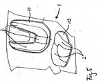
- FIG. 6 shows a sectional view of the inflatable Seat unit 1, which is fixed to a support element 31.
- the support member 31 is inclined at a certain angle aligned and exemplifies the backrest part 20 of a Motor vehicle seat dar.
- Figure 4 includes the seat unit 1 several modules 2, into the air can be routed to one Position of use, that means a desired seat or to get a leaning surface. If the room is inside the Motor vehicle to be used elsewhere, for example For a transport, the air is removed from the inflatable Seat unit 1, in particular taken from all modules 2, so that the inflatable seat unit 1 in non-use position of Seat 1 occupies a minimum volume.
- the module 2 has 6 a sheath 4, which in the present embodiment a plastic film is.
- the enclosure 4 thus comprises the Reinforcing element 6 and the foam 5.
- the reinforcing element 6 is further with wells that are not are shown formed, in which the foam 5 in Non-use position, i. when the air from the inventive Seat unit 1 is completely evacuated, at least partially recorded.
- the foam In position of use, the foam has 5 a three-dimensional shape (concave) on.
- the geometric Shape of the depression according to the invention of this three-dimensional Adapted form so that in the evacuated state the shape of the foam 5 reliably from or from the Wells can be included.
- On the outside of the Envelope 4 is a fabric 32, the edge of the panel fixed by a screw 33 is.
- the reinforcing element 6 is provided with a first side 34 and a second side 35, wherein the second side 35 facing away from the foam 5.
- the foam 5 is in the illustrated embodiment on the inner wall of the Enclosed 4 glued.
- the second side 35 of the reinforcing element 6 is further bonded to the enclosure 4.
- Other Connection options are of course conceivable.
- To control the pressure within the respective Module 2 may include a controller (not shown) be that the necessary pressure distribution via control valves regulates.
- the controller can control the pressure within the modules 2 are controlled so that the comfort, for example depending on the weight or driving situation can.
- the controller can control the pressure within the modules 2 are controlled so that the comfort, for example depending on the weight or driving situation can.
- the controller pressure variations in the individual modules 2 causes to be prevented.
- the envelope 4 is formed as a film made of plastic, especially made of polyurethane.
- the film 4 can this elastic or less elastic properties exhibit.
- the second side 35 of the reinforcing element 6 in this case lies directly on the casing 4, wherein the first side 34 facing the foam 5.
- the foam 5 is open-pored so that When evacuating the respective module 2, the air as possible quickly from the hollow chambers or pores of the foam. 5 can escape.
Abstract
Description
Die Erfindung betrifft ein Versorgungssystem für eine aufblasbare Sitzeinheit eines Kraftfahrzeuges, die mindestens ein Modul aufweist, das in einer Gebrauchslage mit einem Fluid, insbesondere mit Luft, gefüllt ist und in einer Nichtgebrauchslage fluidlos ist.The invention relates to a supply system for an inflatable seat unit of a motor vehicle, the at least having a module in a position of use with a fluid, in particular with air, is filled and in one Non-use position is fluidless.
Gemäß der DE 198 06 535 C2 ist eine Vorrichtung zum automatischen Einstellen des Komforts eines Kraftfahrzeugsitzes beschrieben. Diese Vorrichtung weist hierbei mehrere im Kraftfahrzeugsitz angeordnete fluidfüllbare Basen auf sowie ein Fluiddruckeinstellungssystem, um den Durchgang eines Fluids in ausgewählten Blasen der Blasen hinein oder aus diesen heraus einzustellen. Des Weiteren weist die Vorrichtung einen Druckumformer auf, um Fluidruck innerhalb des Fluiddruckeinstellungssystems um mindestens ein entsprechendes Drucksignal umzuformen, und einen Controller, um das Drucksignal zu empfangen und die Information über die Abmessung des Insassen des Sitzes als eine Funktion des empfangenen Drucksignals abzuschätzen. Einer der Nachteile dieser bekannten Vorrichtung ist, dass durch ein Verschwenken und/oder Verschieben des Lehnenteils und/oder des Sitzteils des Kraftfahrzeugsitzes in eine Nichtgebrauchslage der Sitz trotz fluidloser Blasen soviel Platz innerhalb des Kraftfahrzeuges einnimmt, wodurch das Ladevolumen des Kraftfahrzeuges erheblich eingeschränkt ist. Des Weiteren weist das Versorgungssystem zum Einstellen des Komforts des Kraftfahrzeugsitzes keinen einfachen Aufbau auf, welches sich insbesondere für den Montageaufwand negativ auswirkt.According to DE 198 06 535 C2, a device for automatic adjustment of the comfort of a motor vehicle seat described. This device has several in Motor vehicle seat arranged fluid-filled bases and a fluid pressure adjustment system for the passage of a fluid in selected bubbles of the bubbles in or out of these to set out. Furthermore, the device has a Pressure transducer to fluid pressure within the fluid pressure adjustment system at least one corresponding pressure signal reshape, and a controller to the pressure signal to receive and the information about the dimension of the occupant the seat as a function of the received pressure signal estimate. One of the disadvantages of this known device is that by pivoting and / or moving the backrest part and / or the seat part of the motor vehicle seat in a non-use position the seat despite fluidless Blowing takes up so much space inside the motor vehicle, whereby the loading volume of the motor vehicle considerably restricted is. Furthermore, the supply system to Setting the comfort of the motor vehicle seat no easy Structure, which is especially for the installation effort has a negative effect.
Zum allgemeinen technischen Verständnis wird noch auf die US 38 04 848 und DE 299 24 138 U1 verwiesen.The general technical understanding is still to the US 38 04 848 and DE 299 24 138 U1 referenced.
Es ist Aufgabe der vorliegenden Erfindung, ein Versorgungssystem für eine aufblasbare Sitzeinheit bereitzustellen, mit der die obengenannten Nachteile vermieden werden, insbesondere ein einfaches und kostengünstiges Versorgungssystem geschaffen wird.It is an object of the present invention to provide a supply system to provide for an inflatable seat unit, with which the abovementioned disadvantages are avoided, in particular a simple and inexpensive supply system is created.
Die Aufgabe wird durch ein Versorgungssystem mit
den Merkmalen des Anspruchs 1 gelöst. In den abhängigen Ansprüchen
sind vorteilhafte Weiterbildungen des erfindungsgemäßen
Versorgungssystems angegeben.The task is through a supply system with
the features of
Es ist erfindungsgemäß vorgesehen, dass das Modul (Kammer) eine Umhüllung umfasst, in der ein Schaumstoff und ein Verstärkungselement angeordnet sind, welches den Schaumstoff in Nichtgebrauchslage zumindest teilweise aufnimmt. Die Sitzeinheit, die einen Drucksensor umfasst, ist mit einer ein Einlassventil aufweisenden Einströmungsleitung und mit einer ein Auslassventil aufweisende Ausströmungsleitung verbunden. Wird die Luft aus der aufblasbaren Sitzeinheit evakuiert, erreicht das Modul nach einer festgelegten Zeit die Nichtgebrauchslage, wobei sich der Schaumstoff zumindest teilweise in das Verstärkungselement, welches mit einer oder mehreren Vertiefung ausgebildet sein kann, zurückzieht. Die Vertiefung kann entsprechend der Kontur des Schaumstoffes angepasst sein, die der Schaumstoff in Gebrauchslage der aufblasbaren Sitzeinheit einnimmt. Die Kontur der Vertiefung kann beispielsweise spiegelförmig zur Kontur des Schaumstoffes gebildet sein. Vorzugsweise nimmt das evakuierte Modul eine flache Kontur an der Oberfläche ein, so dass sich die Sitzeinheit in Nichtgebrauchslage durch eine kompakte Anordnung auszeichnet. Zweckmäßigerweise ist die erfindungsgemäße Sitzeinheit als Sitzteil und/oder als Lehnenteil eines Kraftfahrzeugsitzes ausgebildet, wobei in Gebrauchslage, d.h. wenn Luft mit einem bestimmten Druck sich innerhalb des Moduls befindet, der Schaumstoff eine dreidimensionale Form (konkav) entsprechend den Design- oder Stylingvorgaben für Sitze aufweist. In einer bevorzugten Ausführungsform der Erfindung weist die aufblasbare Sitzeinheit mehrere Module auf, die am Lehnenteil sowie am Sitzteil angeordnet sein können. Entsprechend den Anforderungen können die Module unterschiedliche dreidimensionale Formen annehmen, welches insbesondere durch den eingesetzten Schaumstoff innerhalb der Umhüllung des jeweiligen Moduls erzielt wird. Durch beispielsweise eine Betätigung einer Tasteinheit kann der Lufteinströmvorgang gestartet werden. Hierbei wird das Einlassventil geöffnet und Luft kann in die Sitzeinheit, insbesondere in jedes Modul, einströmen. Ist der Umgebungsdruck innerhalb des Moduls erreicht, schließt das Versorgungssystem das Einlassventil. Der Drucksensor, der an der Sitzeinheit angeordnet ist, überprüft hierbei den innerhalb des Moduls vorliegenden Luftdruck.It is inventively provided that the module (Chamber) comprises a sheath in which a foam and a reinforcing element are arranged, which the foam in non-use at least partially absorbs. The Seat unit that includes a pressure sensor is with a Inlet valve having inlet line and with a connected to an outlet valve having discharge line. When the air is evacuated from the inflatable seat unit the module after a specified time the non-use position, wherein the foam is at least partially in the reinforcing element, which with one or more Well can be formed, withdraws. The depression Can be adjusted according to the contour of the foam be the foam in the use position of the inflatable Seat unit occupies. The contour of the depression can, for example formed mirror-shaped to the contour of the foam be. Preferably, the evacuated module takes a flat Contour on the surface, so that the seat unit in Non-use position characterized by a compact arrangement. Conveniently, the seat unit according to the invention as Seat part and / or as a backrest part of a motor vehicle seat formed, wherein in the use position, i. if air with one certain pressure is inside the module, the Foam a three-dimensional shape (concave) accordingly the design or styling requirements for seats. In a preferred embodiment of the invention comprises the inflatable Seat unit has several modules on the backrest part as well can be arranged on the seat part. According to the requirements the modules can be different three-dimensional Take forms, which in particular by the used Foam within the envelope of each module achieved becomes. For example, by pressing a button unit the air inflow process can be started. in this connection the inlet valve is opened and air can enter the Seat unit, in particular in each module, inflow. Is the If ambient pressure within the module is reached, this closes Supply system the inlet valve. The pressure sensor on the seat unit is arranged, this checks the inside of the module present air pressure.
Der Evakuierungsvorgang (Luftausströmvorgang aus der Sitzeinheit) kann beispielsweise durch eine Betätigung einer weiteren Tasteinheit initiiert werden. Hierbei ist an der Ausströmungsleitung vorzugsweise eine Vakuumpumpe angeordnet. Diese Vakuumpumpe erzeugt einen Unterdruck in der Ausströmungsleitung, der nach Öffnen des Auslassventils die Sitzeinheit, insbesondere jedes Modul, kollabieren lässt. Im evakuierten Zustand ist die Sitzeinheit volumenmäßig erheblich reduziert, wodurch eine große Ladefläche innerhalb des Kraftfahrzeuges entsteht.The evacuation process (air outflow from the seat unit) For example, by pressing another Button unit to be initiated. This is at the outflow line preferably arranged a vacuum pump. These Vacuum pump generates a negative pressure in the outflow line, the seat unit after opening the exhaust valve, especially every module, collapses. Im evacuated Condition, the seat unit is significantly reduced in terms of volume, creating a large cargo area within the vehicle arises.
In einer weiteren Ausführungsform der Erfindung kann das Versorgungssystem mit einem Kompressor ausgebildet sein. Der Kompressor kann hierbei an der Einströmungsleitung angeordnet sein. Die Sitzeinheit ist vorzugsweise über eine Druckmindereinheit, die beispielsweise eine Drossel sein kann, mit dem Kompressor verbunden. Der eingesetzte Kompressor beschleunigt hierbei das Füllen der aufblasbaren Sitzeinheit, insbesondere der einzelnen Module. Des Weiteren kann ein definierter Druck, oberhalb des Umgebungsdruckes, unter Verwendung der Druckmindereinheit voreingestellt werden. Hierdurch wird erreicht, dass die erfindungsgemäße Sitzeinheit nicht mit einem zu hohen Druck belastet wird, wodurch schlimmstenfalls die Sitzeinheit zerstört werden könnte. Durch eine derartige Ausgestaltung wird einerseits der Sitzkomfort der aufblasbaren Sitzeinheit gewährleistet andererseits eine Überlastung derselben vorgebeugt. Zweckmäßigerweise weist das Versorgungssystem eine Entlüftungseinheit, insbesondere ein Entlüftungsventil, auf, das beispielsweise an der Einströmungsleitung angeordnet ist. Das Entlüftungsventil kann hierbei das Versorgungssystem aus Sicherheitsgründen drucklos schalten, welches beispielsweise durchgeführt wird, wenn das Kraftfahrzeug verschlossen ist bzw. sich nicht im Betriebszustand befindet. In einer Ausführungsform der Erfindung kann die verwendete Drossel beispielsweise mechanisch einstellbar sein. Es sind selbstverständlich alternative Druckmindereinheiten innerhalb des Versorgungssystem einsetzbar.In a further embodiment of the invention The supply system can be designed with a compressor be. The compressor can in this case on the inflow line be arranged. The seat unit is preferably over a Pressure reducer unit, for example, be a throttle can, connected to the compressor. The used compressor accelerates the filling of the inflatable seat unit, in particular the individual modules. Furthermore, can a defined pressure, above the ambient pressure, below Use of the pressure reducer unit can be preset. This ensures that the seat unit according to the invention is not loaded with too high a pressure, which in the worst case the seat unit could be destroyed. By such a configuration, on the one hand, the seating comfort the inflatable seat unit ensures on the other hand an overload of the same prevented. Conveniently, the supply system has a ventilation unit, in particular a vent valve, on, for example, on the inflow line is arranged. The bleed valve this can be the supply system for security reasons depressurize, which is performed, for example, if the motor vehicle is locked or not in the Operating state is located. In one embodiment of the invention For example, the throttle used can be mechanical be adjustable. Of course they are alternative Pressure reducer units can be used within the supply system.
In einer weiteren Ausführungsform der Erfindung weist das erfindungsgemäße Versorgungssystem eine kombinierte Kompressor-/Vakuumpumpe auf, wodurch insbesondere Package-Vorteile erzielt werden. Des Weiteren ist die Einströmungsleitung mit einem Drucktank und/oder die Ausströmungsleitung mit einem Vakuumtank verbunden. Die innerhalb des Drucktanks gespeicherte Luft kann beispielsweise über die Druckmindereinheit in die aufblasbare Sitzeinheit geleitet werden. Einer der Vorteile einer Anordnung eines Drucktankes innerhalb dieses erfindungsgemäßen Versorgungssystems ist, dass der Einströmungsvorgang der Luft in die jeweiligen Module der Sitzeinheit unter eine erheblichen Geräuschreduzierung erfolgt. Die kombinierte Kompressor-/Vakuumpumpe kann beispielsweise nur dann aktiviert werden, wenn ein bestimmter Versorgungsdruck unterschritten bzw. überschritten wird. Mittels der bereitgestellten Volumina im Drucktank und/oder Vakuumtank sind mehrere Zyklen ohne Pumpenunterstützung möglich.In a further embodiment of the invention, the inventive Supply system a combined compressor / vacuum pump which, in particular, achieves package advantages become. Furthermore, the inflow line with a pressure tank and / or the outflow line with a Vacuum tank connected. The stored inside the pressure tank Air can, for example, via the pressure reducer unit be directed into the inflatable seat unit. One of Advantages of arranging a pressure tank within this Inventive supply system is that the inflow the air into the respective modules of the seat unit takes place under a significant noise reduction. The Combined compressor / vacuum pump, for example, only then be activated when a certain supply pressure is exceeded or exceeded. By means of the provided Volumes in the pressure tank and / or vacuum tank are several Cycles without pump support possible.
In einer weiteren Ausgestaltung des Versorgungssystems kann es durchaus sinnvoll sein, die Sitzeinheit mit einem zusätzlichen Ablassventil zu verbinden. Wird beispielsweise die Sitzeinheit, insbesondere die Module mit einem erhöhten Luftdruck beaufschlagt, der beispielsweise über 1,3 bar liegen kann, kann eine schnelle Evakuierung über das Ablassventil erfolgen. Ein weiterer Vorteil ist, dass der Vakuumtank in Bezug auf sein Volumen kleiner ausgelegt werden kann.In a further embodiment of the supply system It may be sensible to use the seat unit with one to connect additional drain valve. For example the seat unit, in particular the modules with an elevated Air pressure applied, for example, over 1.3 Bar can be a quick evacuation via the drain valve respectively. Another advantage is that the vacuum tank be designed smaller in terms of its volume can.
Weitere Vorteile, Merkmale und Einzelheiten der Erfindung ergeben sich aus der nachfolgenden Beschreibung, in der unter Bezugnahme auf die Zeichnungen Ausführungsbeispiele der Erfindung im Einzelnen beschrieben sind. Dabei können die in den Ansprüchen und in der Beschreibung erwähnten Merkmale jeweils einzeln für sich oder in beliebiger Kombination erfindungswesentlich sein. Es zeigen:
- Fig. 1
- ein erfindungsgemäßes Versorgungssystem mit einer aufblasbaren Sitzeinheit bestehend aus einem Sitzteil und einem Lehnenteil,
- Fig.2
- eine alternative Ausführungsform des Versorgungssystems,
- Fig.3
- eine weitere alternative Ausführungsform des Versorgungssystems,
- Fig.4
- eine weitere Alternative des Versorgungssystems,
- Fig.5
- eine aufblasbare Sitzeinheit mit einem Sitzteil und einem Lehnenteil und
- Fig.6
- eine Schnittansicht einer Ausführungsform einer aufblasbaren Sitzeinheit.
- Fig. 1
- an inventive supply system with an inflatable seat unit consisting of a seat part and a backrest part,
- Fig.2
- an alternative embodiment of the supply system,
- Figure 3
- another alternative embodiment of the supply system,
- Figure 4
- another alternative of the supply system,
- Figure 5
- an inflatable seat unit with a seat part and a backrest part and
- Figure 6
- a sectional view of an embodiment of an inflatable seat unit.
Fig.1 zeigt eine Ausführungsform eines Versorgungssystems,
welches eine aufblasbare Sitzeinheit 1, wie sie beispielhaft
in Fig.5 gezeigt ist, mit einem Fluid, insbesondere
mit Luft, versorgt. Wie Fig.5 zeigt, weist die aufblasbare
Sitzeinheit 1 ein Sitzteil 19 und ein Lehnenteil 20 auf, die
jeweils mit einzelnen Modulen 2 (Luftkammern) ausgestattet
sind. Diese Module 2 sind in einer Gebrauchslage mit Luft gefüllt
und in einer Nichtgebrauchslage fluidlos. Das Lehnenteil
20 ist hierbei mit einem Drucksensor 3 und das Sitzteil
19 mit einem Drucksensor 21 verbunden. Über eine Einströmungsleitung
8 kann das Sitzteil 19 bzw. das Lehnenteil 20
mit Luft versorgt werden. Die Einströmungsleitung 8 weist im
vorliegenden Ausführungsbeispiel vor dem Sitzteil 19 sowie
vor dem Lehnenteil 20 jeweils ein Einlassventil 7, 22 auf.1 shows an embodiment of a supply system,
which is an
Die Evakuierung der Luft erfolgt über eine Ausströmungsleitung
10. Hinter dem Sitzteil 19 sowie hinter dem Lehnenteil
20 weist die Ausströmungsleitung 10 jeweils ein Auslassventil
9, 23 auf. Des Weiteren ist das Versorgungssystem an
der Ausströmungsleitung 10 mit einer Vakuumpumpe 11 ausgestattet.
Diese in Fig.1 dargestellte Ausführungsform stellt
eine einfache Variante des erfindungsgemäßen Versorgungssystems
dar. Durch Betätigen einer Taste, die nicht dargestellt
ist, wird der Lufteinströmungsvorgang in die aufblasbare
Sitzeinheit 1, insbesondere in das Sitzteil 19 sowie in das
Lehnenteil 20, gestartet. Hierbei öffnet das Versorgungssystem
die Einlassventile 7, 22, wobei Luft durch die Einströmungsleitung
8 in die jeweiligen Module 2 einströmt. Der Einströmungsvorgang
dauert solange, bis der Umgebungsdruck innerhalb
der Module 2 erreicht ist. Drucksensoren 3, 21 ermitteln
hierbei den innerhalb der Module 2 vorliegenden Druck.
Ermitteln die Drucksensoren 3, 21, dass innerhalb der Module
2 der Umgebungsdruck erreicht ist, werden die Einlassventile
7, 22 des Lehnenteils 20 bzw. des Sitzteils 19 geschlossen.
Die aufblasbare Sitzeinheit 1 des Kraftfahrzeuges befindet
sich dann in einem Betriebszustand. Die Einströmungsleitung 8
und die Ausströmungsleitung 10 bezüglich des Sitzteils 19 und
des Lehnenteils 20 sind in den dargestellten Ausführungsbeispielen
hierbei parallel geführt.The evacuation of the air takes place via an
Durch Betätigen einer weiteren, nicht dargestellten
Tasteinheit kann eine Evakuierung der Luft aus der Sitzeinheit
1 gestartet werden. Hierbei werden die Auslassventile 9,
23 geöffnet, wobei gleichzeitig die Vakuumpumpe 11 einen Unterdruck
innerhalb der Ausströmungsleitung 10 bildet und somit
der Sitzeinheit 1 die Luft entzieht. Im evakuierten Zustand
der aufblasbaren Sitzeinheit 1 bildet diese in der vorliegenden
Erfindung eine ebene Ladefläche. Der Einlassbereich
der Einströmungsleitung 8 sowie der Auslassbereich der Ausströmungsleitung
10 sind in den vorliegenden Ausführungsformen
der Erfindung mit einem Filter 24 ausgestattet. Hierdurch
wird bezweckt, dass kein Staub bzw. keine Fremdkörper in das
Versorgungssystem bzw. in die einzelnen Module 2 gelangen.
Der Filter 124 arbeitet ebenfalls als Schalldämpfer.By pressing another, not shown
Button unit can evacuate the air from the
Die in Fig.1 dargestellte, selbst aufblasbare Sitzeinheit
1 weist jedoch innerhalb der Module 2 lediglich einen
Luftdruck auf, der im Wesentlichen dem Umgebungsdruck entspricht.
Um eine höhere Härte der einzelnen Module 2 zu erreichen,
kann beispielsweise eine Kompressoreinheit 12 an der
Einströmungsleitung 8 angeordnet werden. Des Weiteren ist eine
Druckmindereinheit 13 in Form einer Drossel zwischen dem
Kompressor 12 und dem Sitzteil 19 bzw. dem Lehnenteil 20 angeordnet.
Ferner ist zwischen der Druckmindereinheit 13 und
dem Kompressor 12 ein Entlüftungsventil 14 vorgesehen. Durch
den eingesetzten Kompressor 12 wird das Befüllen des Sitzteils
19 und des Lehnenteils 20 wesentlich beschleunigt. Darüber
hinaus kann jedes Modul 2 mit einem Druck beaufschlagt
werden, der über Umgebungsdruck liegt. Die einzelnen Module 2
sind hierbei mit unterschiedlichen Druckhärten beaufschlagbar.
Während des Lufteinströmvorgangs sind die Einlassventile
7, 22 geöffnet, wobei der Kompressor 12 durch die Einströmungsleitung
8 über den Druckminderer 13 Luft mit einem bestimmten
Druck in die Module 2 befördert. Ist der gewünschte
Druck innerhalb der einzelnen Module 2 erreicht, schaltet
sich der Kompressor 12 ab. Der gewünschte Druck innerhalb der
Module 2 kann beispielsweise durch eine mechanische einstellbare
Drossel als Druckmindereinheit 13 eingestellt werden.
Alternative Druckmindereinheiten 13 sind ebenfalls innerhalb
dieses Versorgungssystems einsetzbar. Über ein Öffnen des
Entlüftungsventils 14 schaltet das Versorgungssystem aus Sicherheitsgründen
die Einströmungsleitung 8 drucklos.The illustrated in Figure 1, self-
Die Evakuierung von Luft aus den Modulen 2 erfolgt,
wie bereits in Fig.1 dargestellt, in dem das System die Vakuumpumpe
17 aktiviert und gleichzeitig die Auslassventile 9,
23 öffnet. Hierdurch wird die in der Sitzeinheit 1 sich befindende
Luft über die Ausströmungsleitung 10 in die Umgebung
geleitet.The evacuation of air from the
Fig.3 und Fig.4 zeigen weitere Alternativen des erfindungsgemäßen
Versorgungssystems, wobei im Folgenden nur
auf die Unterschiede eingegangen wird. Gemäß Fig.3 ist eine
kombinierte Kompressor-/Vakuumpumpe 15 angeordnet, die sowohl
über die Einströmungsleitung 8 Luft mit einem bestimmten
Druck in die aufblasbare Sitzeinheit 1 befördern kann als
auch während des Evakuierungsvorgangs Luft aus den einzelnen
Modulen 2 über die Ausströmungsleitung 10 herauspumpt. Der
Einsatz einer kombinierten Kompressor-/Vakuumpumpe 15 bedingt
eine Steuerung der Luftwege. Hierzu sind vier Ventile 25, 26,
27, 28 am Versorgungssystem angeordnet. Des Weiteren ist die
Einströmungsleitung 8 mit einem Drucktank 16 und die Ausströmungsleitung
10 mit einem Vakuumtank 17 verbunden. Zum Befüllen
des Drucktankes 16 sind die Ventile 26, 27 geöffnet und
die Ventile 25 und 28 geschlossen. Beim Evakuieren der Luft
aus der Sitzeinheit 1 sind die Schaltzustände der Ventile 25,
26, 27, 28 genau umgekehrt.3 and 4 show further alternatives of the invention
Supply system, below only
to discuss the differences. According to Figure 3 is a
combined compressor /
Ferner ist am Drucktank 16 ein Drucktanksensor 29
und am Vakuumtank 17 ein Vakuumtanksensor 30 angeordnet. Mittels
dieser Drucksensoren 29, 30 können auf der Über- bzw.
auf der Unterdruckseite die Versorgungsdrücke in einem definierten
Druckfenster geregelt werden. Das Versorgungssystem
kann gemäß Fig.3 das Sitzteil 19 und das Lehnenteil 20 wahlweise
über den Drucktank 16 und/oder über die kombinierte
Kompressorvakuumpumpe 15 versorgen. Der Evakuierungsvorgang
kann entsprechend über den Vakuumtank 17 und/oder über die
kombinierte Kompressor-/Vakuumpumpe 15 erfolgen. Die Kompressor-/Vakuumpumpe
15 kann beispielsweise unterhalb des Fahrzeugbodens
angeordnet werden. Der Vakuumtank 17 sowie der
Drucktank 16 sind des Weiteren an diversen Stellen des Kraftfahrzeuges
anordenbar. Der Vakuumtank 17 kann beispielsweise
funktionsintegriert eine Fahrzeugsitzkonsole bilden.Further, at the
In Fig.4 ist im Wesentlichen ein Versorgungssystem
gemäß Fig.3 dargestellt. Der Unterschied ist jedoch, dass sowohl
das Sitzteil 19 als auch das Lehnenteil 20 mit einem Ablassventil
18 verbunden sind. Durch Öffnen des Ablassventils
18 kann eine schnellere Evakuierung der Sitzeinheit 1, insbesondere
der einzelnen Module 2, erfolgen. Hierbei strömt die
Luft aus den einzelnen Modulen 2 über das Ablassventil 18 in
die Umgebung. Bei dieser Ausführungsform der Erfindung ist
des Weiteren ein kleinerer, in Bezug auf das Volumen ausgestalteter
Vakuumtank 17 als in Fig.3 einsetzbar.In Fig. 4 is essentially a supply system
shown in FIG. The difference, however, is that both
the
Fig.6 zeigt eine Schnittansicht der aufblasbaren
Sitzeinheit 1, die an einem Trägerelement 31 befestigt ist.
Das Trägerelement 31 ist in einem bestimmten Winkel geneigt
ausgerichtet und stellt exemplarisch das Lehnenteil 20 eines
Kraftfahrzeugsitzes dar. Gemäß Fig.4 umfasst die Sitzeinheit
1 mehrere Module 2, in die Luft geleitet werden kann, um eine
Gebrauchslage, das bedeutet eine gewünschte Sitzfläche oder
eine Anlehnfläche zu erhalten. Falls der Raum innerhalb des
Kraftfahrzeuges anderweitig genutzt werden soll, beispielsweise
für einen Transport, wird die Luft aus der aufblasbaren
Sitzeinheit 1, insbesondere aus allen Modulen 2 entnommen, so
dass die aufblasbare Sitzeinheit 1 in Nichtgebrauchslage des
Sitzes 1 ein minimales Volumen einnimmt. Das Modul 2 weist
gemäß Fig.6 eine Umhüllung 4 auf, die im vorliegenden Ausführungsbeispiel
eine Kunststofffolie ist. Innerhalb der Umhüllung
4 ist ein Verstärkungselement 6 aus Metall und ein
Schaumstoff 5 angeordnet. Die Umhüllung 4 umfasst somit das
Verstärkungselement 6 sowie den Schaumstoff 5. Das Verstärkungselement
6 ist des Weiteren mit Vertiefungen, die nicht
dargestellt sind, ausgebildet, in die der Schaumstoff 5 in
Nichtgebrauchslage, d.h. wenn die Luft aus der erfindungsgemäßen
Sitzeinheit 1 vollständig evakuiert ist, zumindest
teilweise aufgenommen ist. In Gebrauchslage weist der Schaumstoff
5 eine dreidimensionale Form (konkav) auf. Die geometrische
Form der Vertiefung ist erfindungsgemäß dieser dreidimensionalen
Form angepasst, so dass im evakuierten Zustand
die Form des Schaumstoffes 5 zuverlässig von der oder von den
Vertiefungen aufgenommen werden kann. Auf der Außenseite der
Umhüllung 4 liegt ein Bezugsstoff 32 an, der randseitig an
der Verkleidung durch eine Schraubenverbindung 33 fixiert
ist. Das Verstärkungselement 6 ist mit einer ersten Seite 34
und einer zweiten Seite 35 ausgebildet, wobei die zweite Seite
35 dem Schaumstoff 5 abgewandt ist. Der Schaumstoff 5 ist
im dargestellten Ausführungsbeispiel an der Innenwandung der
Umhüllung 4 verklebt. Die zweite Seite 35 des Verstärkungselements
6 ist des Weiteren mit der Umhüllung 4 verklebt. Andere
Verbindungsmöglichkeiten sind selbstverständlich denkbar.6 shows a sectional view of the
Zur Steuerung des Druckes innerhalb des jeweiligen
Moduls 2 kann ein Steuergerät (nicht dargestellt) vorgesehen
sein, dass die notwendige Druckverteilung über Steuerventile
regelt. Über das Steuergerät kann der Druck innerhalb der Module
2 so gesteuert werden, dass der Komfort beispielsweise
gewichts- oder fahrsituationsabhängig beeinflusst werden
kann. Insbesondere kann zum Beispiel bei Kurvenfahrten das
kurvenäußere Modul 2 der erfindungsgemäßen Sitzeinheit 1 mit
einem höheren Druck beaufschlagt werden als das kurveninnere
Modul 2, so dass auf diese Weise eine aufrechte Sitzposition
des Insassen begünstigt werden kann. Weiterhin können Ermüdungserscheinungen
bei längeren Fahrten durch eine Massagefunktion,
bei der das Steuergerät Druckvariationen in den
einzelnen Modulen 2 bewirkt, vorgebeugt werden.To control the pressure within the
In der in Fig.6 dargestellten Ausführungsform ist
die Umhüllung 4 als eine Folie ausgebildet, die aus Kunststoff,
insbesondere aus Polyurethan besteht. Die Folie 4 kann
hierbei elastische oder auch weniger elastische Eigenschaften
aufweisen. Die zweite Seite 35 des Verstärkungselements 6
liegt hierbei unmittelbar an der Umhüllung 4 an, wobei die
erste Seite 34 dem Schaumstoff 5 zugewandt ist. Zweckmäßigerweise
ist der Schaumstoff 5 offenporig ausgebildet, damit
beim Evakuieren des jeweiligen Moduls 2 die Luft möglichst
schnell aus den Hohlkammern bzw. Poren des Schaumstoffes 5
entweichen kann. Der Schaumstoff 5 kann beispielsweise ein
Polyurethan sein oder aus einem Material bestehen, welches
gute Luftevakuierungseigenschaften aufweist. In the embodiment shown in Figure 6 is
the envelope 4 is formed as a film made of plastic,
especially made of polyurethane. The film 4 can
this elastic or less elastic properties
exhibit. The
- 11
- Sitzeinheitseating unit
- 22
- Modulmodule
- 33
- Drucksensorpressure sensor
- 44
- Umhüllungwrapping
- 55
- Schaumstofffoam
- 66
- Verstärkungselementreinforcing element
- 77
- Einlassventilintake valve
- 88th
- EinströmungsleitungEinströmungsleitung
- 99
- Auslassventiloutlet valve
- 1010
- Ausströmungsleitungexhaust duct
- 1111
- Vakuumpumpevacuum pump
- 1212
- Kompressorcompressor
- 1313
- DruckmindereinheitPressure reducing unit
- 1414
- Entlüftungseinheitventing unit
- 1515
- kombinierte Kompressor-/Vakuumpumpecombined compressor / vacuum pump
- 1616
- Drucktankpressure tank
- 1717
- Vakuumtankvacuum tank
- 1818
- Ablassventildrain valve
- 1919
- Sitzteilseat part
- 2020
- Lehnenteilback part
- 2121
- Drucksensorpressure sensor
- 2222
- Einlassventilintake valve
- 2323
- Auslassventiloutlet valve
- 2424
- Filtereinheitfilter unit
- 2525
- VentilValve
- 2626
- VentilValve
- 2727
- VentilValve
- 2828
- VentilValve
- 2929
- DrucktanksensorPressure tank sensor
- 3030
- VakuumtanksensorVacuum tank sensor
- 3131
- Trägerelementsupport element
- 3232
- Bezugsstoffupholstery fabric
- 3333
- Schraubenverbindungscrew connection
- 3434
- erste Seite des Verstärkungselementsfirst side of the reinforcing element
- 3535
- zweite Seite des Verstärkungselementssecond side of the reinforcing element
Claims (13)
Applications Claiming Priority (2)
| Application Number | Priority Date | Filing Date | Title |
|---|---|---|---|
| DE102004005843A DE102004005843A1 (en) | 2004-02-06 | 2004-02-06 | supply system |
| DE102004005843 | 2004-02-06 |
Publications (3)
| Publication Number | Publication Date |
|---|---|
| EP1561634A2 true EP1561634A2 (en) | 2005-08-10 |
| EP1561634A3 EP1561634A3 (en) | 2006-03-08 |
| EP1561634B1 EP1561634B1 (en) | 2008-03-26 |
Family
ID=34673180
Family Applications (1)
| Application Number | Title | Priority Date | Filing Date |
|---|---|---|---|
| EP05002330A Not-in-force EP1561634B1 (en) | 2004-02-06 | 2005-02-04 | Supply system |
Country Status (4)
| Country | Link |
|---|---|
| EP (1) | EP1561634B1 (en) |
| AT (1) | ATE390319T1 (en) |
| DE (2) | DE102004005843A1 (en) |
| ES (1) | ES2300881T3 (en) |
Cited By (1)
| Publication number | Priority date | Publication date | Assignee | Title |
|---|---|---|---|---|
| WO2013029844A3 (en) * | 2011-09-02 | 2013-05-02 | Robert Bosch Gmbh | Activation system for actuators of a vehicle seat device |
Families Citing this family (5)
| Publication number | Priority date | Publication date | Assignee | Title |
|---|---|---|---|---|
| DE102011107677B4 (en) * | 2011-07-13 | 2013-12-05 | Faurecia Autositze Gmbh | vehicle seat |
| DE102012203480B4 (en) | 2012-03-06 | 2014-08-21 | Conti Temic Microelectronic Gmbh | Pneumatic adjustment arrangement for a vehicle seat |
| DE102012025306A1 (en) * | 2012-12-22 | 2014-06-26 | Daimler Ag | Seat system for a motor vehicle |
| DE102014211486B4 (en) * | 2014-06-16 | 2021-08-19 | Conti Temic Microelectronic Gmbh | Pneumatic adjustment arrangement for a vehicle seat and vehicle seat |
| DE102016220299A1 (en) | 2016-10-18 | 2018-04-19 | Bayerische Motorenwerke Aktiengesellschaft | motor vehicle |
Citations (3)
| Publication number | Priority date | Publication date | Assignee | Title |
|---|---|---|---|---|
| US3804848A (en) | 1970-04-15 | 1974-04-16 | Bayer Ag | Aryliminothiazolidines |
| DE19806535A1 (en) | 1997-02-19 | 1998-08-20 | Gen Motors Corp | Automatic comfort setting system for adjustable automobile seat |
| DE29924138U1 (en) | 1998-05-12 | 2002-09-19 | Ctex Seat Comfort Ltd | seat assembly |
Family Cites Families (8)
| Publication number | Priority date | Publication date | Assignee | Title |
|---|---|---|---|---|
| DE3303549C1 (en) * | 1983-02-03 | 1984-03-22 | Daimler-Benz Ag, 7000 Stuttgart | Pneumatic or hydraulic system |
| DE3804848A1 (en) * | 1988-02-17 | 1989-08-31 | Steinbrueck Peter | Control device for inflatable inlays |
| DE3804960C2 (en) * | 1988-02-18 | 1998-06-04 | Mannesmann Vdo Ag | Procedure for monitoring the filling of air chambers in a seat |
| DE3804959C2 (en) * | 1988-02-18 | 2000-09-07 | Mannesmann Vdo Ag | Method for filling air chambers in a seat |
| US4938528A (en) * | 1989-04-27 | 1990-07-03 | Hoover Universal, Inc. | Seat assembly with inflatable bladder having a single non-reversible pump for inflating and deflating the bladder |
| DE4211895A1 (en) * | 1992-04-09 | 1993-10-14 | Daimler Benz Ag | Inflatable car seat - has internal cushion filled with porous foam which can be inflated or deflated by air pump |
| DE19910427A1 (en) * | 1999-03-10 | 2000-09-21 | Daimler Chrysler Ag | Passenger seat |
| US6179383B1 (en) * | 1999-09-06 | 2001-01-30 | Oriental Sangyo, Ltd. | Child seat |
-
2004
- 2004-02-06 DE DE102004005843A patent/DE102004005843A1/en not_active Withdrawn
-
2005
- 2005-02-04 EP EP05002330A patent/EP1561634B1/en not_active Not-in-force
- 2005-02-04 DE DE502005003405T patent/DE502005003405D1/en active Active
- 2005-02-04 ES ES05002330T patent/ES2300881T3/en active Active
- 2005-02-04 AT AT05002330T patent/ATE390319T1/en not_active IP Right Cessation
Patent Citations (3)
| Publication number | Priority date | Publication date | Assignee | Title |
|---|---|---|---|---|
| US3804848A (en) | 1970-04-15 | 1974-04-16 | Bayer Ag | Aryliminothiazolidines |
| DE19806535A1 (en) | 1997-02-19 | 1998-08-20 | Gen Motors Corp | Automatic comfort setting system for adjustable automobile seat |
| DE29924138U1 (en) | 1998-05-12 | 2002-09-19 | Ctex Seat Comfort Ltd | seat assembly |
Cited By (2)
| Publication number | Priority date | Publication date | Assignee | Title |
|---|---|---|---|---|
| WO2013029844A3 (en) * | 2011-09-02 | 2013-05-02 | Robert Bosch Gmbh | Activation system for actuators of a vehicle seat device |
| US9174604B2 (en) | 2011-09-02 | 2015-11-03 | Robert Bosch Gmbh | Activation system for actuators of a vehicle seat device |
Also Published As
| Publication number | Publication date |
|---|---|
| EP1561634A3 (en) | 2006-03-08 |
| ATE390319T1 (en) | 2008-04-15 |
| EP1561634B1 (en) | 2008-03-26 |
| DE102004005843A1 (en) | 2005-09-08 |
| ES2300881T3 (en) | 2008-06-16 |
| DE502005003405D1 (en) | 2008-05-08 |
Similar Documents
| Publication | Publication Date | Title |
|---|---|---|
| DE102011107677B4 (en) | vehicle seat | |
| EP1561634B1 (en) | Supply system | |
| DE102006046946A1 (en) | Seat adjustment system for vehicle, has control unit that is operated in order to automatically adjust expandable capacity in vehicle seats in anticipation of entry or exit with respect to seats, which comprise air-filled balloon | |
| DE102015225517A1 (en) | Seat assembly with operative connection to a HVAC device | |
| DE102009012739A1 (en) | vehicle seat | |
| EP3142892B1 (en) | Vehicle seat with adjustable seating surface and method of adjusting a seating surface | |
| DE102008024871A1 (en) | Motor vehicle seat, has valve arrangement releasing opening with common cross section in open position, so that blister is deaerated through opening, where common cross section is larger than another common cross section of another opening | |
| DE102018208007A1 (en) | VEHICLE SEAT | |
| DE1079970B (en) | Control device for air suspensions of motor vehicles | |
| DE102009012693B4 (en) | Bucket seat for a motor vehicle | |
| DE10158876A1 (en) | Car seat, comprising inflated upholstered areas, to be deflated for folding of back part in order to increase storage space | |
| EP1532016B1 (en) | Method for filling at least two receptacles and pneumatic circuit for carrying out said method | |
| DE102012211392A1 (en) | Control element for a vehicle seat | |
| DE102007032448A1 (en) | Motor vehicle seat, has side bolster hinged on another side bolster, where side bolsters respectively comprise venting and/or inflatable and/or evacuatable airtight bubbles, and compressible foam material content arranged in bubbles | |
| EP1561635B1 (en) | Inflatable assembly | |
| DE102006031260A1 (en) | Vehicle seat, especially for a convertible automobile, has openings in the backrest to deliver a flow of warm air at the occupant's neck | |
| WO2016034491A1 (en) | Pressure medium distributor, pneumatic adjustment arrangement for a vehicle seat, vehicle seat, and method for producing a pressure medium distributor for a pneumatic adjustment arrangement | |
| DE102012010690B4 (en) | Automotive seat | |
| DE102017222100B4 (en) | Housing arrangement for a fluid compressor device | |
| DE102008029530B4 (en) | Contour-variable seat, in particular contour-variable vehicle seat of a motor vehicle, and compressed air system and method for continuously modulating an outer contour of a contour changeable seat or for setting and holding an outer contour of a contour changeable seat | |
| DE102016007491B4 (en) | Vehicle seat and motor vehicle comprising a vehicle seat | |
| DE102019215573B4 (en) | Seat part for a seat, in particular a vehicle seat | |
| DE10023548A1 (en) | Ventilated upholstered seat for vehicles has ventilation layer with air flow but with gas exchange through boundary faces restricted through closed partial boundary faces | |
| WO2016131860A1 (en) | Device for damping pressure fluctuations | |
| EP3456582B1 (en) | Climate-controlled seat |
Legal Events
| Date | Code | Title | Description |
|---|---|---|---|
| PUAI | Public reference made under article 153(3) epc to a published international application that has entered the european phase |
Free format text: ORIGINAL CODE: 0009012 |
|
| AK | Designated contracting states |
Kind code of ref document: A2 Designated state(s): AT BE BG CH CY CZ DE DK EE ES FI FR GB GR HU IE IS IT LI LT LU MC NL PL PT RO SE SI SK TR |
|
| AX | Request for extension of the european patent |
Extension state: AL BA HR LV MK YU |
|
| PUAL | Search report despatched |
Free format text: ORIGINAL CODE: 0009013 |
|
| AK | Designated contracting states |
Kind code of ref document: A3 Designated state(s): AT BE BG CH CY CZ DE DK EE ES FI FR GB GR HU IE IS IT LI LT LU MC NL PL PT RO SE SI SK TR |
|
| AX | Request for extension of the european patent |
Extension state: AL BA HR LV MK YU |
|
| 17P | Request for examination filed |
Effective date: 20060725 |
|
| AKX | Designation fees paid |
Designated state(s): AT BE BG CH CY CZ DE DK EE ES FI FR GB GR HU IE IS IT LI LT LU MC NL PL PT RO SE SI SK TR |
|
| 17Q | First examination report despatched |
Effective date: 20061222 |
|
| GRAP | Despatch of communication of intention to grant a patent |
Free format text: ORIGINAL CODE: EPIDOSNIGR1 |
|
| GRAS | Grant fee paid |
Free format text: ORIGINAL CODE: EPIDOSNIGR3 |
|
| GRAA | (expected) grant |
Free format text: ORIGINAL CODE: 0009210 |
|
| AK | Designated contracting states |
Kind code of ref document: B1 Designated state(s): AT BE BG CH CY CZ DE DK EE ES FI FR GB GR HU IE IS IT LI LT LU MC NL PL PT RO SE SI SK TR |
|
| REG | Reference to a national code |
Ref country code: GB Ref legal event code: FG4D Free format text: NOT ENGLISH |
|
| GBT | Gb: translation of ep patent filed (gb section 77(6)(a)/1977) |
Effective date: 20080405 |
|
| REG | Reference to a national code |
Ref country code: CH Ref legal event code: EP Ref country code: IE Ref legal event code: FG4D Free format text: LANGUAGE OF EP DOCUMENT: GERMAN |
|
| REF | Corresponds to: |
Ref document number: 502005003405 Country of ref document: DE Date of ref document: 20080508 Kind code of ref document: P |
|
| REG | Reference to a national code |
Ref country code: ES Ref legal event code: FG2A Ref document number: 2300881 Country of ref document: ES Kind code of ref document: T3 |
|
| REG | Reference to a national code |
Ref country code: SE Ref legal event code: TRGR |
|
| PG25 | Lapsed in a contracting state [announced via postgrant information from national office to epo] |
Ref country code: FI Free format text: LAPSE BECAUSE OF FAILURE TO SUBMIT A TRANSLATION OF THE DESCRIPTION OR TO PAY THE FEE WITHIN THE PRESCRIBED TIME-LIMIT Effective date: 20080326 |
|
| NLV1 | Nl: lapsed or annulled due to failure to fulfill the requirements of art. 29p and 29m of the patents act | ||
| PG25 | Lapsed in a contracting state [announced via postgrant information from national office to epo] |
Ref country code: SI Free format text: LAPSE BECAUSE OF FAILURE TO SUBMIT A TRANSLATION OF THE DESCRIPTION OR TO PAY THE FEE WITHIN THE PRESCRIBED TIME-LIMIT Effective date: 20080326 Ref country code: PL Free format text: LAPSE BECAUSE OF FAILURE TO SUBMIT A TRANSLATION OF THE DESCRIPTION OR TO PAY THE FEE WITHIN THE PRESCRIBED TIME-LIMIT Effective date: 20080326 |
|
| REG | Reference to a national code |
Ref country code: IE Ref legal event code: FD4D |
|
| PG25 | Lapsed in a contracting state [announced via postgrant information from national office to epo] |
Ref country code: CZ Free format text: LAPSE BECAUSE OF FAILURE TO SUBMIT A TRANSLATION OF THE DESCRIPTION OR TO PAY THE FEE WITHIN THE PRESCRIBED TIME-LIMIT Effective date: 20080326 Ref country code: PT Free format text: LAPSE BECAUSE OF FAILURE TO SUBMIT A TRANSLATION OF THE DESCRIPTION OR TO PAY THE FEE WITHIN THE PRESCRIBED TIME-LIMIT Effective date: 20080901 Ref country code: SK Free format text: LAPSE BECAUSE OF FAILURE TO SUBMIT A TRANSLATION OF THE DESCRIPTION OR TO PAY THE FEE WITHIN THE PRESCRIBED TIME-LIMIT Effective date: 20080326 |
|
| PG25 | Lapsed in a contracting state [announced via postgrant information from national office to epo] |
Ref country code: NL Free format text: LAPSE BECAUSE OF FAILURE TO SUBMIT A TRANSLATION OF THE DESCRIPTION OR TO PAY THE FEE WITHIN THE PRESCRIBED TIME-LIMIT Effective date: 20080326 Ref country code: RO Free format text: LAPSE BECAUSE OF FAILURE TO SUBMIT A TRANSLATION OF THE DESCRIPTION OR TO PAY THE FEE WITHIN THE PRESCRIBED TIME-LIMIT Effective date: 20080326 |
|
| PG25 | Lapsed in a contracting state [announced via postgrant information from national office to epo] |
Ref country code: IS Free format text: LAPSE BECAUSE OF FAILURE TO SUBMIT A TRANSLATION OF THE DESCRIPTION OR TO PAY THE FEE WITHIN THE PRESCRIBED TIME-LIMIT Effective date: 20080726 |
|
| ET | Fr: translation filed | ||
| PLBI | Opposition filed |
Free format text: ORIGINAL CODE: 0009260 |
|
| PLAX | Notice of opposition and request to file observation + time limit sent |
Free format text: ORIGINAL CODE: EPIDOSNOBS2 |
|
| PG25 | Lapsed in a contracting state [announced via postgrant information from national office to epo] |
Ref country code: DK Free format text: LAPSE BECAUSE OF FAILURE TO SUBMIT A TRANSLATION OF THE DESCRIPTION OR TO PAY THE FEE WITHIN THE PRESCRIBED TIME-LIMIT Effective date: 20080326 Ref country code: IE Free format text: LAPSE BECAUSE OF FAILURE TO SUBMIT A TRANSLATION OF THE DESCRIPTION OR TO PAY THE FEE WITHIN THE PRESCRIBED TIME-LIMIT Effective date: 20080326 Ref country code: LT Free format text: LAPSE BECAUSE OF FAILURE TO SUBMIT A TRANSLATION OF THE DESCRIPTION OR TO PAY THE FEE WITHIN THE PRESCRIBED TIME-LIMIT Effective date: 20080326 |
|
| 26 | Opposition filed |
Opponent name: METZELER SCHAUM GMBH Effective date: 20081223 |
|
| REG | Reference to a national code |
Ref country code: GB Ref legal event code: 732E Free format text: REGISTERED BETWEEN 20090219 AND 20090225 |
|
| PLAZ | Examination of admissibility of opposition: despatch of communication + time limit |
Free format text: ORIGINAL CODE: EPIDOSNOPE2 |
|
| REG | Reference to a national code |
Ref country code: GB Ref legal event code: 732E Free format text: REGISTERED BETWEEN 20090305 AND 20090311 |
|
| PG25 | Lapsed in a contracting state [announced via postgrant information from national office to epo] |
Ref country code: BG Free format text: LAPSE BECAUSE OF FAILURE TO SUBMIT A TRANSLATION OF THE DESCRIPTION OR TO PAY THE FEE WITHIN THE PRESCRIBED TIME-LIMIT Effective date: 20080626 Ref country code: EE Free format text: LAPSE BECAUSE OF FAILURE TO SUBMIT A TRANSLATION OF THE DESCRIPTION OR TO PAY THE FEE WITHIN THE PRESCRIBED TIME-LIMIT Effective date: 20080326 |
|
| PLBP | Opposition withdrawn |
Free format text: ORIGINAL CODE: 0009264 |
|
| BERE | Be: lapsed |
Owner name: ADAM OPEL A.G. Effective date: 20090228 |
|
| PG25 | Lapsed in a contracting state [announced via postgrant information from national office to epo] |
Ref country code: MC Free format text: LAPSE BECAUSE OF NON-PAYMENT OF DUE FEES Effective date: 20090228 Ref country code: CY Free format text: LAPSE BECAUSE OF FAILURE TO SUBMIT A TRANSLATION OF THE DESCRIPTION OR TO PAY THE FEE WITHIN THE PRESCRIBED TIME-LIMIT Effective date: 20080326 |
|
| REG | Reference to a national code |
Ref country code: CH Ref legal event code: PL |
|
| PG25 | Lapsed in a contracting state [announced via postgrant information from national office to epo] |
Ref country code: LI Free format text: LAPSE BECAUSE OF NON-PAYMENT OF DUE FEES Effective date: 20090228 Ref country code: CH Free format text: LAPSE BECAUSE OF NON-PAYMENT OF DUE FEES Effective date: 20090228 |
|
| REG | Reference to a national code |
Ref country code: GB Ref legal event code: 732E Free format text: REGISTERED BETWEEN 20091029 AND 20091104 |
|
| REG | Reference to a national code |
Ref country code: GB Ref legal event code: 732E Free format text: REGISTERED BETWEEN 20091105 AND 20091111 |
|
| PLBD | Termination of opposition procedure: decision despatched |
Free format text: ORIGINAL CODE: EPIDOSNOPC1 |
|
| PG25 | Lapsed in a contracting state [announced via postgrant information from national office to epo] |
Ref country code: BE Free format text: LAPSE BECAUSE OF NON-PAYMENT OF DUE FEES Effective date: 20090228 |
|
| PLBM | Termination of opposition procedure: date of legal effect published |
Free format text: ORIGINAL CODE: 0009276 |
|
| STAA | Information on the status of an ep patent application or granted ep patent |
Free format text: STATUS: OPPOSITION PROCEDURE CLOSED |
|
| 27C | Opposition proceedings terminated |
Effective date: 20100123 |
|
| PG25 | Lapsed in a contracting state [announced via postgrant information from national office to epo] |
Ref country code: AT Free format text: LAPSE BECAUSE OF NON-PAYMENT OF DUE FEES Effective date: 20090204 |
|
| PG25 | Lapsed in a contracting state [announced via postgrant information from national office to epo] |
Ref country code: GR Free format text: LAPSE BECAUSE OF FAILURE TO SUBMIT A TRANSLATION OF THE DESCRIPTION OR TO PAY THE FEE WITHIN THE PRESCRIBED TIME-LIMIT Effective date: 20080627 |
|
| PG25 | Lapsed in a contracting state [announced via postgrant information from national office to epo] |
Ref country code: LU Free format text: LAPSE BECAUSE OF NON-PAYMENT OF DUE FEES Effective date: 20090204 |
|
| PG25 | Lapsed in a contracting state [announced via postgrant information from national office to epo] |
Ref country code: HU Free format text: LAPSE BECAUSE OF FAILURE TO SUBMIT A TRANSLATION OF THE DESCRIPTION OR TO PAY THE FEE WITHIN THE PRESCRIBED TIME-LIMIT Effective date: 20080927 |
|
| PG25 | Lapsed in a contracting state [announced via postgrant information from national office to epo] |
Ref country code: TR Free format text: LAPSE BECAUSE OF FAILURE TO SUBMIT A TRANSLATION OF THE DESCRIPTION OR TO PAY THE FEE WITHIN THE PRESCRIBED TIME-LIMIT Effective date: 20080326 |
|
| PGFP | Annual fee paid to national office [announced via postgrant information from national office to epo] |
Ref country code: FR Payment date: 20120221 Year of fee payment: 8 |
|
| PGFP | Annual fee paid to national office [announced via postgrant information from national office to epo] |
Ref country code: SE Payment date: 20120215 Year of fee payment: 8 Ref country code: IT Payment date: 20120215 Year of fee payment: 8 |
|
| PGFP | Annual fee paid to national office [announced via postgrant information from national office to epo] |
Ref country code: DE Payment date: 20130131 Year of fee payment: 9 Ref country code: GB Payment date: 20130130 Year of fee payment: 9 |
|
| PGFP | Annual fee paid to national office [announced via postgrant information from national office to epo] |
Ref country code: ES Payment date: 20120307 Year of fee payment: 8 |
|
| REG | Reference to a national code |
Ref country code: SE Ref legal event code: EUG |
|
| PG25 | Lapsed in a contracting state [announced via postgrant information from national office to epo] |
Ref country code: SE Free format text: LAPSE BECAUSE OF NON-PAYMENT OF DUE FEES Effective date: 20130205 |
|
| REG | Reference to a national code |
Ref country code: FR Ref legal event code: ST Effective date: 20131031 |
|
| PG25 | Lapsed in a contracting state [announced via postgrant information from national office to epo] |
Ref country code: IT Free format text: LAPSE BECAUSE OF NON-PAYMENT OF DUE FEES Effective date: 20130204 |
|
| PG25 | Lapsed in a contracting state [announced via postgrant information from national office to epo] |
Ref country code: FR Free format text: LAPSE BECAUSE OF NON-PAYMENT OF DUE FEES Effective date: 20130228 |
|
| REG | Reference to a national code |
Ref country code: ES Ref legal event code: FD2A Effective date: 20140409 |
|
| PG25 | Lapsed in a contracting state [announced via postgrant information from national office to epo] |
Ref country code: ES Free format text: LAPSE BECAUSE OF NON-PAYMENT OF DUE FEES Effective date: 20130205 |
|
| REG | Reference to a national code |
Ref country code: DE Ref legal event code: R119 Ref document number: 502005003405 Country of ref document: DE |
|
| GBPC | Gb: european patent ceased through non-payment of renewal fee |
Effective date: 20140204 |
|
| REG | Reference to a national code |
Ref country code: DE Ref legal event code: R119 Ref document number: 502005003405 Country of ref document: DE Effective date: 20140902 |
|
| PG25 | Lapsed in a contracting state [announced via postgrant information from national office to epo] |
Ref country code: GB Free format text: LAPSE BECAUSE OF NON-PAYMENT OF DUE FEES Effective date: 20140204 Ref country code: DE Free format text: LAPSE BECAUSE OF NON-PAYMENT OF DUE FEES Effective date: 20140902 |