EP1561431A1 - Device for determining the position of a cutting guide - Google Patents
Device for determining the position of a cutting guide Download PDFInfo
- Publication number
- EP1561431A1 EP1561431A1 EP04002321A EP04002321A EP1561431A1 EP 1561431 A1 EP1561431 A1 EP 1561431A1 EP 04002321 A EP04002321 A EP 04002321A EP 04002321 A EP04002321 A EP 04002321A EP 1561431 A1 EP1561431 A1 EP 1561431A1
- Authority
- EP
- European Patent Office
- Prior art keywords
- cutting block
- pressure
- positioning
- spring
- determining
- Prior art date
- Legal status (The legal status is an assumption and is not a legal conclusion. Google has not performed a legal analysis and makes no representation as to the accuracy of the status listed.)
- Granted
Links
- 210000000988 bone and bone Anatomy 0.000 abstract description 16
- 239000007943 implant Substances 0.000 abstract description 4
- 230000000399 orthopedic effect Effects 0.000 abstract 1
- 238000001356 surgical procedure Methods 0.000 abstract 1
- 238000003780 insertion Methods 0.000 description 4
- 230000037431 insertion Effects 0.000 description 4
- 210000003127 knee Anatomy 0.000 description 2
- 125000006850 spacer group Chemical group 0.000 description 2
- 238000012795 verification Methods 0.000 description 2
- 238000004140 cleaning Methods 0.000 description 1
- 230000006835 compression Effects 0.000 description 1
- 238000007906 compression Methods 0.000 description 1
- 230000001419 dependent effect Effects 0.000 description 1
- 238000006073 displacement reaction Methods 0.000 description 1
- 210000001513 elbow Anatomy 0.000 description 1
- 210000003811 finger Anatomy 0.000 description 1
- 210000004394 hip joint Anatomy 0.000 description 1
- 230000003993 interaction Effects 0.000 description 1
- 239000003550 marker Substances 0.000 description 1
- 210000001694 thigh bone Anatomy 0.000 description 1
- 210000000689 upper leg Anatomy 0.000 description 1
Images


Classifications
-
- A—HUMAN NECESSITIES
- A61—MEDICAL OR VETERINARY SCIENCE; HYGIENE
- A61B—DIAGNOSIS; SURGERY; IDENTIFICATION
- A61B17/00—Surgical instruments, devices or methods, e.g. tourniquets
- A61B17/14—Surgical saws ; Accessories therefor
- A61B17/15—Guides therefor
-
- A—HUMAN NECESSITIES
- A61—MEDICAL OR VETERINARY SCIENCE; HYGIENE
- A61B—DIAGNOSIS; SURGERY; IDENTIFICATION
- A61B90/00—Instruments, implements or accessories specially adapted for surgery or diagnosis and not covered by any of the groups A61B1/00 - A61B50/00, e.g. for luxation treatment or for protecting wound edges
- A61B90/36—Image-producing devices or illumination devices not otherwise provided for
-
- A—HUMAN NECESSITIES
- A61—MEDICAL OR VETERINARY SCIENCE; HYGIENE
- A61B—DIAGNOSIS; SURGERY; IDENTIFICATION
- A61B17/00—Surgical instruments, devices or methods, e.g. tourniquets
- A61B17/14—Surgical saws ; Accessories therefor
- A61B17/15—Guides therefor
- A61B17/154—Guides therefor for preparing bone for knee prosthesis
- A61B17/155—Cutting femur
-
- A—HUMAN NECESSITIES
- A61—MEDICAL OR VETERINARY SCIENCE; HYGIENE
- A61B—DIAGNOSIS; SURGERY; IDENTIFICATION
- A61B34/00—Computer-aided surgery; Manipulators or robots specially adapted for use in surgery
- A61B34/20—Surgical navigation systems; Devices for tracking or guiding surgical instruments, e.g. for frameless stereotaxis
- A61B2034/2046—Tracking techniques
- A61B2034/2055—Optical tracking systems
-
- A—HUMAN NECESSITIES
- A61—MEDICAL OR VETERINARY SCIENCE; HYGIENE
- A61B—DIAGNOSIS; SURGERY; IDENTIFICATION
- A61B90/00—Instruments, implements or accessories specially adapted for surgery or diagnosis and not covered by any of the groups A61B1/00 - A61B50/00, e.g. for luxation treatment or for protecting wound edges
- A61B90/39—Markers, e.g. radio-opaque or breast lesions markers
- A61B2090/3983—Reference marker arrangements for use with image guided surgery
-
- A—HUMAN NECESSITIES
- A61—MEDICAL OR VETERINARY SCIENCE; HYGIENE
- A61B—DIAGNOSIS; SURGERY; IDENTIFICATION
- A61B34/00—Computer-aided surgery; Manipulators or robots specially adapted for use in surgery
- A61B34/20—Surgical navigation systems; Devices for tracking or guiding surgical instruments, e.g. for frameless stereotaxis
Definitions
- the present invention relates to a device for determining the position a medical surgical instrument, such as a cutting block and may also be used to determine the position of surfaces, such as a bone surface be used.
- the invention relates to a device, which when determining a spatial position or in the positioning of a Elements can be used.
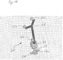
- FIG. 17 shows schematically the positioning of a cutting block 1 on a Thigh bone K according to the prior art.
- a guide rod 100 introduced into a bone K, wherein at the outer end of the guide rod 100 is a positioning mechanism 101 for positioning and holding the cutting block 1 is provided in a desired position. Is the cutting block 1 in the desired Position, so can be provided by provided in the cutting block 1 holes. 2
- Positioning pins 3, such as screws or nails or pins in the bone K be introduced for fixing the cutting block 1.
- the fixation of the Cutting block 1 on the bone K can be a preferably as perpendicular or easy to mechanical axis of the bone angled lying first cutting plane S0 means of a cutting tool 4, as shown schematically in Figs. 14A and 14B shown.
- the associated knee implant component to be able to position on the bone, further cuts in further to the cutting plane S0 obliquely extending or angled planes S1 to S4 generated be as shown in Figure 15.
- a second cutting block 10 on the first Cut level S0 placed and positioned by means of a suitable mechanism, with this second cutting block 10 more lateral cuts are made on the bone K, which by guiding the cutting tool 4 in the oblique or lateral Slots of the second cutting block 10 are generated.
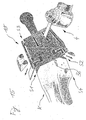
- the reference star 21 is fixedly connected to the main body 22, on which a rotatable element 23 is mounted, wherein at the outer end of the rotatable member 23 has two plates 24a and 24b of different thickness are arranged, which in a guide slot 1a of the tibial cutting block shown in Figs. 12A to 12E or one of the guide slots II, III of the femoral cutting block shown in Figure 13 are inserted can.
- the section shown in Figure 14 of the inserted with the Device 20 connected cutting block navigated to the desired location of the bone K be where the cutting block 1 with fasteners 3 attached to the bone K. can be as shown in Figure 14A. With a cutting tool 4 can then a section in the desired cutting plane, as shown in Figure 14B, are generated.
- a second cutting block 10 such as schematically shown in Figure 15, are plugged and through in the second cutting block 10 provided guide slots can perform cuts in the levels S1 to S4 so that, for example, an artificial joint can be put on which with correct position of the cutting plane S0 to S4 is also correctly positioned.
- the inventive device for determining the position of a cutting block has a positioning element, such as a reference star with at least a reference point or marker whose position in space can be detected.
- a positioning element such as a reference star with at least a reference point or marker whose position in space can be detected.
- at the positioning element can be active and / or passive elements, emit or reflect suitable signals from appropriate recording devices, such as cameras, to capture the spatial position of the positioning element and be able to determine the associated device.
- a position determining element is provided on the device according to the invention, which is firmly connected to the positioning element and which with an instrument or a device such as a cutting block or other Device having a surface to be navigated, can be connected.
- the position determination element consists of a reference element, such as For example, a reference plate whose surface is attached to an area at can serve an instrument to be navigated and serves as a reference plane, according to the invention at least one pressure element or clamping element is provided, which it allows the abutment surface of the reference element against an area of a navigating instrument can be pressed when the positioning element is inserted into an opening or a slot.
- a reference element such as a reference plate whose surface is attached to an area at can serve an instrument to be navigated and serves as a reference plane
- at least one pressure element or clamping element is provided, which it allows the abutment surface of the reference element against an area of a navigating instrument can be pressed when the positioning element is inserted into an opening or a slot.
- the at least one inventive Pressure plate may be formed so that one or more pressure elements or pressure plates with an example produced by a spring or a clamping element Force be pushed away from the reference element, whereby the reference element in connection with the at least one prestressed pressure element in one Opening or a slot can be tightly clamped or pinched, regardless of whether the opening or the slot have a precisely predetermined thickness or slightly different from this predetermined thickness, for example. That by a Force biased pressure element can thus prevent the invention Positioning element due to a game in a precisely defined positional relationship to the connected to the positioning element instrument.
- the position determining element or a part thereof i. H. the reference element and / or the pressure element about an axis relative to the positioning element or reference star rotatable, the axis preferably parallel to a normal is on the reference plane determined by the reference element. It is also advantageous when these elements are displaceable, wherein advantageously the reference element so is formed such that a contact surface on the reference element, which is a reference plane forms, can only be moved within the reference plane.
- a positioning element is preferably a reference star with three arranged thereon passive markers provided for navigation through the position determining element formed reference plane can be used.
- the reference and / or pressure element is at least one in a cutting block insertable plate, with several individual preferably lying in a plane Plate elements can be used as a reference and / or pressure element.
- the Pressure element is preferably in a direction perpendicular to that through the reference element movable formed investment or reference plane.
- a part of the pressure element be formed so that, for example, in a recess of the reference element can work and, for example, about the same thickness as the Thickness of a plate used as a reference element, so that the reference element together can be inserted with the pressure element in a slot.
- the pressure element by a spring or biasing element with a Stressed force, which out of the plane defined by the reference element out acts and preferably perpendicular to this plane, so that when inserting the reference element with the pressure element in a slot, the pressure element due to Biasing element is moved so far away from the reference element until the pressure element and the reference member fixed to side surfaces of a slot or an opening abut and thus a firm and defined connection between the positioning element and the instrument.
- the biasing element can, for example formed by one or more springs, for example, a coil spring between the reference element and the pressure element is provided so that the spring must be compressed to the reference element on the pressure element or in a To move recess of the pressure element into it, whereby the spring has a restoring force generated, with which the reference element again pushed away from the pressure element is to by the interaction of the reference element with the pressure element for Example, a non-positive or positive connection with a slot, which provided on an instrument to be able to produce.
- the spring element can be designed as a compression spring, as well as a tension spring or as a leaf spring and should be provided on the device according to the invention so that the reference element of the pressure element is moved away.
- the biasing element or a spring element on the inventive Device be provided so that by the force generated by the biasing element a Inhibited rotational movement of a freely rotatable positioning element or reference star can be and prefers the positioning element or the reference star in a fixed position can be detected or locked.
- the invention in another aspect, relates to a system for positioning a cutting block with a device as described above and a cutting block, which has at least one slot which uses as a guide slot can be and in which the position-determining element and in particular a Plate can be inserted, which firmly with the positioning element or reference star connected is.
- the device described can also be used to navigate other instruments which are an opening or a slot for insertion of the position-determining element exhibit.
- the present invention enables the defined and backlash-free attachment a positioning element or reference star at a slot or opening an instrument, wherein the slot or the opening have different thicknesses can, and can be ensured by the invention that one by a Reference element formed reference level can be navigated when the distance of the Positioning element to the reference element or serving as a reference plane Contact surface of the device is defined and, for example, a constant set Has distance, with the pressure element used for clamping a secure attachment at openings or slots of different thickness, so that the inventive Device implemented in software as a pre-calibrated device can be. It is also possible that a serving as a reference plane bearing surface for Verification or verification of the position of a surface, such as a Cut to a bone, can be used.
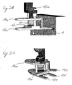
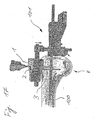
- Figures 1 and 2A to C show an inventive device 20 for determining the position of a cutting block 1 with a reference star 21, on which three as a reflective Ball surfaces formed markers 22a, 22b and 22c are attached.
- the reference star 21 is rotatable on the reference star holder 15 designed as an axle attached, which at its top and bottom plate-shaped closing elements 15a and 15b.
- the upper end element 15a shown in FIG. 1 prevents the connecting element 11 can be detached from the reference star holder 15.
- the reference star holder 15 protrudes through an opening of the pressing member 14 a and is on the Bottom connected to the lower end element 15b with the reference element 13a, whose underside serves as a reference plane.
- a spring 12a On top of the lower end 15b, a spring 12a is supported, which bears against the underside of the pressure element 14a pushes and thus pushes the pressure element 14a away from the reference element 13a.
- the Pressure element 14a is step-shaped and has a pressure plate 14e, which is pushed between two reference plates 13e and 13f of the reference element 13a can be as shown in Figure 2.
- a user may select the pressing member 14a and the reference member 13a between two fingers and by squeezing the elements 13a and 14a the spring 12a provided between these elements tension and the device in Insert a slot of a cutting block 1, so that after releasing the device 20 the pressure element 14a by the force of the spring 12a relative to the reference element 13a is moved up to the device fixed to the cutting block.
- 1 connect, wherein the positional relationship between the reference star 21 and by the Bottom of the reference element 13a formed reference plane remains constant, so that the Surface of the slot in the cutting block 1 abutting the reference plane by means of the Reference star 21 can be navigated. Due to the lower end element 14b acting spring force is the reference star 21 in the state shown in Figure 1 locked device according to the invention and can not be rotated.
- FIG 2C shows the device shown in Figures 1, 2A and 2B, wherein the pressure element 14a to allow easy cleaning of the device from the reference element 13a has been moved away.
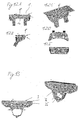
- FIGS. 3 to 5 show a second embodiment of the device according to the invention with a reference star 21, which has two rings 17a and 17b, the separated by a spacer 17c.
- the spacer 17c of the reference star 21 can between two clamping point forming latching elements 16a and 16b be connected to the reference element 13b.
- the reference element 13b is over two approximately vertically to the reference element 13b extending leaf springs 12b with a pressure element 14b, wherein, as shown in Figure 4, the pressing member 14b by a lateral displacement of the leaf springs 12b from the initial position shown in FIG can be moved so that the pressure plate 14e between the reference plates 13e and 13f of the reference element 13b is moved.
- the leaf springs 12b generate a restoring force the pressure element 14b relative to the reference element 13b, wherein also a Component of the restoring force perpendicular to the lower surface of the reference element 13b, which serves as a reference plane, whereby the shown in Figures 3 to 5 Device by the movement of the pressure plate 14e relative to the reference plates 13e and 13f can be attached without play to an opening or in a slot.
- FIGS. 6 to 8 A third embodiment of the device according to the invention is shown in FIGS. 6 to 8, wherein the pressure element 14c is approximately horizontal or parallel to the underside the reference element 13c extending leaf springs 12c with the reference element 13c is connected, again by the leaf springs 12c on the pressure plate 14e acting force can be generated, so that the pressure plate 14e from the out through the reference plates 13e and 13f of the reference element 13c can be moved to the reference star 21 fixed and in a defined positional relationship relative to the underside of the reference element 13a with an opening or a Gap to connect.
- the reference star 21 can be inserted by means of a ball pressure pin which can be pushed into the reference element 13c 16 are latched to the reference element 13c.
- FIGS. 9 to 11 show a fourth embodiment of the device according to the invention, wherein the reference star 21 with the reference element 13d in a similar manner as shown in the second embodiment can be locked.
- Unlike the Previous embodiments is not in the fourth embodiment by a separate spring biased pressure element provided because the play-free positioning the underside of the reference element 13d in an opening or a gap required Pressure force by the protruding from the reference element 13d elastic or spring elements 14d is generated, which due to their in the insertion direction existing bevel the insertion of the reference element 13d in a gap thereby allow the elastic or spring elements during insertion 12d are pressed into the plane of the reference element 13d and in the inserted Condition against one of the underside of the reference element 13d opposite Press the surface of an opening or a gap.
Landscapes
- Health & Medical Sciences (AREA)
- Surgery (AREA)
- Life Sciences & Earth Sciences (AREA)
- Heart & Thoracic Surgery (AREA)
- Molecular Biology (AREA)
- Oral & Maxillofacial Surgery (AREA)
- Engineering & Computer Science (AREA)
- Biomedical Technology (AREA)
- Veterinary Medicine (AREA)
- Medical Informatics (AREA)
- Nuclear Medicine, Radiotherapy & Molecular Imaging (AREA)
- Animal Behavior & Ethology (AREA)
- General Health & Medical Sciences (AREA)
- Public Health (AREA)
- Dentistry (AREA)
- Pathology (AREA)
- Surgical Instruments (AREA)
- Prostheses (AREA)
Abstract
Description
Die vorliegende Erfindung bezieht sich auf eine Vorrichtung zum Bestimmen der Position eines medizinischen Operationsinstrumentes, wie zum Beispiel eines Schneidblockes und kann auch zum Bestimmen der Position von Oberflächen, wie zum Beispiel einer Knochenoberfläche verwendet werden. Insbesondere bezieht sich die Erfindung auf eine Vorrichtung, welche beim Ermitteln einer räumlichen Position oder bei der Positionierung eines Elements verwendet werden kann.The present invention relates to a device for determining the position a medical surgical instrument, such as a cutting block and may also be used to determine the position of surfaces, such as a bone surface be used. In particular, the invention relates to a device, which when determining a spatial position or in the positioning of a Elements can be used.
Beim Anbringen von Implantaten, wie zum Beispiel künstlichen Knie-, Ellbogen, Fingeroder
Hüftgelenken, ist es erforderlich das Implantat, wie zum Beispiel ein Gelenk oder ein
Knochenteil, möglichst genau am angrenzenden Knochen zu positionieren. Hierzu müssen
möglichst exakte Schnitte an den an das Gelenk angrenzenden Knochenstrukturen ausgeführt
werden. Figur 17 zeigt schematisch die Positionierung eines Schneidblockes 1 an einem
Oberschenkelknochen K nach dem Stand der Technik. Hierzu wird eine Führungsstange
100 in einen Knochen K eingebracht, wobei am äußeren Ende der Führungsstange
100 eine Positionierungsmechanik 101 zum Positionieren und Halten des Schneidblockes 1
in einer gewünschten Position vorgesehen ist. Ist der Schneidblock 1 in die gewünschte
Position gebracht worden, so können durch in dem Schneidblock 1 vorgesehene Löcher 2
Positionierungsstifte 3, beispielsweise Schrauben oder Nägel bzw. Pins in den Knochen K
zur Fixierung des Schneidblocks 1 eingebracht werden. Nach erfolgter Fixierung des
Schneidblockes 1 am Knochen K kann eine bevorzugt möglichst senkrecht oder leicht zur
mechanischen Achse des Knochens abgewinkelt liegende erste Schnittebene S0 mittels
eines Schneidwerkzeuges 4 erzeugt werden, wie schematisch in den Figuren 14A und 14B
dargestellt. Um im Beispiel des Oberschenkelknochens die dazugehörige Knieimplantatkomponente
auf dem Knochen positionieren zu können, müssen weitere Schnitte in weiteren
zur Schnittebene S0 schräg verlaufenden oder abgewinkelten Ebenen S1 bis S4 erzeugt
werden, wie in Figur 15 gezeigt. Hierzu wird ein zweiter Schneidblock 10 auf die erste
Schnittebene S0 aufgesetzt und mittels einer geeigneten Mechanik positioniert, wobei mit
diesem zweiten Schneidblock 10 weitere seitliche Schnitte am Knochen K erzeugt werden,
welche durch Führung des Schneidwerkzeuges 4 in den schräg verlaufenden oder seitlichen
Schlitzen des zweiten Schneidblockes 10 erzeugt werden.When attaching implants, such as artificial knees, elbows, fingers or
Hip joints, it is required the implant, such as a joint or a
Bone part to position as closely as possible to the adjacent bone. To do this
perform as exact as possible cuts on the adjacent to the joint bone structures
become. FIG. 17 shows schematically the positioning of a
Aus der EP 1 190 676 A1 und der korrespondierenden US 6,551,325 der Anmelderin ist
eine Vorrichtung zum Bestimmen der Position eines Schneidblockes wie in Figur 16 gezeigt
bekannt, wobei die Vorrichtung einen Referenzstern 21 und darauf angeordnete kugelförmige
Elemente 22a bis 22c mit reflektierender Oberfläche aufweist, wobei zwei nicht
gezeigte Infrarotkameras ein an den kugelförmigen Elementen 22a bis 22c reflektiertes
Licht erfassen und hieraus die Lage des Referenzsternes 21 im Raum ermitteln. Der Referenzstern
21 ist fest mit dem Grundkörper 22 verbunden, an welchem ein drehbares Element
23 angebracht ist, wobei am äußeren Ende des drehbaren Elementes 23 zwei Platten
24a und 24b unterschiedlicher Dicke angeordnet sind, welche in einen Führungsschlitz 1a
des in den Figuren 12A bis 12E gezeigten tibialen Schneidblockes oder einen der Führungsschlitze
II, III des in Figur 13 gezeigten femoralen Schneidblockes eingesteckt werden
können. Zum Erzeugen des in Figur 14 gezeigten Schnittes muss der mit der eingesteckten
Vorrichtung 20 verbundene Schneidblock an die gewünschte Stelle des Knochens K navigiert
werden, wo der Schneidblock 1 mit Befestigungselementen 3 am Knochen K befestigt
werden kann, wie in Figur 14A gezeigt. Mit einem Schneidwerkzeug 4 kann anschließend
ein Schnitt in der gewünschten Schnittebene, wie in Figur 14B gezeigt, erzeugt werden.
Auf der so erzeugten Schnittebene des Knochens A kann ein zweiter Schneidblock 10, wie
schematisch in Figur 15 gezeigt, aufgesteckt werden und durch in dem zweiten Schneidblock
10 vorgesehene Führungsschlitze können Schnitte in den Ebenen S1 bis S4 ausgeführt
werden, so dass zum Beispiel ein künstliches Gelenk aufgesetzt werden kann, welches
bei richtiger Lage der Schnittebene S0 bis S4 auch richtig positioniert ist.From the
Es kann jedoch bei mehrfacher Verwendung der oben beschriebenen Positionierungsvorrichtung
20 zu Abnutzungen im Bereich der in Figur 16 gezeigten Platten 24a und 24b oder
zu einer Vergrößerung der Führungsschlitze 1a durch das Schneidwerkzeug 4 kommen,
was dazu führen kann, dass diese Platten 24 nicht mehr formgenau in einen Schlitz eines
Schneidblockes eingesteckt werden können, so dass der Schneidblock zum Beispiel aufgrund
eines vorhandenen Spiels und damit eines lockeren Sitzes ungenau positioniert wird.However, in multiple use of the above-described
Es ist die Aufgabe der vorliegenden Erfindung eine Vorrichtung zum Bestimmen der Position eines Schneidblockes oder eines medizinischen Operationsinstrumentes vorzuschlagen, welche eine sichere Positionsbestimmung auch nach mehrmaliger Verwendung sicherstellen können.It is the object of the present invention, a device for determining the position to propose a cutting block or a medical surgical instrument, which ensure a secure position determination even after repeated use can.
Diese Aufgabe wird durch die Merkmale des Anspruchs 1 gelöst. Vorteilhafte Ausführungsformen
ergeben sich aus den Unteransprüchen.This object is solved by the features of
Die erfindungsgemäße Vorrichtung zum Bestimmen der Position eines Schneidblockes weist ein Positionierungselement, wie zum Beispiel einen Referenzstern mit mindestens einem Referenzpunkt oder Marker auf, dessen Position im Raum erfasst werden kann. Bei dem Positionierungselement kann es sich um aktive und/oder passive Elemente handeln, die geeignete Signale abgeben bzw. reflektieren, welche von entsprechenden Aufnahmegeräten, wie zum Beispiel Kameras, erfasst werden, um so die räumliche Lage des Positionierungselements und der damit verbundenen Vorrichtung bestimmen zu können. Weiterhin ist an der erfindungsgemäßen Vorrichtung ein Positionsbestimmungselement vorgesehen, welches fest mit dem Positionierungselement verbunden ist und welches mit einem Instrument oder einer Vorrichtung, wie zum Beispiel einem Schneidblock oder einer anderen Vorrichtung, welche eine zu navigierende Fläche aufweist, verbunden werden kann. Erfindungsgemäß besteht das Positionsbestimmungselement aus einem Referenzelement, wie zum Beispiel einer Referenzplatte, deren eine Oberfläche als Anlage an eine Fläche bei einem zu navigierenden Instrument dienen kann und als Referenzebene dient, wobei erfindungsgemäß mindestens ein Andruckelement oder Spannelement vorgesehen ist, welches es ermöglicht, dass die Anlagefläche des Referenzelementes gegen eine Fläche eines zu navigierenden Instrumentes gedrückt werden kann, wenn das Positionsbestimmungselement in eine Öffnung oder einen Schlitz eingesteckt wird. Die mindestens eine erfindungsgemäße Andruckplatte kann so ausgebildet sein, dass ein oder mehrere Andruckelemente oder Andruckplatten mit einer zum Beispiel durch eine Feder oder ein Spannelement erzeugten Kraft von dem Referenzelement weggedrückt werden, wodurch das Referenzelement in Verbindung mit dem mindestens einen vorgespannten Andruckelement in einer Öffnung oder einem Schlitz festsitzend verspannt oder eingeklemmt werden kann, unabhängig davon, ob die Öffnung oder der Schlitz eine genau vorgegebene Dicke aufweisen oder zum Beispiel geringfügig von dieser vorgegebenen Dicke abweichen. Das durch eine Kraft vorgespannte Andruckelement kann somit erfindungsgemäß verhindern, dass das Positionierungselement aufgrund eines Spiels in keinem genau definierten Lageverhältnis zu dem mit dem Positionierungselement verbundenen Instrument steht.The inventive device for determining the position of a cutting block has a positioning element, such as a reference star with at least a reference point or marker whose position in space can be detected. at the positioning element can be active and / or passive elements, emit or reflect suitable signals from appropriate recording devices, such as cameras, to capture the spatial position of the positioning element and be able to determine the associated device. Farther a position determining element is provided on the device according to the invention, which is firmly connected to the positioning element and which with an instrument or a device such as a cutting block or other Device having a surface to be navigated, can be connected. According to the invention the position determination element consists of a reference element, such as For example, a reference plate whose surface is attached to an area at can serve an instrument to be navigated and serves as a reference plane, according to the invention at least one pressure element or clamping element is provided, which it allows the abutment surface of the reference element against an area of a navigating instrument can be pressed when the positioning element is inserted into an opening or a slot. The at least one inventive Pressure plate may be formed so that one or more pressure elements or pressure plates with an example produced by a spring or a clamping element Force be pushed away from the reference element, whereby the reference element in connection with the at least one prestressed pressure element in one Opening or a slot can be tightly clamped or pinched, regardless of whether the opening or the slot have a precisely predetermined thickness or slightly different from this predetermined thickness, for example. That by a Force biased pressure element can thus prevent the invention Positioning element due to a game in a precisely defined positional relationship to the connected to the positioning element instrument.
Vorzugsweise ist das Positionsbestimmungselement oder ein Teil davon, d. h. das Referenzelement und/oder das Andruckelement, um eine Achse relativ zum Positionierungselement oder Referenzstern drehbar, wobei die Achse vorzugsweise parallel zu einer Normalen auf der durch das Referenzelement bestimmten Referenzebene ist. Ebenso ist es vorteilhaft, wenn diese Elemente verschiebbar sind, wobei vorteilhaft das Referenzelement so ausgebildet ist, dass eine Anlagefläche an dem Referenzelement, welches eine Referenzebene bildet, nur innerhalb der Referenzebene verschoben werden kann.Preferably, the position determining element or a part thereof, i. H. the reference element and / or the pressure element about an axis relative to the positioning element or reference star rotatable, the axis preferably parallel to a normal is on the reference plane determined by the reference element. It is also advantageous when these elements are displaceable, wherein advantageously the reference element so is formed such that a contact surface on the reference element, which is a reference plane forms, can only be moved within the reference plane.
Als Positionierungselement ist bevorzugt ein Referenzstern mit drei darauf angeordneten passiven Markern vorgesehen, welche zur Navigation der durch das Positionsbestimmungselement gebildeten Referenzebene verwendet werden können.As a positioning element is preferably a reference star with three arranged thereon passive markers provided for navigation through the position determining element formed reference plane can be used.
Vorteilhaft ist das Referenz- und/oder Andruckelement mindestens eine in einen Schneidblock einsteckbare Platte, wobei auch mehrere einzelne bevorzugt in einer Ebene liegende Plattenelemente als Referenz- und/oder Andruckelement verwendet werden können. Das Andruckelement ist bevorzugt in einer Richtung senkrecht zu der durch das Referenzelement gebildeten Anlage- oder Referenzebene bewegbar. Vorteilhaft kann ein Teil des Andruckelements so ausgebildet sein, dass es zum Beispiel in eine Aussparung des Referenzelements gebracht werken kann und zum Beispiel etwa die gleiche Dicke aufweist wie die Dicke einer als Referenzelement verwendeten Platte, so dass das Referenzelement zusammen mit dem Andruckelement in einen Schlitz eingesteckt werden kann. Advantageously, the reference and / or pressure element is at least one in a cutting block insertable plate, with several individual preferably lying in a plane Plate elements can be used as a reference and / or pressure element. The Pressure element is preferably in a direction perpendicular to that through the reference element movable formed investment or reference plane. Advantageously, a part of the pressure element be formed so that, for example, in a recess of the reference element can work and, for example, about the same thickness as the Thickness of a plate used as a reference element, so that the reference element together can be inserted with the pressure element in a slot.
Vorzugsweise wird das Andruckelement durch ein Feder- oder Vorspannelement mit einer Kraft beaufschlagt, welche aus der durch das Referenzelement definierten Ebene heraus wirkt und bevorzugt senkrecht auf dieser Ebene steht, so dass beim Einstecken des Referenzelements mit dem Andruckelement in einen Schlitz das Andruckelement aufgrund des Vorspannelements so weit von dem Referenzelement wegbewegt wird, bis das Andruckelement und das Referenzelement fest an Seitenflächen eines Schlitzes oder einer Öffnung anliegen und somit eine feste und definierte Verbindung zwischen dem Positionierungselement und dem Instrument herstellen können. Das Vorspannelement kann zum Beispiel durch eine oder mehrere Federn gebildet werden, wobei beispielsweise eine Spiralfeder zwischen dem Referenzelement und dem Andruckelement so vorgesehen ist, dass die Feder komprimiert werden muss, um das Referenzelement auf das Andruckelement oder in eine Aussparung des Andruckelements hinein zu bewegen, wodurch die Feder eine Rückstellkraft erzeugt, mit welcher das Referenzelement wieder vom Andruckelement weggedrückt wird, um durch das Zusammenwirken des Referenzelements mit dem Andruckelement zum Beispiel eine kraftschlüssige oder auch formschlüssige Verbindung mit einem Schlitz, welcher an einem Instrument vorgesehen ist, herstellen zu können. Das Federelement kann sowohl als Druckfeder, als auch als Zugfeder oder als Blattfeder ausgebildet sein und sollte an der erfindungsgemäßen Vorrichtung so vorgesehen sein, dass das Referenzelement von dem Andruckelement weg bewegt wird.Preferably, the pressure element by a spring or biasing element with a Stressed force, which out of the plane defined by the reference element out acts and preferably perpendicular to this plane, so that when inserting the reference element with the pressure element in a slot, the pressure element due to Biasing element is moved so far away from the reference element until the pressure element and the reference member fixed to side surfaces of a slot or an opening abut and thus a firm and defined connection between the positioning element and the instrument. The biasing element can, for example formed by one or more springs, for example, a coil spring between the reference element and the pressure element is provided so that the spring must be compressed to the reference element on the pressure element or in a To move recess of the pressure element into it, whereby the spring has a restoring force generated, with which the reference element again pushed away from the pressure element is to by the interaction of the reference element with the pressure element for Example, a non-positive or positive connection with a slot, which provided on an instrument to be able to produce. The spring element can be designed as a compression spring, as well as a tension spring or as a leaf spring and should be provided on the device according to the invention so that the reference element of the pressure element is moved away.
Vorteilhaft kann das Vorspannelement oder ein Federelement an der erfindungsgemäßen Vorrichtung so vorgesehen sein, dass durch die vom Vorspannelement erzeugte Kraft eine Drehbewegung eines frei drehbaren Positionierungselementes oder Referenzsternes gehemmt werden kann und bevorzugt das Positionierungselement oder der Referenzstern in einer festen Position festgestellt oder arretiert werden kann.Advantageously, the biasing element or a spring element on the inventive Device be provided so that by the force generated by the biasing element a Inhibited rotational movement of a freely rotatable positioning element or reference star can be and prefers the positioning element or the reference star in a fixed position can be detected or locked.
Gemäß einem weiteren Aspekt bezieht sich die Erfindung auf ein System zum Positionieren eines Schneidblockes mit einer wie oben beschriebenen Vorrichtung und einem Schneidblock, welcher mindestens einen Schlitz aufweist, welcher als Führungsschlitz verwendet werden kann und in welchen das Positionsbestimmungselement und insbesondere eine Platte eingesteckt werden kann, welche fest mit dem Positionierungselement oder Referenzstern verbunden ist. In another aspect, the invention relates to a system for positioning a cutting block with a device as described above and a cutting block, which has at least one slot which uses as a guide slot can be and in which the position-determining element and in particular a Plate can be inserted, which firmly with the positioning element or reference star connected is.
Ebenso kann die beschriebene Vorrichtung auch zum Navigieren anderer Instrumente verwendet werden, welche eine Öffnung oder einen Schlitz zum Einstecken des Positionsbestimmungselementes aufweisen.Likewise, the device described can also be used to navigate other instruments which are an opening or a slot for insertion of the position-determining element exhibit.
Demzufolge ermöglicht die vorliegende Erfindung das definierte und spielfreie Anbringen eines Positionierungselementes oder Referenzsternes an einem Schlitz oder einer Öffnung eines Instruments, wobei der Schlitz oder die Öffnung unterschiedliche Dicken aufweisen können, und wobei durch die Erfindung sichergestellt werden kann, dass eine durch ein Referenzelement gebildete Referenzebene navigiert werden kann, wenn der Abstand des Positionierungselements zum Referenzelement oder zu einer als Referenzebene dienenden Anlagefläche der Vorrichtung definiert ist und zum Beispiel einen konstanten festgelegten Abstand hat, wobei das zum Festklemmen verwendete Andruckelement eine sichere Befestigung an Öffnungen oder Schlitzen mit verschiedener Dicke ermöglicht, so dass die erfindungsgemäße Vorrichtung in einer Software als vorkalibrierte Vorrichtung implementiert werden kann. Es ist auch möglich, dass eine als Referenzebene dienende Anlagefläche zur Verifikation oder Überprüfung der Position einer Oberfläche, wie zum Beispiel eines Schnittes an einem Knochen, verwendet werden kann.Consequently, the present invention enables the defined and backlash-free attachment a positioning element or reference star at a slot or opening an instrument, wherein the slot or the opening have different thicknesses can, and can be ensured by the invention that one by a Reference element formed reference level can be navigated when the distance of the Positioning element to the reference element or serving as a reference plane Contact surface of the device is defined and, for example, a constant set Has distance, with the pressure element used for clamping a secure attachment at openings or slots of different thickness, so that the inventive Device implemented in software as a pre-calibrated device can be. It is also possible that a serving as a reference plane bearing surface for Verification or verification of the position of a surface, such as a Cut to a bone, can be used.
Die Erfindung wird nachfolgend anhand von Ausführungsbeispielen beschrieben werden.The invention will be described below with reference to exemplary embodiments.
Es zeigen:
Figuren 1 und 2A-C- eine erste Ausführungsform einer erfindungsgemäßen Vorrichtung;
Figuren 3 bis 5- eine zweite Ausführungsform der erfindungsgemäßen Vorrichtung;
- Figuren 6 bis 8
- eine dritte Ausführungsform der erfindungsgemäßen Vorrichtung;
- Figuren 9 bis 11
- eine vierte Ausführungsform der erfindungemäßen Vorrichtung;
- Figuren 12A bis 12B
- verschiedene Ansichten eines tibialen Schneidblocks;
- Figur 13
- zwei Ansichten eines femoralen Schneidblocks;
- Figuren 14A und 14B
- das Schneiden eines Knochens mit einem positionierten Schneidblock;
Figur 15- das Schneiden der Schnittebenen S1 bis S6 mit einem zweiten Schneidblock;
Figur 16- eine bekannte Vorrichtung zur Positionierung eines Schneidblocks; und
Figur 17- die Positionierung eines Schneidblockes nach dem Stand der Technik;
- Figures 1 and 2A-C
- a first embodiment of a device according to the invention;
- FIGS. 3 to 5
- a second embodiment of the device according to the invention;
- FIGS. 6 to 8
- a third embodiment of the device according to the invention;
- FIGS. 9 to 11
- A fourth embodiment of erfindungemäßen device;
- FIGS. 12A to 12B
- different views of a tibial cutting block;
- FIG. 13
- two views of a femoral cutting block;
- Figures 14A and 14B
- cutting a bone with a positioned cutting block;
- FIG. 15
- cutting the cutting planes S1 to S6 with a second cutting block;
- FIG. 16
- a known device for positioning a cutting block; and
- FIG. 17
- the positioning of a cutting block according to the prior art;
Die Figuren 1 und 2A bis C zeigen eine erfindungsgemäße Vorrichtung 20 zum Bestimmen
der Position eines Schneidblockes 1 mit einem Referenzstern 21, an welchem drei als reflektierende
Kugeloberflächen ausgebildete Marker 22a, 22b und 22c befestigt sind. Der
Referenzstern 21 ist über ein eine Drehbewegung ermöglichendes Verbindungselement 11,
welches als Klammer oder Buchse ausgebildet sein kann. Mittels des Verbindungselements
11 ist der Referenzstern 21 drehbar an dem als Achse ausgebildeten Referenzsternhalter 15
befestigt, welcher an seiner Ober- und Unterseite jeweils tellerförmige Abschlusselemente
15a und 15b aufweist. Das in Figur 1 gezeigte obere Abschlusselement 15a verhindert, dass
sich das Verbindungselement 11 vom Referenzsternhalter 15 lösen kann. Der Referenzsternhalter
15 ragt durch eine Öffnung des Andruckelements 14a hindurch und ist auf der
Unterseite mit dem unteren Abschlusselement 15b mit dem Referenzelement 13a verbunden,
dessen Unterseite als Referenzebene dient. Auf der Oberseite des unteren Abschlusses
15b stützt sich eine Feder 12a ab, welche gegen die Unterseite des Andruckelements 14a
drückt und somit das Andruckelement 14a von dem Referenzelement 13a weg drückt. Das
Andruckelement 14a ist stufenförmig ausgebildet und weist eine Andruckplatte 14e auf,
welche zwischen zwei Referenzplatten 13e und 13f des Referenzelementes 13a geschoben
werden kann wie in Figur 2 gezeigt. Figures 1 and 2A to C show an
Ein Benutzer kann zum Beispiel das Andruckelement 14a und das Referenzelement 13a
zwischen zwei Finger nehmen und durch ein Zusammendrücken der Elemente 13a und 14a
die zwischen diesen Elementen vorgesehener Feder 12a spannen und die Vorrichtung in
einen Schlitz eines Schneidblockes 1 einschieben, so dass nach dem Loslassen der Vorrichtung
20 das Andruckelement 14a durch die Kraft der Feder 12a relativ zum Referenzelement
13a nach oben verschoben wird, um die Vorrichtung fest mit dem Schneidblock 1
zu verbinden, wobei das Lageverhältnis zwischen dem Referenzstern 21 und der durch die
Unterseite des Referenzelementes 13a gebildete Referenzebene konstant bleibt, so dass die
an die Referenzebene anliegende Oberfläche des Schlitzes im Schneidblock 1 mittels des
Referenzsternes 21 navigiert werden kann. Aufgrund der auf das untere Abschlusselement
14b wirkende Federkraft wird der Referenzstern 21 in dem in Figur 1 gezeigten Zustand der
erfindungsgemäßen Vorrichtung arretiert und kann nicht mehr gedreht werden.For example, a user may select the
Figur 2C zeigt die in den Figuren 1, 2A und 2B gezeigte Vorrichtung, wobei das Andruckelement
14a zur Ermöglichung einer einfachen Reinigung der Vorrichtung von dem Referenzelement
13a weg bewegt worden ist.Figure 2C shows the device shown in Figures 1, 2A and 2B, wherein the
Die Figuren 3 bis 5 zeigen eine zweite Ausführungsform der erfindungsgemäßen Vorrichtung
mit einem Referenzstern 21, welcher zwei Ringe 17a und 17b aufweist, die
durch ein Abstandsstück 17c voneinander getrennt sind. Das Abstandsstück 17c des Referenzsternes
21 kann zwischen zwei eine Klemmstelle bildende Rastelementen 16a und 16b
mit dem Referenzelement 13b verbunden werden. Das Referenzelement 13b ist über zwei
etwa vertikal zum Referenzelement 13b verlaufende Blattfedern 12b mit einem Andruckelement
14b verbunden, wobei wie in Figur 4 gezeigt das Andruckelement 14b durch eine
seitliche Verschiebung der Blattfedern 12b aus der in Figur 3 gezeigten Ausgangsstellung
so bewegt werden kann, dass die Andruckplatte 14e zwischen die Referenzplatten 13e und
13f des Referenzelementes 13b bewegt wird. Wenn die in Figur 4 gezeigten Referenzplatten
13e und 13f zusammen mit der Andruckplatte 14e in einen Schlitz oder eine Öffnung
eines Instrumentes eingefügt werden, so erzeugen die Blattfedern 12b ein Rückstellkraft
des Andruckelements 14b relativ zu dem Referenzelement 13b, wobei auch eine
Komponente der Rückstellkraft senkrecht zur unteren Oberfläche des Referenzelementes
13b wirkt, welche als Referenzebene dient, wodurch die in den Figuren 3 bis 5 gezeigte
Vorrichtung durch die Bewegung der Andruckplatte 14e relativ zu den Referenzplatten
13e und 13f spielfrei an einer Öffnung oder in einem Schlitz befestigt werden kann.FIGS. 3 to 5 show a second embodiment of the device according to the invention
with a
Eine dritte Ausführungsform der erfindungsgemäßen Vorrichtung ist in den Figuren 6 bis
8 gezeigt, wobei das Andruckelement 14c über etwa horizontal bzw. parallel zur Unterseite
des Referenzelementes 13c verlaufende Blattfedern 12c mit dem Referenzelement
13c verbunden ist, wobei wiederum durch die Blattfedern 12c eine auf die Andruckplatte
14e wirkende Kraft erzeugt werden kann, so dass sich die Andruckplatte 14e aus der
durch die Referenzplatten 13e und 13f des Referenzelementes 13c gebildeten Ebene heraus
bewegt werden kann, um den Referenzstern 21 fest und in einem definierten Lageverhältnis
relativ zur Unterseite des Referenzelementes 13a mit einer Öffnung oder einem
Spalt zu verbinden.A third embodiment of the device according to the invention is shown in FIGS. 6 to
8, wherein the pressure element 14c is approximately horizontal or parallel to the underside
the
Der Referenzstern 21 kann mittels eines in das Referenzelement 13c einschiebbaren Kugeldruckstiftes
16 mit dem Referenzelement 13c verrastet werden.The
Die Figuren 9 bis 11 zeigen eine vierte Ausführungsform der erfindungsgemäßen Vorrichtung,
wobei der Referenzstern 21 mit dem Referenzelement 13d auf ähnliche Weise
wie im zweiten Ausführungsbeispiel gezeigt verrastet werden kann. Anders als bei den
vorhergehenden Ausführungsbeispielen ist im vierten Ausführungsbeispiel kein durch eine
separate Feder vorgespanntes Andruckelement vorgesehen, da die zur spielfreien Positionierung
der Unterseite des Referenzelementes 13d in einer Öffnung oder einem Spalt erforderliche
Andruckkraft durch die aus dem Referenzelement 13d herausragenden elastischen
oder Federelemente 14d erzeugt wird, welche aufgrund ihrer in Einschubrichtung
vorhandenen Abschrägung das Einschieben des Referenzelementes 13d in einen Spalt
dadurch ermöglichen, dass während des Einschiebens die elastischen oder Federelemente
12d in die Ebene des Referenzelementes 13d hineingedrückt werden und im eingeschobenen
Zustand gegen eine der Unterseite des Referenzelementes 13d gegenüberliegende
Fläche einer Öffnung oder eines Spaltes drücken.FIGS. 9 to 11 show a fourth embodiment of the device according to the invention,
wherein the
Claims (7)
Priority Applications (3)
| Application Number | Priority Date | Filing Date | Title |
|---|---|---|---|
| DE502004009884T DE502004009884D1 (en) | 2004-02-03 | 2004-02-03 | Device for determining the position of a cutting block |
| EP04002321A EP1561431B1 (en) | 2004-02-03 | 2004-02-03 | Device for determining the position of a cutting guide |
| US11/050,421 US7497029B2 (en) | 2004-02-03 | 2005-02-03 | Device for determining the position of an incision block |
Applications Claiming Priority (1)
| Application Number | Priority Date | Filing Date | Title |
|---|---|---|---|
| EP04002321A EP1561431B1 (en) | 2004-02-03 | 2004-02-03 | Device for determining the position of a cutting guide |
Publications (2)
| Publication Number | Publication Date |
|---|---|
| EP1561431A1 true EP1561431A1 (en) | 2005-08-10 |
| EP1561431B1 EP1561431B1 (en) | 2009-08-12 |
Family
ID=35796953
Family Applications (1)
| Application Number | Title | Priority Date | Filing Date |
|---|---|---|---|
| EP04002321A Expired - Lifetime EP1561431B1 (en) | 2004-02-03 | 2004-02-03 | Device for determining the position of a cutting guide |
Country Status (3)
| Country | Link |
|---|---|
| US (1) | US7497029B2 (en) |
| EP (1) | EP1561431B1 (en) |
| DE (1) | DE502004009884D1 (en) |
Cited By (3)
| Publication number | Priority date | Publication date | Assignee | Title |
|---|---|---|---|---|
| DE102006035602A1 (en) * | 2006-07-31 | 2008-02-07 | Plus Orthopedics Ag | Clamp for attaching surgical operating aids, actuator for such a clamp and an assembly comprising an actuator and a clamp |
| EP1976446A1 (en) * | 2006-01-25 | 2008-10-08 | Orthosoft, Inc. | Cas system for condyle measurement |
| EP2160986A1 (en) | 2008-09-05 | 2010-03-10 | BrainLAB AG | Device for attaching a marker device to a bone |
Families Citing this family (46)
| Publication number | Priority date | Publication date | Assignee | Title |
|---|---|---|---|---|
| US6928742B2 (en) * | 2000-08-31 | 2005-08-16 | Plus Orthopedics Ag | Method and apparatus for finding the position of a mechanical axis of a limb |
| US7998062B2 (en) | 2004-03-29 | 2011-08-16 | Superdimension, Ltd. | Endoscope structures and techniques for navigating to a target in branched structure |
| DE10306793A1 (en) * | 2002-05-21 | 2003-12-04 | Plus Endoprothetik Ag Rotkreuz | Arrangement and method for the intraoperative determination of the position of a joint replacement implant |
| WO2004112610A2 (en) * | 2003-06-09 | 2004-12-29 | Vitruvian Orthopaedics, Llc | Surgical orientation device and method |
| US7559931B2 (en) | 2003-06-09 | 2009-07-14 | OrthAlign, Inc. | Surgical orientation system and method |
| EP2316328B1 (en) | 2003-09-15 | 2012-05-09 | Super Dimension Ltd. | Wrap-around holding device for use with bronchoscopes |
| DE602004022432D1 (en) | 2003-09-15 | 2009-09-17 | Super Dimension Ltd | SYSTEM FROM ACCESSORIES FOR USE WITH BRONCHOSCOPES |
| US8764725B2 (en) | 2004-02-09 | 2014-07-01 | Covidien Lp | Directional anchoring mechanism, method and applications thereof |
| US7182767B2 (en) * | 2004-05-19 | 2007-02-27 | Howmedica Osteonics Corp. | Navigated lateral/medial femoral resection guide |
| US8192449B2 (en) * | 2005-10-25 | 2012-06-05 | Brainlab Ag | Non-penetrating fixing device |
| US20080161824A1 (en) * | 2006-12-27 | 2008-07-03 | Howmedica Osteonics Corp. | System and method for performing femoral sizing through navigation |
| DE102007011568A1 (en) * | 2007-03-08 | 2008-09-11 | Cas Innovations Ag | Medical clamp, in particular spinal clamp |
| US8905920B2 (en) | 2007-09-27 | 2014-12-09 | Covidien Lp | Bronchoscope adapter and method |
| WO2009122273A2 (en) | 2008-04-03 | 2009-10-08 | Superdimension, Ltd. | Magnetic interference detection system and method |
| EP2297673B1 (en) | 2008-06-03 | 2020-04-22 | Covidien LP | Feature-based registration method |
| US8218847B2 (en) | 2008-06-06 | 2012-07-10 | Superdimension, Ltd. | Hybrid registration method |
| US8932207B2 (en) | 2008-07-10 | 2015-01-13 | Covidien Lp | Integrated multi-functional endoscopic tool |
| CA3050929A1 (en) | 2008-07-24 | 2010-01-28 | OrthAlign, Inc. | Systems and methods for joint replacement |
| AU2009291743B2 (en) | 2008-09-10 | 2015-02-05 | Orthalign, Inc | Hip surgery systems and methods |
| US8611984B2 (en) | 2009-04-08 | 2013-12-17 | Covidien Lp | Locatable catheter |
| EP2248484B1 (en) * | 2009-05-06 | 2011-07-06 | BrainLAB AG | Tool for recording levels of a bone and allocated data processing method |
| US10869771B2 (en) | 2009-07-24 | 2020-12-22 | OrthAlign, Inc. | Systems and methods for joint replacement |
| US8118815B2 (en) | 2009-07-24 | 2012-02-21 | OrthAlign, Inc. | Systems and methods for joint replacement |
| CA2825042C (en) * | 2010-01-21 | 2021-01-05 | OrthAlign, Inc. | Systems and methods for joint replacement |
| WO2011107147A1 (en) * | 2010-03-03 | 2011-09-09 | Brainlab Ag | Method for enabling medical navigation with minimised invasiveness |
| US10582834B2 (en) | 2010-06-15 | 2020-03-10 | Covidien Lp | Locatable expandable working channel and method |
| WO2013173700A1 (en) | 2012-05-18 | 2013-11-21 | OrthAlign, Inc. | Devices and methods for knee arthroplasty |
| US9649160B2 (en) | 2012-08-14 | 2017-05-16 | OrthAlign, Inc. | Hip replacement navigation system and method |
| US9151587B2 (en) * | 2013-11-11 | 2015-10-06 | General Electric Company | Bucket tip shroud measurement fixture and method of measuring bucket tip shroud orientation |
| US10952593B2 (en) | 2014-06-10 | 2021-03-23 | Covidien Lp | Bronchoscope adapter |
| US9539679B2 (en) * | 2014-07-31 | 2017-01-10 | The Boeing Company | Alignment tool |
| US10363149B2 (en) | 2015-02-20 | 2019-07-30 | OrthAlign, Inc. | Hip replacement navigation system and method |
| US10426555B2 (en) | 2015-06-03 | 2019-10-01 | Covidien Lp | Medical instrument with sensor for use in a system and method for electromagnetic navigation |
| US10478254B2 (en) | 2016-05-16 | 2019-11-19 | Covidien Lp | System and method to access lung tissue |
| US10517505B2 (en) | 2016-10-28 | 2019-12-31 | Covidien Lp | Systems, methods, and computer-readable media for optimizing an electromagnetic navigation system |
| US10615500B2 (en) | 2016-10-28 | 2020-04-07 | Covidien Lp | System and method for designing electromagnetic navigation antenna assemblies |
| US10751126B2 (en) | 2016-10-28 | 2020-08-25 | Covidien Lp | System and method for generating a map for electromagnetic navigation |
| US10792106B2 (en) | 2016-10-28 | 2020-10-06 | Covidien Lp | System for calibrating an electromagnetic navigation system |
| US10446931B2 (en) | 2016-10-28 | 2019-10-15 | Covidien Lp | Electromagnetic navigation antenna assembly and electromagnetic navigation system including the same |
| US10722311B2 (en) | 2016-10-28 | 2020-07-28 | Covidien Lp | System and method for identifying a location and/or an orientation of an electromagnetic sensor based on a map |
| US10638952B2 (en) | 2016-10-28 | 2020-05-05 | Covidien Lp | Methods, systems, and computer-readable media for calibrating an electromagnetic navigation system |
| US10418705B2 (en) | 2016-10-28 | 2019-09-17 | Covidien Lp | Electromagnetic navigation antenna assembly and electromagnetic navigation system including the same |
| CA3056495A1 (en) | 2017-03-14 | 2018-09-20 | OrthAlign, Inc. | Soft tissue measurement & balancing systems and methods |
| US10918499B2 (en) | 2017-03-14 | 2021-02-16 | OrthAlign, Inc. | Hip replacement navigation systems and methods |
| US11219489B2 (en) | 2017-10-31 | 2022-01-11 | Covidien Lp | Devices and systems for providing sensors in parallel with medical tools |
| CN112423682A (en) * | 2018-05-18 | 2021-02-26 | 史密夫和内修有限公司 | System and method for tracking an ablation plane |
Citations (5)
| Publication number | Priority date | Publication date | Assignee | Title |
|---|---|---|---|---|
| WO2000041635A1 (en) * | 1999-01-18 | 2000-07-20 | Aesculap | Implant with support marker and instrument for setting same |
| EP1249207A2 (en) * | 1993-02-12 | 2002-10-16 | George S. Allen | Fiducial marker |
| FR2830743A1 (en) * | 2001-10-11 | 2003-04-18 | Surgiview Sa | Feeler and transmitter pen for surgery, comprises cylindrical pen case with internal guide bearings for spring loaded rod, the rod having a contact sphere at one end and marker transmitters at other |
| US6551325B2 (en) * | 2000-09-26 | 2003-04-22 | Brainlab Ag | Device, system and method for determining the position of an incision block |
| WO2004017842A2 (en) * | 2002-08-23 | 2004-03-04 | Orthosoft Inc. | Surgical universal positioning block and tool guide |
Family Cites Families (17)
| Publication number | Priority date | Publication date | Assignee | Title |
|---|---|---|---|---|
| US5213112A (en) * | 1992-01-29 | 1993-05-25 | Pfizer Hospital Products Group, Inc. | Tension meter for orthopedic surgery |
| US5445642A (en) * | 1992-09-01 | 1995-08-29 | Depuy Inc. | Method for installing a femoral component |
| US5417694A (en) * | 1993-11-08 | 1995-05-23 | Smith & Nephew Richards Inc. | Distal femoral cutting guide apparatus with anterior or posterior referencing for use in knee joint replacement surgery |
| US5601566A (en) * | 1994-02-22 | 1997-02-11 | Osteonics Corp. | Method and apparatus for the alignment of a femoral knee prosthesis |
| US6695848B2 (en) * | 1994-09-02 | 2004-02-24 | Hudson Surgical Design, Inc. | Methods for femoral and tibial resection |
| US5910143A (en) * | 1994-12-16 | 1999-06-08 | Exactech, Inc. | Intramedullary alignment guide tool |
| US6073360A (en) * | 1997-01-22 | 2000-06-13 | Js Research And Development, Inc. | Instrument mount with spring-loaded clamp |
| US6059531A (en) * | 1998-06-19 | 2000-05-09 | Tai; Jen-Lung David | Impeller and fan blade attachment assembly |
| US6514259B2 (en) * | 2001-02-02 | 2003-02-04 | Carnegie Mellon University | Probe and associated system and method for facilitating planar osteotomy during arthoplasty |
| US7993353B2 (en) * | 2002-06-04 | 2011-08-09 | Brainlab Ag | Medical tracking system with universal interface |
| US7029477B2 (en) * | 2002-12-20 | 2006-04-18 | Zimmer Technology, Inc. | Surgical instrument and positioning method |
| DE20303499U1 (en) * | 2003-02-26 | 2003-04-30 | Aesculap AG & Co. KG, 78532 Tuttlingen | Patella reference device |
| FR2852223B1 (en) * | 2003-03-11 | 2005-06-10 | Perception Raisonnement Action En Medecine | INSTRUMENT FOR TRACKING THE POSITION OF A CUTTING PLAN |
| US7111863B2 (en) * | 2003-07-15 | 2006-09-26 | Ward Robert J | Trailer alignment aid with universal mounting device |
| US20050215888A1 (en) * | 2004-03-05 | 2005-09-29 | Grimm James E | Universal support arm and tracking array |
| TWI272163B (en) * | 2005-07-26 | 2007-02-01 | Benq Corp | Prying tools |
| US7337515B2 (en) * | 2006-01-25 | 2008-03-04 | Breaching Technologies, Inc. | Hybrid breaching bar |
-
2004
- 2004-02-03 DE DE502004009884T patent/DE502004009884D1/en not_active Expired - Lifetime
- 2004-02-03 EP EP04002321A patent/EP1561431B1/en not_active Expired - Lifetime
-
2005
- 2005-02-03 US US11/050,421 patent/US7497029B2/en active Active
Patent Citations (5)
| Publication number | Priority date | Publication date | Assignee | Title |
|---|---|---|---|---|
| EP1249207A2 (en) * | 1993-02-12 | 2002-10-16 | George S. Allen | Fiducial marker |
| WO2000041635A1 (en) * | 1999-01-18 | 2000-07-20 | Aesculap | Implant with support marker and instrument for setting same |
| US6551325B2 (en) * | 2000-09-26 | 2003-04-22 | Brainlab Ag | Device, system and method for determining the position of an incision block |
| FR2830743A1 (en) * | 2001-10-11 | 2003-04-18 | Surgiview Sa | Feeler and transmitter pen for surgery, comprises cylindrical pen case with internal guide bearings for spring loaded rod, the rod having a contact sphere at one end and marker transmitters at other |
| WO2004017842A2 (en) * | 2002-08-23 | 2004-03-04 | Orthosoft Inc. | Surgical universal positioning block and tool guide |
Cited By (5)
| Publication number | Priority date | Publication date | Assignee | Title |
|---|---|---|---|---|
| EP1976446A1 (en) * | 2006-01-25 | 2008-10-08 | Orthosoft, Inc. | Cas system for condyle measurement |
| EP1976446A4 (en) * | 2006-01-25 | 2015-04-15 | Orthosoft Inc | Cas system for condyle measurement |
| DE102006035602A1 (en) * | 2006-07-31 | 2008-02-07 | Plus Orthopedics Ag | Clamp for attaching surgical operating aids, actuator for such a clamp and an assembly comprising an actuator and a clamp |
| EP2160986A1 (en) | 2008-09-05 | 2010-03-10 | BrainLAB AG | Device for attaching a marker device to a bone |
| US9095376B2 (en) | 2008-09-05 | 2015-08-04 | Brainlab Ag | Device for fastening a marker device to a bone |
Also Published As
| Publication number | Publication date |
|---|---|
| US7497029B2 (en) | 2009-03-03 |
| EP1561431B1 (en) | 2009-08-12 |
| US20050190380A1 (en) | 2005-09-01 |
| DE502004009884D1 (en) | 2009-09-24 |
Similar Documents
| Publication | Publication Date | Title |
|---|---|---|
| EP1561431B1 (en) | Device for determining the position of a cutting guide | |
| EP1470786B1 (en) | Device for preparation of a femoral condyle | |
| EP1413258B1 (en) | Device and method for calibrating an element | |
| EP1190676B1 (en) | Device for determining the position of a cutting guide | |
| DE60214290T2 (en) | Auxiliary device for positioning a humeral part of an elbow prosthesis | |
| EP1596749B1 (en) | Patella-referencing device | |
| EP0919195B1 (en) | Tool assembly for a prosthetic knee | |
| DE60216667T2 (en) | Device for positioning the cutting plane of a bone saw guide | |
| EP1470787B1 (en) | Device for preparation of a femoral condyle | |
| EP1442714A1 (en) | Aiming aid for vertebrae | |
| EP2123229A1 (en) | Connecting cutting blocks | |
| EP1771116A1 (en) | Instruments and method for machining a cervical vertebral body | |
| EP1470788A1 (en) | Bone cutting guide | |
| DE3842645A1 (en) | SAFE GAUGE SYSTEM | |
| EP1543784B1 (en) | Resection cutting jig and method for positioning the resection cutting jig | |
| EP3075330B1 (en) | Medical guiding device | |
| DE29614349U1 (en) | Arrangement for inserting a femoral knee-sliding surface endoprosthesis | |
| EP1413257B1 (en) | Device for positioning an element, for example in the spine | |
| EP1667596A1 (en) | Bone fixed locator and optical navigation system | |
| EP3429484A1 (en) | Surgical device for surgery of the human knee | |
| EP2081505B1 (en) | Jig for performing a transposition osteotomy | |
| EP3095398A1 (en) | Patient-specific instrument for the referencing of body parts | |
| DE19716300C1 (en) | Knee joint prosthesis support | |
| EP1504734B1 (en) | Insertion instrument for sliding prostheses | |
| DE102023104682A1 (en) | A DEVICE AND METHOD FOR ALIGNING SURGICAL TOOLS |
Legal Events
| Date | Code | Title | Description |
|---|---|---|---|
| PUAI | Public reference made under article 153(3) epc to a published international application that has entered the european phase |
Free format text: ORIGINAL CODE: 0009012 |
|
| 17P | Request for examination filed |
Effective date: 20040203 |
|
| AK | Designated contracting states |
Kind code of ref document: A1 Designated state(s): AT BE BG CH CY CZ DE DK EE ES FI FR GB GR HU IE IT LI LU MC NL PT RO SE SI SK TR |
|
| AX | Request for extension of the european patent |
Extension state: AL LT LV MK |
|
| AKX | Designation fees paid |
Designated state(s): DE FR GB IT |
|
| 17Q | First examination report despatched |
Effective date: 20060524 |
|
| RAP1 | Party data changed (applicant data changed or rights of an application transferred) |
Owner name: BRAINLAB AG |
|
| GRAP | Despatch of communication of intention to grant a patent |
Free format text: ORIGINAL CODE: EPIDOSNIGR1 |
|
| GRAS | Grant fee paid |
Free format text: ORIGINAL CODE: EPIDOSNIGR3 |
|
| GRAA | (expected) grant |
Free format text: ORIGINAL CODE: 0009210 |
|
| AK | Designated contracting states |
Kind code of ref document: B1 Designated state(s): DE FR GB IT |
|
| REG | Reference to a national code |
Ref country code: GB Ref legal event code: FG4D Free format text: NOT ENGLISH |
|
| REF | Corresponds to: |
Ref document number: 502004009884 Country of ref document: DE Date of ref document: 20090924 Kind code of ref document: P |
|
| PLBE | No opposition filed within time limit |
Free format text: ORIGINAL CODE: 0009261 |
|
| STAA | Information on the status of an ep patent application or granted ep patent |
Free format text: STATUS: NO OPPOSITION FILED WITHIN TIME LIMIT |
|
| 26N | No opposition filed |
Effective date: 20100517 |
|
| PG25 | Lapsed in a contracting state [announced via postgrant information from national office to epo] |
Ref country code: IT Free format text: LAPSE BECAUSE OF FAILURE TO SUBMIT A TRANSLATION OF THE DESCRIPTION OR TO PAY THE FEE WITHIN THE PRESCRIBED TIME-LIMIT Effective date: 20090812 |
|
| REG | Reference to a national code |
Ref country code: DE Ref legal event code: R082 Ref document number: 502004009884 Country of ref document: DE Representative=s name: SCHWABE SANDMAIR MARX, DE |
|
| REG | Reference to a national code |
Ref country code: DE Ref legal event code: R081 Ref document number: 502004009884 Country of ref document: DE Owner name: BRAINLAB AG, DE Free format text: FORMER OWNER: BRAINLAB AG, 85622 FELDKIRCHEN, DE Effective date: 20131104 Ref country code: DE Ref legal event code: R082 Ref document number: 502004009884 Country of ref document: DE Representative=s name: SCHWABE SANDMAIR MARX, DE Effective date: 20131104 Ref country code: DE Ref legal event code: R082 Ref document number: 502004009884 Country of ref document: DE Representative=s name: SCHWABE SANDMAIR MARX PATENTANWAELTE RECHTSANW, DE Effective date: 20131104 |
|
| REG | Reference to a national code |
Ref country code: FR Ref legal event code: PLFP Year of fee payment: 13 |
|
| REG | Reference to a national code |
Ref country code: FR Ref legal event code: PLFP Year of fee payment: 14 |
|
| REG | Reference to a national code |
Ref country code: DE Ref legal event code: R082 Ref document number: 502004009884 Country of ref document: DE Representative=s name: SSM SANDMAIR PATENTANWAELTE RECHTSANWALT PARTN, DE Ref country code: DE Ref legal event code: R082 Ref document number: 502004009884 Country of ref document: DE Representative=s name: SCHWABE SANDMAIR MARX PATENTANWAELTE RECHTSANW, DE Ref country code: DE Ref legal event code: R081 Ref document number: 502004009884 Country of ref document: DE Owner name: BRAINLAB AG, DE Free format text: FORMER OWNER: BRAINLAB AG, 85622 FELDKIRCHEN, DE |
|
| REG | Reference to a national code |
Ref country code: FR Ref legal event code: CA Effective date: 20170706 |
|
| REG | Reference to a national code |
Ref country code: FR Ref legal event code: PLFP Year of fee payment: 15 |
|
| PGFP | Annual fee paid to national office [announced via postgrant information from national office to epo] |
Ref country code: FR Payment date: 20230220 Year of fee payment: 20 |
|
| PGFP | Annual fee paid to national office [announced via postgrant information from national office to epo] |
Ref country code: GB Payment date: 20230220 Year of fee payment: 20 Ref country code: DE Payment date: 20230216 Year of fee payment: 20 |
|
| P01 | Opt-out of the competence of the unified patent court (upc) registered |
Effective date: 20230428 |
|
| REG | Reference to a national code |
Ref country code: DE Ref legal event code: R071 Ref document number: 502004009884 Country of ref document: DE |
|
| REG | Reference to a national code |
Ref country code: GB Ref legal event code: PE20 Expiry date: 20240202 |
|
| PG25 | Lapsed in a contracting state [announced via postgrant information from national office to epo] |
Ref country code: GB Free format text: LAPSE BECAUSE OF EXPIRATION OF PROTECTION Effective date: 20240202 |