EP1560741B1 - Basic support for a vehicle structure and method for the production thereof - Google Patents
Basic support for a vehicle structure and method for the production thereof Download PDFInfo
- Publication number
- EP1560741B1 EP1560741B1 EP03788974A EP03788974A EP1560741B1 EP 1560741 B1 EP1560741 B1 EP 1560741B1 EP 03788974 A EP03788974 A EP 03788974A EP 03788974 A EP03788974 A EP 03788974A EP 1560741 B1 EP1560741 B1 EP 1560741B1
- Authority
- EP
- European Patent Office
- Prior art keywords
- accordance
- basic support
- mounting element
- section
- core
- Prior art date
- Legal status (The legal status is an assumption and is not a legal conclusion. Google has not performed a legal analysis and makes no representation as to the accuracy of the status listed.)
- Expired - Lifetime
Links
- 238000000034 method Methods 0.000 title claims description 30
- 238000004519 manufacturing process Methods 0.000 title claims description 18
- 239000000463 material Substances 0.000 claims description 22
- 238000005266 casting Methods 0.000 claims description 17
- 229910052751 metal Inorganic materials 0.000 claims description 16
- 239000002184 metal Substances 0.000 claims description 16
- 239000006260 foam Substances 0.000 claims description 6
- 229920001169 thermoplastic Polymers 0.000 claims description 5
- 238000002347 injection Methods 0.000 claims description 2
- 239000007924 injection Substances 0.000 claims description 2
- 239000011800 void material Substances 0.000 claims 12
- 230000004927 fusion Effects 0.000 claims 3
- 230000003340 mental effect Effects 0.000 claims 1
- 238000005304 joining Methods 0.000 description 16
- 239000004033 plastic Substances 0.000 description 11
- 229920003023 plastic Polymers 0.000 description 11
- 238000001746 injection moulding Methods 0.000 description 9
- 238000010276 construction Methods 0.000 description 8
- 239000002131 composite material Substances 0.000 description 5
- 238000013461 design Methods 0.000 description 5
- 238000012545 processing Methods 0.000 description 5
- 239000004952 Polyamide Substances 0.000 description 4
- 229910000831 Steel Inorganic materials 0.000 description 4
- 238000005452 bending Methods 0.000 description 4
- 229920002647 polyamide Polymers 0.000 description 4
- 239000010959 steel Substances 0.000 description 4
- 239000004416 thermosoftening plastic Substances 0.000 description 4
- FYYHWMGAXLPEAU-UHFFFAOYSA-N Magnesium Chemical compound [Mg] FYYHWMGAXLPEAU-UHFFFAOYSA-N 0.000 description 3
- 229910052782 aluminium Inorganic materials 0.000 description 3
- XAGFODPZIPBFFR-UHFFFAOYSA-N aluminium Chemical compound [Al] XAGFODPZIPBFFR-UHFFFAOYSA-N 0.000 description 3
- 238000005187 foaming Methods 0.000 description 3
- 239000011796 hollow space material Substances 0.000 description 3
- 229910052749 magnesium Inorganic materials 0.000 description 3
- 239000011777 magnesium Substances 0.000 description 3
- 238000000465 moulding Methods 0.000 description 3
- 230000003014 reinforcing effect Effects 0.000 description 3
- RYGMFSIKBFXOCR-UHFFFAOYSA-N Copper Chemical compound [Cu] RYGMFSIKBFXOCR-UHFFFAOYSA-N 0.000 description 2
- 239000011324 bead Substances 0.000 description 2
- 229910052802 copper Inorganic materials 0.000 description 2
- 239000010949 copper Substances 0.000 description 2
- 239000013013 elastic material Substances 0.000 description 2
- -1 for example Polymers 0.000 description 2
- 238000003780 insertion Methods 0.000 description 2
- 230000037431 insertion Effects 0.000 description 2
- 239000002991 molded plastic Substances 0.000 description 2
- 229920000098 polyolefin Polymers 0.000 description 2
- 230000002787 reinforcement Effects 0.000 description 2
- 238000005096 rolling process Methods 0.000 description 2
- 238000005476 soldering Methods 0.000 description 2
- 150000003440 styrenes Chemical class 0.000 description 2
- 239000013585 weight reducing agent Substances 0.000 description 2
- 238000003466 welding Methods 0.000 description 2
- GHYOCDFICYLMRF-UTIIJYGPSA-N (2S,3R)-N-[(2S)-3-(cyclopenten-1-yl)-1-[(2R)-2-methyloxiran-2-yl]-1-oxopropan-2-yl]-3-hydroxy-3-(4-methoxyphenyl)-2-[[(2S)-2-[(2-morpholin-4-ylacetyl)amino]propanoyl]amino]propanamide Chemical compound C1(=CCCC1)C[C@@H](C(=O)[C@@]1(OC1)C)NC([C@H]([C@@H](C1=CC=C(C=C1)OC)O)NC([C@H](C)NC(CN1CCOCC1)=O)=O)=O GHYOCDFICYLMRF-UTIIJYGPSA-N 0.000 description 1
- QNRATNLHPGXHMA-XZHTYLCXSA-N (r)-(6-ethoxyquinolin-4-yl)-[(2s,4s,5r)-5-ethyl-1-azabicyclo[2.2.2]octan-2-yl]methanol;hydrochloride Chemical group Cl.C([C@H]([C@H](C1)CC)C2)CN1[C@@H]2[C@H](O)C1=CC=NC2=CC=C(OCC)C=C21 QNRATNLHPGXHMA-XZHTYLCXSA-N 0.000 description 1
- 229920005830 Polyurethane Foam Polymers 0.000 description 1
- 238000009825 accumulation Methods 0.000 description 1
- 239000000853 adhesive Substances 0.000 description 1
- 238000004026 adhesive bonding Methods 0.000 description 1
- 230000001070 adhesive effect Effects 0.000 description 1
- 230000002411 adverse Effects 0.000 description 1
- 230000015572 biosynthetic process Effects 0.000 description 1
- 210000000078 claw Anatomy 0.000 description 1
- 229940125797 compound 12 Drugs 0.000 description 1
- 230000008094 contradictory effect Effects 0.000 description 1
- 238000002788 crimping Methods 0.000 description 1
- 229910003460 diamond Inorganic materials 0.000 description 1
- 239000010432 diamond Substances 0.000 description 1
- 239000000945 filler Substances 0.000 description 1
- 238000010097 foam moulding Methods 0.000 description 1
- 239000000446 fuel Substances 0.000 description 1
- 230000010354 integration Effects 0.000 description 1
- 239000007769 metal material Substances 0.000 description 1
- 238000006116 polymerization reaction Methods 0.000 description 1
- 239000004814 polyurethane Substances 0.000 description 1
- 239000011496 polyurethane foam Substances 0.000 description 1
- 238000003825 pressing Methods 0.000 description 1
- 238000004080 punching Methods 0.000 description 1
- 239000012779 reinforcing material Substances 0.000 description 1
- 229920005989 resin Polymers 0.000 description 1
- 239000011347 resin Substances 0.000 description 1
- 238000007493 shaping process Methods 0.000 description 1
- 239000007787 solid Substances 0.000 description 1
- 238000005507 spraying Methods 0.000 description 1
- 230000000087 stabilizing effect Effects 0.000 description 1
- 239000012815 thermoplastic material Substances 0.000 description 1
- 238000012549 training Methods 0.000 description 1
- 238000004073 vulcanization Methods 0.000 description 1
Images


Classifications
-
- B—PERFORMING OPERATIONS; TRANSPORTING
- B62—LAND VEHICLES FOR TRAVELLING OTHERWISE THAN ON RAILS
- B62D—MOTOR VEHICLES; TRAILERS
- B62D29/00—Superstructures, understructures, or sub-units thereof, characterised by the material thereof
- B62D29/001—Superstructures, understructures, or sub-units thereof, characterised by the material thereof characterised by combining metal and synthetic material
-
- B—PERFORMING OPERATIONS; TRANSPORTING
- B62—LAND VEHICLES FOR TRAVELLING OTHERWISE THAN ON RAILS
- B62D—MOTOR VEHICLES; TRAILERS
- B62D25/00—Superstructure or monocoque structure sub-units; Parts or details thereof not otherwise provided for
- B62D25/08—Front or rear portions
- B62D25/14—Dashboards as superstructure sub-units
- B62D25/142—Dashboards as superstructure sub-units having ventilation channels incorporated therein
-
- B—PERFORMING OPERATIONS; TRANSPORTING
- B62—LAND VEHICLES FOR TRAVELLING OTHERWISE THAN ON RAILS
- B62D—MOTOR VEHICLES; TRAILERS
- B62D29/00—Superstructures, understructures, or sub-units thereof, characterised by the material thereof
- B62D29/001—Superstructures, understructures, or sub-units thereof, characterised by the material thereof characterised by combining metal and synthetic material
- B62D29/004—Superstructures, understructures, or sub-units thereof, characterised by the material thereof characterised by combining metal and synthetic material the metal being over-moulded by the synthetic material, e.g. in a mould
Definitions
- the invention relates to a base support between two edge regions of a vehicle structure. Furthermore, it relates to a method for producing such a basic carrier.
- Basic carrier e.g. Instrument carrier
- Instrument carrier usually extend between two edge regions of a vehicle structure, for example in the area between the two front A-pillars transverse to the vehicle longitudinal axis.
- Such a basic, in particular instrument carrier consists essentially of a support profile, in particular a hollow profile, which is usually produced in hybrid construction.
- an elongated metal shell usually in U or Q form, is reinforced from the open side with a reinforcement, in particular an inner ribbing of another material, e.g. Plastic, formed.
- the inner ribbing is usually done by a prototyping process, e.g. Injection molding or foam casting process, joined.
- the inserted into the metal shell or the hollow profile ribbing, also called profile core is formed according to occurring loads.
- the profile core is formed by rhombically arranged ribs.
- a pipe for air duct for example for an air conditioner to bring. This is for example from the DE 299 16 466 U1 known.
- At least one holding element for connecting functional elements can be provided on the profiles.
- the holding elements are usually attached after the actual insertion process of the profile core to the hollow profile, z. B. riveted, welded or screwed.
- the disadvantage here is that additional parts are needed for the assembly of the base support.
- the various holding elements or connections must be partially attached or connected in individual operations with various joining operations on the carrier, whereby the number of operations increases again.
- the dashboard support consists of an elongated shell-like body and stabilizing inserts made of metallic materials, which are joined by a molded-plastic inner ribbing to a metal / plastic composite part.
- the shows DE 100 03 575 A1 a component for a motor vehicle, in particular a cross member for the cockpit area, wherein the component is designed as a lightweight component with a shell-shaped base body and made of molded plastic reinforcing ribs
- the invention is therefore based on the object of specifying a base support between two edge regions of a vehicle structure, which is particularly simple in construction and has an improved structure compared to the prior art. Furthermore, a method for producing such a base support is to be specified, which is designed particularly simple and inexpensive.
- the object is achieved by a base support according to claim 1, and by a method according to claim 23.
- the base carrier comprises a hollow profile and at least one holding element for connecting functional elements, in which the holding element is fastened to the hollow profile via a form-fitting and / or material-fit joint connection inserted in the cavity.
- the invention is based on the consideration that a base support for attachment between two edge regions of a vehicle structure should be designed such that it is adapted to the requirements and the technological requirements of the industry.
- a conventional base support has due to greater wall thicknesses of the associated support or hollow profile to increase the rigidity of an increased weight, which in turn adversely affects fuel economy and thus the environment.
- In order to reduce the high weight and to improve the rigidity or strength of the base support should therefore be attached to the connection of functional elements holding member are fixed to the hollow profile or support profile, that this allows a bending and torsion-resistant composite with the support member.
- This is the holding element attached via a positive and / or cohesive joint connection to the hollow profile.
- the retaining element is positively and / or materially inserted in a cavity formed by the hollow profile by the retaining element and the hollow profile are joined together in a single processing step. The holding element is thus secured via an inner connection to the hollow profile.
- the retaining element is preferably form-fitting and / or materially joined by so-called archetypes.
- the holding element is replaced by conventional primary shaping methods, such as e.g. Pouring, pouring, vulcanization or lathering of the joint connection under positive engagement joined or fastened to the hollow profile.
- the retaining element may be formed by so-called forming, e.g. Rivets to be attached to the hollow profile.
- the holding element can be connected via an inner connection, the joint connection and / or an outer connection, e.g. Clinching or riveting, attached to the hollow profile.
- the holding element is arranged bridging a hollow profile representing the cavity.
- the retaining element at the side ends of the hollow profile and consequently the cavity on a side surface bridging arranged for attachment of the base support at the edge regions of the vehicle structure.
- a base carrier serving as an instrument carrier, a plurality of holding elements for attaching instruments, such as e.g. Displays, provided, wherein the holding element bridges the cavity on a surface, in particular top and / or bottom.
- this has a recess.
- the length of the recess or opening corresponds approximately to the width of the cavity.
- the dimensions of the recess on the relevant Cross section or longitudinal section of the cavity adjusted.
- the recess or opening allows in a particularly simple manner, the introduction of a tool, such as a punch for producing the joint during the injection or casting process.
- a tool such as a punch for producing the joint during the injection or casting process.
- the holding element is joined below formed by means of the recess webs based on inserted into the cavity ribs.
- a comparatively small rib thickness while maintaining a high rigidity - a particularly sufficient Verzugsarmut and torsional stiffness given by the formed as ribs form-fitting joint connection of the holding element in the cavity of the hollow profile.
- a single rib or a plurality of ribs may be arranged in the hollow space of the hollow profile.
- the rib has a so-called undercut. In other words, the rib is clawed.
- the rib has a meandering shape in longitudinal section at least on the underside arranged in the cavity.
- the other side, in particular over the cavity protruding top of the rib can be shaped and provided with a recess that it serves as a holding element.
- the rib is perforated.
- the retaining element is expediently joined below webs formed by means of the recess on the basis of a U-profile inserted in the cavity.
- the U-profile is thereby inserted like a box in the cavity of the likewise U-shaped hollow profile.
- the joint connection can be designed in various shapes, ribs or boxes.
- the profile core is positively joined by forming in the cavity.
- this is designed as a honeycomb core, Rautenkern or ribbing.
- the profile core is in particular transversely or obliquely inserted into the cavity of the hollow profile for a particularly good stiffening.
- the ribs e.g. Rough shape, results in a particularly good bending or torsional rigidity.
- the hollow profile is expediently designed as a U or ⁇ profile.
- the hollow profile may be formed as a hollow cylinder.
- the retaining element is fastened to the hollow profile in an arrangement connecting the two limbs of the hollow profile and thus bridging the opening of the hollow space.
- the hollow profile in particular its opening, be provided with a lid.
- the height of the profile core corresponds to the height of the cavity.
- the planar design holding element is particularly easy to position on the surface of the hollow profile.
- the profile core has approximately the same dimensions of the cavity. That is, the profile core extends over the entire length, width and height of the cavity and terminates with its surfaces. Alternatively or additionally, the profiled core may protrude from the cavity in the area between two retaining elements.
- the basic carrier of this is designed in hybrid construction, wherein the hollow profile of a first material and the holding element are formed of a second material.
- a constructed in hybrid construction basic carrier has a particularly high rigidity at the same time a solid and lightweight construction possible.
- the hollow profile is made of metal, e.g. Steel, aluminum, copper, magnesium formed.
- the stiffening function reinforcing retaining element is preferably formed of thermoplastic material.
- the holding member may be formed of a metal or other elastic material.
- the plastic may be provided with or without fillers and reinforcing materials.
- thermoplastics for example, polyamides, polyolefins, styrenes or other single- or multi-component plastics, such. PU resins, to be used.
- a guide element e.g. an air guide integrated, to which the holding element and / or the profile core are positively and / or cohesively joined.
- the object mentioned with regard to the method for producing such a basic carrier is achieved according to the invention by form-fitting a hollow profile and at least one holding element for connecting functional elements to one another by means of a joining connection introduced in the hollow space of the hollow profile by prototyping.
- the basic carrier is formed in hybrid construction of two or more individual parts - the hollow profile and at least one holding element, which may be formed of different or the same material.
- the advantage of this joint connection produced by prototyping is that the Hollow profile can be manufactured with the holding element in a single step to the base support.
- a method for producing a base carrier having a hollow profile with an integrated holding element by means of a positive joining connection of the elements conventional injection molding methods or casting methods with subsequent polymerization, e.g. a polyamide casting, foaming or spraying process, foam casting process, in particular polyurethane foam process, e.g. Thermoplastic foam casting (TSG for short).
- a polyamide casting, foaming or spraying process foam casting process, in particular polyurethane foam process, e.g. Thermoplastic foam casting (TSG for short.
- TSG Thermoplastic foam casting
- the holding element is formed during the joining process in the prototyping itself and joined in the hollow profile.
- the holding element has the same material as a likewise inserted by the joining process for stiffening in the hollow profile core.
- the advantage of this manufacturing method is that the final position of the holding element is determined by the tool used in the manufacturing process. As a result, a higher accuracy is possible with a particularly narrow tolerance range.
- the individual parts-the hollow profile and the retaining element in particular if they are made of metal-can be surface-treated before or after the joining process.
- the surfaces of the base support and its elements for example, painted or coated.
- the prefixing most suitable joining method is advantageously that method, e.g. Clinching or punching rivets, selected in which the positive joining connection can be carried out by prototyping and the prefixing by forming by a single tool itself.
- the closing movement of the tool in particular an injection molding tool, the.
- the. Retaining element can be prefixed by clinching or stamping rivets and then joined positively by pouring the joint connection.
- Such a method has the advantage that the component position of the individual parts, in particular the holding elements, is determined by the tool itself.
- the profile core and / or the retaining element is injection-molded or foam-molded during molding as an injection-molded workpiece.
- the advantages achieved by the invention are in particular that a particularly simple and dimensionally stable and torsionally rigid base support is made possible by a via a positive joining connection in the cavity of the hollow profile holding element, which at the same time has a particularly low weight and is particularly easy to manufacture.
- the holding element is formed during joining in the injection molding tool itself and inserted into the hollow profile.
- the holding element and the hollow profile can be introduced into the mold before the primary molding process, in particular injection molding process, and brought together economically in a single step to form a finished assembly (so-called in-mold assembly method).
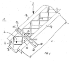
- FIG. 1 shows a base support 1, which is arranged for example between two non-illustrated edge regions of a vehicle structure.
- the base support 1 is arranged as a so-called instrument carrier between two A-pillars of a vehicle.
- the base support 1 comprises a hollow profile 2.
- the hollow profile 2 is formed as a U or ⁇ profile.
- the hollow profile 2 may be formed as a hollow cylinder.
- the hollow profile 2, also called support profile consists of a first material, in particular of metal, for example of steel, aluminum, magnesium or copper.
- the profile core 8 is inserted in the form of an inner ribbing for stiffening the hollow profile 2 in the cavity 6.
- the profile core 8 is formed in the embodiment as a honeycomb core or rhombic core.
- the profile core 8 extends substantially over the entire length L, width B and height H of the cavity 6 of the hollow section 2.
- the profile core 8 can be segmented over the length L of the hollow profile 2, by depending on the predetermined Aussteifungsgrad the profile core 8 is alternately rhomboid or honeycomb-shaped.
- the profile core 8 may also have a different shape, e.g. Z-shaped extending ribs have.
- the base support 1 For function-specific cultivation of vehicle components, such as Airbag, steering, holders or struts, the base support 1, a holding element 12 that is attached to the hollow profile 2 via a cavity 6 inserted in the form-fitting and / or cohesive joint connection 10.
- the holding element 12 is further arranged the cavity 6 bridging the hollow profile 2. That the holding element 12 connects the two legs 4 of the hollow profile 2.
- the holding element 2 is located on projections 14 of the legs 4 area.
- the holding element 12 is designed to planar or planar.
- the holding element 12 has a recess 16.
- the recess 16 is adapted in its dimensions to a cavity 6 representing the opening, in particular to the shape thereof.
- the holding element 12 may for example also be formed by a U, H, L, W or Z profile.
- the positive joining connection 10 of the holding element 12 is formed by below by means of the recess 16 webs 18 rib-shaped in the cavity 6 joined.
- this may be U-shaped or box-shaped.
- both the u- or box-shaped joint connection 10 and the box-shaped hollow profile 2 are joined together like a box.
- the closed side of the box-shaped joint 10 is attached to the closed side of the hollow section 2.
- the open side of the box-shaped joint 10 and the hollow profile 2 point in the same direction.
- the box-shaped joint connection 10 is inserted vertically in the cavity 6.
- the hollow profile 2 in particular its opening, may be provided with a cover, not shown. That the height of the profile core 8 corresponds to the height of the cavity 6.
- the planar design holding element 12 is particularly easy to position on the surface, in particular the projections 14 of the legs 4.
- the base support 1 is formed in hybrid construction.
- the hollow section 2 of the first material for. As steel, aluminum or magnesium
- the holding member 12 made of a second material, for. As thermoplastic, for the formation of different holders, but also to reinforce the stiffening function.
- the holding member 12 may also be formed of metal or other elastic material.
- the profile core 8 is made of a third material, for. As plastic, be formed.
- the profile core 8 may be formed of another easily moldable material, eg also of a metal.
- the profiled core 8 is formed in particular for a non-detachable connection, in particular joint connection, with the hollow profile 2 of malleable plastic.
- the holding element 12 may, depending on the desired rigidity of a metal, in particular of a material with so-called be formed high modulus.
- the retaining element 12 may also be formed from a moldable material, for example plastic.
- the individual components - hollow profile 2, profile core 8 and retaining element 12 - may be formed from any combination of different materials depending on the desired stiffness.
- the base support 1 may be formed as a thermoplastic injection molding hybrid or as a metal-metal hybrid.
- the profile core 8 projects at least partially beyond the cavity 6 out of the hollow profile 2.
- the diamond-shaped profiled core 8 has an extension 20 extending in the direction of the z-axis.
- the extension 20 is formed as a z-shaped profile extending, bridge, bridge or strip.
- the extension 20 may have a matched to the profile core 8 course.
- the extension 20 also called reinforcement, on a width B of the cavity 6 beyond width, whereby the extension 20 'in the region of kinks of the z-shape on the Projections 14 rests.
- the profile core 8 may be formed with the extension 20 in one or more parts or layered.
- the extension 20 is arranged in particular in the region between two holding elements 12 and divided into several sections.
- the extension 20 is made of a high modulus material, e.g. B. high strength steel.
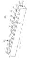
- FIG. 2B shows an alternative embodiment of a base support 1 with the inserted in the hollow section 2 profile core 8, which in turn is provided with the extension 20.
- the course of the extension 20 seen in the longitudinal direction of the hollow profile 2 approximately corresponds to the course of the profile core 8.
- a plurality of spaced-apart fasteners 22, eg L-angle provided for fastening the extension 20 on the hollow profile 2 seen in the longitudinal direction of the hollow profile a plurality of spaced-apart fasteners 22, eg L-angle provided.
- the extension 20 has over the diamond shape of the profile core 8 a z-shaped course.
- the extension 20 in cross section has the same shape as the profile core 8. Both are diamond-shaped. Instead of a separate holding element forms in this embodiment, at least a portion of the extension 20, the holding element 12. For this purpose, the extension 20 is executed for example in a rhombus on the profile core 8 outstanding and shaped the desired holding function accordingly.
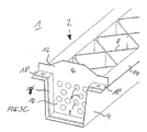
- FIG. 3A and 3B show a further embodiment of a base support 1 with a rib-shaped holding element 12 in cross-section and in perspective view.
- the holding element 12 is formed by a single inserted into the cavity 6 rib 24.
- the rib 24 may have a thickness or wall thickness of 1.2 mm to 3.5 mm in injection molding or from 5 to 15 mm in foam casting.
- the rib 24 has on the pointing into the cavity 6 underside a claw 25 in the form of a rhombus. As a result, an improved adhesive bond between the retaining element 12 and the inserted profile core 8 is effected.
- FIG. 3B shows the base support 1 in a perspective view.
- FIG. 3C shows an alternative embodiment for a rib 24.
- the rib 24 is executed perforated.
- the rib 24 may be formed for a particularly good fit in the hollow section 2 as an L-profile.
- the short leg of the rib 24 extends as a web 18 'flat along the inside of the hollow section. 2
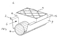
- FIG. 4 shows an alternative embodiment of a base support 1 with an integrated guide member 26, such as an air guide, and with the integrated support member 12.
- the stiffening of the hollow profile 2 causing profile core 8, which in the cavity 6 to the guide element 26 is positively and / or cohesively joined, not shown in detail for clarity.
- the FIG. 5 shows a further embodiment of a base support 1 with an integrated guide member 26 and attached thereto profile core 8 and retaining element 12th
- the hollow profile 2 and the support member 12 are joined together by arching the form-fitting joint connection 10 with each other.
- the retaining element 12 to be fastened to the U-shaped or ⁇ -shaped hollow profile 2 can be pre-positioned or prefixed.
- the holding element 12 eg bulkheads or reinforcing plates, in known fastening techniques, such as by bending, rolling, crimping, plugging, cabinets, beads or clinching prefixed to the hollow section 2.
- the holding element 12 is formed of metal.
- metal retaining members 12 may be used as fixing techniques, eg, welding, riveting, gluing, soldering for prefixing.
- the hollow profile 2 and the holding element 12 are joined together by the form-fitting and / or material connection by the profile core 8 performing a connecting function.
- the profile core 8 is brought by prototyping in a mold in the form.
- the hollow section 2 and the holding element 12 are already arranged for this purpose; the profile core 8 is introduced by primary molding, in particular injection molding, foam casting, polyamide casting, TSG, Thixoforming, foaming or pressing.
- all three elements - hollow profile 2, retaining element 12 and profile core 8 - made separately and joined together.
- the individual elements - hollow profile 2, retaining element 12 and profile core 8 - again be designed in several parts.
Abstract
Description
Die Erfindung betrifft einen Grundträger zwischen zwei Randbereichen einer Fahrzeugstruktur. Des Weiteren betrifft sie ein Verfahren zur Herstellung eines derartigen Grundträgers.The invention relates to a base support between two edge regions of a vehicle structure. Furthermore, it relates to a method for producing such a basic carrier.
Grundträger, z.B. Instrumententräger, erstrecken sich üblicherweise zwischen zwei Randbereichen einer Fahrzeugstruktur, beispielsweise im Bereich zwischen den beiden vorderen A-Säulen quer zur Fahrzeuglängsachse. Ein derartiger Grund-, insbesondere Instrumententräger besteht im Wesentlichen aus einem Tragprofil, insbesondere einem Hohlprofil, welches üblicherweise in Hybridbauweise hergestellt wird. Bei einer Hybridbauweise wird eine längliche Metallschale, die gewöhnlich in U- oder Q-Form ausgeprägt ist, von der offenen Seite mit einer Verstärkung, insbesondere einer inneren Verrippung eines anderen Materials, z.B. Kunststoff, ausgebildet. Die innere Verrippung wird dabei üblicherweise durch einen Urformprozess, z.B. Spritzguss- oder Schaumgussverfahren, gefügt.Basic carrier, e.g. Instrument carrier, usually extend between two edge regions of a vehicle structure, for example in the area between the two front A-pillars transverse to the vehicle longitudinal axis. Such a basic, in particular instrument carrier consists essentially of a support profile, in particular a hollow profile, which is usually produced in hybrid construction. In a hybrid construction, an elongated metal shell, usually in U or Q form, is reinforced from the open side with a reinforcement, in particular an inner ribbing of another material, e.g. Plastic, formed. The inner ribbing is usually done by a prototyping process, e.g. Injection molding or foam casting process, joined.
Die in der Metallschale oder dem Hohlprofil eingefügte Verrippung, auch Profilkern genannt, wird entsprechend auftretenden Belastungen ausgebildet. Beispielsweise wird der Profilkern durch rautenförmig angeordnete Rippen ausgebildet. Darüber hinaus ist es möglich in den Profilkern oder die Verrrippung ein Rohr zur Luftführung, z.B. für eine Klimaanlage, einzubringen. Dies ist beispielsweise aus der
Darüber hinaus kann an den Profilen mindestens ein Halteelement zur Anbindung von Funktionselementen vorgesehen sein. Dabei werden die Halteelemente üblicherweise nach dem eigentlichen Einfügungsprozess des Profilkerns an das Hohlprofil angebracht, z. B. genietet, geschweißt oder geschraubt. Nachteilig dabei ist, dass zusätzliche Teile für den Zusammenbau des Grundträgers benötigt werden. Ferner müssen die verschiedenen Halteelemente oder Anschlüsse teilweise in einzelnen Arbeitsgängen mit verschiedenartigen Fügeoperationen an dem Träger befestigt oder verbunden werden, wodurch sich die Anzahl der Arbeitsgänge nochmals erhöht.In addition, at least one holding element for connecting functional elements can be provided on the profiles. The holding elements are usually attached after the actual insertion process of the profile core to the hollow profile, z. B. riveted, welded or screwed. The disadvantage here is that additional parts are needed for the assembly of the base support. Furthermore, the various holding elements or connections must be partially attached or connected in individual operations with various joining operations on the carrier, whereby the number of operations increases again.
Aus der
Ferner zeigt die
Des weiteren zeigt die
Der Erfindung liegt daher die Aufgabe zugrunde, einen Grundträger zwischen zwei Randbereichen einer Fahrzeugstruktur anzugeben, welcher besonders einfach ausgebildet ist und eine gegenüber dem Stand der Technik verbesserte Struktur aufweist. Weiterhin soll ein Verfahren zur Herstellung eines derartigen Grundträgers angegeben werden, welches besonders einfach und kostengünstig ausgestaltet ist.The invention is therefore based on the object of specifying a base support between two edge regions of a vehicle structure, which is particularly simple in construction and has an improved structure compared to the prior art. Furthermore, a method for producing such a base support is to be specified, which is designed particularly simple and inexpensive.
Die Aufgabe wird gelöst durch einen Grundträger gemäß Anspruch 1, sowie durch ein Verfahren gemäß Anspruch 23.The object is achieved by a base support according to
Der Grundträger umfasst ein Hohlprofil und wenigstens ein Halteelement zur Anbindung von Funktionselementen, bei dem das Halteelement über eine im Hohlraum eingefügte formschlüssige und/oder stoffschlüssige Fügeverbindung an das Hohlprofil befestigt ist.The base carrier comprises a hollow profile and at least one holding element for connecting functional elements, in which the holding element is fastened to the hollow profile via a form-fitting and / or material-fit joint connection inserted in the cavity.
Die Erfindung geht dabei von der Überlegung aus, dass ein Grundträger zur Anbringung zwischen zwei Randbereichen einer Fahrzeugstruktur derart ausgebildet sein sollte, dass er den Erfordernissen und den technologischen Anforderungen der Industrie angepasst ist. Ein herkömmlicher Grundträger weist aufgrund größerer Wanddicken des zugehörigen Trag- oder Hohlprofils zur Erhöhung der Steifigkeit ein erhöhtes Gewicht auf, welches sich wiederum nachteilig auf den Kraftstoffverbrauch und somit auf die Umwelt auswirkt. Zur Reduzierung des hohen Gewichts sowie zur Verbesserung der Steifigkeit oder Festigkeit des Grundträgers sollte daher ein zur Anbindung von Funktionselementen vorgesehenes Halteelement derart an das Hohlprofil oder Tragprofil befestigt werden, dass dieses einen biege- und torsionssteifen Verbund mit dem Halteelement ermöglicht. Dazu ist das Halteelement über eine form- und/oder stoffschlüssige Fügeverbindung an das Hohlprofil befestigt. Mit anderen Worten: Das Halteelement ist in einem durch das Hohlprofil gebildeten Hohlraum form- und/oder stoffschlüssig eingefügt, indem das Halteelement und das Hohlprofil miteinander in einem einzigen Verarbeitungsschritt gefügt werden. Das Halteelement ist somit über eine innere Verbindung an das Hohlprofil befestigt.The invention is based on the consideration that a base support for attachment between two edge regions of a vehicle structure should be designed such that it is adapted to the requirements and the technological requirements of the industry. A conventional base support has due to greater wall thicknesses of the associated support or hollow profile to increase the rigidity of an increased weight, which in turn adversely affects fuel economy and thus the environment. In order to reduce the high weight and to improve the rigidity or strength of the base support should therefore be attached to the connection of functional elements holding member are fixed to the hollow profile or support profile, that this allows a bending and torsion-resistant composite with the support member. This is the holding element attached via a positive and / or cohesive joint connection to the hollow profile. In other words, the retaining element is positively and / or materially inserted in a cavity formed by the hollow profile by the retaining element and the hollow profile are joined together in a single processing step. The holding element is thus secured via an inner connection to the hollow profile.
Zum Schutz vor ungewolltem Lösen des gefügten Halteelements sowie für eine besonders hohe Stabilität der das Halteelement und das Hohlprofil miteinander verbindenden Fügeverbindung ist das Halteelement vorzugsweise durch sogenanntes Urformen form- und/oder stoffschlüssig gefügt. Dabei wird das Halteelement durch herkömmliche Urformverfahren, wie z.B. Ausgießen, Eingießen, Einvulkanisieren oder Einschäumen der Fügeverbindung unter Formschluss an das Hohlprofil gefügt bzw. befestigt. Zusätzlich kann das Halteelement durch sogenanntes Umformen, z.B. Nieten an das Hohlprofil befestigt sein. Mit anderen Worten: Das Halteelement kann über eine innere Verbindung, der Fügeverbindung und/oder eine äußere Verbindung, z.B. Clinchen oder Nieten, an das Hohlprofil befestigt.To protect against unwanted loosening of the joined retaining element and for a particularly high stability of the retaining element and the hollow profile interconnecting joint connection, the retaining element is preferably form-fitting and / or materially joined by so-called archetypes. In this case, the holding element is replaced by conventional primary shaping methods, such as e.g. Pouring, pouring, vulcanization or lathering of the joint connection under positive engagement joined or fastened to the hollow profile. In addition, the retaining element may be formed by so-called forming, e.g. Rivets to be attached to the hollow profile. In other words, the holding element can be connected via an inner connection, the joint connection and / or an outer connection, e.g. Clinching or riveting, attached to the hollow profile.
In Abhängigkeit von an dem Halteelementen anzubindenden Funktionselementen, wie z.B. Airbag, Lenkung, Halter oder Streben, ist das Halteelement einen das Hohlprofil repräsentierenden Hohlraum überbrückend angeordnet. Dabei ist zur Befestigung des Grundträgers an dessen Randbereichen der Fahrzeugstruktur das Halteelement an den Seitenenden des Hohlprofils und demzufolge den Hohlraum an einer Seitenfläche überbrückend angeordnet. Bei einem als Instrumententräger dienenden Grundträger sind auf dem Hohlprofil mehrere Halteelemente zur Anbringung von Instrumenten, wie z.B. Anzeigen, vorgesehen, wobei das Halteelement den Hohlraum an einer Oberfläche, insbesondere Ober- und/oder Unterseite, überbrückt.Depending on functional elements to be bonded to the support member, e.g. Airbag, steering, holder or struts, the holding element is arranged bridging a hollow profile representing the cavity. In this case, the retaining element at the side ends of the hollow profile and consequently the cavity on a side surface bridging arranged for attachment of the base support at the edge regions of the vehicle structure. In a base carrier serving as an instrument carrier, a plurality of holding elements for attaching instruments, such as e.g. Displays, provided, wherein the holding element bridges the cavity on a surface, in particular top and / or bottom.
Für eine besonders einfache Fügung des Halteelementes an das Hohlprofil weist dieses eine Aussparung auf. Zweckmäßigerweise entspricht die Länge der Aussparung oder Öffnung in etwa der Breite des Hohlraumes. Je nach Anordnung des Halteelements an das Hohlprofil, z.B. auf dessen Oberfläche oder einer der Seitenflächen sind die Abmessungen der Aussparung am betreffenden Querschnitt bzw. Längsschnitt des Hohlraumes angepasst. Die Aussparung oder Öffnung ermöglicht in besonders einfacher Art und Weise die Einführung eines Werkzeuges, z.B. eines Stempels zur Herstellung der Fügeverbindung beim Spritz- oder Gießprozess. Somit ist eine Materialanhäufung unter dem anzubindenden Halteelement beim Herstellen der Fügeverbindung sicher vermieden.For a particularly simple joining of the holding element to the hollow profile, this has a recess. Conveniently, the length of the recess or opening corresponds approximately to the width of the cavity. Depending on the arrangement of the retaining element to the hollow profile, for example on the surface or one of the side surfaces, the dimensions of the recess on the relevant Cross section or longitudinal section of the cavity adjusted. The recess or opening allows in a particularly simple manner, the introduction of a tool, such as a punch for producing the joint during the injection or casting process. Thus, an accumulation of material under the holding element to be connected during manufacture of the joint connection is reliably avoided.
Zur weiteren Gewichtsreduzierung des Grundträgers sowie zur verbesserten Aussteifung des Hohlraumes ist das Halteelement unterhalb von mittels der Aussparung gebildeten Stegen anhand von im Hohlraum eingefügten Rippen gefügt. Hierdurch sind bei sich eigentlich widersprechenden Anforderungen - einer vergleichsweise geringen Rippendicke unter gleichzeitiger Aufrechterhaltung einer hohen Steifigkeit - eine besonders hinreichende Verzugsarmut und Torsionssteifigkeit durch die als Rippen ausgebildete formschlüssige Fügeverbindung des Halteelements im Hohlraum des Hohlprofils gegeben. Je nach gewünschter Steifigkeit oder Gewichtsreduzierung kann eine einzelne Rippe oder mehrere Rippen im Hohlraum des Hohlprofils angeordnet sein. Für ein verbessertes Torsionsverhalten weist die Rippe einen sogenannten Hinterschnitt auf. Mit anderen Worten: Die Rippe ist mit einer Verkrallung versehen. In einer bevorzugten Ausführungsform weist die Rippe im Längsschnitt zumindest an der in den Hohlraum angeordneten Unterseite eine Mäanderform auf. Die andere Seite, insbesondere über den Hohlraum herausragende Oberseite der Rippe kann dabei derart geformt und mit einer Aussparung versehen sein, dass diese als Halteelement dient. Für einen besonders guten Verbund, z.B. Blech-Kunststoff-Verbund des als Blech ausgebildeten Hohlprofils und der Kunststoffrippe bzw. dem Kunststoffprofil, ist die Rippe gelocht ausgeführt.For further weight reduction of the base support and for improved stiffening of the cavity, the holding element is joined below formed by means of the recess webs based on inserted into the cavity ribs. As a result, with actually contradictory requirements - a comparatively small rib thickness while maintaining a high rigidity - a particularly sufficient Verzugsarmut and torsional stiffness given by the formed as ribs form-fitting joint connection of the holding element in the cavity of the hollow profile. Depending on the desired rigidity or weight reduction, a single rib or a plurality of ribs may be arranged in the hollow space of the hollow profile. For improved torsional behavior, the rib has a so-called undercut. In other words, the rib is clawed. In a preferred embodiment, the rib has a meandering shape in longitudinal section at least on the underside arranged in the cavity. The other side, in particular over the cavity protruding top of the rib can be shaped and provided with a recess that it serves as a holding element. For a particularly good composite, e.g. Sheet-plastic composite formed as a sheet metal hollow profile and the plastic rib or the plastic profile, the rib is perforated.
Um eine gegenüber der rippenartigen Fügeverbindung verbesserte Steifigkeit oder Festigkeit des Hohlprofils zu erzielen, ist zweckmäßigerweise das Halteelement unterhalb von mittels der Aussparung gebildeten Stegen anhand eines im Hohlraum eingefügten U-Profils gefügt. Das U-Profil wird dabei schachtelartig im Hohlraum des ebenfalls u-förmigen Hohlprofils eingefügt. Durch eine eine derartige Querbrücke oder einen offenen Querkasten bildenden Fügeverbindung, welche im Hohlraum des Hohlprofils eingefügt ist, ist das Hohlprofil zusätzlich gegen mechanische Beanspruchungen, z.B. Beulen, geschützt. Je nach Funktion und Art der am Grundträger zu befestigenden Instrumente und der daraus resultierenden Anzahl von am Hohlprofil zu befestigenden Halteelementen kann die Fügeverbindung verschiedenartig, rippen- oder kastenförmig ausgebildet sein.In order to achieve an improved stiffness or strength of the hollow profile relative to the rib-like joint connection, the retaining element is expediently joined below webs formed by means of the recess on the basis of a U-profile inserted in the cavity. The U-profile is thereby inserted like a box in the cavity of the likewise U-shaped hollow profile. By a such transverse bridge or an open transverse box forming joint connection, which inserted in the cavity of the hollow profile is, the hollow section is additionally protected against mechanical stresses, such as bumps. Depending on the function and type of instruments to be fastened to the base support and the resulting number of holding elements to be fastened to the hollow profile, the joint connection can be designed in various shapes, ribs or boxes.
Für eine Grundaussteifung des Hohlprofils ist zweckmäßigerweise dieses im Hohlraum mit einem Profilkern versehen. Bevorzugt ist der Profilkern durch Umformen formschlüssig in den Hohlraum gefügt. Als besonders vorteilhafte Ausführungsform des Profilkerns ist dieser als Wabenkern, Rautenkern oder Verrippung ausgebildet. Der Profilkern ist dabei insbesondere quer oder schräg in den Hohlraum des Hohlprofils für eine besonders gute Aussteifung eingefügt. Je nach Orientierung der Rippen, z.B. Rauteform, ergibt sich eine besonders gute Biege- oder Torsionssteifigkeit.For a basic stiffening of the hollow profile, this is expediently provided in the cavity with a profile core. Preferably, the profile core is positively joined by forming in the cavity. As a particularly advantageous embodiment of the profile core this is designed as a honeycomb core, Rautenkern or ribbing. The profile core is in particular transversely or obliquely inserted into the cavity of the hollow profile for a particularly good stiffening. Depending on the orientation of the ribs, e.g. Rough shape, results in a particularly good bending or torsional rigidity.
Je nach Anwendung und Funktion des Grundträgers ist das Hohlprofil zweckmäßigerweise als U- oder Ω-Profil ausgebildet. Alternativ kann das Hohlprofil als Hohlzylinder ausgebildet sein. Bei einem U-förmigen und somit zu einer Oberfläche hin offenen Hohlprofil ist das Halteelement in einer die beiden Schenkel des Hohlprofils verbindenden Anordnung und somit die Öffnung des Hohlraumes überbrückenden Anordnung an das Hohlprofil befestigt. Zur Verstärkung der Aussteifung oder Festigkeit des Hohlprofils ragt der Profilkern zweckmäßigerweise über eine Öffnung des Hohlraumes hinaus. Alternativ oder zusätzlich kann das Hohlprofil, insbesondere dessen Öffnung, mit einem Deckel versehen sein. In einer bevorzugten Ausführungsform entspricht die Höhe des Profilkerns der Höhe des Hohlraumes. Hierdurch ist das planar ausgebildete Halteelement besonders einfach auf der Oberfläche des Hohlprofils positionierbar. Darüber hinaus weist der Profilkern in etwa die gleichen Abmessungen des Hohlraumes auf. D.h. der Profilkern erstreckt sich über die gesamte Länge, Breite und Höhe des Hohlraumes und schließt mit dessen Oberflächen ab. Alternativ oder zusätzlich kann der Profilkern im Bereich zwischen zwei Halteelementen aus dem Hohlraum hinausragen.Depending on the application and function of the basic carrier, the hollow profile is expediently designed as a U or Ω profile. Alternatively, the hollow profile may be formed as a hollow cylinder. In the case of a U-shaped hollow profile which is thus open towards a surface, the retaining element is fastened to the hollow profile in an arrangement connecting the two limbs of the hollow profile and thus bridging the opening of the hollow space. To reinforce the stiffening or strength of the hollow profile of the profile core protrudes expediently beyond an opening of the cavity. Alternatively or additionally, the hollow profile, in particular its opening, be provided with a lid. In a preferred embodiment, the height of the profile core corresponds to the height of the cavity. As a result, the planar design holding element is particularly easy to position on the surface of the hollow profile. In addition, the profile core has approximately the same dimensions of the cavity. That is, the profile core extends over the entire length, width and height of the cavity and terminates with its surfaces. Alternatively or additionally, the profiled core may protrude from the cavity in the area between two retaining elements.
In einer weiteren bevorzugten Ausführungsform des Grundträgers ist dieser in Hybridbauweise ausgebildet, wobei das Hohlprofil aus einem ersten Material und das Halteelement aus einem zweiten Material gebildet sind. Ein derartiger in Hybridbauweise ausgebildeter Grundträger weist eine besonders hohe Steifigkeit bei gleichzeitig einer festen und möglichst leichten Bauweise auf. Das Hohlprofil ist dabei aus Metall, z.B. Stahl, Aluminium, Kupfer, Magnesium gebildet. Das die Versteifungsfunktion verstärkende Halteelement ist bevorzugt aus thermoplastischem Kunststoff gebildet. Alternativ kann das Halteelement aus einem Metall oder einem anderen elastischen Material gebildet sein. Je nach der für die zugrunde liegenden Funktion erforderlichen Festigkeit oder Steifigkeit kann der Kunststoff mit oder ohne Füll- und Verstärkungsstoffe versehen sein. Als thermoplastische Kunststoffe werden beispielsweise Polyamide, Polyolefine, Styrole oder andere Ein- oder Mehrkomponentenkunststoffe, wie z.B. PU-Harze, verwendet werden.In a further preferred embodiment of the basic carrier of this is designed in hybrid construction, wherein the hollow profile of a first material and the holding element are formed of a second material. Such a constructed in hybrid construction basic carrier has a particularly high rigidity at the same time a solid and lightweight construction possible. The hollow profile is made of metal, e.g. Steel, aluminum, copper, magnesium formed. The stiffening function reinforcing retaining element is preferably formed of thermoplastic material. Alternatively, the holding member may be formed of a metal or other elastic material. Depending on the strength or stiffness required for the underlying function, the plastic may be provided with or without fillers and reinforcing materials. As thermoplastics, for example, polyamides, polyolefins, styrenes or other single- or multi-component plastics, such. PU resins, to be used.
Bei einer Mehrfachverwendung des Grundträgers, z.B. sowohl zur Luftführung als auch zur Halterung von Komponenten, ist zweckmäßigerweise in das Hohlprofil ein Führungselement, z.B. eine Luftführung integriert, an welche das Halteelement und/oder der Profilkern form- und/oder stoffschlüssig gefügt sind.In a multiple use of the basic carrier, e.g. both for air guidance and for holding components, is expediently in the hollow profile, a guide element, e.g. an air guide integrated, to which the holding element and / or the profile core are positively and / or cohesively joined.
Die bezüglich des Verfahrens zur Herstellung eines derartigen Grundträgers genannte Aufgabe wird erfindungsgemäß gelöst, indem ein Hohlprofil und wenigstens ein Halteelement zur Anbindung von Funktionselementen über eine im Hohlraum des Hohlprofils durch Urformen eingebrachte Fügeverbindung formschlüssig miteinander gefügt werden. Mit anderen Worten: Der Grundträger wird in Hybridbauweise aus zwei oder mehreren Einzelteilen gebildet - dem Hohlprofil und wenigstens einem Halteelement, welche aus unterschiedlichem oder gleichem Material gebildet sein können. Über eine durch Urformen gebildete und im Hohlraum eingefügte formschlüssige Fügeverbindung (= Innenverbindung), welche ein weiteres Material aufweist, werden das Hohlprofil und das Halteelement miteinander gefügt. Der Vorteil dieser durch Urformen hergestellten Fügeverbindung besteht darin, dass das Hohlprofil mit dem Halteelement in einem einzigen Arbeitsschritt zum Grundträger gefertigt werden kann.The object mentioned with regard to the method for producing such a basic carrier is achieved according to the invention by form-fitting a hollow profile and at least one holding element for connecting functional elements to one another by means of a joining connection introduced in the hollow space of the hollow profile by prototyping. In other words: The basic carrier is formed in hybrid construction of two or more individual parts - the hollow profile and at least one holding element, which may be formed of different or the same material. About a formed by Urformen and inserted in the cavity positive connection (= inner joint), which has a further material, the hollow profile and the holding element are joined together. The advantage of this joint connection produced by prototyping is that the Hollow profile can be manufactured with the holding element in a single step to the base support.
Als Verfahren zur Herstellung eines ein Hohlprofil mit integriertem Halteelement aufweisenden Grundträgers durch eine formschlüssige Fügeverbindung der Elemente eignen sich insbesondere herkömmliche Spritzgießverfahren oder Gießverfahren mit anschließender Polymerisation, z.B. ein Polyamid-Guss, Schäum- oder Spritzverfahren, Schaumgießverfahren, insbesondere Polyurethan-Schaum-Verfahren, z.B. Thermoplast-Schaum-Guss (kurz TSG genannt). Durch die Verwendung der vorgenannten Verfahren bei einem wenigstens eine Stufe aufweisenden Verarbeitungsprozess ist der Vorteil gegeben, dass andere aufwändige Fertigungsprozesse zur Anbindung der Halteelemente entfallen können. Insbesondere ist die Anzahl von Verarbeitungsschritten zur Herstellung des Grundträgers deutlich reduziert. Auch sind aufwendige und somit kostenintensive Werkzeuge zur Befestigung des Halteelements sicher vermieden.As a method for producing a base carrier having a hollow profile with an integrated holding element by means of a positive joining connection of the elements, conventional injection molding methods or casting methods with subsequent polymerization, e.g. a polyamide casting, foaming or spraying process, foam casting process, in particular polyurethane foam process, e.g. Thermoplastic foam casting (TSG for short). By using the aforementioned method in a processing process having at least one stage, there is the advantage that other complicated production processes for connecting the holding elements can be dispensed with. In particular, the number of processing steps for producing the base carrier is significantly reduced. Also costly and therefore costly tools for attaching the retaining element are avoided.
In einer bevorzugten Ausführungsform des Herstellungsverfahrens wird das Halteelement während des Fügeprozesses beim Urformen selbst geformt und in das Hohlprofil gefügt. Hierbei weist das Halteelement das selbe Material auf wie ein ebenfalls durch den Fügeprozess zur Versteifung in das Hohlprofil eingefügter Profilkern. Der Vorteil dieses Herstellungsverfahrens liegt darin, dass die endgültige Position des Halteelementes durch das im Fertigungsprozess genutzte Werkzeug festgelegt wird. Hierdurch ist eine höhere Genauigkeit mit einem besonders engen Toleranzbereich ermöglicht. Alternativ zum während des Verarbeitungsprozesses geformten Halteelementes kann das Halteelement vorgefertigt sein. Zweckmäßigerweise wird dabei das Halteelement vor dem Verarbeitungsprozess am Hohlprofil positioniert und währenddessen formschlüssig durch Urformen an das Hohlprofil gefügt (= Außenverbindung). Für eine derartige Vorfixierung oder Positionierung des Halteelementes am Hohlprofil werden bekannte Umform-Verfahren, wie z.B. Biegen, Walzen, Bördeln, Durchstecken, Schränken, Sicken, Clinchen, verwendet. Bei aus Metall gebildeten Halteelementen werden zur Vorfixierung bekannte Fügeverfahren, wie z.B. Schweißen, Nieten, Löten, Clinchen, verwendet.In a preferred embodiment of the production method, the holding element is formed during the joining process in the prototyping itself and joined in the hollow profile. Here, the holding element has the same material as a likewise inserted by the joining process for stiffening in the hollow profile core. The advantage of this manufacturing method is that the final position of the holding element is determined by the tool used in the manufacturing process. As a result, a higher accuracy is possible with a particularly narrow tolerance range. As an alternative to the holding element formed during the processing process, the holding element can be prefabricated. Conveniently, the holding element is positioned before the processing process on the hollow profile and while form-fitting joined by prototyping to the hollow profile (= external connection). For such prefixing or positioning of the holding element on the hollow profile known forming methods, such as bending, rolling, flanging, insertion, cabinets, beads, clinching, are used. In the case of holding elements formed from metal, known joining methods such as welding, riveting, soldering, clinching are used for prefixing.
Des Weiteren lassen sich in Abhängigkeit vom anzuwendenden Fügeverfahren die Einzelteile - das Hohlprofil und das Halteelement, insbesondere wenn diese aus Metall ausgebildet sind - vor oder nach dem Fügeverfahren oberflächenbehandeln. Hierbei werden die Oberflächen des Grundträgers und dessen Elemente beispielsweise lackiert oder beschichtet. Als zur Vorfixierung am besten geeignete Fügeverfahren wird vorteilhaft dasjenige Verfahren, z.B. Clinchen oder Stanznieten, ausgewählt, bei dem die formschlüssige Fügeverbindung durch Urformen und die Vorfixierung durch Umformen durch ein einziges Werkzeug selbst ausgeführt werden kann. Beispielsweise kann durch die Schließbewegung des Werkzeuges, insbesondere eines Spritzwerkzeuges, das. Halteelement durch Clinchen oder Stanznieten erst vorfixiert werden und anschließend durch Ausgießen der Fügeverbindung formschlüssig gefügt werden. Ein derartiges Verfahren hat den Vorteil, dass die Bauteilposition der Einzelteile, insbesondere der Halteelemente, durch das Werkzeug selbst festgelegt wird. Zweckmäßigerweise wird der Profilkern und/oder das Halteelement beim Urformen als Spritzguss-Werkstück spritzgegossen oder schaumgegossen.Furthermore, depending on the joining method to be used, the individual parts-the hollow profile and the retaining element, in particular if they are made of metal-can be surface-treated before or after the joining process. Here, the surfaces of the base support and its elements, for example, painted or coated. As the prefixing most suitable joining method is advantageously that method, e.g. Clinching or punching rivets, selected in which the positive joining connection can be carried out by prototyping and the prefixing by forming by a single tool itself. For example, by the closing movement of the tool, in particular an injection molding tool, the. Retaining element can be prefixed by clinching or stamping rivets and then joined positively by pouring the joint connection. Such a method has the advantage that the component position of the individual parts, in particular the holding elements, is determined by the tool itself. Appropriately, the profile core and / or the retaining element is injection-molded or foam-molded during molding as an injection-molded workpiece.
Die mit der Erfindung erzielten Vorteile bestehen insbesondere darin, dass durch ein über eine formschlüssige Fügeverbindung im Hohlraum des Hohlprofils befestigten Halteelement ein besonders einfacher und formstabiler sowie torsionssteifer Grundträger ermöglicht ist, der gleichzeitig ein besonders geringes Eigengewicht aufweist und besonders einfach zu fertigen ist. In der bevorzugten Ausführungsform wird das Halteelement beim Fügen im Spritzguss-Werkzeug selbst geformt und in das Hohlprofil eingefügt. Alternativ kann das Halteelement und das Hohlprofil vor dem Urformprozess, insbesondere Spritzprozess, ins Werkzeug eingebracht werden und wirtschaftlich in einem einzigen Schritt zu einer fertigen Baugruppe zusammengebracht werden (sogenanntes In-Mould-Assembly-Verfahren).The advantages achieved by the invention are in particular that a particularly simple and dimensionally stable and torsionally rigid base support is made possible by a via a positive joining connection in the cavity of the hollow profile holding element, which at the same time has a particularly low weight and is particularly easy to manufacture. In the preferred embodiment, the holding element is formed during joining in the injection molding tool itself and inserted into the hollow profile. Alternatively, the holding element and the hollow profile can be introduced into the mold before the primary molding process, in particular injection molding process, and brought together economically in a single step to form a finished assembly (so-called in-mold assembly method).
Ausführungsbeispiele der Erfindung werden anhand einer Zeichnung näher erläutert. Darin zeigen:
Figur 1- schematisch einen Grundträger mit einem Hohlprofil und wenigstens einem Halteelement zur Anbindung von Funktionselementen in perspektivischer Darstellung,
- Figur 2A bis 2C
- schematisch alternative Ausführungsformen für einen Grundträger mit einem Hohlprofil und einem über die Höhe des Hohlprofils verlängerten Profilkern in perspektivischer Darstellung,
- Figuren
- 3A bis 3C schematisch im Querschnitt bzw. in perspektivischer Darstellung eine weitere Ausführungsform für einen Grundträger mit einem rippenförmigen Halteelement,
Figur 4- schematisch eine weitere Ausführungsform für einen Grundträger mit einem integrierten Führungselement und einem eingefügten Profilkern, und
- Figur 5
- schematisch eine weitere Ausführungsform für einen Grundträger mit einem integrierten Führungselement und einem eingefügten Profilkern sowie einem Halteelement.
- FIG. 1
- 2 schematically shows a basic carrier with a hollow profile and at least one holding element for connecting functional elements in a perspective view;
- FIGS. 2A to 2C
- schematically alternative embodiments for a base support with a hollow profile and a lengthened over the height of the hollow profile core in perspective,
- characters
- 3A to 3C schematically in cross-section and in perspective another embodiment for a base support with a rib-shaped holding element,
- FIG. 4
- schematically a further embodiment of a base support with an integrated guide element and an inserted profile core, and
- FIG. 5
- schematically another embodiment of a base support with an integrated guide element and an inserted profile core and a holding element.
Einander entsprechende Teile sind in allen Figuren mit den gleichen Bezugszeichen versehen.Corresponding parts are provided in all figures with the same reference numerals.
Der Grundträger 1 umfasst ein Hohlprofil 2. Das Hohlprofil 2 ist als U- oder Ω-Profil ausgebildet. Alternativ kann das Hohlprofil 2 als Hohlzylinder ausgebildet sein. Das Hohlprofil 2, auch Trägerprofil genannt, besteht aus einem ersten Material, insbesondere aus Metall, z.B. aus Stahl, Aluminium, Magnesium oder Kupfer. Das aus einem derartigen ersten Material gebildete Hohlprofil 2 ist ein sogenanntes hohes E-Modul (= Elastizitäts-Modul) mit einer hohen Steifigkeit bei einer besonders geringen Dichte. Das in U- oder Ω-Form ausgeprägte Hohlprofil 2 (auch längliche Metallschale genannt) ist in einem zwischen den Schenkeln 4 des Hohlprofils 2 gebildeten Hohlraum 6 mit einem Profilkern 8 versehen.The
Der Profilkern 8 ist in der Form einer inneren Verrippung zur Aussteifung des Hohlprofils 2 in dessen Hohlraum 6 eingefügt. Der Profilkern 8 ist im Ausführungsbeispiel als Wabenkern oder Rautenkern ausgebildet. Der Profilkern 8 erstreckt sich dabei im wesentlichen über die gesamte Länge L, Breite B und Höhe H des Hohlraumes 6 des Hohlprofils 2. Des Weiteren kann der Profilkern 8 über die Länge L des Hohlprofils 2 segmentiert sein, indem in Abhängigkeit vom vorgegebenen Aussteifungsgrad der Profilkern 8 abwechselnd rauten- oder wabenförmig ausgebildet ist. Je nach Aussteifungs- oder Festigkeitsgrad kann der Profilkern 8 auch eine andere Form, z.B. Z-förmig verlaufende Rippen, aufweisen.The
Zum funktionsspezifischen Anbau von Fahrzeugkomponenten, wie z.B. Airbag, Lenkung, Haltern oder Streben, weist der Grundträger 1 ein Halteelement 12 auf, dass an das Hohlprofil 2 über eine im Hohlraum 6 eingefügte form- und/oder stoffschlüssige Fügeverbindung 10 befestigt ist. Das Halteelement 12 ist des Weiteren den Hohlraum 6 überbrückend an das Hohlprofil 2 angeordnet. D.h. das Halteelement 12 verbindet die beiden Schenkel 4 des Hohlprofils 2. Hierzu liegt das Halteelement 2 auf Auskragungen 14 der Schenkel 4 flächig auf. Das Halteelement 12 ist dazu flächig oder planar ausgebildet. Zusätzlich zur Innenverbindung des Halteelements 12 mittels der im Hohlraum 6 eingefügten Fügeverbindung 10 kann das Halteelement 12 beispielsweise mittels Toxen, Clinchen oder Nieten am Hohlprofil 2, z.B. an Ausnehmungen 15 an den Auskragungen 14 fixiert werden (= Außenverbindung).For function-specific cultivation of vehicle components, such as Airbag, steering, holders or struts, the
Des Weiteren weist das Halteelement 12 eine Aussparung 16 auf. Die Aussparung 16 ist dabei in ihren Abmessungen an eine den Hohlraum 6 repräsentierende Öffnung, insbesondere an deren Form angepasst. Dabei kann das Halteelement 12 beispielsweise auch durch ein U-, H-, L-, W- oder Z-Profil gebildet sein. Die formschlüssige Fügeverbindung 10 des Halteelements 12 ist durch unterhalb von mittels der Aussparung 16 gebildeten Stegen 18 rippenförmig im Hohlraum 6 gefügt. Alternativ zur rippenförmigen Ausbildung der formschlüssigen Fügeverbindung 10 kann diese u- oder kastenförmig ausgebildet sein. Dabei ist sowohl die u- oder kastenförmige Fügeverbindung 10 als auch das kastenförmige Hohlprofil 2 schachtelartig miteinander gefügt. Mit anderen Worten: Die geschlossene Seite der kastenförmigen Fügeverbindung 10 ist an die geschlossene Seite des Hohlprofils 2 angefügt. Die offene Seite der kastenförmigen Fügeverbindung 10 und des Hohlprofils 2 weisen in die selbe Richtung. Zur Aussteifung des Hohlprofils 2 ist die kastenförmige Fügeverbindung 10 senkrecht im Hohlraum 6 eingefügt.Furthermore, the holding
In Abhängigkeit von der Anzahl der anzubindenden Funktionselemente können auch mehrere Halteelemente 12 am Grundträger 1 befestigt sein. Im Bereich zwischen zwei Halteelementen 12 kann das Hohlprofil 2, insbesondere dessen Öffnung, mit einem nicht näher dargestellten Deckel versehen sein. D.h. die Höhe des Profilkerns 8 entspricht der Höhe des Hohlraumes 6. Hierdurch ist das planar ausgebildete Halteelement 12 besonders einfach auf der Oberfläche, insbesondere den Auskragungen 14 der Schenkel 4 positionierbar.Depending on the number of functional elements to be connected, it is also possible for a plurality of retaining
In einer bevorzugten Ausführungsform ist der Grundträger 1 in Hybridbauweise ausgebildet. Dazu ist das Hohlprofil 2 aus dem ersten Material, z. B. Stahl, Aluminium oder Magnesium, und das Halteelement 12 aus einem zweiten Material, z. B. thermoplastischen Kunststoff, zur Formung von verschiedenen Haltern, aber auch zur Verstärkung der Versteifungsfunktion. Alternativ kann das Halteelement 12 ebenfalls aus Metall oder einem anderen elastischen Material gebildet sein. Des Weiteren ist der Profilkern 8 aus einem dritten Material, z. B. Kunststoff, gebildet sein. Alternativ kann der Profilkern 8 aus einem anderen leicht formbaren Material, z.B. auch aus einem Metall gebildet sein. Der Profilkern 8 ist insbesondere für eine lösfeste Verbindung, insbesondere Fügeverbindung, mit dem Hohlprofil 2 aus formbarem Kunststoff gebildet. Als formbarer Kunststoff werden beispielsweise Polyamide, Polyolefine, Styrole oder andere Ein- oder MehrkomponentenKunststoffe verwendet. Das Halteelement 12 kann je nach gewünschter Steifigkeit aus einem Metall, insbesondere aus einem Material mit sogenanntem hohen E-Modul gebildet sein. Alternativ kann das Halteelement 12 auch aus einem formbaren Material, z.B. Kunststoff gebildet sein. Je nach Art und Ausbildung des Grundträgers 1 können die einzelnen Komponenten - Hohlprofil 2, Profilkern 8 und Halteelement 12 - aus einer beliebigen Kombination von verschiedenen Materialien in Abhängigkeit von der gewünschten Steifigkeit gebildet sein. Beispielsweise kann der Grundträger 1 als Thermoplast-Spritzguss-Hybrid oder als Metall-Metall-Hybrid ausgebildet sein.In a preferred embodiment, the
In
In der
Die
Bei der Herstellung eines Grundträgers 1 nach den
Mit anderen Worten: Bei einem möglichen Herstellungsverfahren werden das Hohlprofil 2 und das Halteelement 12 durch den eine verbindende Funktion ausübenden Profilkern 8 durch Form- und/oder Stoffschluß miteinander gefügt. Dabei wird der Profilkern 8 durch Urformen in einem Werkzeug in Form gebracht. Im Werkzeug sind dazu bereits das Hohlprofil 2 und das Halte-element 12 angeordnet; der Profilkern 8 wird durch Urformen, insbesondere Spritzguß, Schaumguß, Polyamidguß, TSG, Thixoformen, Schäumen oder Pressen eingebracht. Alternativ dazu können alle drei Elemente - Hohlprofil 2, Halteelement 12 und Profilkern 8 - getrennt hergestellt und miteinander gefügt werden. Des Weiteren können die einzelnen Elemente - Hohlprofil 2, Halteelement 12 und Profilkern 8 - wiederum mehrteilig ausgeführt sein.In other words: In one possible manufacturing method, the
- 11
- Grundträgerbase support
- 22
- Hohlprofilhollow profile
- 44
- Schenkelleg
- 66
- Hohlraumcavity
- 88th
- Profilkernprofile core
- 1010
- FügeverbindungRetaining compound
- 1212
- Halteelementretaining element
- 1414
- Auskragungprojection
- 1515
- Ausnehmungrecess
- 1616
- Aussparungrecess
- 18, 18'18, 18 '
- StegeStege
- 2020
- Verlängerungrenewal
- 2222
- Befestigungselementefasteners
- 2424
- Ripperib
- 2525
- Verkrallungclawing
- 2626
- Führungselementguide element
- L, B, HL, B, H
- Länge, Breite, Höhe des Hohlraumes des HohlprofilsLength, width, height of the cavity of the hollow profile
Claims (26)
- Basic support (1) between two edge areas of a vehicle structure comprising a hollow section (2) and at least one mounting element (12) for the attachment of functional elements, in which the mounting element (12) is fixed to the hollow section (2) by a positive and/or fused joint connection inserted into the void (6),
characterised in that
the mounting element has at least one web (18) which bridges the void (6) representing the hollow section (2), there being formed beneath the at least one web a rib which is positioned in the void and which forms with the latter a joint connection produced by means of casting and/or forming. - Basic support in accordance with claim 1,
in which the mounting element (12) has an open area (16). - Basic support in accordance with claim 1 or 2,
in which the length of the open area (16) corresponds to the width (B) of the void (6). - Basic support in accordance with one of claims 2 to 3,
in which the mounting element (12) is joined in the form of a rib in the void (6) beneath webs (18) formed by means of the open area (16). - Basic support in accordance with one of claims 2 to 3,
in which the mounting element (12) is joined in a U-shape in the void (6) beneath webs (18) formed by means of the open area (16). - Basic support in accordance with one of claims 1 to 5,
in which the mounting element (12) is formed by a rib (24) which is provided with a clawed section. - Basic support in accordance with one of claims 1 to 6,
in which the mounting element (12) is formed by a perforated rib (24). - Basic support in accordance with one of claims 1 to 7,
in which the hollow section (2) is provided with a section core (8) in the void (6). - Basic support in accordance with claim 8,
in which the section core (8) is joined positively by means of casting. - Basic support in accordance with one of claims 8 or 9,
in which the section core (8) is designed as a honeycomb core. - Basic support in accordance with one of claims 1 to 10,
in which the hollow section (2) is designed as a U- or Ω-shaped section. - Basic support in accordance with one of claims 8 to 11,
in which the height of the section core (8) corresponds to the height (H) of the void (6). - Basic support in accordance with one of claims 8 to 12,
in which the section core (8) projects over a surface of the void (6). - Basic support in accordance with one of claims 8 to 13,
in which the profile core (8) is provided with an extension (20). - Basic support in accordance with claim 14,
in which the extension (20) is fixed to the hollow section (2) and/or to the section core (8). - Basic support in accordance with claim 14 or 15,
in which the extension (20) forms at least part of the mounting element (12). - Basic support in accordance with one of claims 1 to 16,
in which the hollow section (2) is made of a first material and the mounting element (12) is made of a second material. - Basic support in accordance with one of claims 1 to 17,
in which the section core (8) is made of a third material. - Basic support in accordance with one of claims 1 to 18,
in which the hollow section (2) is made of metal. - Basic support in accordance with one of claims 1 to 19,
in which the mounting element (12) is made of thermoplastic plastic. - Basic support in accordance with one of claims 1 to 20,
in which the mounting element (12) is made of a mental. - Basic support in accordance with one of claims 1 to 21,
in which a guide element (26), in particular an air duct, is integrated into the hollow section (2) and the mounting element (12) and/or the section core (8) is/are joined to it positive and/or by fusion. - Process for the production of a basic support (1) in accordance with one of claims 1 to 22,
in which a hollow section (2) and at least one mounting element (12) for the attachment of functional elements are joined together positively and/or by fusion by a joint connection (10) fitted in the void (6) of the hollow section by casting and/or forming, the mounting element having at least one web (18) which bridges the void (6) representing the hollow section (2) beneath which is formed a rib which is positioned in the void and joined to it by casting and/or forming. - Process in accordance with claim 23,
in which the mounting element (12) is formed to the section core (8) by casting and joined to the hollow section (2). - Process in accordance with claim 23 or 24,
in which the mounting element (12) is prefabricated, positioned on the hollow section (2) prior to casting and joined positively and/or by fusion during casting. - Process in accordance with one of claims 23 to 25,
in which the section core (8) and/or the mounting element (12) is/are injection moulded or foam moulded as an injected moulded workpiece during the casting.
Applications Claiming Priority (3)
| Application Number | Priority Date | Filing Date | Title |
|---|---|---|---|
| DE10251762A DE10251762A1 (en) | 2002-11-05 | 2002-11-05 | Girder forming part of frame structure for road vehicle body has top-hat section with channel filled with honeycomb with square cells formed by diagonal bulkheads |
| DE10251762 | 2002-11-05 | ||
| PCT/EP2003/011998 WO2004041622A2 (en) | 2002-11-05 | 2003-10-29 | Basic support for a vehicle structure and method for the production thereof |
Publications (2)
| Publication Number | Publication Date |
|---|---|
| EP1560741A2 EP1560741A2 (en) | 2005-08-10 |
| EP1560741B1 true EP1560741B1 (en) | 2008-11-05 |
Family
ID=32115312
Family Applications (1)
| Application Number | Title | Priority Date | Filing Date |
|---|---|---|---|
| EP03788974A Expired - Lifetime EP1560741B1 (en) | 2002-11-05 | 2003-10-29 | Basic support for a vehicle structure and method for the production thereof |
Country Status (5)
| Country | Link |
|---|---|
| EP (1) | EP1560741B1 (en) |
| AT (1) | ATE413322T1 (en) |
| AU (1) | AU2003293629A1 (en) |
| DE (2) | DE10251762A1 (en) |
| WO (1) | WO2004041622A2 (en) |
Families Citing this family (11)
| Publication number | Priority date | Publication date | Assignee | Title |
|---|---|---|---|---|
| DE102005013635B4 (en) * | 2005-03-24 | 2020-11-26 | Volkswagen Ag | Reinforcing ribs for supports, in particular for front-end assembly supports of motor vehicles, and injection molding tools for producing the reinforcing ribs |
| DE502006005040D1 (en) * | 2006-08-17 | 2009-11-19 | Inpro Innovations Gmbh | Method for reinforcing an open hollow profile structure of a component, in particular of a metal vehicle component |
| DE102008007589A1 (en) * | 2008-01-31 | 2009-08-06 | Volkswagen Ag | Plastic frame component for vehicles, particularly for motor vehicles, has multiple interconnected frame units and reinforcement elements that are attached at two frame units of plastic framework component |
| DE102008010834A1 (en) * | 2008-02-23 | 2009-08-27 | Daimler Ag | Frame component and a method for its production |
| DE102009040934B4 (en) | 2009-09-11 | 2020-06-04 | GM Global Technology Operations LLC (n. d. Ges. d. Staates Delaware) | Plastic molding for a motor vehicle |
| KR200461569Y1 (en) * | 2009-11-25 | 2012-07-20 | 순환엔지니어링 주식회사 | Cfrp beam of plate structure |
| DE102010060702A1 (en) * | 2010-11-22 | 2012-05-24 | Dr. Ing. H.C. F. Porsche Aktiengesellschaft | A-pillar for body of motor car, has reinforcement elements provided with partition plates, arranged between inner metal sheet and outer metal sheet in transverse plane and connected with inner metal sheet and outer metal sheet |
| WO2014006275A1 (en) * | 2012-07-03 | 2014-01-09 | Peugeot Citroen Automobiles Sa | Reinforcement part for a dashboard of a vehicle, in particular a motor vehicle, and reinforced dashboard |
| DE102012013786A1 (en) * | 2012-07-11 | 2014-01-16 | GM Global Technology Operations, LLC (n.d. Ges. d. Staates Delaware) | Support structure component of a motor vehicle body with a plastic insert |
| DE102017213649A1 (en) | 2016-08-09 | 2018-02-15 | Volkswagen Aktiengesellschaft | Structural component for a ventilation duct for a motor vehicle, method for producing a structural component for a ventilation duct for a motor vehicle, ventilation duct for a motor vehicle |
| KR101792137B1 (en) | 2016-12-27 | 2017-11-02 | 주식회사 일진 | Hybrid suspension arm for vehicle |
Family Cites Families (7)
| Publication number | Priority date | Publication date | Assignee | Title |
|---|---|---|---|---|
| US5387023A (en) * | 1994-04-18 | 1995-02-07 | Chrysler Corporation | Reinforced instrument panel assembly |
| DE19720902A1 (en) * | 1997-05-17 | 1998-11-19 | Mannesmann Vdo Ag | Assembly for a cockpit area of a vehicle |
| US5934733A (en) * | 1997-12-19 | 1999-08-10 | General Motors Corporation | Extruded instrument panel structure |
| DE29916466U1 (en) * | 1999-09-18 | 1999-12-09 | Benteler Werke Ag | Instrument holder |
| DE10003575A1 (en) * | 2000-01-27 | 2001-08-02 | Behr Gmbh & Co | Component for a motor vehicle |
| DE20008201U1 (en) * | 2000-05-08 | 2000-07-27 | Benteler Werke Ag | Dashboard support |
| DE20013208U1 (en) * | 2000-08-01 | 2000-10-05 | Rhodia Eng Plastics Srl | Component with a hollow cross section |
-
2002
- 2002-11-05 DE DE10251762A patent/DE10251762A1/en not_active Withdrawn
-
2003
- 2003-10-29 AT AT03788974T patent/ATE413322T1/en not_active IP Right Cessation
- 2003-10-29 DE DE50310758T patent/DE50310758D1/en not_active Expired - Lifetime
- 2003-10-29 WO PCT/EP2003/011998 patent/WO2004041622A2/en not_active Application Discontinuation
- 2003-10-29 AU AU2003293629A patent/AU2003293629A1/en not_active Abandoned
- 2003-10-29 EP EP03788974A patent/EP1560741B1/en not_active Expired - Lifetime
Also Published As
| Publication number | Publication date |
|---|---|
| DE50310758D1 (en) | 2008-12-18 |
| AU2003293629A1 (en) | 2004-06-07 |
| EP1560741A2 (en) | 2005-08-10 |
| ATE413322T1 (en) | 2008-11-15 |
| WO2004041622A3 (en) | 2004-07-15 |
| WO2004041622A2 (en) | 2004-05-21 |
| DE10251762A1 (en) | 2004-05-19 |
| AU2003293629A8 (en) | 2004-06-07 |
Similar Documents
| Publication | Publication Date | Title |
|---|---|---|
| DE10014332C2 (en) | Composite component and method for its production | |
| DE19653509B4 (en) | Frame structure of a vehicle body of node elements and connected, pre-profiled support elements | |
| EP0746493B1 (en) | Self-supporting shell structure for a motor vehicle and a method of producing such a shell structure | |
| WO2002002292A1 (en) | Profile composite component and method for the production thereof | |
| EP2558268A1 (en) | Door for a motor vehicle and method for the production thereof | |
| DE19506160A1 (en) | Frame structure for motor vehicle in modular form | |
| DE10220025A1 (en) | Cross member for motor vehicle has base body and reinforcement with at least one wall transversely to cross member with aperture for air duct or wiring | |
| EP1673273B1 (en) | Component and use thereof and method for the production thereof | |
| EP1675766B1 (en) | Composite part, especially cross member | |
| DE102007025930A1 (en) | One-piece reinforcement element for use during construction of ship, has expandable adhesive material attached over section of surface of rigid structure reinforcement and oblong cup-shaped base body | |
| EP2535241A1 (en) | Frame support structure for chassis frames of commercial vehicles, in particular heavy duty vehicles and/or buses | |
| DE102009035777A1 (en) | Structural component for motor vehicle, has structural element form-fittingly connected with another structural element by wall area of hollow cross section profile deformed by internal pressure application | |
| EP1560741B1 (en) | Basic support for a vehicle structure and method for the production thereof | |
| DE102014008210A1 (en) | Frame structure for a vehicle door, in particular a vehicle side door | |
| DE102007026762A1 (en) | One-piece reinforcement element for vehicle hollow body, comprises elongate shell-shaped basic body having inner space with reinforcement ribs, and expandable adhesive material applied over rigid structure reinforcement | |
| DE4300398A1 (en) | Mfr. of motor vehicle body | |
| EP1235675A1 (en) | Plastic composite unit | |
| EP1673272A1 (en) | Method and device for the production of a component, especially a hybrid component for a crossrail of a vehicle, component and use of said component | |
| EP2374666B1 (en) | Connection assembly with at least two structural components for a motor vehicle and method for producing same | |
| DE102005011076A1 (en) | Vehicle door frames of different size are formed by arranging the components in pairs, groups or individually in a mould, and then injecting plastic to connect them | |
| DE4106501A1 (en) | BODY FOR VEHICLES AND METHOD FOR THE PRODUCTION THEREOF | |
| EP1410976A1 (en) | Structural member | |
| DE102008006204B4 (en) | vehicle clutch | |
| DE10150061A1 (en) | Hybrid metal and plastic carrier unit for a front module of a motor vehicle, in particular, an automobile comprises a metal reinforcing element with a U-shaped cross section | |
| EP1764286A1 (en) | Vehicle chassis pillar |
Legal Events
| Date | Code | Title | Description |
|---|---|---|---|
| PUAI | Public reference made under article 153(3) epc to a published international application that has entered the european phase |
Free format text: ORIGINAL CODE: 0009012 |
|
| 17P | Request for examination filed |
Effective date: 20050606 |
|
| AK | Designated contracting states |
Kind code of ref document: A2 Designated state(s): AT BE BG CH CY CZ DE DK EE ES FI FR GB GR HU IE IT LI LU MC NL PT RO SE SI SK TR |
|
| AX | Request for extension of the european patent |
Extension state: AL LT LV MK |
|
| DAX | Request for extension of the european patent (deleted) | ||
| RAP1 | Party data changed (applicant data changed or rights of an application transferred) |
Owner name: BEHR GMBH & CO. KG |
|
| RIN1 | Information on inventor provided before grant (corrected) |
Inventor name: NEUSS, SABINE Inventor name: UNHOLZ, VOLKER Inventor name: WOLF, WALTER |
|
| GRAP | Despatch of communication of intention to grant a patent |
Free format text: ORIGINAL CODE: EPIDOSNIGR1 |
|
| GRAS | Grant fee paid |
Free format text: ORIGINAL CODE: EPIDOSNIGR3 |
|
| GRAA | (expected) grant |
Free format text: ORIGINAL CODE: 0009210 |
|
| AK | Designated contracting states |
Kind code of ref document: B1 Designated state(s): AT BE BG CH CY CZ DE DK EE ES FI FR GB GR HU IE IT LI LU MC NL PT RO SE SI SK TR |
|
| REG | Reference to a national code |
Ref country code: GB Ref legal event code: FG4D Free format text: NOT ENGLISH |
|
| REG | Reference to a national code |
Ref country code: CH Ref legal event code: EP |
|
| REG | Reference to a national code |
Ref country code: IE Ref legal event code: FG4D Free format text: LANGUAGE OF EP DOCUMENT: GERMAN |
|
| REF | Corresponds to: |
Ref document number: 50310758 Country of ref document: DE Date of ref document: 20081218 Kind code of ref document: P |
|
| NLV1 | Nl: lapsed or annulled due to failure to fulfill the requirements of art. 29p and 29m of the patents act | ||
| PG25 | Lapsed in a contracting state [announced via postgrant information from national office to epo] |
Ref country code: ES Free format text: LAPSE BECAUSE OF FAILURE TO SUBMIT A TRANSLATION OF THE DESCRIPTION OR TO PAY THE FEE WITHIN THE PRESCRIBED TIME-LIMIT Effective date: 20090216 |
|
| PG25 | Lapsed in a contracting state [announced via postgrant information from national office to epo] |
Ref country code: FI Free format text: LAPSE BECAUSE OF FAILURE TO SUBMIT A TRANSLATION OF THE DESCRIPTION OR TO PAY THE FEE WITHIN THE PRESCRIBED TIME-LIMIT Effective date: 20081105 Ref country code: SI Free format text: LAPSE BECAUSE OF FAILURE TO SUBMIT A TRANSLATION OF THE DESCRIPTION OR TO PAY THE FEE WITHIN THE PRESCRIBED TIME-LIMIT Effective date: 20081105 Ref country code: NL Free format text: LAPSE BECAUSE OF FAILURE TO SUBMIT A TRANSLATION OF THE DESCRIPTION OR TO PAY THE FEE WITHIN THE PRESCRIBED TIME-LIMIT Effective date: 20081105 |
|
| REG | Reference to a national code |
Ref country code: IE Ref legal event code: FD4D |
|
| PG25 | Lapsed in a contracting state [announced via postgrant information from national office to epo] |
Ref country code: DK Free format text: LAPSE BECAUSE OF FAILURE TO SUBMIT A TRANSLATION OF THE DESCRIPTION OR TO PAY THE FEE WITHIN THE PRESCRIBED TIME-LIMIT Effective date: 20081105 Ref country code: RO Free format text: LAPSE BECAUSE OF FAILURE TO SUBMIT A TRANSLATION OF THE DESCRIPTION OR TO PAY THE FEE WITHIN THE PRESCRIBED TIME-LIMIT Effective date: 20081105 Ref country code: IE Free format text: LAPSE BECAUSE OF FAILURE TO SUBMIT A TRANSLATION OF THE DESCRIPTION OR TO PAY THE FEE WITHIN THE PRESCRIBED TIME-LIMIT Effective date: 20081105 Ref country code: EE Free format text: LAPSE BECAUSE OF FAILURE TO SUBMIT A TRANSLATION OF THE DESCRIPTION OR TO PAY THE FEE WITHIN THE PRESCRIBED TIME-LIMIT Effective date: 20081105 Ref country code: BG Free format text: LAPSE BECAUSE OF FAILURE TO SUBMIT A TRANSLATION OF THE DESCRIPTION OR TO PAY THE FEE WITHIN THE PRESCRIBED TIME-LIMIT Effective date: 20090205 |
|
| PG25 | Lapsed in a contracting state [announced via postgrant information from national office to epo] |
Ref country code: SE Free format text: LAPSE BECAUSE OF FAILURE TO SUBMIT A TRANSLATION OF THE DESCRIPTION OR TO PAY THE FEE WITHIN THE PRESCRIBED TIME-LIMIT Effective date: 20090205 Ref country code: CZ Free format text: LAPSE BECAUSE OF FAILURE TO SUBMIT A TRANSLATION OF THE DESCRIPTION OR TO PAY THE FEE WITHIN THE PRESCRIBED TIME-LIMIT Effective date: 20081105 Ref country code: PT Free format text: LAPSE BECAUSE OF FAILURE TO SUBMIT A TRANSLATION OF THE DESCRIPTION OR TO PAY THE FEE WITHIN THE PRESCRIBED TIME-LIMIT Effective date: 20090406 |
|
| PLBE | No opposition filed within time limit |
Free format text: ORIGINAL CODE: 0009261 |
|
| STAA | Information on the status of an ep patent application or granted ep patent |
Free format text: STATUS: NO OPPOSITION FILED WITHIN TIME LIMIT |
|
| PG25 | Lapsed in a contracting state [announced via postgrant information from national office to epo] |
Ref country code: SK Free format text: LAPSE BECAUSE OF FAILURE TO SUBMIT A TRANSLATION OF THE DESCRIPTION OR TO PAY THE FEE WITHIN THE PRESCRIBED TIME-LIMIT Effective date: 20081105 |
|
| 26N | No opposition filed |
Effective date: 20090806 |
|
| BERE | Be: lapsed |
Owner name: BEHR G.M.B.H. & CO. KG Effective date: 20091031 |
|
| PG25 | Lapsed in a contracting state [announced via postgrant information from national office to epo] |
Ref country code: MC Free format text: LAPSE BECAUSE OF NON-PAYMENT OF DUE FEES Effective date: 20091031 |
|
| REG | Reference to a national code |
Ref country code: CH Ref legal event code: PL |
|
| REG | Reference to a national code |
Ref country code: FR Ref legal event code: ST Effective date: 20100630 |
|
| PG25 | Lapsed in a contracting state [announced via postgrant information from national office to epo] |
Ref country code: FR Free format text: LAPSE BECAUSE OF NON-PAYMENT OF DUE FEES Effective date: 20091102 |
|
| PG25 | Lapsed in a contracting state [announced via postgrant information from national office to epo] |
Ref country code: BE Free format text: LAPSE BECAUSE OF NON-PAYMENT OF DUE FEES Effective date: 20091031 Ref country code: LI Free format text: LAPSE BECAUSE OF NON-PAYMENT OF DUE FEES Effective date: 20091031 Ref country code: GR Free format text: LAPSE BECAUSE OF FAILURE TO SUBMIT A TRANSLATION OF THE DESCRIPTION OR TO PAY THE FEE WITHIN THE PRESCRIBED TIME-LIMIT Effective date: 20090206 Ref country code: CH Free format text: LAPSE BECAUSE OF NON-PAYMENT OF DUE FEES Effective date: 20091031 |
|
| PG25 | Lapsed in a contracting state [announced via postgrant information from national office to epo] |
Ref country code: GB Free format text: LAPSE BECAUSE OF NON-PAYMENT OF DUE FEES Effective date: 20091029 |
|
| PG25 | Lapsed in a contracting state [announced via postgrant information from national office to epo] |
Ref country code: AT Free format text: LAPSE BECAUSE OF NON-PAYMENT OF DUE FEES Effective date: 20091029 |
|
| PGFP | Annual fee paid to national office [announced via postgrant information from national office to epo] |
Ref country code: DE Payment date: 20101130 Year of fee payment: 8 |
|
| PG25 | Lapsed in a contracting state [announced via postgrant information from national office to epo] |
Ref country code: IT Free format text: LAPSE BECAUSE OF FAILURE TO SUBMIT A TRANSLATION OF THE DESCRIPTION OR TO PAY THE FEE WITHIN THE PRESCRIBED TIME-LIMIT Effective date: 20081105 |
|
| PG25 | Lapsed in a contracting state [announced via postgrant information from national office to epo] |
Ref country code: LU Free format text: LAPSE BECAUSE OF NON-PAYMENT OF DUE FEES Effective date: 20091029 |
|
| PG25 | Lapsed in a contracting state [announced via postgrant information from national office to epo] |
Ref country code: HU Free format text: LAPSE BECAUSE OF FAILURE TO SUBMIT A TRANSLATION OF THE DESCRIPTION OR TO PAY THE FEE WITHIN THE PRESCRIBED TIME-LIMIT Effective date: 20090506 |
|
| PG25 | Lapsed in a contracting state [announced via postgrant information from national office to epo] |
Ref country code: TR Free format text: LAPSE BECAUSE OF FAILURE TO SUBMIT A TRANSLATION OF THE DESCRIPTION OR TO PAY THE FEE WITHIN THE PRESCRIBED TIME-LIMIT Effective date: 20081105 |
|
| PG25 | Lapsed in a contracting state [announced via postgrant information from national office to epo] |
Ref country code: CY Free format text: LAPSE BECAUSE OF FAILURE TO SUBMIT A TRANSLATION OF THE DESCRIPTION OR TO PAY THE FEE WITHIN THE PRESCRIBED TIME-LIMIT Effective date: 20081105 |
|
| PG25 | Lapsed in a contracting state [announced via postgrant information from national office to epo] |
Ref country code: DE Free format text: LAPSE BECAUSE OF NON-PAYMENT OF DUE FEES Effective date: 20120501 |
|
| REG | Reference to a national code |
Ref country code: DE Ref legal event code: R119 Ref document number: 50310758 Country of ref document: DE Effective date: 20120501 |