EP1560726B1 - Vehicule cabriolet comportant une capote escamotable - Google Patents
Vehicule cabriolet comportant une capote escamotable Download PDFInfo
- Publication number
- EP1560726B1 EP1560726B1 EP03776823A EP03776823A EP1560726B1 EP 1560726 B1 EP1560726 B1 EP 1560726B1 EP 03776823 A EP03776823 A EP 03776823A EP 03776823 A EP03776823 A EP 03776823A EP 1560726 B1 EP1560726 B1 EP 1560726B1
- Authority
- EP
- European Patent Office
- Prior art keywords
- closing device
- counter
- soft top
- closing
- flap
- Prior art date
- Legal status (The legal status is an assumption and is not a legal conclusion. Google has not performed a legal analysis and makes no representation as to the accuracy of the status listed.)
- Expired - Fee Related
Links
Images


Classifications
-
- B—PERFORMING OPERATIONS; TRANSPORTING
- B60—VEHICLES IN GENERAL
- B60J—WINDOWS, WINDSCREENS, NON-FIXED ROOFS, DOORS, OR SIMILAR DEVICES FOR VEHICLES; REMOVABLE EXTERNAL PROTECTIVE COVERINGS SPECIALLY ADAPTED FOR VEHICLES
- B60J7/00—Non-fixed roofs; Roofs with movable panels, e.g. rotary sunroofs
- B60J7/185—Locking arrangements
- B60J7/1856—Locking arrangements for interlocking the roof linkage system when deployed
-
- B—PERFORMING OPERATIONS; TRANSPORTING
- B60—VEHICLES IN GENERAL
- B60J—WINDOWS, WINDSCREENS, NON-FIXED ROOFS, DOORS, OR SIMILAR DEVICES FOR VEHICLES; REMOVABLE EXTERNAL PROTECTIVE COVERINGS SPECIALLY ADAPTED FOR VEHICLES
- B60J7/00—Non-fixed roofs; Roofs with movable panels, e.g. rotary sunroofs
- B60J7/08—Non-fixed roofs; Roofs with movable panels, e.g. rotary sunroofs of non-sliding type, i.e. movable or removable roofs or panels, e.g. let-down tops or roofs capable of being easily detached or of assuming a collapsed or inoperative position
- B60J7/12—Non-fixed roofs; Roofs with movable panels, e.g. rotary sunroofs of non-sliding type, i.e. movable or removable roofs or panels, e.g. let-down tops or roofs capable of being easily detached or of assuming a collapsed or inoperative position foldable; Tensioning mechanisms therefor, e.g. struts
- B60J7/1226—Soft tops for convertible vehicles
- B60J7/1234—Soft tops for convertible vehicles characterised by arches, e.g. shape or material
- B60J7/1247—Tensioning bow at rear of soft top
-
- B—PERFORMING OPERATIONS; TRANSPORTING
- B60—VEHICLES IN GENERAL
- B60J—WINDOWS, WINDSCREENS, NON-FIXED ROOFS, DOORS, OR SIMILAR DEVICES FOR VEHICLES; REMOVABLE EXTERNAL PROTECTIVE COVERINGS SPECIALLY ADAPTED FOR VEHICLES
- B60J7/00—Non-fixed roofs; Roofs with movable panels, e.g. rotary sunroofs
- B60J7/20—Vehicle storage compartments for roof parts or for collapsible flexible tops
Definitions
- the invention relates to a convertible vehicle with a retractable top according to the preamble of claim 1.
- a vehicle of this type is disclosed in EP 0 638 453 A.
- a provided on the folding top top clamp is placed in the roof closed position on the top compartment lid.
- the top clamp and the top compartment lid are secured in the region of respective closing devices by engaging in a locking pot latching hook as a link.
- the locking position is monitored by means of an actuated by the latching hook or a flap microswitch, so that so that the movement of the top tensioning bow in the open or closed position is controllable.
- the invention is concerned with the problem of designing a folding top for a convertible vehicle in the region of the top clamp strap so that an improvement in the connection stability is possible with little technical effort when resting the top clamp on the top compartment lid.
- the folding top is provided in the region of the top tensioning bow with at least one locking device, in which two bearing limbs cooperate as locking members with a provided on top compartment lid counter member as a connection unit, so that this module also absorb transversely to the vehicle longitudinal center plane forces with little technical effort can and thus the connection stability is improved, especially for receiving dynamic driving loads.
- a passage opening holding part is provided in the form of a support frame, on which two the passage opening in each case half-closing schlie- 28de flap parts are supported. These two flap parts are simultaneously actuated upon displacement of the top clamp by means of respective befind Anlagen on the plant legs, roller-shaped support elements, at least one of the flaps with an electrical contactor in the form of a switch o.
- the like interacts and thus secure control of the opening or closing position of the Faltverdecks or its Verdeckspannbügels is possible.
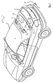
- a generally designated 1 Cabriolet vehicle is illustrated in a perspective view, wherein the closed folding top 2 has a built-in roof skin 3 rear window 4.
- the roof skin 3 is placed in its rear region below the rear window 4 on a top compartment lid 8 (FIG. 2) which is located in a plane with a boot lid 5.
- top compartment lid 8 With this substantially U-shaped in the rear-side body contour extending top compartment lid 8 is provided for receiving the top 2 top compartment 6 is closed on the top side.
- the folding-top compartment lid 8 is pivotably supported on the vehicle body by means of respective mirror-inverted hinge devices 7 (FIG. 2, only one hinge device) which are mirror-inverted relative to the vehicle longitudinal center plane M. Starting from this hinge device 7 in the direction of travel F forwards, the top compartment lid 8 cooperates with at least one closing device 10 provided in the region of an edge-side top clamping bracket 9 (in FIG. 1: dashed line in area III).
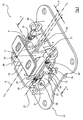
- the closing device 10 in the region of the top tensioning bow 9 or the top compartment lid 8 is illustrated in more detail according to a sectional view II-II.
- a on the top clamp bracket 9 befindliches link 11 is fixed to a counter member 13 which is provided below a through-opening 12 on the top compartment lid 8.
- a flap 14 (FIG. 6) not shown in detail in FIG. 2 is provided which can be moved out of the closed position by means of the connecting member 11 and actuates a switching element 15 (FIG. 3).
- the locking device 10 has, according to the invention as a connecting member 11, two abutment legs 16 and 17, which are held as L-shaped parts on an intermediate plate 19 (FIG. 3) fixed to the top clamping bracket 9.
- the two Investment limbs 16 and 17 are arranged at a distance S substantially mirror-inverted to the central longitudinal plane B of the locking device 10.
- the contact legs 16 and 17 form a receiving gap A, in which the counter-member 13 is at least partially positively received when closing the folding top 2.
- This connection position in the region of the closing device 10 is illustrated in particular in the perspective views according to FIGS. 3 and 4.
- connection unit With this connection unit is achieved that with the voltage applied to the respective counter member 13 abutment legs 16 and 17 transversely and / or longitudinally to the central longitudinal plane B movements, such as vibrations during movement of the vehicle, are absorbed by the largely play-free adjacent parts.
- the two abutment legs 16 and 17 have substantially the same length and thus form on the respective side surfaces of the counter-member 13 abutments that fix the top clamp bracket 9 transverse force stable.
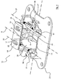
- the abutment limbs 16 and 17 are connected by at least one transverse web (not shown) running in the direction of the transverse axis R (FIG. 2), wherein this abutment can be introduced into a receiving recess 20 in the region of the counter element 13.
- the connecting member 11 and the two bearing legs 16 and 17 are held securely in the closed position of the top even when acting in the direction of the vehicle longitudinal center plane M loads.
- FIGS. 3 and 4 illustrate that the abutment legs 16 and 17 are provided at their respective free end with a laterally engageable on the counter-member 13 support lug 21 and 22 respectively.
- the non-illustrated transverse web in the region of the axis R is provided in the region of these two support lugs 21, 22 and the transverse web.
- the support lugs 21, 22 are each formed in the illustrated embodiment, roller-shaped, wherein the peripheral contour on the abutment legs 16, 17 each projecting frontally so that during the movement of the top clamping bracket 9, the roll-shaped support lugs 21, 22 pass through the through opening 12 (FIG. 5) on the top compartment lid 8 as protruding components and thereby gently on the flap 14 can be placed.
- FIGS. 3 to 5 show that the counter element 13 is supported on a support frame 23 which forms a central mold recess as a receiving opening and has a substantially rectangular contour (FIG. 4).
- the passage opening 12 is assigned to the region of the receiving opening of the support frame 23.
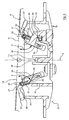
- the support frame 23 is provided in the region of its receiving opening with two flap parts forming the flap 14 25 and 26, the respective support axis 27, 28 parallel to the central longitudinal plane B of the locking device 10 extends. With these support axles 27 and 28, the flap parts 25 and 26 are held in a closed position opposite the upper edge region of the counter element 13 (FIG. 6) and can pivot out of this position into the open position by means of the attachment limbs 16, 17 located on the top clamping bar 9 (FIG. Fig. 3 to Fig. 5) are transferred.
- the two flap parts 25 and 26 are provided in the region of their in the closed position (Fig. 6) opposite peripheral contour, each with a mold recess 29, 29 ', in which the counter-member 13 is receivable so that the flap parts 25, 26 at their opening or Closing movement (Fig. 5, arrow E, E ') are freely displaced.
- the pivotable through the support legs 16 and 17 down flap parts 25, 26 are provided on its underside each with a support axis 27 and 28 comprehensive return spring 30, 31, so that the flap parts 25 and 26 in return movement to a contour plane K (Fig 5, dashed line) while closing the passage opening 12 almost completely.
- the flap parts 25 and 26 are adjusted so that an inclination of the contour plane K is detected visually appealing.
- the return springs 30, 31 are supported with their free legs 32 on a respective abutment plate 33 of the support frame 23 and the respective spring legs 32 'are attached to a contact part 35 of the flap part 25, 26.
- FIG. 5 illustrates that at least the flap part 25 is provided on the back with a sensing lever 34 which is electrically contactable placed in the open position pivoted flap parts 25 on the switching element 15 at a support area 36.
- a sensing lever 34 which is electrically contactable placed in the open position pivoted flap parts 25 on the switching element 15 at a support area 36.
- the two flap parts 25 and 26 are provided in the region of their two support axes 27 and 28 with a control assembly 37 which is adjustable by a screw 38 as a displaceable contact part so that the flap parts 25, 26 to the closing contour K of the top compartment cover 8 (FIG ) are optimally adaptable.
- a control assembly 37 which is adjustable by a screw 38 as a displaceable contact part so that the flap parts 25, 26 to the closing contour K of the top compartment cover 8 (FIG ) are optimally adaptable.
- the screw 38 In the closed position (not shown) is the screw 38 with its support surface 39, for example, on the abutment plate 33 so that the upwardly facing top surface of the flap portion 25, 26 is flush with the closing contour K.
- a bottom-side adjusting screw is also provided, with the support leg 16, 17 is defined an engagement depth limiting support position.
Landscapes
- Engineering & Computer Science (AREA)
- Mechanical Engineering (AREA)
- Lock And Its Accessories (AREA)
Claims (17)
- Véhicule cabriolet ayant une capote escamotable, en particulier une capote repliable (2), dont une bride de fixation de capote (9), en position fermée du toit, au moins en zone, laquelle peut être accrochée sur un couvercle de coffre à capote (8) situé à l'arrière, présente au moins un dispositif de fermeture (10) agencé entre celle-ci et le couvercle de coffre à capote (8), au niveau duquel un élément de liaison (11) se trouvant au niveau de la bride de fixation de capote (9) peut être fixé à un contre-élément (13) prévu au-dessous d'une ouverture de passage (12) au niveau du couvercle de coffre à capote (8), et grâce auquel il est prévu au moins un volet (14) dans la zone d'ouverture de passage (12) qui coopère avec un élément de commande (15) et peut être déplacé par l'intermédiaire de l'élément de liaison (11), caractérisé en ce que l'élément de liaison (11) présente au moins deux montants d'installation (16, 17) et, entre ceux-ci, une fente d'accueil (A) prenant au moins en partie le contre-élément (13) de façon à ce qu'il soit emboîté est formée.
- Véhicule cabriolet selon la revendication 1, caractérisé en ce que les montants d'installation (16, 17) du dispositif de fermeture (10) sont disposés de façon sensiblement parallèle au plan central longitudinal du véhicule (M) et espacés à la façon d'une image inversée par rapport au plan longitudinal central (B) du dispositif de fermeture (10) et de ce fait le contre-élément (13) passant dans le plan longitudinal central (B) s'engrène dans la fente d'accueil (A).
- Véhicule cabriolet selon la revendication 1 ou la revendication 2, caractérisé en ce que celui-ci est muni, dans la zone de liaison entre le couvercle de coffre à capote (8) et la bride de fixation de capote (9), de deux dispositifs de fermeture (10) essentiellement à la façon d'une image inversée à l'opposé du plan central longitudinal du véhicule (M).
- Véhicule cabriolet selon l'une des revendications 1 à 3, caractérisé en ce que , les montants d'installation (16, 17) étant adjacents au contre-élément (13), une liaison de support est formée, laquelle reçoit des mouvements opérationnels transversaux et/ou longitudinaux par rapport au plan central longitudinal du véhicule (M) provenant de la bride de fixation de capote (9) et/ou du couvercle de coffre à capote (8).
- Dispositif de fermeture selon l'une des revendications 1 à 4, caractérisé en ce que les deux montants d'installation (16, 17) peuvent chacun être disposés essentiellement avec une longueur égale au niveau du contre-élément (13).
- Dispositif de fermeture selon l'une des revendications 1 à 5, caractérisé en ce que les montants d'installation (16, 17) sont reliés par au moins une entretoise et celle-ci peut être insérée dans une cavité d'accueil (20) dans la zone du contre-élément (13).
- Dispositif de fermeture selon l'une des revendications 1 à 6, caractérisé en ce que les montants d'installation (16, 17) sont munis au niveau de chacune de leurs extrémités libres d'une saillie de support (21, 22) qui peut être disposée latéralement au niveau du contre-élément (13).
- Dispositif de fermeture selon la revendication 7, caractérisé en ce que les montants d'installation (16, 17) sont reliés par l'entretoise dans la zone des deux saillies de support (21, 22).
- Dispositif de fermeture selon l'une des revendications 1 à 8, caractérisé en ce que les montants d'installation (16, 17) présentent chacun des saillies de support (21, 22) formées en rouleaux, dont le contour périphérique fait saillie à l'avant des montants d'installation (16,17).
- Dispositif de fermeture selon l'une des revendications 1 à 9, caractérisé en ce que le contre-élément (13) est fourni au niveau d'un cadre porteur (23) formant un évidement central faisant office d'ouverture d'accueil et celui-ci est situé au-dessous de l'ouverture de passage (12) au niveau du couvercle de coffre à capote (8).
- Dispositif de fermeture selon la revendication 10, caractérisé en ce que le cadre porteur (23) qui présente le contre-élément (13) est muni dans la zone de son ouverture d'accueil de deux parties de volets (25, 26) qui forment le volet (14), dont chaque axe de support (26, 27) se prolonge parallèlement au plan longitudinal central (B) du dispositif de fermeture (10).
- Dispositif de fermeture selon la revendication 11, caractérisé en ce que les parties de volets (25, 26) sont maintenues dans une position fermée opposée au niveau de la zone de bord supérieure du contre-élément (13) et peuvent, par l'intermédiaire des montants d'installation (16, 17) situés au niveau de la bride de fixation de capote (9), être déplacées de façon pivotante vers le bas dans la position ouverte.
- Dispositif de fermeture selon l'une des revendications 11 et 12, caractérisé en ce que les deux parties de volets (25, 26) présentent chacune dans la zone de leur contour périphérique opposé en position fermée un évidement (29, 29') recevant en partie le contre-élément (13).
- Dispositif de fermeture selon l'une des revendications 11 à 13, caractérisé en ce que les deux parties de volets (25, 26) présentent chacune au niveau de leur côté inférieur un ressort de rappel (30, 31) qui enveloppe l'axe de support (26, 27), lequel est soutenu d'autre part au niveau du cadre porteur (23).
- Dispositif de fermeture selon l'une des revendications 11 à 14, caractérisé en ce qu'au moins une des parties de volets (26) est munie d'un levier palpeur (34) situé à l'arrière, lequel peut être disposé de façon à transmettre un contact (par le biais de 36) à l'élément de commande (15) électrique, lorsque les parties de volets (26) sont pivotées en position ouverte.
- Dispositif de fermeture selon la revendication 15, caractérisé en ce que les deux parties de volets (26, 27) présentent chacune un levier palpeur (34).
- Dispositif de fermeture selon l'une des revendications 11 à 16, caractérisé en ce que, au niveau des deux parties de volets (26, 27), un bloc de commande respectif (37) est prévu, avec lequel l'état de fermeture respectif du volet peut être ajusté grâce à une pièce d'équipement (38) déplaçable.
Applications Claiming Priority (3)
| Application Number | Priority Date | Filing Date | Title |
|---|---|---|---|
| DE10251409 | 2002-11-05 | ||
| DE10251409A DE10251409A1 (de) | 2002-11-05 | 2002-11-05 | Cabriolet-Fahrzeug mit versenkbarem Verdeck |
| PCT/DE2003/003609 WO2004041572A1 (fr) | 2002-11-05 | 2003-10-30 | Vehicule cabriolet comportant une capote escamotable |
Publications (2)
| Publication Number | Publication Date |
|---|---|
| EP1560726A1 EP1560726A1 (fr) | 2005-08-10 |
| EP1560726B1 true EP1560726B1 (fr) | 2006-08-02 |
Family
ID=32308474
Family Applications (1)
| Application Number | Title | Priority Date | Filing Date |
|---|---|---|---|
| EP03776823A Expired - Fee Related EP1560726B1 (fr) | 2002-11-05 | 2003-10-30 | Vehicule cabriolet comportant une capote escamotable |
Country Status (5)
| Country | Link |
|---|---|
| US (1) | US7425031B2 (fr) |
| EP (1) | EP1560726B1 (fr) |
| AU (1) | AU2003286112A1 (fr) |
| DE (2) | DE10251409A1 (fr) |
| WO (1) | WO2004041572A1 (fr) |
Families Citing this family (5)
| Publication number | Priority date | Publication date | Assignee | Title |
|---|---|---|---|---|
| DE102004052236A1 (de) * | 2004-10-27 | 2006-05-04 | Wilhelm Karmann Gmbh | Verriegelungseinrichtung für ein Cabrioletverdeck |
| FR2902372A1 (fr) * | 2006-06-14 | 2007-12-21 | Heuliez Sa | Vehicule a toit bloque a l'arriere et procede de commande de ce toit |
| DE102006042718B4 (de) * | 2006-09-12 | 2009-09-03 | Webasto Ag | Fahrzeug mit einem Faltdach |
| JP5245610B2 (ja) * | 2008-07-28 | 2013-07-24 | アイシン精機株式会社 | パネル移動装置 |
| US7819459B2 (en) * | 2009-02-11 | 2010-10-26 | Valmet Automotive Oy | Convertible vehicle |
Family Cites Families (7)
| Publication number | Priority date | Publication date | Assignee | Title |
|---|---|---|---|---|
| DE4120474C1 (fr) | 1991-06-21 | 1992-10-22 | Mercedes-Benz Aktiengesellschaft, 7000 Stuttgart, De | |
| DE4123516C1 (fr) * | 1991-07-16 | 1992-07-09 | Mercedes-Benz Aktiengesellschaft, 7000 Stuttgart, De | |
| DE9311798U1 (de) * | 1993-08-07 | 1994-12-08 | Karmann Gmbh W | Versenkbares Faltverdeck für ein Cabriolet-Fahrzeug |
| DE19650402C2 (de) * | 1996-12-05 | 2002-02-07 | Porsche Ag | Verdeckkastendeckel für ein Kraftfahrzeug |
| DE19935732A1 (de) | 1999-07-29 | 2001-02-08 | Daimler Chrysler Ag | System zum Spannen des flexiblen Materials eines versenkbaren Faltverdecks |
| US6227604B1 (en) * | 1999-11-01 | 2001-05-08 | Rkr Manufacturing, Inc. | Auto top conversion frame assembly |
| FR2834953B1 (fr) * | 2002-01-21 | 2004-06-04 | France Design | Dispositif de commande d'une tablette arriere de vehicule automobile |
-
2002
- 2002-11-05 DE DE10251409A patent/DE10251409A1/de not_active Withdrawn
-
2003
- 2003-10-30 WO PCT/DE2003/003609 patent/WO2004041572A1/fr not_active Application Discontinuation
- 2003-10-30 US US10/533,786 patent/US7425031B2/en not_active Expired - Fee Related
- 2003-10-30 AU AU2003286112A patent/AU2003286112A1/en not_active Abandoned
- 2003-10-30 DE DE50304506T patent/DE50304506D1/de not_active Expired - Lifetime
- 2003-10-30 EP EP03776823A patent/EP1560726B1/fr not_active Expired - Fee Related
Also Published As
| Publication number | Publication date |
|---|---|
| DE10251409A1 (de) | 2004-06-09 |
| US7425031B2 (en) | 2008-09-16 |
| AU2003286112A1 (en) | 2004-06-07 |
| DE50304506D1 (de) | 2006-09-14 |
| EP1560726A1 (fr) | 2005-08-10 |
| US20060197355A1 (en) | 2006-09-07 |
| WO2004041572A1 (fr) | 2004-05-21 |
Similar Documents
| Publication | Publication Date | Title |
|---|---|---|
| EP1184218B1 (fr) | Fenêtre arrière escamotable, en particulier verre solide pour un toit pliant pour véhicule motorisé | |
| EP0502295B1 (fr) | Toit convertible pour véhicule | |
| DE19533802C1 (de) | Verdeck für ein Fahrzeug, insbesondere Carbriolet | |
| DE19525587C1 (de) | Verdeckkastendeckel für ein in einem heckseitigen Verdeckkasten aufnehmbares Verdeck | |
| EP0494366A2 (fr) | Toit de véhicule | |
| DE19755254A1 (de) | Kraftfahrzeug mit einer versenkbaren Dachkonstruktion | |
| EP0749859A1 (fr) | Capote pliante pour véhicule convertible | |
| DE3415361A1 (de) | Windabweiseranordnung fuer ein kraftfahrzeugdach | |
| EP0760301A1 (fr) | Capote pliante pour cabriolet | |
| DE10252987B4 (de) | Cabriolet-Fahrzeug mit versenkbarem Verdeck | |
| EP1403116B1 (fr) | Véhicule convertible avec toit pliant rétractable | |
| DE3831790A1 (de) | Sitz, insbesondere kraftfahrzeugsitz | |
| EP0713794A1 (fr) | Capote pliante pour véhicule, en particulier pour voiture automobile | |
| EP1560726B1 (fr) | Vehicule cabriolet comportant une capote escamotable | |
| EP0806312B1 (fr) | Capote pliante pour véhicule convertible | |
| EP0763444B1 (fr) | Siège arrière pour véhicules automobiles, en particulier pour voitures | |
| EP0283577A2 (fr) | Toit décapotable pour voitures particulières | |
| EP0863033A2 (fr) | Dispositif de verrouillage pour capote de voiture convertible | |
| DE19723818C2 (de) | Kraftfahrzeug, insbesondere Personenkraftwagen | |
| DE3939144A1 (de) | Klappverdeck fuer fahrzeuge | |
| EP1254800B1 (fr) | Ensemble de toit pour vehicule | |
| DE4307158C1 (de) | Klappverdeck für Fahrzeuge | |
| DE3136592A1 (de) | Schmutzabweiser fuer kraftfahrzeuge | |
| DE10318076A1 (de) | Unfallschutzsystem für Fahrzeuge mit offenem Aufbau | |
| WO2006058703A1 (fr) | Dispositif coupe-vent pour un vehicule a carrosserie ouverte |
Legal Events
| Date | Code | Title | Description |
|---|---|---|---|
| PUAI | Public reference made under article 153(3) epc to a published international application that has entered the european phase |
Free format text: ORIGINAL CODE: 0009012 |
|
| 17P | Request for examination filed |
Effective date: 20050606 |
|
| AK | Designated contracting states |
Kind code of ref document: A1 Designated state(s): AT BE BG CH CY CZ DE DK EE ES FI FR GB GR HU IE IT LI LU MC NL PT RO SE SI SK TR |
|
| RBV | Designated contracting states (corrected) |
Designated state(s): DE FR GB IT |
|
| GRAP | Despatch of communication of intention to grant a patent |
Free format text: ORIGINAL CODE: EPIDOSNIGR1 |
|
| GRAS | Grant fee paid |
Free format text: ORIGINAL CODE: EPIDOSNIGR3 |
|
| GRAA | (expected) grant |
Free format text: ORIGINAL CODE: 0009210 |
|
| AK | Designated contracting states |
Kind code of ref document: B1 Designated state(s): DE FR GB IT |
|
| PG25 | Lapsed in a contracting state [announced via postgrant information from national office to epo] |
Ref country code: IT Free format text: LAPSE BECAUSE OF FAILURE TO SUBMIT A TRANSLATION OF THE DESCRIPTION OR TO PAY THE FEE WITHIN THE PRESCRIBED TIME-LIMIT;WARNING: LAPSES OF ITALIAN PATENTS WITH EFFECTIVE DATE BEFORE 2007 MAY HAVE OCCURRED AT ANY TIME BEFORE 2007. THE CORRECT EFFECTIVE DATE MAY BE DIFFERENT FROM THE ONE RECORDED. Effective date: 20060802 |
|
| REG | Reference to a national code |
Ref country code: GB Ref legal event code: FG4D Free format text: NOT ENGLISH |
|
| REF | Corresponds to: |
Ref document number: 50304506 Country of ref document: DE Date of ref document: 20060914 Kind code of ref document: P |
|
| GBT | Gb: translation of ep patent filed (gb section 77(6)(a)/1977) |
Effective date: 20061031 |
|
| ET | Fr: translation filed | ||
| PLBE | No opposition filed within time limit |
Free format text: ORIGINAL CODE: 0009261 |
|
| STAA | Information on the status of an ep patent application or granted ep patent |
Free format text: STATUS: NO OPPOSITION FILED WITHIN TIME LIMIT |
|
| 26N | No opposition filed |
Effective date: 20070503 |
|
| PGFP | Annual fee paid to national office [announced via postgrant information from national office to epo] |
Ref country code: IT Payment date: 20101022 Year of fee payment: 8 |
|
| PG25 | Lapsed in a contracting state [announced via postgrant information from national office to epo] |
Ref country code: IT Free format text: LAPSE BECAUSE OF NON-PAYMENT OF DUE FEES Effective date: 20111030 |
|
| REG | Reference to a national code |
Ref country code: GB Ref legal event code: 732E Free format text: REGISTERED BETWEEN 20131114 AND 20131120 |
|
| REG | Reference to a national code |
Ref country code: FR Ref legal event code: TP Owner name: VALMET AUTOMOTIVE OY, FI Effective date: 20131209 |
|
| REG | Reference to a national code |
Ref country code: DE Ref legal event code: R082 Ref document number: 50304506 Country of ref document: DE Representative=s name: KRONTHALER, SCHMIDT & COLL. PATENTANWALTSKANZL, DE Effective date: 20131128 Ref country code: DE Ref legal event code: R081 Ref document number: 50304506 Country of ref document: DE Owner name: VALMET AUTOMOTIVE OY, FI Free format text: FORMER OWNER: WILHELM KARMANN GMBH, 49084 OSNABRUECK, DE Effective date: 20131128 |
|
| REG | Reference to a national code |
Ref country code: FR Ref legal event code: PLFP Year of fee payment: 13 |
|
| REG | Reference to a national code |
Ref country code: FR Ref legal event code: PLFP Year of fee payment: 14 |
|
| PGFP | Annual fee paid to national office [announced via postgrant information from national office to epo] |
Ref country code: FR Payment date: 20161025 Year of fee payment: 14 Ref country code: GB Payment date: 20161025 Year of fee payment: 14 |
|
| GBPC | Gb: european patent ceased through non-payment of renewal fee |
Effective date: 20171030 |
|
| REG | Reference to a national code |
Ref country code: FR Ref legal event code: ST Effective date: 20180629 |
|
| PG25 | Lapsed in a contracting state [announced via postgrant information from national office to epo] |
Ref country code: GB Free format text: LAPSE BECAUSE OF NON-PAYMENT OF DUE FEES Effective date: 20171030 |
|
| PG25 | Lapsed in a contracting state [announced via postgrant information from national office to epo] |
Ref country code: FR Free format text: LAPSE BECAUSE OF NON-PAYMENT OF DUE FEES Effective date: 20171031 |
|
| PGFP | Annual fee paid to national office [announced via postgrant information from national office to epo] |
Ref country code: DE Payment date: 20211122 Year of fee payment: 19 |
|
| REG | Reference to a national code |
Ref country code: DE Ref legal event code: R119 Ref document number: 50304506 Country of ref document: DE |
|
| PG25 | Lapsed in a contracting state [announced via postgrant information from national office to epo] |
Ref country code: DE Free format text: LAPSE BECAUSE OF NON-PAYMENT OF DUE FEES Effective date: 20230503 |