EP1560479A2 - Cabinet having heat radiation function and heat radiation member - Google Patents

Cabinet having heat radiation function and heat radiation member Download PDF

Info

Publication number
EP1560479A2
EP1560479A2 EP04253152A EP04253152A EP1560479A2 EP 1560479 A2 EP1560479 A2 EP 1560479A2 EP 04253152 A EP04253152 A EP 04253152A EP 04253152 A EP04253152 A EP 04253152A EP 1560479 A2 EP1560479 A2 EP 1560479A2
Authority
EP
European Patent Office
Prior art keywords
heat
cabinet
transfer member
heat transfer
exterior
Prior art date
Legal status (The legal status is an assumption and is not a legal conclusion. Google has not performed a legal analysis and makes no representation as to the accuracy of the status listed.)
Granted
Application number
EP04253152A
Other languages
German (de)
French (fr)
Other versions
EP1560479B1 (en
EP1560479A3 (en
Inventor
Kazuo Fujitsu Limited Hirafuji
Hideki Fujitsu Limited Sonobe
Yoshihisa Fujitsu Limited Nakagawa
Current Assignee (The listed assignees may be inaccurate. Google has not performed a legal analysis and makes no representation or warranty as to the accuracy of the list.)
Fujitsu Ltd
Original Assignee
Fujitsu Ltd
Priority date (The priority date is an assumption and is not a legal conclusion. Google has not performed a legal analysis and makes no representation as to the accuracy of the date listed.)
Filing date
Publication date
Application filed by Fujitsu Ltd filed Critical Fujitsu Ltd
Priority to EP07123033A priority Critical patent/EP1916886B1/en
Publication of EP1560479A2 publication Critical patent/EP1560479A2/en
Publication of EP1560479A3 publication Critical patent/EP1560479A3/en
Application granted granted Critical
Publication of EP1560479B1 publication Critical patent/EP1560479B1/en
Anticipated expiration legal-status Critical
Expired - Lifetime legal-status Critical Current

Links

Images

Classifications

    • HELECTRICITY
    • H05ELECTRIC TECHNIQUES NOT OTHERWISE PROVIDED FOR
    • H05KPRINTED CIRCUITS; CASINGS OR CONSTRUCTIONAL DETAILS OF ELECTRIC APPARATUS; MANUFACTURE OF ASSEMBLAGES OF ELECTRICAL COMPONENTS
    • H05K7/00Constructional details common to different types of electric apparatus
    • H05K7/20Modifications to facilitate cooling, ventilating, or heating
    • H05K7/2039Modifications to facilitate cooling, ventilating, or heating characterised by the heat transfer by conduction from the heat generating element to a dissipating body
    • H05K7/20436Inner thermal coupling elements in heat dissipating housings, e.g. protrusions or depressions integrally formed in the housing
    • H05K7/20445Inner thermal coupling elements in heat dissipating housings, e.g. protrusions or depressions integrally formed in the housing the coupling element being an additional piece, e.g. thermal standoff
    • HELECTRICITY
    • H05ELECTRIC TECHNIQUES NOT OTHERWISE PROVIDED FOR
    • H05KPRINTED CIRCUITS; CASINGS OR CONSTRUCTIONAL DETAILS OF ELECTRIC APPARATUS; MANUFACTURE OF ASSEMBLAGES OF ELECTRICAL COMPONENTS
    • H05K7/00Constructional details common to different types of electric apparatus
    • H05K7/20Modifications to facilitate cooling, ventilating, or heating
    • H05K7/2029Modifications to facilitate cooling, ventilating, or heating using a liquid coolant with phase change in electronic enclosures
    • H05K7/20336Heat pipes, e.g. wicks or capillary pumps

Definitions

  • this embodiment employs the flat heat pipes 13-1, 13-2 having a flat external shape for the purpose of suppressing, to an allowably small level, increase and deviation in thermal resistance of side walls and so on of the cabinet 10 having the slits 12S-1, 12S-2.
  • the shape of such heat pipes is settable freely if the decrease in heat radiation efficiency due to the increase and deviation of the thermal resistance is allowable.

Landscapes

  • Engineering & Computer Science (AREA)
  • Microelectronics & Electronic Packaging (AREA)
  • Physics & Mathematics (AREA)
  • Thermal Sciences (AREA)
  • Cooling Or The Like Of Electrical Apparatus (AREA)

Abstract

The present invention relates to a heat radiation member (12) and a cabinet (10) to be installed outdoors in a hermetic state, having a heat radiation function for heat radiation of devices contained therein. The present invention facilitates maintenance and downsizing of the cabinet (10), and prevents the occurrence of noise. It includes: a cabinet body containing a heat source (16-1, 16-2); a cover member attached to an aperture (10F-A) of the cabinet (10) and having a guide portion (125-1, 12S-2) guiding, to an exterior of the cabinet (10), a heat transfer member (13-1, 13-2, 17) for transferring therethrough heat from the heat source (16-1, 16-2) by use of a hydraulic fluid; and a heat radiation part (12) being a thermal conductor and in contact with the heat transfer member (13-1, 13-2, 17) on a face and covering the heat transfer member (13-1, 13-2, 17) from the exterior of the cabinet (10) and having a heat radiation member (12SF, 14) on a face opposite to the face in contact with the heat transfer member (13-1, 13-2, 17).

Description

This application is based upon and claims the benefit of priority from Japanese Patent Application No. 2004-021522, filed on January 29, 2004, the entire contents of which are incorporated herein by reference.
The present invention relates to a cabinet installed outdoors in a hermetic state and realizing heat radiation of devices contained therein, and to a heat radiation member.
Recent years have seen a rapid increase in the number of portable type terminals accessing a mobile communication system, so that a radio base station apparatus forming a wireless zone in such a mobile communication system has been demanded for downsizing as well as increasing transmission power.
The downsizing and the increasing of the transmission power are technically contradictory demands, however, in case of installing the radio base station apparatus in a residential area, severe demands for reduction of noises imposes great restrictions on thermal design and mounting of the radio base station apparatus.
For a previously-proposed technique for heat radiation realizing both of the downsizing of, and increasing of the transmission power of, the radio base station apparatus, for example, promotion of heat radiation according to a forced air cooling using a heat pipe is disclosed in the following References 1 to 3.
  • [Reference 1] Japanese Unexamined Patent Application Publication No. Hei 6-235591 (Abstract)
  • [Reference 2] Japanese Unexamined Patent Application Publication No. Hei 7-83582 (Abstract)
  • [Reference 3] Japanese Unexamined Patent Application Publication No. Hei 7-113588 (Abstract)
  • The disclosure in all of the abovementioned documents, however, entails high costs and does not always achieve sufficiently high total reliability because fans used for forced air cooling generate a lot of noise and need to be exchanged for maintenance. Here, it is not necessary to exchange the fans if the heat radiation is sufficient by a natural air cooling.
    However, the natural air cooling is good for radiation of heat of small quantity, and it works only when a radiator has a sufficiently large heat radiation area. Besides, the increase in the heat radiation area leads to prevention of the downsizing of the radio base station apparatus, so that in reality, it is difficult to apply the natural air cooling to the radio base station apparatus whose essential portions are contained inside a hermetic cabinet so as not to be weather-beaten outdoors.
    Accordingly, it is desirable to provide a cabinet having a heat radiation function and a heat radiation member that are downsized and can improve serviceability and prevent occurrence of noise without imposing great restrictions on their shapes and structures.
    It is also desirable to maintain, at low cost, without noises, prescribed operation temperature of an apparatus or a system which is operable in diversified environments, and to expand the system or apparatus with increases in the power consumption without impairing the downsizing thereof.
    Furthermore, it is also desirable to stably and efficiently radiate heat generated inside a cabinet by a natural air cooling and by a heat transfer member with no coating thereon which prevents the heat radiation.
    It is also desirable to freely dispose a heat source inside a cabinet and freely decide with low cost the shape, size, and arrangement of a mechanism provided in a cover member and guiding a heat transfer member.
    It is desirable to efficiently radiate, by the natural air cooling, heat other than the heat transmitted to a heat transfer member from a heat source inside a cabinet.
    It is also desirable to efficiently radiate heat by the aforesaid natural air cooling even with a component thermally coupled to a heat transfer member disposed near the tip of an incoming radiation fin.
    It is desirable to also stably radiate heat generated inside the cabinet by the natural air cooling even when the cabinet includes a cover member for insulating a transfer member from both or one of the interior and exterior of the cabinet and for securing a heat radiation route from the heat transfer member to the exterior but this cover member does not directly function as a radiation fin.
    A cabinet according to an embodiment of the present invention includes a cabinet body containing a heat source. A cover member is attached to an aperture of the cabinet and includes a guide portion that guides, to an exterior of the cabinet, a heat transfer member transferring therethrough heat from the heat source by use of a hydraulic fluid. This embodiment also contains a heat radiation part that is a thermal conductor and in contact with the heat transfer member on a face, and covers the heat transfer member from the exterior of the cabinet and has a heat radiation member on a face opposite to the face in contact with the heat transfer member.
    In such a cabinet having a heat radiation function according to the above-described embodiment of the present invention, the heat is transmitted to the heat transfer member from the heat source inside the cabinet and radiated to the exterior of the cabinet via the heat transfer member. Further, the heat not transmitted to the heat transfer member and remaining inside the cabinet is radiated to the exterior from the aforesaid heat radiation member as a thermal conductor. In addition, the heat radiation member insulates the heat transfer member from the exterior of the cabinet. Consequently, it is possible to stably and efficiently radiate the heat generated inside the cabinet by the natural air cooling since the heat transfer member has no coating thereon which prevents the heat radiation.
    A cabinet according to a second embodiment of the present invention includes a cabinet body containing a heat source. A cover member is attached to an aperture of the cabinet and includes a guide portion that guides, to an exterior of the cabinet, a heat transfer member transferring therethrough heat from the heat source by use of a hydraulic fluid. This embodiment also contains a first heat radiation member having heat conductivity and has ventilation holes between a portion of the heat transfer member protruding to the exterior of the cabinet and the cover member. A heat radiation part is also contained, this part being a thermal conductor and in contact with the heat transfer member, and it covers a portion of the heat transfer member protruding from the cover member to the exterior of the cabinet so as not to cover more than one ventilation hole of the heat radiation member, and has a heat radiation member on a face opposite to the face in contact with said heat transfer member.
    In such a cabinet having a heat radiation function according to the second embodiment of the present invention, the heat is transmitted to the heat transfer member from the heat source inside the cabinet and radiated to the exterior via the heat transfer member, aforesaid heat radiation member, and ventilation holes. Further, the heat not transmitted to the heat transfer member and remaining inside the cabinet is radiated to the exterior via the ventilation holes from the aforesaid thermally conductive heat radiation member. In addition, this heat radiation member insulates the heat transfer member from the exterior of the cabinet. Consequently, it is possible to stably and efficiently radiate the heat generated inside the cabinet by the natural air cooling since the heat transfer member has no coating thereon which prevents the heat radiation.
    A cabinet according to a third embodiment of the present invention includes a cabinet body containing a heat source. A cover member is attached to an aperture of the cabinet and includes: a guide portion that guides, to an exterior of the cabinet, a heat transfer member transferring therethrough heat from the heat source by use of a hydraulic fluid; and a curved face with a predetermined curvature on a portion facing an interior of the cabinet when attached to the aperture so as to be in a contactable position with the heat transfer member inserted in the guide portion.
    Therefore, in the assembly process of the cabinet having a heat radiation function according to the third embodiment of the present invention, it is not necessary to machine the heat transfer member to bend in advance since it can bend in a direction of the position of the heat source inside the cabinet without any excessive deterioration in its property. Accordingly, it is possible to freely dispose a heat source inside a cabinet and freely decide with low cost the shape, size, and arrangement of a mechanism provided in a cover member and guiding a heat transfer member.
    A cabinet according to a fourth embodiment of the present invention has a cover member including an incoming radiation member on a portion that faces an interior of the cabinet when attached to the aperture of the cabinet. Thus, heat radiated or circulated by convection inside the cabinet is collected concentratedly by the incoming radiation member and radiated to the exterior via the cover member and the heat radiation member. This makes it possible to also radiate, by the natural air cooling, heat other than the heat transmitted to the heat transfer member from the heat source inside the cabinet with efficiency.
    A cabinet according to a fifth embodiment of the present invention includes a cabinet body containing a heat source. A cover member is attached to an aperture of the cabinet and includes: a guide portion that guides, to an exterior of the cabinet, a heat transfer member transferring therethrough heat from the heat source by use of a hydraulic fluid; a curved face with a predetermined curvature that connects with the guide portion; and an incoming radiation fin that has a height equal to a height of a portion of the curved face protruding most to the interior of the cabinet.
    That is, the heat transfer member is guided to the vicinity of a tip of the incoming radiation fin by the guide portion. Consequently, heat radiation is achievable by the aforesaid natural air cooling even with a component thermally coupled to the heat transfer member disposed near the tip of the incoming radiation fin.
    A heat radiation member according to a sixth embodiment of the present invention is formed as a thermal conductor used for closing an aperture of a cabinet containing a heat source. The heat source is thermally coupled to a heat transfer member transferring therethrough heat by use of a hydraulic fluid. The heat radiation member includes a hole or a groove guiding the heat transfer member to an exterior of the aperture from an interior thereof. That is, such a heat radiation member corresponds to the aforesaid cover member. Accordingly, it is able to stably radiate heat generated inside the cabinet by the natural air cooling even when the cabinet includes a cover member for insulating a transfer member from both or one of the interior and exterior of the cabinet and for securing a heat radiation route from the heat transfer member to the exterior but this cover member does not directly function as a radiation fin.
    Reference will now be made, by way of example, to the accompanying drawings, in which:
  • Fig. 1 is a perspective view of an embodiment of the present invention;
  • Fig. 2 is a cross sectional view of the embodiment of the present invention;
  • Fig. 3 is an assembly view (1) of the embodiment of the present invention;
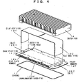
  • Fig. 4 is an assembly view (2) of the embodiment of the present invention; and
  • Fig. 5 shows an example of a backlash.
  • Hereinafter, an embodiment of the present invention will be described in detail with reference to the drawings. Fig. 1 is a perspective view of an embodiment of the present invention. Fig. 2 is a cross sectional view of the embodiment of the present invention. Fig. 3 is an assembly view (1) of the embodiment of the present invention. Fig. 4 is an assembly view (2) of the embodiment of the present invention. Hereinafter, the configuration of the embodiment of the present invention will be described with reference to Fig. 1 to Fig. 4.
    A cabinet 10 contains elements (hereinafter referred to simply as a circuit) of a radio base station apparatus other than elements disposed outdoors such as an antenna. As shown in Fig. 1, the cabinet 10 is composed of an inner frame 10F with a rectangular cross section corresponding to a top portion, side portions, and a bottom portion of the cabinet 10, a base fin 10B screw-fixed to one aperture of the inner frame 10F, and a cover 10C screw-fixed to the other aperture of the inner frame 10F. The inner frame 10F has a rectangular aperture 10F-A on the top portion, and connectors and terminals used for connecting the following items to the aforesaid circuit attached to the bottom portion:
  • 1) A feeder laid to a feeding point of an antenna (not shown);
  • 2) A communication link used for exchange of information with a base station controlling station;
  • 3) A power supply line used for supplying driving power from an exterior;
  • 4) A cable for connection to equipment applied to maintenance and operation; and
  • 5) A ground line for being grounded on the earth.
  • Note that waterproof packing rings are fitted into marginal parts of a pair of opposing apertures of the inner frame 10F so as to watertightly connect the aforesaid inner frame 1 OF and the base fin 10B, and the inner frame 10F and the cover 10C. The inner frame 10F has a groove 10F-T in a peripheral area of the aforesaid aperture 10F-A on the top portion, and the groove has an O-ring 11 serving as a waterproof packing fitted thereto, a base plate fin 12 is screw-fixed to the inner frame 10F to sandwich the O-ring 11 therebetween.
    The base plate fin 12 is formed of the following elements as shown in Fig. 2:
  • 1) A plate member 12P having substantially rectangular slits 12S-1, 12S-2 with a predetermined curvature at positions adjacent to inner sides of two short sides of the aperture 10F-A of the inner frame 10F, respectively;
  • 2) An incoming radiation fin 12IRF formed of a plurality of projections that protrudes at a regular pitch in an area of a bottom face of the plate member 12P, the area being surrounded by the aperture 10F-A of the inner frame 10F;
  • 3) Bending jigs 12BG-1, 12BG-2 having curved faces that smoothly continue from faces with longer sides of faces forming the aforesaid slits 12S-1, 12S-2 in the area surrounded by the aperture 10F-A of the inner frame 10F, the height of top portions of the bending jigs 12BG-1, 12BG-2 from the bottom face of the plate member 12 being equal to that of top portions of the incoming radiation fin 12IRF; and
  • 4) A supplementary outer fin 12SF constituted of an array of projections and a flat plate member 12L, the projections provided at a regular pitch in parallel to the longer sides of the slits 12S-1 , 12S-2 in an area sandwiched by the slits 12S-1 , 12S-2of an upper face of the plate member 12P, the plate member 12L being bridged on top portions of the array of these projections.
  • One of the ends of flat heat pipes 13-1, 13-2 are inserted in the slits 12S-1, 12S-2 respectively, and then the other ends thereof are both bent as shown in Fig. 2 to Fig. 4 to be in contact with an upper face of the supplementary outer fin 12S-F (the plate member 12L) with substantially the same length. The other end of the flat heat pipe 13-2 passes through the slit 12S-2 and is bent along the curved face of the bending jig 12BG-2 to substantially keep in contact with the top portions of the incoming radiation fin 12IRF with a desired length.
    An outer fin 14 having a groove on a bottom face thereof is screw-fixed to the upper face of the plate member 12P. The groove has a shape and a size to satisfy the following conditions:
  • 1) The outer fin 14 and the supplementary outer fin 12SF (the plate member 12L) are stably thermally coupled to the flat heat pipes 13-1, 13-2 without causing any deterioration in characteristics of the flat heat pipes 13-1, 13-2;
  • 2) A ventilation path is formed between the supplementary outer fin 12SF and the exterior; and
  • 3) The flat heat pipes 13-1, 13-2 are insulated from the exterior by the outer fin 14 and the plate member 12L so as to seal the flat heat pipes 13-1, 13-2.
  • In a hollow portion of the cabinet 10 provided are a printed board 1 5-1 disposed in parallel to the longer sides of an aperture of the slit 12-S1 and a printed board 15-2 disposed perpendicularly to the longer sides of an aperture of the slit 12S-2. A heating element 16-1 such as an LSl (Large Scale Integration) mounted on the printed board 15-1 is thermally coupled to one end of the flat heat pipe 13-1. Further, a heating element 16-2 mounted on the printed board 15-2 is thermally coupled to one end of a flat heat pipe 17, and the other end of the flat heat pipe 17 is in contact with the other end of the flat heat pipe 13-2 that is shaped in advance as described above.
    Note that the constituent elements of this embodiment excluding the O-ring 11, the printed boards 15-1, 15-2, and the heating elements 16-1, 16-2 are preferably formed of a metal material such as an aluminum material to have the same heat conductivity.
    The operation of this embodiment is as follows.
    Heat is generated by the heating element 16-1 (16-2) inside the cabinet10. The flat heat pipe 13-1 (17, 13-2) closely thermally coupled to the heating element 16-1 (16-2) guides most of the heat to the outer fin 14 and the supplementary outer fin 12SF for radiation of the heat to the exterior. Here, the flat heat pipes 13-1, 13-2 are sandwiched by the outer fin 14 and the base plate fin 12 and at least upper and lower faces of bent portions "n" in Fig. 3 are in surface contact with the outer fin 14 and the base plate fin 12, respectively.
    Further, the following routes are for radiation of some of the heat generated inside the cabinet 10 to the exterior which is not transmitted to the aforesaid flat heat pipe 13-1 (17, 1 3-2) but circulates by convection or is radiated.
  • 1) A route via outer wall faces of the base fin 10B and the cover 10C and side portions and a bottom portion of wall faces of the inner frame 10F.
  • 2) A route via the incoming radiation fin 12IRF and the outer fin 14.
  • 3) A route via the incoming radiation fin 12IRF, the flat heat pipes 13-1, 13-2, and the outer fin 14 (or the supplementary outer fin 12SF).
  • Inside the cabinet 10, the flat heat pipes 13-1, 13-2, 17 are insulated from the exterior by the inner frame 10F, the base fin 10B, the cover 10C, and the base plate fin 12. Further, in an area sandwiched by the outer fin 14 and the base plate fin 12, the flat heat pipes 13-1, 13-2 are insulated from the exterior by the bottom portion of the outer fin 14 and the base plate fin 12 (the plate member 12L).
    Therefore, if the heating element 16-1 (16-2) is the source of major heat generated inside the cabinet 10, it is possible to radiate the heat to the exterior quickly and efficiently via the flat heat pipe 13-1 (17, 13-2), the outer fin 14, and the supplementary outer fin 12SF which are closely thermally coupled to the heating element 16-1. Moreover, the insulation of the flat heat pipes 13-1, 13-2, 17 from the exterior makes it is possible to prevent deterioration in their characteristics and faults that would be caused if they were weather-beaten as well as deterioration in heat radiation characteristics that would be caused if the flat heat pipes 13-1, 13-2, 17 had corrosion-resistant coating thereon.
    As described above, this embodiment can realize natural air cooling of heat generated inside the cabinet 10 with reliability and stability without extremely increasing in the area of wall faces of the cabinet 10. Consequently, the system and apparatus to which an embodiment of the present invention is applied is able to provide high-level output without occurrence of noises which deteriorates surrounding conditions and with the downsizing and cost reduction thereof achieved.
    Note that in this embodiment the incoming radiation fin 12IRF is constructed of a set of plural projections disposed in the aperture 10F-A around which warmed air inside the inner frame 10F (the cabinet 10) may be mostly distributed. However, such an incoming radiation fin 12IRF may be formed at any positions on the inner walls of the cabinet 10 (including inner walls of the inner frame 10F, the base fin 10B, and the cover 10C) if heat radiation is realized with a desired degree according to the natural air cooling.
    Moreover, in this embodiment the outer fin 14 has the pitch of 8 mm to 10 mm to be suitable for the characteristics of fluid air in the exterior and desirable for efficient natural air cooling. However, the physical shape, size and arrangement of such an outer fin 14 are settable freely as long as natural air cooling is achieved with desired efficiency.
    Further, in this embodiment, the pitch of the incoming radiation fin 12IRF is set to be far smaller than the pitch of the outer fin 14 in order to secure a large heat receiving area inside the cabinet 10. However, the physical shape, size, and arrangement of such an incoming radiation fin 12IRF are settable freely as long as natural air cooling is achieved with desired efficiency.
    Moreover, this embodiment employs the flat heat pipes 13-1, 13-2 having a flat external shape for the purpose of suppressing, to an allowably small level, increase and deviation in thermal resistance of side walls and so on of the cabinet 10 having the slits 12S-1, 12S-2. However, the shape of such heat pipes is settable freely if the decrease in heat radiation efficiency due to the increase and deviation of the thermal resistance is allowable.
    Further, in this embodiment, thermal coupling between the flat heat pipes 17, 13-2 is maintained at a high degree by using, for example as shown in Fig. 5, a backlash of the heat pipe 1 3-2 that occurs due to an elasticity specific to the heat pipe 13-2 by bending the heat pipe 13-2 along the bending jig 12BG-2. A restoring force of an elastic tip portion of the flat heat pipe 17 acts between the flat heat pipes 13-2, 17, so that the flat heat pipe 17 pushes up the heat pipe 13-2 until the incoming radiation fin 12IRF presses down the heat pipe 13-2, as shown in detail as "a cross section vertical to the paper" in Fig. 2. However, if the flat heat pipe 13-1 is not bent along the bending jig 12BG-1, and is thermally coupled to the flat heat pipe 1 7, for example, the heat pipes 13-1, 17 may be fixed to each other with a fixing metal or the like to keep the thermal coupling therebetween.
    Furthermore, the heating element 16-2 is thermally coupled to the flat heat pipe 1 7 closely thermally coupled to the flat heat pipe 13-2. However, the heating element 16-2 may be directly thermally coupled to the tip of the flat heat pipe 13-2 by gradually twisting the flat heat pipe 13-2 in a longitudinal direction thereof, for example.
    Moreover, this embodiment is provided with the supplementary outer fin 12SF in addition to the outer fin 14. However, an embodiment of the present invention is not limited to such a configuration, and both or one of the outer fin 14 and the supplementary outer fin 12SF are unnecessary if heat radiation is achieved with desired efficiency by the natural air cooling.
    Further, in this embodiment, portions of the flat heat pipes 13-1, 13-2 are guided from the interior of the cabinet 10 through the slits 12S-1, 12S-2 and insulated from the exterior by the outer fin 14 and the plate member 12L (the supplementary outer fin 12SF). Outside air passes through the ventilation path formed between the outer fin 14 and the supplementary outer fin 12SF, thereby radiating heat efficiently by the outer fin 14.
    However, the flat heat pipes 13-1, 13-2 may be insulated from the exterior by either of the following elements:
  • 1) A cover member such as a rack, a shelf, or the like that is thermally coupled to a member substituting the outer fin 14 and that replaces the groove formed in the bottom portion of the outer fin 14; and
  • 2) A cover member or an outer fin that is in close contact with the plate member 1 2P in place of the plate member 12L to cover the flat heat pipes 13-1, 13-2, in case that the supplementary outer fin 12SF is not providable.
  • Furthermore, in this embodiment, the shape and size of the bending jigs 12BG-1, 12BG-2 and a curvature of slopes formed on side faces of the bending jigs 12BG-1, 12BG-2 may be arbitrarily decided if (a) they adapt to the position of the heating element thermally coupled to the tip of the heat pipe bent along the slope as well as to the shapes, sizes, and materials of this heat pipe and of a route inside the heat pipe through which a hydraulic fluid moves, and the characteristics of the hydraulic fluid; (b) desired thermal resistance and thermal conductivity are obtainable; and (c) in the assembling process the heat pipe can be bent with high accuracy at low cost. Therefore, it is not necessary that the bending jigs 1 2BG-1, 12BG-2 have a height equal to that of the top portions of the incoming radiation fin 12IRF.
    Further, in this embodiment, the bending jigs 12BG-1, 12BG-2 may be formed, for example, as a single projection (or an array of a plurality of projections) also serving as the incoming radiation fin 12IRF, or as a notch (or an array of notches) formed in the incoming radiation fin 12IRF in view of improving heat receiving efficiency of the incoming radiation fin 12IRF.
    Moreover, in this embodiment, the width of the flat heat pipes 13-1, 13-2 is not greatly different from that of the outer fin 14 and the supplementary outer fin 12SR, so that the flat heat pipes 13-1, 13-2 are thermally coupled to most of areas of the outer fin 14 and the supplementary outer fin 12SR with substantial uniformity. However, an embodiment of the present invention is not limited to such a configuration. For example, heat pipes with nonflat cross sectional shapes are applicable, or when the width of the applied heat pipes greatly differs from that of the outer fin 14 and the supplementary outer fin 12SR, these heat pipes may be laid such that temperature distributions of the outer fin 14 and the supplementary outer fin 12SR are to be uniform with a desired degree.
    Further, the essential portion of this embodiment is structured of the outer fin 14 and the base plate fin 12 which is combined with the outer fin 14 to insulate the flat heat pipes 13-1, 13-2 from the exterior, realizing the aforesaid natural air cooling. However, such an essential portion may have any of the following structure, for example:
  • 1) A set of members that are assembled and joined together by a building block system according to the maximum quantity of heat to be radiated;
  • 2) A set of small members constituting respective portions and made of existing materials or materials of a standard size and shape through combining or jointing with each other irrespective of the aforesaid heat quantity;
  • 3) A set of different members exchangeable depending on a desired heat quantity and standardized in terms of the assembly mechanism;
  • 4) A single member integrated with a heat pipe or a valve or the like used for confining a hydraulic fluid in view of reduction in the number of man-hours taken for the assembly by reducing the number of components or in view of yield improvement;
  • 5) A single member being a part of a heat pipe or being a route for transferring hydraulic fluid, and connectable to another heat pipe.
  • Further, in this embodiment, most of the heat generated in the heating elements 16-1, 16-2 is transmitted to the area sandwiched by the base plate fin 12 and the outer fin 14 via the heat pipes and is radiated to the exterior via the outer fin 14 and the supplementary outer fin 12SF. However, an embodiment of the present invention is not limited to such a configuration. All or part of the flat heat pipes 13-1, 13-2, 17 may be replaced by, for example, a heat transfer element such as a thermosiphon or the like that transfers heat therethrough efficiently by a circulative heat medium (hydraulic fluid).

    Claims (6)

    1. A cabinet (10) having a heat radiation function, comprising:
      a cabinet body containing a heat source (16-1, 16-2);
      a cover member (10C) attached to an aperture (10F-A) of said cabinet (10), and including a guide portion (12S-1, 12S-2) that guides a heat transfer member (13-1, 13-2, 17) to an exterior of said cabinet (10), the heat transfer member (13-1, 13-2, 17) transferring therethrough heat from said heat source (16-1, 16-2) by use of a hydraulic fluid; and
      a heat radiation part (12) being a thermal conductor and in contact with said heat transfer member (13-1, 13-2, 17) on a face, and covering said heat transfer member (13-1, 13-2, 17) from the exterior of said cabinet and having a heat radiation member (12SF, 14) on a face opposite to the face in contact with said heat transfer member (13-1, 13-2, 17).
    2. A cabinet (10) having a heat radiation function, comprising:
      a cabinet body containing a heat source (16-1, 16-2);
      a cover member (10C) attached to an aperture (1 0F-A) of said cabinet (10), and including a guide portion (12S-1, 12S-2) that guides a heat transfer member (13-1, 13-2, 17) to an exterior of said cabinet (10), the heat transfer member (13-1, 13-2, 17) transferring therethrough heat from said heat source (16-1, 16-2) by use of a hydraulic fluid;
      a first heat radiation member with heat conductivity, having ventilation holes between a portion of said heat transfer member (13-1, 13-2, 1 7) and said cover member (1 0C), the portion protruding to the exterior of said cabinet (10); and
      a heat radiation part (12) being a thermal conductor and in contact with said heat transfer member (13-1, 13-2, 17) on a face, and covering a portion of said heat transfer member (13-1, 13-2, 17) so as not to cover more than one ventilation hole of said first heat radiation member and having a second heat radiation member (14) on a face opposite to the face in contact with said heat transfer member (13-1, 13-2, 17), the portion protruding from said cover member (1 0C) to the exterior of said cabinet (10).
    3. A cabinet (10) having a heat radiation function, comprising:
      a cabinet body containing a heat source (16-1, 16-2); and
      a cover member (10C) attached to an aperture (1 OF-A) of said cabinet (10), and including a guide portion (12S-1, 12S-2) that guides a heat transfer member (13-1, 13-2, 1 7) to an exterior of said cabinet (10), and a curved face of a predetermined curvature on a portion facing an interior of said cabinet (10) when attached to the aperture (10F-A) so as to be in a contactable position with said heat transfer member (13-1, 13-2, 17) inserted in said guide portion (12S-1, 12S-2) , the heat transfer member (13-1, 13-2, 17) transferring therethrough heat from said heat source (16-1, 16-2) by use of a hydraulic fluid.
    4. The cabinet (10) according to any preceding claim, wherein
         said cabinet body further includes an incoming radiation member (12 IRF) on a portion that faces an interior of said cabinet (10) when attached to the aperture (1 0F-A).
    5. A cabinet (10) having a heat radiation function, comprising:
      a cabinet body containing a heat source (16-1, 16-2); and
      a cover member (10C) attached to an aperture (10F-A) of said cabinet (10), and including a guide portion (12S-1, 125-2) that guides a heat transfer member (13-1, 13-2, 1 7) to an exterior of said cabinet (10), a curved face of a predetermined curvature connecting with said guide portion (12S-1, 12S-2) , and an incoming radiation fin (12 IRF) having a height equal to a height of a portion of said curved face protruding most to an interior of said cabinet (10), the heat transfer member (13-1, 13-2, 17) transferring therethrough heat from said heat source (16-1, 16-2) by use of a hydraulic fluid.
    6. A heat radiation member (12) being a thermal conductor used for closing an aperture (10F-A) of a cabinet (10) which contains a heat source (16-1, 16-2) which is thermally coupled to a heat transfer member (13-1, 13-2, 17) for transferring therethrough heat by use of a hydraulic fluid, the heat radiation member (12) comprising a hole or a groove (12S-1, 12S-2) guiding said heat transfer member (13-1, 13-2, 17) from an interior of said cabinet (10) to an exterior of said aperture (10F-A).
    EP04253152A 2004-01-29 2004-05-27 Cabinet having heat radiation function and heat radiation member Expired - Lifetime EP1560479B1 (en)

    Priority Applications (1)

    Application Number Priority Date Filing Date Title
    EP07123033A EP1916886B1 (en) 2004-01-29 2004-05-27 Cabinet having heat radiation function and heat radiation member

    Applications Claiming Priority (2)

    Application Number Priority Date Filing Date Title
    JP2004021522A JP4408224B2 (en) 2004-01-29 2004-01-29 Housing with heat dissipation function
    JP2004021522 2004-01-29

    Related Child Applications (1)

    Application Number Title Priority Date Filing Date
    EP07123033A Division EP1916886B1 (en) 2004-01-29 2004-05-27 Cabinet having heat radiation function and heat radiation member

    Publications (3)

    Publication Number Publication Date
    EP1560479A2 true EP1560479A2 (en) 2005-08-03
    EP1560479A3 EP1560479A3 (en) 2006-06-21
    EP1560479B1 EP1560479B1 (en) 2008-12-03

    Family

    ID=34650821

    Family Applications (2)

    Application Number Title Priority Date Filing Date
    EP07123033A Expired - Lifetime EP1916886B1 (en) 2004-01-29 2004-05-27 Cabinet having heat radiation function and heat radiation member
    EP04253152A Expired - Lifetime EP1560479B1 (en) 2004-01-29 2004-05-27 Cabinet having heat radiation function and heat radiation member

    Family Applications Before (1)

    Application Number Title Priority Date Filing Date
    EP07123033A Expired - Lifetime EP1916886B1 (en) 2004-01-29 2004-05-27 Cabinet having heat radiation function and heat radiation member

    Country Status (4)

    Country Link
    US (1) US7130193B2 (en)
    EP (2) EP1916886B1 (en)
    JP (1) JP4408224B2 (en)
    DE (2) DE602004022727D1 (en)

    Cited By (2)

    * Cited by examiner, † Cited by third party
    Publication number Priority date Publication date Assignee Title
    WO2008066764A1 (en) * 2006-11-22 2008-06-05 Tyco Electronics Corporation Heat dissipation system for photovoltaic array interconnection sytem
    CN112566441A (en) * 2019-09-25 2021-03-26 中车株洲电力机车研究所有限公司 Heat pipe radiator and IGBT converter heat radiation device

    Families Citing this family (73)

    * Cited by examiner, † Cited by third party
    Publication number Priority date Publication date Assignee Title
    EP1538760A1 (en) * 2003-06-12 2005-06-08 Matsushita Electric Industrial Co., Ltd. Base station device
    US7190577B2 (en) * 2004-09-28 2007-03-13 Apple Computer, Inc. Cooling system with integrated passive and active components
    FR2876812B1 (en) * 2004-10-15 2006-12-22 J C C Chereau Aeronautique COOLING FLUID DEVICE FOR COMPUTER
    US7277282B2 (en) * 2004-12-27 2007-10-02 Intel Corporation Integrated circuit cooling system including heat pipes and external heat sink
    US7345877B2 (en) * 2005-01-06 2008-03-18 The Boeing Company Cooling apparatus, system, and associated method
    DE102005014534A1 (en) * 2005-03-30 2006-10-05 Hush Technologies Investments Ltd. Housing for a computer
    KR100683412B1 (en) * 2005-06-11 2007-02-20 삼성전자주식회사 computer
    CN101072482A (en) * 2006-05-12 2007-11-14 富准精密工业(深圳)有限公司 Radiating device and radiating system using same
    TWI306188B (en) * 2006-08-01 2009-02-11 Compal Electronics Inc Waterproof thermal management module and portable electronic apparatus using the same
    US20080087406A1 (en) * 2006-10-13 2008-04-17 The Boeing Company Cooling system and associated method for planar pulsating heat pipe
    CN101193534A (en) * 2006-11-29 2008-06-04 富准精密工业(深圳)有限公司 Heat radiator
    FR2910779A1 (en) * 2006-12-21 2008-06-27 Thales Sa Electronic equipment casing i.e. electronic rack, for aircraft, has heat collectors inserted between hot spots and inner thermal radiators, and heat conductors connecting outer thermal radiator with collectors through front wall of casing
    US7606030B2 (en) * 2007-12-12 2009-10-20 Fu Zhun Precision Industry (Shen Zhen) Co., Ltd. Heat dissipation device
    US8254850B2 (en) * 2008-06-11 2012-08-28 Adc Telecommunications, Inc. Communication module component assemblies
    US8549741B2 (en) * 2008-06-11 2013-10-08 Adc Telecommunications, Inc. Suspension method for compliant thermal contact of electronics modules
    US8031470B2 (en) * 2008-06-11 2011-10-04 Adc Telecommunications, Inc. Systems and methods for thermal management
    TW201012370A (en) * 2008-09-05 2010-03-16 Pegatron Corp Electronic apparatus
    BRPI0918292A2 (en) * 2008-09-08 2015-12-22 Intergraph Technologies Co rugged computer capable of operating in high temperature environments
    JP4658174B2 (en) * 2008-09-24 2011-03-23 株式会社日立製作所 Electronic equipment
    US8612582B2 (en) 2008-12-19 2013-12-17 Openpeak Inc. Managed services portals and method of operation of same
    US20100159898A1 (en) * 2008-12-19 2010-06-24 Openpeak, Inc. Services platform for networked devices that provide telephony and digital media services
    US8856322B2 (en) 2008-12-19 2014-10-07 Openpeak Inc. Supervisory portal systems and methods of operation of same
    US8650290B2 (en) 2008-12-19 2014-02-11 Openpeak Inc. Portable computing device and method of operation of same
    US8615581B2 (en) 2008-12-19 2013-12-24 Openpeak Inc. System for managing devices and method of operation of same
    US8745213B2 (en) 2008-12-19 2014-06-03 Openpeak Inc. Managed services platform and method of operation of same
    US8788655B2 (en) 2008-12-19 2014-07-22 Openpeak Inc. Systems for accepting and approving applications and methods of operation of same
    US8713173B2 (en) 2008-12-19 2014-04-29 Openpeak Inc. System and method for ensuring compliance with organizational policies
    KR100934124B1 (en) * 2008-12-26 2009-12-29 에이스트로닉스 주식회사 Dustproof and vibration resistant industrial computer
    TWM366286U (en) * 2009-02-13 2009-10-01 Asia Vital Components Co Ltd Heat dissipation structure of communication case
    TWM371400U (en) * 2009-02-13 2009-12-21 Asia Vital Components Co Ltd Heat-dissipation device of communication box
    JP2010231730A (en) * 2009-03-30 2010-10-14 Suzuki Gokin Kk High temperature alarm indicator
    US8208259B1 (en) * 2009-05-08 2012-06-26 Augmentix Corporation System, apparatus and method for cooling electronic components
    US7924565B2 (en) * 2009-05-12 2011-04-12 Asia Vital Components Co., Ltd. Heat dissipation structure for communication chassis
    US8081463B2 (en) * 2009-06-16 2011-12-20 Asia Vital Components Co., Ltd. Water-cooled communication chassis
    US20110100606A1 (en) * 2009-11-02 2011-05-05 Beijing AVC Technology Research Center Co., Ltd. Heat dissipating cavity
    US20110100607A1 (en) * 2009-11-02 2011-05-05 Beijing AVC Technology Research Center Co., Ltd. Heat dissipating cavity of looped heat pipe
    TW201116983A (en) * 2009-11-06 2011-05-16 Nat Univ Tsing Hua Heat dissipation structure of electronic apparatus
    US9077796B2 (en) 2010-08-17 2015-07-07 Openpeak Inc. System containing a mobile communication device and associated docking station
    GB201016047D0 (en) * 2010-09-24 2010-11-10 Pace Plc Means for heating dissipation for electrical and/or electronic apparatus
    US8650658B2 (en) 2010-10-25 2014-02-11 Openpeak Inc. Creating distinct user spaces through user identifiers
    FR2969379B1 (en) * 2010-12-17 2013-02-15 Thales Sa COOLING AN ELECTRONIC EQUIPMENT
    US8488312B2 (en) 2011-02-14 2013-07-16 Adc Telecommunications, Inc. Systems and methods for thermal management for telecommunications enclosures using heat pipes
    US20140083652A1 (en) * 2011-05-24 2014-03-27 Nec Corporation Sealed casing
    TWM426756U (en) * 2011-08-04 2012-04-11 Cooler Master Co Ltd Heat sink with the heat pipe protection mechanism
    US9014023B2 (en) 2011-09-15 2015-04-21 International Business Machines Corporation Mobile network services in a mobile data network
    US8695060B2 (en) 2011-10-10 2014-04-08 Openpeak Inc. System and method for creating secure applications
    US9681317B2 (en) * 2011-11-16 2017-06-13 International Business Machines Corporation Mitigating effects of predicted failures in a mobile network basestation due to weather
    KR101360730B1 (en) * 2011-12-02 2014-02-07 엘지이노텍 주식회사 Cooling device and electronic device thereof
    CN103249275A (en) * 2012-02-07 2013-08-14 鸿富锦精密工业(深圳)有限公司 Heat dissipation system
    US11006548B2 (en) * 2013-02-01 2021-05-11 Smart Embedded Computing, Inc. Method and device to provide uniform cooling in rugged environments
    US9310139B2 (en) * 2013-03-15 2016-04-12 Qualcomm Incorporated Vapor chambers based skin material for smartphones and mobile devices
    JP2015207586A (en) * 2014-04-17 2015-11-19 富士通株式会社 Heat radiator, electronic apparatus, and base station device
    US9578781B2 (en) * 2014-05-09 2017-02-21 Advanced Cooling Technologies, Inc. Heat management for electronic enclosures
    US9232013B1 (en) 2014-09-05 2016-01-05 Openpeak Inc. Method and system for enabling data usage accounting
    US20160071040A1 (en) 2014-09-05 2016-03-10 Openpeak Inc. Method and system for enabling data usage accounting through a relay
    US8938547B1 (en) 2014-09-05 2015-01-20 Openpeak Inc. Method and system for data usage accounting in a computing device
    US9100390B1 (en) 2014-09-05 2015-08-04 Openpeak Inc. Method and system for enrolling and authenticating computing devices for data usage accounting
    US9350818B2 (en) 2014-09-05 2016-05-24 Openpeak Inc. Method and system for enabling data usage accounting for unreliable transport communication
    US10220725B2 (en) * 2015-05-13 2019-03-05 Ge Global Sourcing Llc System and method for passively cooling an enclosure
    US10383261B2 (en) * 2015-10-20 2019-08-13 Ge Global Sourcing Llc Heat transfer chassis and method for forming the same
    US10356948B2 (en) 2015-12-31 2019-07-16 DISH Technologies L.L.C. Self-adjustable heat spreader system for set-top box assemblies
    US10080067B2 (en) * 2015-12-31 2018-09-18 Infinera Corporation Heat relay network system for telecommunication equipment
    JP2017127914A (en) * 2016-01-19 2017-07-27 セイコーエプソン株式会社 Robot and robot system
    CN106163242B (en) * 2016-08-31 2019-05-28 杭州华为数字技术有限公司 A cabinet heat exchange system and server
    CN106785218A (en) * 2017-01-19 2017-05-31 清华大学深圳研究生院 Thermal management structure and unmanned aerial vehicle using the thermal management structure
    US10721840B2 (en) 2017-10-11 2020-07-21 DISH Technologies L.L.C. Heat spreader assembly
    JP2020053570A (en) * 2018-09-27 2020-04-02 Necプラットフォームズ株式会社 Heat dissipation structure
    US10874036B2 (en) * 2018-10-08 2020-12-22 Delta Electronics, Inc. Cabinet and electronic device
    TWI735074B (en) * 2019-11-06 2021-08-01 新加坡商鴻運科股份有限公司 Lts heat sink and electronic device having the same
    CN113727082B (en) * 2021-08-20 2023-12-01 深圳亮仔光电科技有限公司 Initiative intelligent heat abstractor and projector sealing ray apparatus
    US11800687B2 (en) 2021-08-26 2023-10-24 Dish Network L.L.C. Heat transfer assembly
    CN115548886B (en) * 2022-09-28 2024-03-08 江苏泽宇电力设计有限公司 Auxiliary detection type small-resistance grounding resistance cabinet
    CN118138524B (en) * 2024-05-06 2024-08-02 江苏泽宇智能电力股份有限公司 Router board card with automatic alarm function

    Family Cites Families (12)

    * Cited by examiner, † Cited by third party
    Publication number Priority date Publication date Assignee Title
    US4306613A (en) * 1980-03-10 1981-12-22 Christopher Nicholas S Passive cooling system
    JPS59169159A (en) 1983-03-16 1984-09-25 Mitsubishi Electric Corp Semiconductor device
    US4600050A (en) * 1985-04-26 1986-07-15 Noren Don W Heat exchanger
    JPH06235591A (en) 1993-02-08 1994-08-23 Fanuc Ltd Cooling device for closed casing
    JP3364764B2 (en) 1993-09-13 2003-01-08 アクトロニクス株式会社 Sealed equipment housing cooling device
    JPH07113588A (en) 1993-10-15 1995-05-02 Furukawa Electric Co Ltd:The Heat pipe type cooler
    US6104611A (en) * 1995-10-05 2000-08-15 Nortel Networks Corporation Packaging system for thermally controlling the temperature of electronic equipment
    CA2199239A1 (en) * 1997-03-05 1998-09-05 Trevor Zapach Electronic unit
    EP0946085A1 (en) * 1998-03-24 1999-09-29 Lucent Technologies Inc. Electronic apparatus having an environmentally sealed external enclosure
    AU2001281624A1 (en) 2000-08-22 2002-03-04 Hb Innovation Ltd. Distributed thermal management system for electronic components
    JP2004021522A (en) 2002-06-14 2004-01-22 Sony Corp Information processing apparatus and method, and program
    JP3757200B2 (en) * 2002-09-25 2006-03-22 株式会社日立製作所 Electronic equipment with cooling mechanism

    Cited By (2)

    * Cited by examiner, † Cited by third party
    Publication number Priority date Publication date Assignee Title
    WO2008066764A1 (en) * 2006-11-22 2008-06-05 Tyco Electronics Corporation Heat dissipation system for photovoltaic array interconnection sytem
    CN112566441A (en) * 2019-09-25 2021-03-26 中车株洲电力机车研究所有限公司 Heat pipe radiator and IGBT converter heat radiation device

    Also Published As

    Publication number Publication date
    JP4408224B2 (en) 2010-02-03
    EP1560479B1 (en) 2008-12-03
    EP1560479A3 (en) 2006-06-21
    DE602004018097D1 (en) 2009-01-15
    DE602004022727D1 (en) 2009-10-01
    EP1916886B1 (en) 2009-08-19
    US20050168951A1 (en) 2005-08-04
    EP1916886A2 (en) 2008-04-30
    EP1916886A3 (en) 2008-07-09
    JP2005214503A (en) 2005-08-11
    US7130193B2 (en) 2006-10-31

    Similar Documents

    Publication Publication Date Title
    US7130193B2 (en) Cabinet having heat radiation function and heat radiation member
    KR102131417B1 (en) Multi input and multi output antenna apparatus
    KR102233029B1 (en) Antenna apparatus
    JP4404726B2 (en) Automotive power converter
    US7663883B2 (en) Heat transfer mechanism, heat dissipation system, and communication apparatus
    EP1753073B1 (en) Compliant, internally cooled antenna apparatus and method
    US20150148111A1 (en) Closure apparatus of wireless communication device
    JP5995015B2 (en) Compound module
    US7110256B2 (en) Communication device
    US7039374B2 (en) Transmitting and amplifying unit for wireless communication device
    EP1122583B1 (en) Temperature stabiliser for liquid crystal displays (LCD)
    US7944711B2 (en) Discrete electronic component and related assembling method
    JP2004039857A (en) Antenna device
    JP3942849B2 (en) Array antenna cooling structure
    US20230120949A1 (en) Wireless communication module for medical fluid pump
    CN113423253A (en) Heat dissipation assembly and electronic equipment
    JP2001085880A (en) Electronics
    CN115642928A (en) Radio frequency transceiver, connection component for radio frequency transceiver, and radio frequency transceiver system
    CN219843534U (en) Compact frequency converter
    WO2023005417A1 (en) Heat dissipation assembly and electronic device
    CN215582422U (en) Heat dissipation assembly and electronic equipment
    CN222786108U (en) Circuit board and electric equipment thereof
    US20260005421A1 (en) Heat-dissipation device, heat-dissipation module and antenna apparatus including same
    CN223142364U (en) Heat dissipation device and communication equipment
    CN223942782U (en) FTTR-B gateway

    Legal Events

    Date Code Title Description
    PUAI Public reference made under article 153(3) epc to a published international application that has entered the european phase

    Free format text: ORIGINAL CODE: 0009012

    AK Designated contracting states

    Kind code of ref document: A2

    Designated state(s): AT BE BG CH CY CZ DE DK EE ES FI FR GB GR HU IE IT LI LU MC NL PL PT RO SE SI SK TR

    AX Request for extension of the european patent

    Extension state: AL HR LT LV MK

    PUAL Search report despatched

    Free format text: ORIGINAL CODE: 0009013

    AK Designated contracting states

    Kind code of ref document: A3

    Designated state(s): AT BE BG CH CY CZ DE DK EE ES FI FR GB GR HU IE IT LI LU MC NL PL PT RO SE SI SK TR

    AX Request for extension of the european patent

    Extension state: AL HR LT LV MK

    17P Request for examination filed

    Effective date: 20061016

    AKX Designation fees paid

    Designated state(s): DE FR GB

    17Q First examination report despatched

    Effective date: 20070821

    GRAP Despatch of communication of intention to grant a patent

    Free format text: ORIGINAL CODE: EPIDOSNIGR1

    GRAS Grant fee paid

    Free format text: ORIGINAL CODE: EPIDOSNIGR3

    GRAS Grant fee paid

    Free format text: ORIGINAL CODE: EPIDOSNIGR3

    GRAA (expected) grant

    Free format text: ORIGINAL CODE: 0009210

    AK Designated contracting states

    Kind code of ref document: B1

    Designated state(s): DE FR GB

    REG Reference to a national code

    Ref country code: GB

    Ref legal event code: FG4D

    REF Corresponds to:

    Ref document number: 602004018097

    Country of ref document: DE

    Date of ref document: 20090115

    Kind code of ref document: P

    PLBE No opposition filed within time limit

    Free format text: ORIGINAL CODE: 0009261

    STAA Information on the status of an ep patent application or granted ep patent

    Free format text: STATUS: NO OPPOSITION FILED WITHIN TIME LIMIT

    26N No opposition filed

    Effective date: 20090904

    REG Reference to a national code

    Ref country code: FR

    Ref legal event code: PLFP

    Year of fee payment: 13

    REG Reference to a national code

    Ref country code: FR

    Ref legal event code: PLFP

    Year of fee payment: 14

    REG Reference to a national code

    Ref country code: FR

    Ref legal event code: PLFP

    Year of fee payment: 15

    PGFP Annual fee paid to national office [announced via postgrant information from national office to epo]

    Ref country code: GB

    Payment date: 20180329

    Year of fee payment: 15

    PGFP Annual fee paid to national office [announced via postgrant information from national office to epo]

    Ref country code: DE

    Payment date: 20180515

    Year of fee payment: 15

    PGFP Annual fee paid to national office [announced via postgrant information from national office to epo]

    Ref country code: FR

    Payment date: 20180412

    Year of fee payment: 15

    REG Reference to a national code

    Ref country code: DE

    Ref legal event code: R119

    Ref document number: 602004018097

    Country of ref document: DE

    GBPC Gb: european patent ceased through non-payment of renewal fee

    Effective date: 20190527

    PG25 Lapsed in a contracting state [announced via postgrant information from national office to epo]

    Ref country code: DE

    Free format text: LAPSE BECAUSE OF NON-PAYMENT OF DUE FEES

    Effective date: 20191203

    Ref country code: GB

    Free format text: LAPSE BECAUSE OF NON-PAYMENT OF DUE FEES

    Effective date: 20190527

    PG25 Lapsed in a contracting state [announced via postgrant information from national office to epo]

    Ref country code: FR

    Free format text: LAPSE BECAUSE OF NON-PAYMENT OF DUE FEES

    Effective date: 20190531