EP1560433A2 - Procédé et appareil pour la commande d'un désentrelaceur à plusieurs champs avec provision d'un démarrage et d' arrêt visuellement agréable - Google Patents
Procédé et appareil pour la commande d'un désentrelaceur à plusieurs champs avec provision d'un démarrage et d' arrêt visuellement agréable Download PDFInfo
- Publication number
- EP1560433A2 EP1560433A2 EP05000716A EP05000716A EP1560433A2 EP 1560433 A2 EP1560433 A2 EP 1560433A2 EP 05000716 A EP05000716 A EP 05000716A EP 05000716 A EP05000716 A EP 05000716A EP 1560433 A2 EP1560433 A2 EP 1560433A2
- Authority
- EP
- European Patent Office
- Prior art keywords
- field
- video
- fields
- input
- size
- Prior art date
- Legal status (The legal status is an assumption and is not a legal conclusion. Google has not performed a legal analysis and makes no representation as to the accuracy of the status listed.)
- Withdrawn
Links
- 230000003044 adaptive effect Effects 0.000 title description 25
- 230000008859 change Effects 0.000 title description 13
- 238000000034 method Methods 0.000 claims abstract description 29
- 230000008569 process Effects 0.000 claims description 8
- 230000004044 response Effects 0.000 claims description 8
- 101000961071 Homo sapiens NF-kappa-B inhibitor alpha Proteins 0.000 description 20
- 102100039337 NF-kappa-B inhibitor alpha Human genes 0.000 description 20
- 230000000750 progressive effect Effects 0.000 description 14
- 238000010586 diagram Methods 0.000 description 12
- 230000002123 temporal effect Effects 0.000 description 7
- 239000000203 mixture Substances 0.000 description 5
- 230000002441 reversible effect Effects 0.000 description 5
- XRKZVXDFKCVICZ-IJLUTSLNSA-N SCB1 Chemical compound CC(C)CCCC[C@@H](O)[C@H]1[C@H](CO)COC1=O XRKZVXDFKCVICZ-IJLUTSLNSA-N 0.000 description 4
- 101100439280 Saccharomyces cerevisiae (strain ATCC 204508 / S288c) CLB1 gene Proteins 0.000 description 4
- 238000012545 processing Methods 0.000 description 4
- 238000012937 correction Methods 0.000 description 3
- 238000001514 detection method Methods 0.000 description 3
- 241000023320 Luma <angiosperm> Species 0.000 description 2
- 238000013459 approach Methods 0.000 description 2
- 230000008901 benefit Effects 0.000 description 2
- 230000002457 bidirectional effect Effects 0.000 description 2
- OSWPMRLSEDHDFF-UHFFFAOYSA-N methyl salicylate Chemical compound COC(=O)C1=CC=CC=C1O OSWPMRLSEDHDFF-UHFFFAOYSA-N 0.000 description 2
- 230000001360 synchronised effect Effects 0.000 description 2
- 230000007704 transition Effects 0.000 description 2
- 230000000007 visual effect Effects 0.000 description 2
- 230000005540 biological transmission Effects 0.000 description 1
- 238000004891 communication Methods 0.000 description 1
- 230000006854 communication Effects 0.000 description 1
- 239000002131 composite material Substances 0.000 description 1
- 230000006835 compression Effects 0.000 description 1
- 238000007906 compression Methods 0.000 description 1
- 230000006837 decompression Effects 0.000 description 1
- 238000011161 development Methods 0.000 description 1
- 238000001914 filtration Methods 0.000 description 1
- 230000006870 function Effects 0.000 description 1
- 239000000463 material Substances 0.000 description 1
- 230000000116 mitigating effect Effects 0.000 description 1
- 238000012986 modification Methods 0.000 description 1
- 230000004048 modification Effects 0.000 description 1
- 238000011160 research Methods 0.000 description 1
- 238000012552 review Methods 0.000 description 1
Images


Classifications
-
- H—ELECTRICITY
- H04—ELECTRIC COMMUNICATION TECHNIQUE
- H04N—PICTORIAL COMMUNICATION, e.g. TELEVISION
- H04N7/00—Television systems
- H04N7/01—Conversion of standards, e.g. involving analogue television standards or digital television standards processed at pixel level
- H04N7/0117—Conversion of standards, e.g. involving analogue television standards or digital television standards processed at pixel level involving conversion of the spatial resolution of the incoming video signal
- H04N7/012—Conversion between an interlaced and a progressive signal
-
- H—ELECTRICITY
- H04—ELECTRIC COMMUNICATION TECHNIQUE
- H04N—PICTORIAL COMMUNICATION, e.g. TELEVISION
- H04N7/00—Television systems
- H04N7/01—Conversion of standards, e.g. involving analogue television standards or digital television standards processed at pixel level
- H04N7/0135—Conversion of standards, e.g. involving analogue television standards or digital television standards processed at pixel level involving interpolation processes
- H04N7/0137—Conversion of standards, e.g. involving analogue television standards or digital television standards processed at pixel level involving interpolation processes dependent on presence/absence of motion, e.g. of motion zones
Definitions
- Deinterlacing takes interlaced video fields and coverts them into progressive frames, at double the display rate. Certain problems may arise concerning the motion of objects from image to image. Objects that are in motion are encoded differently in interlaced fields from progressive frames. Video images, encoded in deinterlaced format, containing little motion from one image to another may be deinterlaced into progressive format with virtually no problems or visual artifacts. However, problems arise with video images containing a lot of motion and change from one image to another, when converted from interlaced to progressive format. As a result, some video systems were designed with motion adaptive deinterlacers.
- broadcasted analog standard definition (SD) images are sampled at 720x480 frames in progressive systems or 720x240 fields in interlaced systems.
- analog signals coming in are always 720 wide.
- the broadcast still has the same format, with a width of 720 pixels per line.
- the method may comprise determining the size of an input field; determining the expected size of an output field; scaling the input field to the expected size; and outputting fields with the expected size.
- the method may further comprise outputting a black field of the expected size when no input field is received.
- the expected size of the outputted fields may be programmable in an embodiment of the present invention.
- the system may comprise an integrated filter that scales the incoming fields to produce output fields continuously with the expected size.
- the filter may be a poly-phase scaler.
- the filter may be a finite impulse response filter, or an infinite impulse response filter.
- the system may output a field with start of a field signal; end of a field signal; start of a line signal; and end of a line signal.
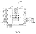
- Fig. 1a illustrates a block diagram of an exemplary architecture for positioning of a MAD-3:2, in accordance with an embodiment of the invention.
- Fig. 1b illustrates a block diagram of exemplary interfaces for the MAD-3:2 shown in Fig. 1a, in accordance with an embodiment of the invention.
- Fig. 1c illustrates a block diagram of an exemplary flow of the algorithm, which may be utilized by the MAD-3:2 of Fig. 1a and Fig. 1b, in accordance with an embodiment of the invention.
- Fig. 2 illustrates a top-level diagram of an exemplary motion adaptive deinterlacer, in accordance with an embodiment of the present invention.
- Fig. 3 illustrates an exemplary input and output of a deinterlacer, in accordance with an embodiment of the present invention.
- Fig. 4 illustrates a block diagram of an exemplary motion adaptive deinterlacer with interfaces, in accordance with an embodiment of the present invention.
- Fig. 5 illustrates a block diagram of an exemplary video network input control block, in accordance with an embodiment of the present invention.
- aspects of the present invention relate to processing video signals. More specifically, certain embodiments of the invention relate to a method and system that support a variety of video source sizes. Although the following discusses an embodiment of the invention with respect to video processing, it should be understood that the present invention may be modified for use in other systems. Additionally, while the following discusses aspects of the present invention with respect to horizontal scaling, it should be understood that the present invention may also be used for vertical scaling.
- Certain aspects of the invention may comprise methods and systems for a motion adaptive deinterlacer (MAD) capable of reverse 3:2 pull-down and 3:2 pull-down with cadence detection, which may be referred to as MAD-3:2 or MAD32, that may be utilized in a video network (VN).
- the algorithms and architectures for the motion adaptive deinterlacer may be adapted to acquire interlaced video fields from one of a plurality of video sources in the video network and convert the acquired interlaced video fields into progressive frames, at double the display rate, in a visually pleasing manner.
- the motion adaptive deinterlacer (MAD-3:2) may be adapted to accept interlaced video input from a video bus (VB) and output deinterlaced, progressive video to the video bus (BUS) utilized by the video network.
- the motion adaptive deinterlacer may accept, for example, 720x480i and produce, for example, 720x480p in the case of NTSC.
- the motion adaptive deinterlacer (MAD) may accept, for example, 720x576i and produce, for example, 720x576p.
- Horizontal resolution may be allowed to change on a field-by-field basis up to, for example, a width of 720.
- the motion adaptive algorithm utilized by the motion adaptive deinterlacer (MAD-3:2) may be adapted to smoothly blend various approximations for the missing pixels to prevent visible contours produced by changing decisions.
- a plurality of fields of video may be utilized to determine motion. For example, in an embodiment of the invention, five fields of video may be utilized to determine motion.
- the motion adaptive deinterlacer (MAD) may produce stable non-jittery video with reduced risk of visual artifacts due to motion being misinterpreted while also providing improved still frame performance.
- the motion adaptive deinterlacer (MAD-3:2) may also provide additional fields per field type of quantized motion information, which may be selectable in order to reduce the risk of misinterpretation. For example, up to three (3) additional fields or more, per field type, of quantized low-cost motion information may optionally be selected in order to reduce risk of misinterpreted motion even further. This may provide a total historical motion window of up to, for example, 10 fields in a cost effective manner.
- Integrated cross-chrominance removal functionality may be provided, which may aid in mitigating or eliminating NTSC comb artifacts.
- a directional compass filtering may also be provided in order to reduce or eliminate jaggies in moving diagonal edges.
- the MAD-3:2 may provide reverse 3:2 pull-down for improved quality from film-based sources.
- the algorithms and architectures for the motion adaptive deinterlacer may also be adapted to provide bad-edit detection in order to ensure a visually pleasing transition to new cadence in situations where editing may have been carelessly performed.
- per-pixel correction may also be provided to improve the quality of subject matter containing both film and video at the same time. For example, per-pixel correction may be utilized for interlaced titles, which have been overlaid on film-based content.
- the motion adaptive deinterlacer (MAD-3:2) may also provide optional CPU control over, for example, 3:2 and/or 2:2 cadence detection and correction.
- Fig. 1a is a block diagram of an exemplary architecture illustrating the positioning of a MAD-3:2 100, in accordance with an embodiment of the present invention.
- the MAD-3:2 100 along with a plurality of scalers (102, 104, 106, and 108), for example, may be positioned between a first crossbar 110 and a second crossbar 112.
- the first crossbar 110 may be referred to as an input crossbar and the second crossbar 112 may be referred to as an output crossbar.
- the MAD-3:2 100 may comprise at least one video network input and at least one video network output and may be configured to maintain its own additional field stores.
- a feedback path may be provided from the output of the second crossbar 112 to the input of the first crossbar 110.
- This may allow any of the standard definition (SD) video sources such as the MPEG feeders 103 and 105, video feeders 107, 109, 111, 113 and 115, and/or VDEC 117, and so on, to function as an input to the MAD32 100 and/or one of the scalers 102, 104, 106, and 108.
- the VDEC 117 may be an analog video decoder that may process NTSC signals to separate color from luma.
- the MPEG feeders 103 and 105 may accept 4:2:0 and 4:2:2 video data and supply 4:2:2 video data.
- the video feeders 107, 109, 111, 113 and 115 may accept 4:2:2 video data and supply 4:2:2 video data.
- the output of the second crossbar 112 may be passed back to the first crossbar 110 via the feedback path 114.
- United States Patent Application Serial No. 10/314,525 filed December 9, 2002 entitled “Network Environment for Video Processing Modules” discloses an exemplary crossbar network module and associated system, which is representative of the video network crossbar that may be utilized in connection with the present invention. Accordingly, United States Patent Application Serial No. 10/314,525 filed December 9, 2002 is hereby incorporated herein by reference in its entirety.
- Fig. 1b is a block diagram illustrating exemplary interfaces for the MAD-3:2 100 shown in Fig. 1a, in accordance with an embodiment of the present invention.
- the MAD-3:2 100 may comprise a plurality of bus interfaces and may include the capability to generate one or more system CPU interrupts.
- the MAD-3:2 100 may run on, for example, a single system clock. However, the invention may not be so limited and more than one clock may be utilized.
- the MAD-3:2 100 may include a video bus (VB) input 120, a video bus output 122, and, for example, two independent bidirectional read/write SCB client connections, SCB0 124 and SCB1 126.
- VB video bus
- the SCB may be an internal bus utilized to access frames/fields stored in the memory.
- the video bus (VB) input 120 may be utilized for supplying fields to the MAD-3:2 100.
- the video bus output 122 may allow the deinterlaced output frames to be transferred throughout the video network and pass through a scaler before reaching a composite or capture block.
- An RBUS interface 128 may be utilized to configure the MAD-3:2 100 or to access its status via one or more interface signals and/or registers.
- the RBUS may be a general-purpose bus utilized for programming registers for control and configuration of the CPU. At least a portion of the interfaces of the MAD-3:2 100 may be synchronous to a clock input of the scaler.
- a video network receiver input error interrupt 130 may be generated on an input field size, which may differ from a programmed field size, which is expected.
- An inverse telecine ready interrupt 132 may be generated for every field, or at least some fields, at the point in time when the statistics gathered in the previous field are ready to be read by a CPU or other processor.
- Fig. 1c is a block diagram illustrating an exemplary flow of the algorithm which may be utilized by the MAD-3:2 100 of Fig. 1a and Fig. 1b, in accordance with an embodiment of the present invention.
- a data flow corresponding to the algorithm utilized for deinterlacing the luma component of video.
- the algorithm may effectively be divided into two sub-blocks.
- diagrammed on the left of Fig. 1c is the motion adaptive deinterlacer (MAD) method of deinterlacing 150 and on the right, there is shown the reverse 3:2 pulldown method 180.
- MID motion adaptive deinterlacer
- reverse 3:2 pulldown method 180 For every output pixel, motion adaptive deinterlacing 150, reverse 3:2 pulldown 180, or a blend 160 of motion adaptive deinterlacing and reverse 3:2 deinterlacing may be utilized to determine a motion-adapted value of the output pixel under consideration.
- the motion adaptive deinterlacer (MAD) 150 may comprise a directional filter 154, a temporal average 156, and a blender 158.
- the MAD 150 may comprise suitable logic, code, and/or circuitry and may be adapted for performing the MAD method of deinterlacing.
- a processor may be adapted to perform the operation of the MAD 150.
- the MAD 150 may comprise local memory for storage of data and/or instructions.
- the directional filter 154 may comprise suitable logic, code, and/or circuitry and may be adapted for spatially approximating the value of the output pixel.
- the temporal average 156 may comprise suitable logic, code, and/or circuitry and may be adapted for temporal approximation of the value of the output pixel.
- the blender 158 may comprise suitable logic, code, and/or circuitry and may be adapted to combine the temporal and spatial approximations of the value of the output pixel.
- the MAD 150 may receive input field pixels from an interlaced video field and convert them into output frame fields in a progressive frame, at double the display rate.
- the horizontal resolution of the input to the MAD 150 may change on a field-by-field basis.
- the MAD 150 may utilize a motion adaptive algorithm that may smoothly blend various approximations for the output pixels to prevent visible contours, which may be produced by changing decisions. In an embodiment of the present invention, it may be necessary to determine the amount of motion around each output pixel, to use an appropriate approximation for the output pixel.
- the MAD 150 may utilize the directional filter 154, the temporal average 156, and the blender 158 to obtain a motion-adapted value for the output pixel that is visually pleasing.
- Fig. 2 illustrates a top-level diagram of an exemplary motion adaptive deinterlacer 255, in accordance with an embodiment of the present invention.
- the MAD 255 may be a component of a video network.
- a MAD 255 may take interlaced video fields from a video source and convert them into progressive frames, at double the display rate.
- the MAD 255 may accept interlaced video input 257 from a video bus, and output deinterlaced, progressive video 259 to the video bus.
- the horizontal resolution of the input to the MAD 255 may change on a field-by-field basis.
- the MAD 255 may utilize a motion adaptive algorithm that may smoothly blend various approximations for the missing pixels to prevent visible contours, which may be produced by changing decisions. In an embodiment of the present invention, it may be necessary to determine the amount of motion around each output pixel, to use an appropriate approximation for the output pixel.
- the MAD 255 may utilize a directional filter 261 for the spatial approximation, a temporal average block 263 for the temporal approximation, and a blend control with a blender 265 to combine both approximations.
- Fig. 3 illustrates an exemplary input and output of a deinterlacer, in accordance with an embodiment of the present invention.
- the first field 201 is a top field
- the second field 203 is a bottom field
- the third field 205 is a top field again.
- the first field 201 may be a bottom or top field, and the sequence of fields may alternate between top and bottom as appropriate depending on the first field 201.
- the deinterlacer may take the lines present in the field (black-colored lines in Fig. 3 ) and fill in the absent lines (clear lines in Fig. 3 ) to produce an output frame.
- the process of deinterlacing may be seen as taking in a line of pixels from the source field and producing two output lines of pixels.
- One line is the line that came from the source field and may be called the "present” line (black).
- the other line is the line that needs to be created and may be called the "absent" line (cross-hatched lines).
- This double output line pattern may then repeat to create the output frame.
- the pixels of the absent line may be computed using a deinterlacing procedure in accordance with an embodiment of the present invention.
- a line of present pixels may be output in parallel with a line of absent pixels.
- the two lines of output may make up the progressive frame lines.
- Fig. 4 illustrates a block diagram of an exemplary motion adaptive deinterlacer 301 with interfaces, in accordance with an embodiment of the present invention.
- the MAD 301 may have five bus interfaces and may produce two system interrupts.
- the MAD 301 may run on a single system clock 303.
- the MAD 301 may have a video bus input 305, a video bus output 307, and two bidirectional (read/write) SCB client connections, SCB0 client 309 and SCB1 client 311.
- the video bus input 305 may be used for supplying fields to the MAD 301.
- the video bus output 307 may allow the deinterlaced output frames to continue in the video network.
- the register bus (RBUS) interface 313 may be used to configure the MAD 301 or to access its status.
- the video network receiver input error interrupt 315 may be generated when an input field size differs from an expected field size that was programmed.
- the inverse telecine ready interrupt 317 may be exerted every field at a point in time when the statistics gathered in the previous field are ready to be read by the CPU.
- a picture may be sent to the MAD 301 one pixel at a time in raster order, through the video bus input 305.
- the MAD 301 may use the RBUS interface 313 to access internal registers.
- the MAD 301 may use the SCB0 client 309 to maintain a store of several previous interlaced fields.
- the SCB1 client 311 may or may not be active. When the SCB1 client 311 is active, it may maintain a store of two lots of three fields of quantized motion.
- Fig. 5 illustrates a block diagram of an exemplary video network input control block 401, in accordance with an embodiment of the present invention.
- the video network input control block 401 may be adapted to take the video network input 403 from the video bus and provide the video network feed 405 to other components of the system.
- the video network input control block 401 may horizontally scale the input video, depending on the horizontal size of the input video.
- the video network input control block 401 may also provide line alignment of pixels to the rest of the MAD system.
- the video network input control block 401 may halt at the end of a field and wait for a signal such as, for example, a new Field_Start_Strobe signal 407, which may indicate the start of a new field.
- the video network receiver 409 may ensure that the height of the field received on the video network input 403 is equal to Height_in_size 415, which may be the number of vertical lines expected.
- the video network receiver 409 may have a locally programmed expected line width such as, for example, 720 pixels per line.
- the video network receiver 409 may stop accepting from the video network input 403. New input from the video network input 403 may be accepted after receiving the Field_Start_Strobe signal 407.
- the video network receiver 409 may discard any additional lines received beyond the Height_in_size 415. If too few lines are received, i.e., less than Height_in_size 415, additional lines may be inserted consisting of black pixels.
- the horizontal poly-phase scaler 413 may be an 8-phase scaler with 8 taps per phase and may include phase interpolation to provide a total of 64 available phase positions.
- a parameter such as, for example, Width_in_size 411, which may be locally programmed, may indicate the expected number of pixels per line at the input of the horizontal poly-phase scaler 413. Additional pixels, over Width_in_size 411, may be discarded. Too few pixels, less than Width_in_size 411, may be made up to the required width by inserting black pixels.
- the horizontal poly-phase scaler 413 may pass frames at their current size or scale them up, based on the size of the input frame and the expected frame size.
- the horizontal poly-phase scaler 413 may also scale frames down. The resolution of the incoming fields may change from one field to another, and such a change may be indicated to horizontal poly-phase scaler 413.
- the horizontal poly-phase scaler 413 may then scale the incoming lines from a field to ensure outputting fields with Width_out_size 417.
- the Width_out_size 417 may be 720 pixels per line. If an incoming field has a width of 720 pixels, the horizontal poly-phase scaler 413 may horizontally scale the field by a factor of one. A next field may have a width of 360 pixels per line, and such information may be indicated to the horizontal poly-phase scaler 413, which may then horizontally scale the field by a factor of 2.
- the deinterlacing may not get interrupted, since transitions from one field size to another may be handled smoothly, and all fields may be scaled to the width expected by the system.
- the video network feed 405 may include the line start, line end, field start, and field end signals.
- the Width_out_size 417 may indicate the expected number of pixels per line at the output of the horizontal poly-phase scaler 413. Additional pixels may be discarded. Too few pixels may be made up to the required width by inserting black pixels. If Force_flush 419 is set, nothing may be expected on the video network input 403. Following the Field_Start_Strobe 407, the entire field size of Height_in-size 415 by Width_out_size 417 of black pixels may be output as video network feed 405, including the line start, line end, field start, and field end signals.
Landscapes
- Engineering & Computer Science (AREA)
- Computer Graphics (AREA)
- Multimedia (AREA)
- Signal Processing (AREA)
- Television Systems (AREA)
Applications Claiming Priority (4)
| Application Number | Priority Date | Filing Date | Title |
|---|---|---|---|
| US54073604P | 2004-01-30 | 2004-01-30 | |
| US540736P | 2004-01-30 | ||
| US875422 | 2004-06-24 | ||
| US10/875,422 US7274403B2 (en) | 2004-01-30 | 2004-06-24 | Motion adaptive deinterlacer with integrated dynamic format change filter |
Publications (2)
| Publication Number | Publication Date |
|---|---|
| EP1560433A2 true EP1560433A2 (fr) | 2005-08-03 |
| EP1560433A3 EP1560433A3 (fr) | 2008-08-20 |
Family
ID=34657366
Family Applications (1)
| Application Number | Title | Priority Date | Filing Date |
|---|---|---|---|
| EP05000716A Withdrawn EP1560433A3 (fr) | 2004-01-30 | 2005-01-14 | Procédé et appareil pour la commande d'un désentrelaceur à plusieurs champs avec provision d'un démarrage et d' arrêt visuellement agréable |
Country Status (4)
| Country | Link |
|---|---|
| US (1) | US7274403B2 (fr) |
| EP (1) | EP1560433A3 (fr) |
| CN (1) | CN100370806C (fr) |
| TW (1) | TWI260164B (fr) |
Families Citing this family (9)
| Publication number | Priority date | Publication date | Assignee | Title |
|---|---|---|---|---|
| US20060141924A1 (en) * | 2004-12-28 | 2006-06-29 | Stefan Mende | Stand-alone digital radio mondiale receiver device |
| JP4247220B2 (ja) * | 2005-08-30 | 2009-04-02 | 株式会社東芝 | 動き適応順次走査変換装置及び変換方法 |
| KR100817052B1 (ko) | 2006-01-10 | 2008-03-26 | 삼성전자주식회사 | 높은 메모리 대역폭을 요구하지 않는 영상 신호 처리 장치및 영상 신호 처리 방법 |
| US8115866B2 (en) * | 2006-12-29 | 2012-02-14 | Texas Instruments Incorporated | Method for detecting film pulldown cadences |
| TWI392332B (zh) * | 2008-01-04 | 2013-04-01 | Mstar Semiconductor Inc | 影像處理電路及其方法 |
| US9716854B2 (en) * | 2008-04-09 | 2017-07-25 | Imagine Communications Corp. | Video multiviewer system with distributed scaling and related methods |
| US8773469B2 (en) * | 2008-04-09 | 2014-07-08 | Imagine Communications Corp. | Video multiviewer system with serial digital interface and related methods |
| US20090328093A1 (en) * | 2008-06-30 | 2009-12-31 | At&T Intellectual Property I, L.P. | Multimedia Content Filtering |
| US8488057B2 (en) * | 2008-12-01 | 2013-07-16 | Ati Technologies Ulc | Method and apparatus for dejuddering image data |
Citations (2)
| Publication number | Priority date | Publication date | Assignee | Title |
|---|---|---|---|---|
| US20020054236A1 (en) * | 2000-09-08 | 2002-05-09 | Wredenhagen Finn G. | Method and apparatus for motion adaptive deinterlacing |
| US6681059B1 (en) * | 1998-07-28 | 2004-01-20 | Dvdo, Inc. | Method and apparatus for efficient video scaling |
Family Cites Families (11)
| Publication number | Priority date | Publication date | Assignee | Title |
|---|---|---|---|---|
| US4400719A (en) | 1981-09-08 | 1983-08-23 | Rca Corporation | Television display system with reduced line-scan artifacts |
| US6359654B1 (en) * | 1996-02-14 | 2002-03-19 | Conexant Systems, Inc. | Methods and systems for displaying interlaced video on non-interlaced monitors |
| US5739867A (en) * | 1997-02-24 | 1998-04-14 | Paradise Electronics, Inc. | Method and apparatus for upscaling an image in both horizontal and vertical directions |
| US6177922B1 (en) * | 1997-04-15 | 2001-01-23 | Genesis Microship, Inc. | Multi-scan video timing generator for format conversion |
| US6313773B1 (en) * | 2000-01-26 | 2001-11-06 | Sonic Innovations, Inc. | Multiplierless interpolator for a delta-sigma digital to analog converter |
| US6927801B2 (en) * | 2000-11-20 | 2005-08-09 | Victor Company Of Japan, Ltd. | Video signal processing apparatus and video displaying apparatus |
| US6839094B2 (en) * | 2000-12-14 | 2005-01-04 | Rgb Systems, Inc. | Method and apparatus for eliminating motion artifacts from video |
| US7006147B2 (en) * | 2000-12-22 | 2006-02-28 | Thomson Lincensing | Method and system for MPEG chroma de-interlacing |
| US6963890B2 (en) * | 2001-05-31 | 2005-11-08 | Koninklijke Philips Electronics N.V. | Reconfigurable digital filter having multiple filtering modes |
| US20030043916A1 (en) * | 2001-09-05 | 2003-03-06 | Koninklijke Philips Electronics N.V. | Signal adaptive spatial scaling for interlaced video |
| US7145972B2 (en) * | 2001-10-18 | 2006-12-05 | The Aerospace Corporation | Polyphase channelization system |
-
2004
- 2004-06-24 US US10/875,422 patent/US7274403B2/en not_active Expired - Lifetime
-
2005
- 2005-01-14 EP EP05000716A patent/EP1560433A3/fr not_active Withdrawn
- 2005-01-28 TW TW094102645A patent/TWI260164B/zh not_active IP Right Cessation
- 2005-01-31 CN CNB2005100522322A patent/CN100370806C/zh not_active Expired - Fee Related
Patent Citations (2)
| Publication number | Priority date | Publication date | Assignee | Title |
|---|---|---|---|---|
| US6681059B1 (en) * | 1998-07-28 | 2004-01-20 | Dvdo, Inc. | Method and apparatus for efficient video scaling |
| US20020054236A1 (en) * | 2000-09-08 | 2002-05-09 | Wredenhagen Finn G. | Method and apparatus for motion adaptive deinterlacing |
Also Published As
| Publication number | Publication date |
|---|---|
| TWI260164B (en) | 2006-08-11 |
| CN100370806C (zh) | 2008-02-20 |
| TW200541341A (en) | 2005-12-16 |
| CN1684498A (zh) | 2005-10-19 |
| EP1560433A3 (fr) | 2008-08-20 |
| US7274403B2 (en) | 2007-09-25 |
| US20050168632A1 (en) | 2005-08-04 |
Similar Documents
| Publication | Publication Date | Title |
|---|---|---|
| US7880809B2 (en) | Method and system for motion adaptive deinterlacer with integrated directional filter | |
| US6181382B1 (en) | HDTV up converter | |
| US6317165B1 (en) | System and method for selective capture of video frames | |
| US6327000B1 (en) | Efficient image scaling for scan rate conversion | |
| EP1011267B1 (fr) | Récepteur pour l'affichage simultané de signaux ayant des formats d'affichage différents et/ou ayant des fréquences de trame différentes et procédé d'affichage associé | |
| US6556193B1 (en) | De-interlacing video images using patch-based processing | |
| US9292904B2 (en) | Video image processing with parallel processing | |
| US8218091B2 (en) | Shared memory multi video channel display apparatus and methods | |
| US20080055470A1 (en) | Shared memory multi video channel display apparatus and methods | |
| EP2326082A2 (fr) | Appareil d'affichage à canal vidéo multiple à mémoire partagée et procédés | |
| JPH05508061A (ja) | ビデオ信号制御装置 | |
| US7412096B2 (en) | Method and system for interpolator direction selection during edge detection | |
| US7483077B2 (en) | Method and system for control of a multi-field deinterlacer including providing visually pleasing start-up and shut-down | |
| EP2119246B1 (fr) | Suréchantillonnage adaptable au mouvement de signaux vidéo de chrominance | |
| US20060022984A1 (en) | Video image processing with utility processing stage | |
| US7274403B2 (en) | Motion adaptive deinterlacer with integrated dynamic format change filter | |
| US7528887B2 (en) | System and method for performing inverse telecine deinterlacing of video by bypassing data present in vertical blanking intervals | |
| EP0424995B1 (fr) | Mémoire d'image vidéo à recirculation pour effets spéciaux | |
| EP1084577A1 (fr) | Transposeur de frequence pour television haute definition | |
| US7519232B2 (en) | Method and system for detecting diagonal strength of an edge in an image | |
| US8184137B2 (en) | System and method for ordering of scaling and capturing in a video system | |
| US7466361B2 (en) | Method and system for supporting motion in a motion adaptive deinterlacer with 3:2 pulldown (MAD32) | |
| US8253856B1 (en) | Method and/or architecture for interlaced video resampling and color format conversion using combined vertical-temporal resolution extensions | |
| EP1560427B1 (fr) | Méthode et système pour minimiser la taille du mémoire on-chip et de la largeur de bande maximum de DRAM pour un dés-entrelaceur multichamp | |
| KR19990080824A (ko) | 공통 포맷을 이용하는 영상 포맷 변환 장치와 그 방법 |
Legal Events
| Date | Code | Title | Description |
|---|---|---|---|
| PUAI | Public reference made under article 153(3) epc to a published international application that has entered the european phase |
Free format text: ORIGINAL CODE: 0009012 |
|
| AK | Designated contracting states |
Kind code of ref document: A2 Designated state(s): AT BE BG CH CY CZ DE DK EE ES FI FR GB GR HU IE IS IT LI LT LU MC NL PL PT RO SE SI SK TR |
|
| AX | Request for extension of the european patent |
Extension state: AL BA HR LV MK YU |
|
| RAP1 | Party data changed (applicant data changed or rights of an application transferred) |
Owner name: BROADCOM CORPORATION |
|
| PUAL | Search report despatched |
Free format text: ORIGINAL CODE: 0009013 |
|
| AK | Designated contracting states |
Kind code of ref document: A3 Designated state(s): AT BE BG CH CY CZ DE DK EE ES FI FR GB GR HU IE IS IT LI LT LU MC NL PL PT RO SE SI SK TR |
|
| AX | Request for extension of the european patent |
Extension state: AL BA HR LV MK YU |
|
| 17P | Request for examination filed |
Effective date: 20090220 |
|
| AKX | Designation fees paid |
Designated state(s): DE FR GB |
|
| 17Q | First examination report despatched |
Effective date: 20140515 |
|
| STAA | Information on the status of an ep patent application or granted ep patent |
Free format text: STATUS: THE APPLICATION IS DEEMED TO BE WITHDRAWN |
|
| 18D | Application deemed to be withdrawn |
Effective date: 20140801 |