EP1560298A1 - A divided connector and connector assembly - Google Patents
A divided connector and connector assembly Download PDFInfo
- Publication number
- EP1560298A1 EP1560298A1 EP05001707A EP05001707A EP1560298A1 EP 1560298 A1 EP1560298 A1 EP 1560298A1 EP 05001707 A EP05001707 A EP 05001707A EP 05001707 A EP05001707 A EP 05001707A EP 1560298 A1 EP1560298 A1 EP 1560298A1
- Authority
- EP
- European Patent Office
- Prior art keywords
- main body
- housing main
- connector
- housing
- cavities
- Prior art date
- Legal status (The legal status is an assumption and is not a legal conclusion. Google has not performed a legal analysis and makes no representation as to the accuracy of the status listed.)
- Granted
Links
Images


Classifications
-
- H—ELECTRICITY
- H01—ELECTRIC ELEMENTS
- H01R—ELECTRICALLY-CONDUCTIVE CONNECTIONS; STRUCTURAL ASSOCIATIONS OF A PLURALITY OF MUTUALLY-INSULATED ELECTRICAL CONNECTING ELEMENTS; COUPLING DEVICES; CURRENT COLLECTORS
- H01R13/00—Details of coupling devices of the kinds covered by groups H01R12/70 or H01R24/00 - H01R33/00
- H01R13/46—Bases; Cases
- H01R13/516—Means for holding or embracing insulating body, e.g. casing, hoods
-
- H—ELECTRICITY
- H01—ELECTRIC ELEMENTS
- H01R—ELECTRICALLY-CONDUCTIVE CONNECTIONS; STRUCTURAL ASSOCIATIONS OF A PLURALITY OF MUTUALLY-INSULATED ELECTRICAL CONNECTING ELEMENTS; COUPLING DEVICES; CURRENT COLLECTORS
- H01R13/00—Details of coupling devices of the kinds covered by groups H01R12/70 or H01R24/00 - H01R33/00
- H01R13/46—Bases; Cases
- H01R13/502—Bases; Cases composed of different pieces
- H01R13/506—Bases; Cases composed of different pieces assembled by snap action of the parts
-
- H—ELECTRICITY
- H01—ELECTRIC ELEMENTS
- H01R—ELECTRICALLY-CONDUCTIVE CONNECTIONS; STRUCTURAL ASSOCIATIONS OF A PLURALITY OF MUTUALLY-INSULATED ELECTRICAL CONNECTING ELEMENTS; COUPLING DEVICES; CURRENT COLLECTORS
- H01R13/00—Details of coupling devices of the kinds covered by groups H01R12/70 or H01R24/00 - H01R33/00
- H01R13/46—Bases; Cases
- H01R13/514—Bases; Cases composed as a modular blocks or assembly, i.e. composed of co-operating parts provided with contact members or holding contact members between them
-
- H—ELECTRICITY
- H01—ELECTRIC ELEMENTS
- H01R—ELECTRICALLY-CONDUCTIVE CONNECTIONS; STRUCTURAL ASSOCIATIONS OF A PLURALITY OF MUTUALLY-INSULATED ELECTRICAL CONNECTING ELEMENTS; COUPLING DEVICES; CURRENT COLLECTORS
- H01R13/00—Details of coupling devices of the kinds covered by groups H01R12/70 or H01R24/00 - H01R33/00
- H01R13/62—Means for facilitating engagement or disengagement of coupling parts or for holding them in engagement
- H01R13/627—Snap or like fastening
- H01R13/6271—Latching means integral with the housing
Definitions
- the present invention relates to a divided connector and to a connector assembly provided therewith.
- a divided connector is known from Japanese Unexamined Patent Publication No. H05-182716. As shown in FIG. 12, this divided connector is constructed such that a housing main body 1 is provided with accommodating chambers 3 for accommodating a plurality of auxiliary housings 2 and is connectable with a mating connector 4. A lever 5 for assisting a connecting operation with the mating connector is mounted on the housing main body 1, and the mating connector 4 can be held connected by locking this lever 5.
- the present invention was developed in view of the above problem and an object thereof is to miniaturize a divided connector.
- a divided connector comprising:
- the mating connector is or can be connected with the housing main body.
- the lock arm integrally or unitarily formed in the housing main body is or can be engaged with the mating connector to hold the mating connector connected. Accordingly, as compared to a prior art divided connector in which a U-shaped lever is mounted on a housing main body, the divided connector can be made smaller.
- a divided connector comprising:
- the housing main body is formed with one or more, preferably a plurality of cavities for at least partly accommodating terminal fittings connectable with mating terminals provided in the mating connector, and the respective cavities preferably are arranged at substantially symmetrical positions in the housing main body.
- the auxiliary housing may not be accommodated into the accommodating chamber. Even in such a case, frictional resistance forces created between the terminal fittings and the mating fittings during the connection of the two connectors can be prevented from being skewed since the respective cavities are arranged at such positions as to be symmetrical in the housing main body. Therefore, connecting operability can be better.
- the lock arm is disposed substantially on an axis of symmetry of the respective cavities in the housing main body.
- the one or more accommodating chambers are positioned at substantially symmetrical positions in the housing main body.
- the auxiliary housing is formed to be substantially symmetric with respect to an auxiliary housing axis of symmetry.
- an axis of symmetry of the respective cavities and the auxiliary housing axis of symmetry are substantially parallel, preferably are substantially overlapped.
- the auxiliary housing comprises a plurality of cavities which are arranged at substantially symmetrical positions in the auxiliary housing.
- a protecting portion is provided to at least partly surround the lock arm so as to protect it.
- a divided connector assembly comprising a divided connector according to the invention or a preferred embodiment thereof and a mating connector connectable therewith.
- FIGS. 1 to 10 One preferred embodiment of the present invention is described with reference to FIGS. 1 to 10.
- a female connector F connectable along a connecting direction CD with a mating male connector M is a divided connector.
- sides of the two connectors F, M to be connected with each other are referred to as front side, and reference is made to the respective drawings excluding FIGS. 3, 4, 9 and 10 concerning vertical direction.
- the male connector M has a male housing 10 made e.g. of a synthetic resin and comprised of a terminal accommodating portion 12 for holding or at least partly accommodating one or more male terminal fittings 11 and a receptacle 13 projecting forward preferably substantially from the outer peripheral edge of the terminal accommodating portion 12.
- a male housing 10 made e.g. of a synthetic resin and comprised of a terminal accommodating portion 12 for holding or at least partly accommodating one or more male terminal fittings 11 and a receptacle 13 projecting forward preferably substantially from the outer peripheral edge of the terminal accommodating portion 12.
- One or more, preferably a plurality (e.g. twenty) terminal insertion holes 14 into which the male terminal fittings 11 are at least partly insertable are formed substantially side by side along widthwise direction at one or more stages, preferably at each of two (upper and lower) stages in the terminal accommodating portion 12.
- Each male terminal fitting 11 is in the form of a tab extending substantially in forward and backward directions, and a portion thereof projecting into the receptacle 13 is electrically connectable with a female terminal fitting 40.
- the receptacle 13 preferably is substantially in the form of a rectangular tube having an open front end, and the female connector F is at least partly fittable thereinto from front.
- a groove 15 having an open rear end is formed in the lateral (ceiling) surface of the receptacle 13, and an engaging portion 16 engageable with a lock arm 50 of the female connector F is provided before the groove 15.
- the front surface of the engaging portion 16 is formed into a slanted or bent surface sloped up or outwardly toward the back so as to guide the resilient deformation of the lock arm 50, whereas the rear surface thereof as a locking surface is formed into a substantially straight surface along a direction at an angle different from 0° or 180°, preferably substantially normal to the connecting direction CD or vertical direction.
- the female connector F is comprised of a housing main body 20, at least one auxiliary housing 30 which can be at least partly assembled into the housing main body 20, and one or more female terminal fittings 40 at least partly mountable into the housing main body 20 and/or the auxiliary housing 30.
- Each female terminal fitting 40 includes a substantially box-shaped main portion 41 hollow in forward and backward directions and a wire connection portion (preferably comprising a barrel portion 42) to be connected (preferably crimped or bent or folded into connection) with an end of a wire W, the main portion 41 and the barrel portion 42 being coupled one after the other.
- a recess or hole 43 for at least partly receiving a locking portion 24, 32 to be described later is formed in an outer wall of the main portion 41 substantially opposite from the bottom wall thereof, and the front edge or edge portion of the recess 43 is embossed or bent to project down or outwardly, thereby forming a locking projection 44 engageable with the locking portion 24, 32.
- a resilient contact piece 45 that can be resiliently brought into contact with the male terminal fitting 11 is provided in or at the main portion 41.
- the housing main body 20 is made e.g. of a synthetic resin into a substantially laterally long block shape as a whole and preferably is substantially symmetrical with respect to an axis of symmetry L1 extending along height direction in the widthwise middle (i.e. in the vertical direction normal to the widthwise direction WD at the widthwise middle position of the housing main body 20).
- One or more, preferably a pair of terminal accommodating portions 21 for at least partly accommodating the female terminal fittings 40 are provided preferably at the substantially opposite widthwise (longitudinal) ends of the housing main body 20, and at least one accommodating chamber 22 for accommodating the auxiliary housing 30 is provided preferably in a widthwise intermediate portion (preferably in a substantially widthwise middle portion).
- One or more, e.g. five cavities 23 into which the female terminal fittings 40 are at least partly insertable from an inserting side, preferably substantially from behind, are formed substantially side by side along widthwise direction WD at one or more stages, preferably at each of two (upper and lower) stages, in each terminal accommodating portion 21.
- These cavities 23 are arranged at such positions as to be substantially symmetrical with respect to the axis of symmetry L1 in the housing main body 20.
- the locking portion 24 for locking the female terminal fitting 40 is provided in each cavity 23. As shown in FIG. 6, the locking portion 24 preferably is formed to be supported at both ends by making slits in the lateral (bottom) wall of each cavity 23.
- the locking portion 24 After being temporarily resiliently deformed during the insertion of the female terminal fitting 40, the locking portion 24 is engaged with the locking projection 44 of the female terminal fitting 40 when the female terminal fitting 40 reaches a substantially proper depth. Further, a terminal insertion hole 23a for permitting the passage of the male terminal fitting 11 is formed in the front wall of each cavity 23.
- a retainer mount hole 26 into which a retainer 25 for doubly locking the female terminal fittings 40 is at least partly insertable is formed in the lateral (bottom) surface of each terminal accommodating portion 21.
- the retainer 25 includes one or more locking sections 25a engageable with one or more respective jaw portions 46 at the rear ends of the main portions 41 of the female terminal fittings 40.
- the retainer 25 is vertically (in directions MD intersecting with or at an angle different from 0° or 180°, preferably substantially normal to inserting and withdrawing directions IWD of the female terminal fittings 40) movable between a partial locking or first position (not shown) where the respective locking sections 25a are retracted downward or away from the corresponding cavities 23 to permit the insertion of the female terminal fittings 40 into the cavities 23 and a full locking or second position (see FIG. 6) where the respective locking sections 25a are at least partly located in the corresponding cavities 23 to lock the female terminal fittings 40.
- the accommodating chamber 22 is open backward, and one or more, preferably a pair of holding pieces 27 for holding the auxiliary housing 30 at least partly accommodated are provided at one or more positions near the lateral upper end(s) of the (preferably substantially opposite) inner side surfaces preferably at the substantially opposite widthwise ends of the accommodating chamber 22.
- Each holding piece 27 preferably is in the form of a cantilever whose rear end is a base end, and the front end thereof as a free end is engageable with the auxiliary housing 30.
- One or more, preferably a pair of guiding grooves 28 are formed to have open rear ends near the lateral (bottom) end positions of the substantially opposite side surfaces of the accommodating chamber 22.
- one or more terminal insertion holes 22a are formed substantially side by side in the front wall of the accommodating chamber 22 at positions substantially alignable with respective terminal insertion holes 31 a of the auxiliary housing 30 to be described later.
- the auxiliary housing 30 is made e.g. of a synthetic resin, substantially in the form of a laterally long block as a whole, and preferably so shaped as to be symmetrical with respect to an axis of symmetry L2 extending along height direction in the widthwise middle (i.e. in the vertical direction normal to the widthwise direction WD at the widthwise middle position of the auxiliary housing 30) as shown in FIGS. 3 and 4.
- a synthetic resin substantially in the form of a laterally long block as a whole, and preferably so shaped as to be symmetrical with respect to an axis of symmetry L2 extending along height direction in the widthwise middle (i.e. in the vertical direction normal to the widthwise direction WD at the widthwise middle position of the auxiliary housing 30) as shown in FIGS. 3 and 4.
- L2 axis of symmetry L2 extending along height direction in the widthwise middle (i.e. in the vertical direction normal to the widthwise direction WD at the widthwise middle position of the auxiliary housing 30)
- ten cavities 31 similar to those of the housing main body 20 are formed preferably substantially side by side along widthwise direction WD at one or more stages, preferably at each of two (upper and lower) stages, and the respective cavities 31 preferably are arranged substantially at the same heights as the cavities 23 of the housing main body 20.
- the respective cavities 31 are arranged at positions substantially symmetrical with respect to the axis of symmetry L2 in the auxiliary housing 30.
- Each cavity 31 is formed with a locking portion 32 and a terminal insertion hole 31 a having functions similar to those of each cavity 23 of the housing main body 20.
- the respective locking portions 32 are formed in the lateral (upper and/or bottom) outer walls (out of the surrounding walls of the respective cavities 31, those opposite from partition walls partitioning the (upper and lower) cavities at different stages) of the auxiliary housing 30.
- One or more, preferably a pair of retaining pieces 33 fixed at one side and dimensioned to cross all the cavities 31 are formed in the two (upper and lower) outer walls of the auxiliary housing 30 at positions behind the locking portions 32. These retaining pieces 33 are engageable with the jaw portions 46 of the female terminal fittings 40 similar to the retainer 25 (not shown).
- One or more holdable portions 34 engageable with the one or more respective holding pieces 27 of the accommodating chamber 22 are provided on the (preferably substantially opposite) outer side surface(s) of the auxiliary housing 30 preferably at the substantially opposite widthwise ends.
- the holdable portions 34 at each side include the one located at the upper end position of the auxiliary housing 30 and the one located slightly below the former one, and project sideways from the corresponding side surface.
- one or more, preferably a pair of ribs 35 having a function of, for example, guiding an assembling operation of the auxiliary housing 30 by at least partly entering the guiding grooves 28 of the accommodating chamber 22 are provided at corresponding positions (e.g. at the bottom end positions of the opposite side surfaces of) the auxiliary housing 30.
- a lock arm 50 capable of holding the mating male connector M connected is provided at an intermediate position (preferably at a substantially widthwise middle position or substantially the same position as the accommodating chamber 22 along widthwise direction WD) of the lateral (upper) surface of the housing main body 20.
- the lock arm 50 preferably is located substantially on the axis of symmetry L1 of the respective cavities 23 of the housing main body 20.
- the lock arm 50 is in the form of a cantilever having a base end portion 51 projecting from (preferably the front end of the upper surface of) the housing main body 20 and an arm portion 52 substantially horizontally extending backward (or substantially parallel to the connecting direction CD) from the base end portion 51, wherein the arm portion 52 is resiliently deformable along vertical direction (directions intersecting with the connecting direction CD) with the base end portion 51 as a supporting point.
- a lock portion 53 engageable with the engaging portion 16 of the male connector M projects upward or outward at an intermediate position (preferably at a substantially longitudinal middle position) of the lateral (upper) surface of the arm portion 52.
- the front surface of the lock portion 53 is formed into a slanted surface sloped up or outwardly toward the back so as to extent substantially along the front surface of or substantially parallel to the engaging portion 16, whereas the rear surface thereof is formed into a substantially straight surface in a direction at an angle different from 0° or 180°, preferably substantially normal to the connecting direction CD or substantially along vertical direction so as to extend along or substantially parallel to the rear surface of the engaging portion 16.
- An operable portion 54 pressable from above projects upward or outward from the rear end of the arm portion 52 as a free end.
- a substantially bridge- or gate-shaped protecting portion 55 projects from the rear end of the lateral (upper) surface of the housing main body 20.
- this protecting portion 55 is so arranged as to at least partly surround the rear end (including at least part of the operable portion 54) of the lock arm 50 from outside, it can prevent, for example, an external wire from entering between the lower surface of the arm portion 52 and the upper surface of the housing main body 20, with the result that such a deformation of the lock arm 50 as to be turned up can be prevented.
- the one or more female terminal fittings 40 are at least partly inserted along the inserting and withdrawal direction IWD into the respective cavities 23 of the housing main body 20 and are locked by the one or more retainers 25, whereas the auxiliary housing 30 having the one or more female terminal fittings 40 at least partly inserted into the respective cavities 31 is at least partly assembled into the accommodating chamber 22.
- the auxiliary housing 30 if the auxiliary housing 30 should be in a posture vertically inverted from a proper posture, the ribs 35 are not aligned with the guiding grooves 28 and come substantially into contact with the rear end surface of the housing main body 20, thereby preventing the insertion of the auxiliary housing 30 (see FIGS. 2 and 3).
- the auxiliary housing 30 When the auxiliary housing 30 in its substantially proper posture is at least partly inserted into the accommodating chamber 22 as shown in FIG. 4, the ribs 35 at least partly enter the guiding grooves 28 to guide the inserting operation.
- the holding pieces 27 move onto the holdable portions 34 to be temporarily resiliently deformed.
- the holdable portions 34 come to be arranged before the holding pieces 27 and the holding pieces 27 are resiliently at least partly restored to engage the front ends thereof with the rear end surfaces of the holdable portions 34 as shown in FIG. 5. In this way, the auxiliary housing 30 is so held as not to come out of the housing main body 20.
- the female connector F assembled as above is connected along the connecting direction CD with the male connector M separately assembled.
- the housing main body 20 is at least partly fitted into the receptacle 13 of the male housing 10 from front from a state shown in FIG. 6, the respective male terminal fittings 11 at least partly enter the respective cavities 23, 31 through the respective terminal insertion holes 22a, 23a, 31a.
- the slanted front surface of the lock portion 53 of the lock arm 50 and the slanted front surface of the engaging portion 16 come substantially into sliding contact, whereby the lock arm 50 is resiliently deformed and the respective male terminal fittings 11 at least partly enter the main portions 41 to contact, preferably to resiliently deform, the resilient contact pieces 45 as shown in FIG. 7.
- the arm portion 52 of the lock arm 50 is inclined downward or toward the housing main body 20 with the base end portion 51 as a supporting point. Further, in this process, a frictional resistance (connection resistance) is created due to the sliding contact of the male terminal fittings 11 with the resilient contact pieces 45 and the sliding contact of the lock portion 53 with the engaging portion 16
- connection resistance connection resistance
- the auxiliary housing 30 may not be assembled into the housing main body 20.
- the female connector F and the male connector M are connected with the accommodating chamber 22 left empty (or in which a dummy housing, not shown, is at least partly inserted) although the female terminal fittings 40 are at least partly inserted into the respective cavities 23 of the housing main body 20.
- the female connector F can be made smaller as compared to a prior art connector in which a U-shaped lever is mounted on a housing main body.
- a housing main body 20 is connectable with a mating male connector M and internally formed with an accommodating chamber 22 into which at least one auxiliary housing 30 can be accommodated.
- the housing main body 20 is formed with one or more cavities 23 for at least partly accommodating female terminal fittings 40 electrically connectable with one or more respective mating male terminal fittings 11, and the respective cavities 23 are arranged at positions symmetrical with respect to an axis of symmetry L1.
- a lock arm 50 is disposed on the axis of symmetry L1 of the respective cavities 23.
- the housing main body 20 is integrally or unitarily formed with the lock arm 50 capable of holding the male connector M connected by the engagement with an engaging portion 16 of the male connector M.
Landscapes
- Details Of Connecting Devices For Male And Female Coupling (AREA)
- Connector Housings Or Holding Contact Members (AREA)
Abstract
Description
- The present invention relates to a divided connector and to a connector assembly provided therewith.
- One example of a divided connector is known from Japanese Unexamined Patent Publication No. H05-182716. As shown in FIG. 12, this divided connector is constructed such that a housing
main body 1 is provided withaccommodating chambers 3 for accommodating a plurality ofauxiliary housings 2 and is connectable with a mating connector 4. Alever 5 for assisting a connecting operation with the mating connector is mounted on the housingmain body 1, and the mating connector 4 can be held connected by locking thislever 5. - However, since the
above lever 5 is so U-shaped as to cross over the housingmain body 1, the divided connector has tended to become larger. - The present invention was developed in view of the above problem and an object thereof is to miniaturize a divided connector.
- This object is solved according to the invention by a connector according to
claim 1 and by a connector assembly according toclaim 10. Preferred embodiments of the invention are subject of the dependent claims. - According to the invention, there is provided a divided connector, comprising:
- a housing main body connectable with a mating connector,
- at least one auxiliary housing,
- at least one accommodating chamber formed in the housing main body for at least partly accommodating the auxiliary housing, and
- a lock arm integrally or unitarily formed in the housing main body for holding the mating connector connected by being engaged with the mating connector.
-
- After the auxiliary housing is accommodated into the accommodating chamber of the housing main body, the mating connector is or can be connected with the housing main body. Then, the lock arm integrally or unitarily formed in the housing main body is or can be engaged with the mating connector to hold the mating connector connected. Accordingly, as compared to a prior art divided connector in which a U-shaped lever is mounted on a housing main body, the divided connector can be made smaller.
- According to a preferred embodiment of the invention, there is further provided a divided connector, comprising:
- a housing main body connectable with a mating connector,
- an auxiliary housing,
- an accommodating chamber formed in the housing main body for accommodating the auxiliary housing, and
- a lock arm integrally formed in the housing main body for holding the mating connector connected by being engaged with the mating connector.
-
- Preferably, the housing main body is formed with one or more, preferably a plurality of cavities for at least partly accommodating terminal fittings connectable with mating terminals provided in the mating connector, and the respective cavities preferably are arranged at substantially symmetrical positions in the housing main body.
- Depending on a using condition of the divided connector, the auxiliary housing may not be accommodated into the accommodating chamber. Even in such a case, frictional resistance forces created between the terminal fittings and the mating fittings during the connection of the two connectors can be prevented from being skewed since the respective cavities are arranged at such positions as to be symmetrical in the housing main body. Therefore, connecting operability can be better.
- Further preferably, the lock arm is disposed substantially on an axis of symmetry of the respective cavities in the housing main body.
- Since the lock arm is disposed on the axis of symmetry of the respective cavities in the housing main body, a frictional resistance force created between the lock arm and the mating connector during the connection of the two connectors can be prevented from being skewed. Therefore, connecting operability can be better.
- Most preferably, the one or more accommodating chambers are positioned at substantially symmetrical positions in the housing main body.
- According to a further preferred embodiment of the invention, the auxiliary housing is formed to be substantially symmetric with respect to an auxiliary housing axis of symmetry.
- Preferably, an axis of symmetry of the respective cavities and the auxiliary housing axis of symmetry are substantially parallel, preferably are substantially overlapped.
- Still further preferably, the auxiliary housing comprises a plurality of cavities which are arranged at substantially symmetrical positions in the auxiliary housing.
- Most preferably, a protecting portion is provided to at least partly surround the lock arm so as to protect it.
- According to the invention, there is further provided a divided connector assembly comprising a divided connector according to the invention or a preferred embodiment thereof and a mating connector connectable therewith.
- These and other objects, features and advantages of the present invention will become more apparent upon reading of the following detailed description of preferred embodiments and accompanying drawings. It should be understood that even though embodiments are separately described, single features thereof may be combined to additional embodiments.
- FIG. 1 is a front view of a housing main body of a female connector according to one embodiment of the present invention,
- FIG. 2 is a rear view of the housing main body,
- FIG. 3 is a front view of an auxiliary housing of the female connector,
- FIG. 4 is a section along X-X of FIG. 1 showing a state before the auxiliary housing is assembled into the housing main body,
- FIG. 5 is a section along X-X of FIG. 1 showing a state where the auxiliary housing is assembled into the housing main body,
- FIG. 6 is a section along Y-Y of FIG. 1 showing a state before two connectors are connected,
- FIG. 7 is a section along Y-Y of FIG. 1 showing an intermediate state of the connection of the two connectors,
- FIG. 8 is a section along Y-Y of FIG. 1 showing a state where the two connectors are properly connected,
- FIG. 9 is a section along X-X of FIG. 1 showing a state before the housing main body with the auxiliary housing detached is connected with the male connector,
- FIG. 10 is a section along X-X of FIG. 1 showing a state where the housing main body with the auxiliary housing detached is connected with the male connector,
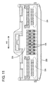
- FIG. 11 is a front view of a housing main body according to another embodiment, and
- FIG. 12 is a perspective view of a prior art divided connector.
-
- One preferred embodiment of the present invention is described with reference to FIGS. 1 to 10. In this embodiment, a female connector F connectable along a connecting direction CD with a mating male connector M is a divided connector. In the following description, sides of the two connectors F, M to be connected with each other are referred to as front side, and reference is made to the respective drawings excluding FIGS. 3, 4, 9 and 10 concerning vertical direction.
- First, the construction of the mating male connector M is described. As shown in FIG. 6, the male connector M has a
male housing 10 made e.g. of a synthetic resin and comprised of aterminal accommodating portion 12 for holding or at least partly accommodating one or moremale terminal fittings 11 and areceptacle 13 projecting forward preferably substantially from the outer peripheral edge of theterminal accommodating portion 12. One or more, preferably a plurality (e.g. twenty)terminal insertion holes 14 into which themale terminal fittings 11 are at least partly insertable are formed substantially side by side along widthwise direction at one or more stages, preferably at each of two (upper and lower) stages in theterminal accommodating portion 12. Eachmale terminal fitting 11 is in the form of a tab extending substantially in forward and backward directions, and a portion thereof projecting into thereceptacle 13 is electrically connectable with a female terminal fitting 40. Thereceptacle 13 preferably is substantially in the form of a rectangular tube having an open front end, and the female connector F is at least partly fittable thereinto from front. Agroove 15 having an open rear end is formed in the lateral (ceiling) surface of thereceptacle 13, and anengaging portion 16 engageable with alock arm 50 of the female connector F is provided before thegroove 15. The front surface of theengaging portion 16 is formed into a slanted or bent surface sloped up or outwardly toward the back so as to guide the resilient deformation of thelock arm 50, whereas the rear surface thereof as a locking surface is formed into a substantially straight surface along a direction at an angle different from 0° or 180°, preferably substantially normal to the connecting direction CD or vertical direction. - Next, the construction of the female connector F is described. As shown in FIGS. 5 and 6, the female connector F is comprised of a housing
main body 20, at least oneauxiliary housing 30 which can be at least partly assembled into the housingmain body 20, and one or morefemale terminal fittings 40 at least partly mountable into the housingmain body 20 and/or theauxiliary housing 30. Each female terminal fitting 40 includes a substantially box-shapedmain portion 41 hollow in forward and backward directions and a wire connection portion (preferably comprising a barrel portion 42) to be connected (preferably crimped or bent or folded into connection) with an end of a wire W, themain portion 41 and thebarrel portion 42 being coupled one after the other. A recess orhole 43 for at least partly receiving alocking portion main portion 41 substantially opposite from the bottom wall thereof, and the front edge or edge portion of therecess 43 is embossed or bent to project down or outwardly, thereby forming a locking projection 44 engageable with thelocking portion resilient contact piece 45 that can be resiliently brought into contact with the male terminal fitting 11 is provided in or at themain portion 41. - As shown in FIGS. 1 and 2, the housing
main body 20 is made e.g. of a synthetic resin into a substantially laterally long block shape as a whole and preferably is substantially symmetrical with respect to an axis of symmetry L1 extending along height direction in the widthwise middle (i.e. in the vertical direction normal to the widthwise direction WD at the widthwise middle position of the housing main body 20). One or more, preferably a pair of terminalaccommodating portions 21 for at least partly accommodating the femaleterminal fittings 40 are provided preferably at the substantially opposite widthwise (longitudinal) ends of the housingmain body 20, and at least oneaccommodating chamber 22 for accommodating theauxiliary housing 30 is provided preferably in a widthwise intermediate portion (preferably in a substantially widthwise middle portion). One or more, e.g. fivecavities 23 into which the femaleterminal fittings 40 are at least partly insertable from an inserting side, preferably substantially from behind, are formed substantially side by side along widthwise direction WD at one or more stages, preferably at each of two (upper and lower) stages, in eachterminal accommodating portion 21. Thesecavities 23 are arranged at such positions as to be substantially symmetrical with respect to the axis of symmetry L1 in the housingmain body 20. The lockingportion 24 for locking the female terminal fitting 40 is provided in eachcavity 23. As shown in FIG. 6, the lockingportion 24 preferably is formed to be supported at both ends by making slits in the lateral (bottom) wall of eachcavity 23. After being temporarily resiliently deformed during the insertion of the female terminal fitting 40, the lockingportion 24 is engaged with the locking projection 44 of the female terminal fitting 40 when the female terminal fitting 40 reaches a substantially proper depth. Further, aterminal insertion hole 23a for permitting the passage of the male terminal fitting 11 is formed in the front wall of eachcavity 23. - A
retainer mount hole 26 into which aretainer 25 for doubly locking the femaleterminal fittings 40 is at least partly insertable is formed in the lateral (bottom) surface of each terminal accommodatingportion 21. Theretainer 25 includes one ormore locking sections 25a engageable with one or morerespective jaw portions 46 at the rear ends of themain portions 41 of the femaleterminal fittings 40. Theretainer 25 is vertically (in directions MD intersecting with or at an angle different from 0° or 180°, preferably substantially normal to inserting and withdrawing directions IWD of the female terminal fittings 40) movable between a partial locking or first position (not shown) where therespective locking sections 25a are retracted downward or away from the correspondingcavities 23 to permit the insertion of the femaleterminal fittings 40 into thecavities 23 and a full locking or second position (see FIG. 6) where therespective locking sections 25a are at least partly located in the correspondingcavities 23 to lock the femaleterminal fittings 40. - As shown in FIGS. 2 and 4, the
accommodating chamber 22 is open backward, and one or more, preferably a pair of holdingpieces 27 for holding theauxiliary housing 30 at least partly accommodated are provided at one or more positions near the lateral upper end(s) of the (preferably substantially opposite) inner side surfaces preferably at the substantially opposite widthwise ends of theaccommodating chamber 22. Each holdingpiece 27 preferably is in the form of a cantilever whose rear end is a base end, and the front end thereof as a free end is engageable with theauxiliary housing 30. One or more, preferably a pair of guidinggrooves 28 are formed to have open rear ends near the lateral (bottom) end positions of the substantially opposite side surfaces of theaccommodating chamber 22. Further, one or moreterminal insertion holes 22a are formed substantially side by side in the front wall of theaccommodating chamber 22 at positions substantially alignable with respective terminal insertion holes 31 a of theauxiliary housing 30 to be described later. - The
auxiliary housing 30 is made e.g. of a synthetic resin, substantially in the form of a laterally long block as a whole, and preferably so shaped as to be symmetrical with respect to an axis of symmetry L2 extending along height direction in the widthwise middle (i.e. in the vertical direction normal to the widthwise direction WD at the widthwise middle position of the auxiliary housing 30) as shown in FIGS. 3 and 4. In theauxiliary housing 30, one or more, e.g. tencavities 31 similar to those of the housingmain body 20 are formed preferably substantially side by side along widthwise direction WD at one or more stages, preferably at each of two (upper and lower) stages, and therespective cavities 31 preferably are arranged substantially at the same heights as thecavities 23 of the housingmain body 20. Therespective cavities 31 are arranged at positions substantially symmetrical with respect to the axis of symmetry L2 in theauxiliary housing 30. Eachcavity 31 is formed with a lockingportion 32 and aterminal insertion hole 31 a having functions similar to those of eachcavity 23 of the housingmain body 20. It should be noted that therespective locking portions 32 are formed in the lateral (upper and/or bottom) outer walls (out of the surrounding walls of therespective cavities 31, those opposite from partition walls partitioning the (upper and lower) cavities at different stages) of theauxiliary housing 30. One or more, preferably a pair of retainingpieces 33 fixed at one side and dimensioned to cross all thecavities 31 are formed in the two (upper and lower) outer walls of theauxiliary housing 30 at positions behind the lockingportions 32. These retainingpieces 33 are engageable with thejaw portions 46 of the femaleterminal fittings 40 similar to the retainer 25 (not shown). - One or more
holdable portions 34 engageable with the one or more respective holdingpieces 27 of theaccommodating chamber 22 are provided on the (preferably substantially opposite) outer side surface(s) of theauxiliary housing 30 preferably at the substantially opposite widthwise ends. Theholdable portions 34 at each side include the one located at the upper end position of theauxiliary housing 30 and the one located slightly below the former one, and project sideways from the corresponding side surface. Further, one or more, preferably a pair ofribs 35 having a function of, for example, guiding an assembling operation of theauxiliary housing 30 by at least partly entering the guidinggrooves 28 of theaccommodating chamber 22 are provided at corresponding positions (e.g. at the bottom end positions of the opposite side surfaces of) theauxiliary housing 30. - As shown in FIGS. 1 and 6, a
lock arm 50 capable of holding the mating male connector M connected is provided at an intermediate position (preferably at a substantially widthwise middle position or substantially the same position as theaccommodating chamber 22 along widthwise direction WD) of the lateral (upper) surface of the housingmain body 20. In other words, thelock arm 50 preferably is located substantially on the axis of symmetry L1 of therespective cavities 23 of the housingmain body 20. Thelock arm 50 is in the form of a cantilever having abase end portion 51 projecting from (preferably the front end of the upper surface of) the housingmain body 20 and anarm portion 52 substantially horizontally extending backward (or substantially parallel to the connecting direction CD) from thebase end portion 51, wherein thearm portion 52 is resiliently deformable along vertical direction (directions intersecting with the connecting direction CD) with thebase end portion 51 as a supporting point. Alock portion 53 engageable with the engagingportion 16 of the male connector M projects upward or outward at an intermediate position (preferably at a substantially longitudinal middle position) of the lateral (upper) surface of thearm portion 52. The front surface of thelock portion 53 is formed into a slanted surface sloped up or outwardly toward the back so as to extent substantially along the front surface of or substantially parallel to the engagingportion 16, whereas the rear surface thereof is formed into a substantially straight surface in a direction at an angle different from 0° or 180°, preferably substantially normal to the connecting direction CD or substantially along vertical direction so as to extend along or substantially parallel to the rear surface of the engagingportion 16. Anoperable portion 54 pressable from above projects upward or outward from the rear end of thearm portion 52 as a free end. Further, a substantially bridge- or gate-shaped protectingportion 55 projects from the rear end of the lateral (upper) surface of the housingmain body 20. Since this protectingportion 55 is so arranged as to at least partly surround the rear end (including at least part of the operable portion 54) of thelock arm 50 from outside, it can prevent, for example, an external wire from entering between the lower surface of thearm portion 52 and the upper surface of the housingmain body 20, with the result that such a deformation of thelock arm 50 as to be turned up can be prevented. - Next, functions of this embodiment thus constructed are described. Upon assembling the female connector F, the one or more female
terminal fittings 40 are at least partly inserted along the inserting and withdrawal direction IWD into therespective cavities 23 of the housingmain body 20 and are locked by the one ormore retainers 25, whereas theauxiliary housing 30 having the one or more femaleterminal fittings 40 at least partly inserted into therespective cavities 31 is at least partly assembled into theaccommodating chamber 22. Upon assembling theauxiliary housing 30, if theauxiliary housing 30 should be in a posture vertically inverted from a proper posture, theribs 35 are not aligned with the guidinggrooves 28 and come substantially into contact with the rear end surface of the housingmain body 20, thereby preventing the insertion of the auxiliary housing 30 (see FIGS. 2 and 3). - When the
auxiliary housing 30 in its substantially proper posture is at least partly inserted into theaccommodating chamber 22 as shown in FIG. 4, theribs 35 at least partly enter the guidinggrooves 28 to guide the inserting operation. When theauxiliary housing 30 reaches a specified (predetermined or predeterminable) depth, the holdingpieces 27 move onto theholdable portions 34 to be temporarily resiliently deformed. When theauxiliary housing 30 is inserted to a substantially proper depth, theholdable portions 34 come to be arranged before the holdingpieces 27 and the holdingpieces 27 are resiliently at least partly restored to engage the front ends thereof with the rear end surfaces of theholdable portions 34 as shown in FIG. 5. In this way, theauxiliary housing 30 is so held as not to come out of the housingmain body 20. - The female connector F assembled as above is connected along the connecting direction CD with the male connector M separately assembled. When the housing
main body 20 is at least partly fitted into thereceptacle 13 of themale housing 10 from front from a state shown in FIG. 6, the respective maleterminal fittings 11 at least partly enter therespective cavities terminal insertion holes lock portion 53 of thelock arm 50 and the slanted front surface of the engagingportion 16 come substantially into sliding contact, whereby thelock arm 50 is resiliently deformed and the respective maleterminal fittings 11 at least partly enter themain portions 41 to contact, preferably to resiliently deform, theresilient contact pieces 45 as shown in FIG. 7. At this time, thearm portion 52 of thelock arm 50 is inclined downward or toward the housingmain body 20 with thebase end portion 51 as a supporting point. Further, in this process, a frictional resistance (connection resistance) is created due to the sliding contact of the maleterminal fittings 11 with theresilient contact pieces 45 and the sliding contact of thelock portion 53 with the engagingportion 16 When the two connectors F, M are connected to a substantially proper depth, thelock arm 50 is resiliently restored to bring thelock portion 53 into thegroove 15, whereby the rear surface of thelock portion 53 is engaged with that of the engagingportion 16 and theresilient contact pieces 45 are properly resiliently brought into contact with the maleterminal fittings 11 as shown in FIG. 8. In this way, the two connectors F, M are inseparably held properly connected. - Depending on a using condition of the female connector F shown in this embodiment, the
auxiliary housing 30 may not be assembled into the housingmain body 20. In such a case, as shown in FIGS. 9 and 10, the female connector F and the male connector M are connected with theaccommodating chamber 22 left empty (or in which a dummy housing, not shown, is at least partly inserted) although the femaleterminal fittings 40 are at least partly inserted into therespective cavities 23 of the housingmain body 20. Even in such a using condition, frictional resistance forces created between the femaleterminal fittings 40 and the maleterminal fittings 11 during the connection of the two connectors F, M can be prevented from being transversely skewed since therespective cavities 23 are arranged at such positions as to be symmetrical with respect to the axis of symmetry L1 in the housingmain body 20 according to this embodiment. Further, since thelock arm 50 is disposed substantially on the axis of symmetry L1 of therespective cavities 23 in the housingmain body 20, a frictional resistance force created between thelock arm 50 and the engagingportion 16 during the connection of the two connectors F, M can be prevented from being transversely skewed. Therefore, connecting operability can be better. - As described above, since the
lock arm 50 is integrally or unitarily formed in the housingmain body 20 formed with theaccommodating chamber 22 into which theauxiliary housing 30 can be selectively at least partly accommodated according to this embodiment, the female connector F can be made smaller as compared to a prior art connector in which a U-shaped lever is mounted on a housing main body. - Accordingly, to miniaturize a divided connector, a housing
main body 20 is connectable with a mating male connector M and internally formed with anaccommodating chamber 22 into which at least oneauxiliary housing 30 can be accommodated. The housingmain body 20 is formed with one ormore cavities 23 for at least partly accommodating femaleterminal fittings 40 electrically connectable with one or more respective mating maleterminal fittings 11, and therespective cavities 23 are arranged at positions symmetrical with respect to an axis of symmetry L1. Alock arm 50 is disposed on the axis of symmetry L1 of therespective cavities 23. The housingmain body 20 is integrally or unitarily formed with thelock arm 50 capable of holding the male connector M connected by the engagement with an engagingportion 16 of the male connector M. - The present invention is not limited to the above described and illustrated embodiment. For example, the following embodiments are also embraced by the technical scope of the present invention as defined by the claims. Beside the following embodiments, various changes can be made without departing from the scope and spirit of the present invention as defined by the claims.
- (1) The arrangements and the numbers of the cavities and the auxiliary
housing in the housing main body can be arbitrarily changed. For example, as shown
in FIG. 11, a pair of
accommodating chambers 22A for accommodating auxiliary housings (not shown) formed with one or more, e.g. five cavities juxtaposed along widthwise direction WD at one or more stages, preferably at each of two (upper and lower) stages are symmetrically arranged at the opposite widthwise sides of a housingmain body 20A, and oneterminal accommodating portion 21 A formed with one or more, e.g. ten cavities juxtaposed along widthwise direction WD at one or more stages, preferably at each of two (upper and lower) stages is provided in an intermediate portion, preferably in a widthwise middle part according to the present invention. It does not, of course, matter even if three or more auxiliary housings are assembled. Further, it is not necessary to perfectly symmetrically arrange the cavities in the housing main body, and the cavities may be arranged at positions slightly displaced from the symmetrical ones. - (2) The shapes of the housing main body and the auxiliary housing can also be arbitrarily changed. For example, the housing main body and the auxiliary housing may be vertically long or substantially square according to the present invention.
- (3) The disposed position of the lock arm in the housing main body can also be arbitrarily changed.
- (4) The housing main body may not be formed with the cavities (although being formed with the accommodating chamber) according to the present invention.
- (5) The present invention is also applicable to male connectors if they are divided connectors.
-
-
- 11
- male terminal fitting (mating terminal)
- 20
- housing main body
- 22
- accommodating chamber
- 23
- cavity
- 30
- auxiliary housing
- 40
- female terminal fitting (terminal fitting)
- 50
- lock arm
- F
- female connector (divided connector)
- L1
- axis of symmetry
- M
- male connector (mating connector)
Claims (10)
- A divided connector (F), comprising:a housing main body (20) connectable with a mating connector (M),at least one auxiliary housing (30),at least one accommodating chamber (22) formed in the housing main body (20) for at least partly accommodating the auxiliary housing (30), anda lock arm (50) integrally or unitarily formed in the housing main body (20) for holding the mating connector (M) connected by being engaged with the mating connector (M).
- A divided connector according to claim 1, wherein the housing main body (20) is formed with one or more cavities (23) for at least partly accommodating terminal fittings (40) connectable with mating terminals (11) provided in the mating connector (M).
- A divided connector according to claim 2, wherein the respective cavities (23) are arranged at substantially symmetrical positions in the housing main body (20).
- A divided connector according to claim 3, wherein the lock arm (50) is disposed on an axis of symmetry (L1) of the respective cavities (23) in the housing main body (20).
- A divided connector according to one or more of the preceding claims, wherein the one or more accommodating chambers (22) are positioned at substantially symmetrical positions in the housing main body (20).
- A divided connector according to one or more of the preceding claims, wherein the auxiliary housing (30) is formed to be substantially symmetric with respect to an auxiliary housing axis of symmetry (L2).
- A divided connector according to claim 6 in combination with claim 3 or 4, wherein an axis of symmetry (L1) of the respective cavities (23) and the auxiliary housing axis of symmetry (L2) are substantially parallel, preferably are substantially overlapped.
- A divided connector according to claim 6 or 7, wherein the auxiliary housing (30) comprises a plurality of cavities (31) which are arranged at substantially symmetrical positions in the auxiliary housing (30).
- A divided connector according to one or more of the preceding claims, wherein a protecting portion (55) is provided to at least partly surround the lock arm (50) so as to protect it.
- A divided connector assembly comprising a divided connector (F) according to one or more of the preceding claims and a mating connector (M) connectable therewith.
Applications Claiming Priority (2)
| Application Number | Priority Date | Filing Date | Title |
|---|---|---|---|
| JP2004025556A JP4632671B2 (en) | 2004-02-02 | 2004-02-02 | Split connector |
| JP2004025556 | 2004-02-02 |
Publications (2)
| Publication Number | Publication Date |
|---|---|
| EP1560298A1 true EP1560298A1 (en) | 2005-08-03 |
| EP1560298B1 EP1560298B1 (en) | 2010-03-31 |
Family
ID=34650885
Family Applications (1)
| Application Number | Title | Priority Date | Filing Date |
|---|---|---|---|
| EP05001707A Expired - Fee Related EP1560298B1 (en) | 2004-02-02 | 2005-01-27 | A divided connector and connector assembly |
Country Status (5)
| Country | Link |
|---|---|
| US (1) | US7114998B2 (en) |
| EP (1) | EP1560298B1 (en) |
| JP (1) | JP4632671B2 (en) |
| CN (1) | CN100468878C (en) |
| DE (1) | DE602005020202D1 (en) |
Cited By (7)
| Publication number | Priority date | Publication date | Assignee | Title |
|---|---|---|---|---|
| EP2141776A2 (en) * | 2008-06-30 | 2010-01-06 | Hirschmann Automotive GmbH | Multi-part housing connector contact |
| WO2011067140A1 (en) * | 2009-12-02 | 2011-06-09 | Tyco Electronics Amp Gmbh | Plug-and-socket connector arrangement with first and second plugs and mating plug |
| EP2395272A1 (en) * | 2010-06-11 | 2011-12-14 | Sumitomo Wiring Systems, Ltd. | Connector for fluid piping, connector assembly and method of connecting fluid piping |
| WO2012041746A1 (en) * | 2010-09-27 | 2012-04-05 | Tyco Electronics Amp Gmbh | Contact housing for electrical contact units, electrical plug connector or mating connector as well as an assembled electrical conductor |
| CN106663894A (en) * | 2014-07-30 | 2017-05-10 | 株式会社自动网络技术研究所 | Connector unit, sub-connector with frame, and sub-connector with cap |
| CN107230896A (en) * | 2017-05-26 | 2017-10-03 | 安徽江淮汽车集团股份有限公司 | Wire bundle plug-in connector |
| EP4270675A1 (en) * | 2022-04-26 | 2023-11-01 | Phoenix Contact GmbH & Co. KG | Fixed pole contact insert and contact insert arrangement |
Families Citing this family (12)
| Publication number | Priority date | Publication date | Assignee | Title |
|---|---|---|---|---|
| JP4168906B2 (en) * | 2003-10-29 | 2008-10-22 | 住友電装株式会社 | Split connector |
| JP4941244B2 (en) * | 2007-03-28 | 2012-05-30 | 住友電装株式会社 | connector |
| JP4987624B2 (en) * | 2007-08-21 | 2012-07-25 | 矢崎総業株式会社 | Split connector |
| JP5116566B2 (en) * | 2008-06-05 | 2013-01-09 | 矢崎総業株式会社 | Combined connector |
| JP2011100559A (en) * | 2009-11-04 | 2011-05-19 | Sumitomo Wiring Syst Ltd | Connector |
| US8951066B2 (en) | 2011-07-22 | 2015-02-10 | Lear Corporation | Electrical connector |
| US8721374B2 (en) * | 2011-07-22 | 2014-05-13 | Lear Corporation | Electrical connector |
| DE102012221115A1 (en) * | 2012-11-19 | 2014-05-22 | Tyco Electronics Amp Gmbh | Plug element with Kontaktmodulverrastung |
| JP6367600B2 (en) * | 2014-04-18 | 2018-08-01 | 矢崎総業株式会社 | connector |
| CN106253007B (en) * | 2016-07-29 | 2018-07-10 | 安徽江淮汽车集团股份有限公司 | A kind of automobile inserting components structure |
| JP6393301B2 (en) * | 2016-10-11 | 2018-09-19 | 株式会社オートネットワーク技術研究所 | connector |
| JP7318311B2 (en) * | 2019-05-29 | 2023-08-01 | 株式会社オートネットワーク技術研究所 | female connector and connector |
Citations (2)
| Publication number | Priority date | Publication date | Assignee | Title |
|---|---|---|---|---|
| EP0803941A2 (en) * | 1996-04-24 | 1997-10-29 | Sumitomo Wiring Systems, Ltd. | Connector |
| US20020106942A1 (en) * | 2001-02-06 | 2002-08-08 | Sumitomo Wiring Systems, Ltd. | Connector |
Family Cites Families (4)
| Publication number | Priority date | Publication date | Assignee | Title |
|---|---|---|---|---|
| JP3047053B2 (en) | 1991-12-27 | 2000-05-29 | 住友電装株式会社 | Combination connector used for automotive wiring harness |
| JP4168483B2 (en) * | 1998-05-29 | 2008-10-22 | モレックス インコーポレーテッド | Wire relay method and electrical connector structure |
| JP3681566B2 (en) * | 1999-02-08 | 2005-08-10 | 矢崎総業株式会社 | Lever fitting type connector |
| JP3862147B2 (en) * | 2001-04-04 | 2006-12-27 | 矢崎総業株式会社 | Connector coupling detection device |
-
2004
- 2004-02-02 JP JP2004025556A patent/JP4632671B2/en not_active Expired - Fee Related
-
2005
- 2005-01-27 DE DE602005020202T patent/DE602005020202D1/en active Active
- 2005-01-27 EP EP05001707A patent/EP1560298B1/en not_active Expired - Fee Related
- 2005-01-27 US US11/044,907 patent/US7114998B2/en not_active Expired - Fee Related
- 2005-02-02 CN CNB2005100059843A patent/CN100468878C/en not_active Expired - Fee Related
Patent Citations (2)
| Publication number | Priority date | Publication date | Assignee | Title |
|---|---|---|---|---|
| EP0803941A2 (en) * | 1996-04-24 | 1997-10-29 | Sumitomo Wiring Systems, Ltd. | Connector |
| US20020106942A1 (en) * | 2001-02-06 | 2002-08-08 | Sumitomo Wiring Systems, Ltd. | Connector |
Cited By (13)
| Publication number | Priority date | Publication date | Assignee | Title |
|---|---|---|---|---|
| EP2141776A3 (en) * | 2008-06-30 | 2011-08-03 | Hirschmann Automotive GmbH | Multi-part housing connector contact |
| EP2141776A2 (en) * | 2008-06-30 | 2010-01-06 | Hirschmann Automotive GmbH | Multi-part housing connector contact |
| US9281605B2 (en) | 2009-12-02 | 2016-03-08 | Te Connectivity Germany Gmbh | Plug-and-socket connector arrangement with first and second plugs and mating plug |
| WO2011067140A1 (en) * | 2009-12-02 | 2011-06-09 | Tyco Electronics Amp Gmbh | Plug-and-socket connector arrangement with first and second plugs and mating plug |
| EP2395272A1 (en) * | 2010-06-11 | 2011-12-14 | Sumitomo Wiring Systems, Ltd. | Connector for fluid piping, connector assembly and method of connecting fluid piping |
| US9022813B2 (en) | 2010-09-27 | 2015-05-05 | Tyco Electronics Amp Gmbh | Contact housing for electrical contact units, electrical plug connector or mating connector as well as an assembled electrical conductor |
| WO2012041746A1 (en) * | 2010-09-27 | 2012-04-05 | Tyco Electronics Amp Gmbh | Contact housing for electrical contact units, electrical plug connector or mating connector as well as an assembled electrical conductor |
| CN106663894A (en) * | 2014-07-30 | 2017-05-10 | 株式会社自动网络技术研究所 | Connector unit, sub-connector with frame, and sub-connector with cap |
| CN106663894B (en) * | 2014-07-30 | 2019-05-03 | 株式会社自动网络技术研究所 | Connector unit |
| CN107230896A (en) * | 2017-05-26 | 2017-10-03 | 安徽江淮汽车集团股份有限公司 | Wire bundle plug-in connector |
| CN107230896B (en) * | 2017-05-26 | 2018-12-14 | 安徽江淮汽车集团股份有限公司 | Wire bundle plug-in connector |
| EP4270675A1 (en) * | 2022-04-26 | 2023-11-01 | Phoenix Contact GmbH & Co. KG | Fixed pole contact insert and contact insert arrangement |
| BE1030480B1 (en) * | 2022-04-26 | 2023-11-28 | Phoenix Contact Gmbh & Co | Fixed-pole contact insert and contact insert arrangement |
Also Published As
| Publication number | Publication date |
|---|---|
| JP2005216813A (en) | 2005-08-11 |
| CN100468878C (en) | 2009-03-11 |
| JP4632671B2 (en) | 2011-02-16 |
| DE602005020202D1 (en) | 2010-05-12 |
| US20050170704A1 (en) | 2005-08-04 |
| CN1652410A (en) | 2005-08-10 |
| US7114998B2 (en) | 2006-10-03 |
| EP1560298B1 (en) | 2010-03-31 |
Similar Documents
| Publication | Publication Date | Title |
|---|---|---|
| EP1560298B1 (en) | A divided connector and connector assembly | |
| US4984998A (en) | High density electrical connector | |
| EP1643599B1 (en) | A terminal fitting and a connector using such a terminal fitting | |
| US8708739B2 (en) | Connector | |
| US8210873B2 (en) | Connector | |
| EP1641083B1 (en) | A connector and connector assembly | |
| US6811451B2 (en) | Connector | |
| EP1863134B1 (en) | A connector | |
| EP2437357A1 (en) | Connector | |
| US20050090148A1 (en) | Electrical connector | |
| EP1986288B1 (en) | A shorting terminal, a connector and an assembling method therefor | |
| US9640922B2 (en) | Connector | |
| US6497591B2 (en) | Connector | |
| US6655999B2 (en) | Connector and a method of assembling it | |
| US7306486B2 (en) | Connector | |
| US7011541B2 (en) | Connector | |
| US6976874B2 (en) | Terminal fitting and connector provided therewith | |
| US6851987B2 (en) | Connector | |
| US7377824B2 (en) | Connector and connector assembly | |
| US10826229B2 (en) | Connector with coupling portion | |
| US6488547B2 (en) | Connector with longitudinally spaced locks for retaining terminal fittings | |
| JP7368165B2 (en) | connector | |
| US7001224B2 (en) | Connector with retainer for locking terminal fitings | |
| JPH04206483A (en) | Electric connector | |
| JPH062577U (en) | Low insertion force type electrical connector |
Legal Events
| Date | Code | Title | Description |
|---|---|---|---|
| PUAI | Public reference made under article 153(3) epc to a published international application that has entered the european phase |
Free format text: ORIGINAL CODE: 0009012 |
|
| 17P | Request for examination filed |
Effective date: 20050210 |
|
| AK | Designated contracting states |
Kind code of ref document: A1 Designated state(s): AT BE BG CH CY CZ DE DK EE ES FI FR GB GR HU IE IS IT LI LT LU MC NL PL PT RO SE SI SK TR |
|
| AX | Request for extension of the european patent |
Extension state: AL BA HR LV MK YU |
|
| AKX | Designation fees paid |
Designated state(s): DE FR |
|
| 17Q | First examination report despatched |
Effective date: 20080206 |
|
| GRAP | Despatch of communication of intention to grant a patent |
Free format text: ORIGINAL CODE: EPIDOSNIGR1 |
|
| GRAS | Grant fee paid |
Free format text: ORIGINAL CODE: EPIDOSNIGR3 |
|
| GRAA | (expected) grant |
Free format text: ORIGINAL CODE: 0009210 |
|
| AK | Designated contracting states |
Kind code of ref document: B1 Designated state(s): DE FR |
|
| REF | Corresponds to: |
Ref document number: 602005020202 Country of ref document: DE Date of ref document: 20100512 Kind code of ref document: P |
|
| PLBE | No opposition filed within time limit |
Free format text: ORIGINAL CODE: 0009261 |
|
| STAA | Information on the status of an ep patent application or granted ep patent |
Free format text: STATUS: NO OPPOSITION FILED WITHIN TIME LIMIT |
|
| 26N | No opposition filed |
Effective date: 20110104 |
|
| PGFP | Annual fee paid to national office [announced via postgrant information from national office to epo] |
Ref country code: FR Payment date: 20130204 Year of fee payment: 9 Ref country code: DE Payment date: 20130123 Year of fee payment: 9 |
|
| REG | Reference to a national code |
Ref country code: DE Ref legal event code: R119 Ref document number: 602005020202 Country of ref document: DE |
|
| PG25 | Lapsed in a contracting state [announced via postgrant information from national office to epo] |
Ref country code: DE Free format text: LAPSE BECAUSE OF NON-PAYMENT OF DUE FEES Effective date: 20140801 |
|
| REG | Reference to a national code |
Ref country code: FR Ref legal event code: ST Effective date: 20140930 |
|
| REG | Reference to a national code |
Ref country code: DE Ref legal event code: R119 Ref document number: 602005020202 Country of ref document: DE Effective date: 20140801 |
|
| PG25 | Lapsed in a contracting state [announced via postgrant information from national office to epo] |
Ref country code: FR Free format text: LAPSE BECAUSE OF NON-PAYMENT OF DUE FEES Effective date: 20140131 |