EP1560253A2 - Apparatus for coating a substrate, the apparatus comprising a gettering device - Google Patents
Apparatus for coating a substrate, the apparatus comprising a gettering device Download PDFInfo
- Publication number
- EP1560253A2 EP1560253A2 EP05000927A EP05000927A EP1560253A2 EP 1560253 A2 EP1560253 A2 EP 1560253A2 EP 05000927 A EP05000927 A EP 05000927A EP 05000927 A EP05000927 A EP 05000927A EP 1560253 A2 EP1560253 A2 EP 1560253A2
- Authority
- EP
- European Patent Office
- Prior art keywords
- compartment
- cathode
- substrate
- assembly
- coating
- Prior art date
- Legal status (The legal status is an assumption and is not a legal conclusion. Google has not performed a legal analysis and makes no representation as to the accuracy of the status listed.)
- Granted
Links
Images


Classifications
-
- H—ELECTRICITY
- H01—ELECTRIC ELEMENTS
- H01J—ELECTRIC DISCHARGE TUBES OR DISCHARGE LAMPS
- H01J37/00—Discharge tubes with provision for introducing objects or material to be exposed to the discharge, e.g. for the purpose of examination or processing thereof
- H01J37/32—Gas-filled discharge tubes
- H01J37/32431—Constructional details of the reactor
- H01J37/32798—Further details of plasma apparatus not provided for in groups H01J37/3244 - H01J37/32788; special provisions for cleaning or maintenance of the apparatus
- H01J37/32853—Hygiene
- H01J37/32871—Means for trapping or directing unwanted particles
-
- C—CHEMISTRY; METALLURGY
- C23—COATING METALLIC MATERIAL; COATING MATERIAL WITH METALLIC MATERIAL; CHEMICAL SURFACE TREATMENT; DIFFUSION TREATMENT OF METALLIC MATERIAL; COATING BY VACUUM EVAPORATION, BY SPUTTERING, BY ION IMPLANTATION OR BY CHEMICAL VAPOUR DEPOSITION, IN GENERAL; INHIBITING CORROSION OF METALLIC MATERIAL OR INCRUSTATION IN GENERAL
- C23C—COATING METALLIC MATERIAL; COATING MATERIAL WITH METALLIC MATERIAL; SURFACE TREATMENT OF METALLIC MATERIAL BY DIFFUSION INTO THE SURFACE, BY CHEMICAL CONVERSION OR SUBSTITUTION; COATING BY VACUUM EVAPORATION, BY SPUTTERING, BY ION IMPLANTATION OR BY CHEMICAL VAPOUR DEPOSITION, IN GENERAL
- C23C14/00—Coating by vacuum evaporation, by sputtering or by ion implantation of the coating forming material
- C23C14/0021—Reactive sputtering or evaporation
- C23C14/0036—Reactive sputtering
- C23C14/0063—Reactive sputtering characterised by means for introducing or removing gases
-
- C—CHEMISTRY; METALLURGY
- C23—COATING METALLIC MATERIAL; COATING MATERIAL WITH METALLIC MATERIAL; CHEMICAL SURFACE TREATMENT; DIFFUSION TREATMENT OF METALLIC MATERIAL; COATING BY VACUUM EVAPORATION, BY SPUTTERING, BY ION IMPLANTATION OR BY CHEMICAL VAPOUR DEPOSITION, IN GENERAL; INHIBITING CORROSION OF METALLIC MATERIAL OR INCRUSTATION IN GENERAL
- C23C—COATING METALLIC MATERIAL; COATING MATERIAL WITH METALLIC MATERIAL; SURFACE TREATMENT OF METALLIC MATERIAL BY DIFFUSION INTO THE SURFACE, BY CHEMICAL CONVERSION OR SUBSTITUTION; COATING BY VACUUM EVAPORATION, BY SPUTTERING, BY ION IMPLANTATION OR BY CHEMICAL VAPOUR DEPOSITION, IN GENERAL
- C23C14/00—Coating by vacuum evaporation, by sputtering or by ion implantation of the coating forming material
- C23C14/22—Coating by vacuum evaporation, by sputtering or by ion implantation of the coating forming material characterised by the process of coating
- C23C14/56—Apparatus specially adapted for continuous coating; Arrangements for maintaining the vacuum, e.g. vacuum locks
- C23C14/562—Apparatus specially adapted for continuous coating; Arrangements for maintaining the vacuum, e.g. vacuum locks for coating elongated substrates
-
- C—CHEMISTRY; METALLURGY
- C23—COATING METALLIC MATERIAL; COATING MATERIAL WITH METALLIC MATERIAL; CHEMICAL SURFACE TREATMENT; DIFFUSION TREATMENT OF METALLIC MATERIAL; COATING BY VACUUM EVAPORATION, BY SPUTTERING, BY ION IMPLANTATION OR BY CHEMICAL VAPOUR DEPOSITION, IN GENERAL; INHIBITING CORROSION OF METALLIC MATERIAL OR INCRUSTATION IN GENERAL
- C23C—COATING METALLIC MATERIAL; COATING MATERIAL WITH METALLIC MATERIAL; SURFACE TREATMENT OF METALLIC MATERIAL BY DIFFUSION INTO THE SURFACE, BY CHEMICAL CONVERSION OR SUBSTITUTION; COATING BY VACUUM EVAPORATION, BY SPUTTERING, BY ION IMPLANTATION OR BY CHEMICAL VAPOUR DEPOSITION, IN GENERAL
- C23C14/00—Coating by vacuum evaporation, by sputtering or by ion implantation of the coating forming material
- C23C14/22—Coating by vacuum evaporation, by sputtering or by ion implantation of the coating forming material characterised by the process of coating
- C23C14/56—Apparatus specially adapted for continuous coating; Arrangements for maintaining the vacuum, e.g. vacuum locks
- C23C14/564—Means for minimising impurities in the coating chamber such as dust, moisture, residual gases
Definitions
- the invention relates to a device for Coating a substrate with an absorber arrangement according to the preamble of claim 1.
- a Device for example, from EP 0 783 174 A2 a Device according to the preamble of claim 1 known.
- a substrate with an alternating current source with two Cathodes connected, is the one pole of the AC power source to one cathode and the other pole to the other cathode via supply lines connected, with each of the two cathodes in one own compartment of a plurality of adjacently arranged, together forming a vacuum chamber, over a passage is provided interconnected compartments.
- a method for the Generation of a low-emitting layer on one Glass substrate known in which first a reflective metal layer and then a metal oxide layer in the presence of an oxygen absorber the substrate is applied.
- an oxygen absorber is preferably a hydrocarbon such as methane used.
- the metal oxide layer can, for example, from Tin oxide, zinc oxide, tungsten oxide or other metal oxides consist.
- a disadvantage of the above-mentioned publications known devices and methods is particularly that the production of the metal layers either the Presence of a gaseous oxygen absorber requires or the application of the metal and the Metal oxide layers spatially relatively far from each other must take place separately. An appropriate facility is thus of great length and therefore costly in Provision and operation.
- the invention is therefore based on the object, a To provide apparatus for coating a substrate, in which the coating of the substrate with metal and with metallic oxides in the same device in spatial Can take place close to each other.
- an absorber arrangement present the free oxygen or a any other reactive gas, e.g. nitrogen receives, so that the substrate, which under the Absorber arrangement is carried out in the following or in before lying subjects z. B. with a metal layer can be provided whose quality is not due Oxygen, nitrogen or another reactive gas is lowered.
- the absorber arrangement has a Cathode assembly, which acts as a getter cathode, by continually inserting one into the absorber assembly Metal layer generated, which reacts with the reactive gas is available.
- the absorber arrangement for Enlargement of the surface several plate-shaped Metal elements which are sandblasted before assembly become.
- Another advantage is that to increase the reactive Surface a sieve between the plate-shaped metal elements and the substrate can be used.
- the device is cooled by the plate-shaped metal elements, for example, of a Coolant be flowed through.
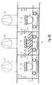
- Fig. 1 shows for better understanding of inventive measures first in one schematic sectional view of an embodiment of a Device 1 for coating a substrate 2 according to the prior art in a side view.
- Such a device 1 is used for coating a Substrate 2 such as e.g. Glass with different coatings such as. Heat protection layers or sun protection layers.
- a Substrate 2 such as e.g. Glass
- different coatings such as. Heat protection layers or sun protection layers.
- the device 1 comprises a vacuum main chamber 3, which is divided into a plurality of subjects 4 to 8, where all subjects 4 to 8 over one with the help of Shafts 26, 27 formed passage 9, 10 with each other communicating and individual subjects 4 and 8 respectively equipped with a sputtering cathode 11, 12, wherein the two cathodes 11, 12 via supply lines 13, 14 e.g. with an AC power source 15, for example a medium frequency generator connected.
- the second, third and fourth compartment 5, 6, 7 is in the embodiment each to a separate vacuum pump 16, 17, 18, e.g. a Turbopump, connected, the two compartments 4, 5 and 7, 8 with each other via openings 19, 20 in the respective partitions 21, 22 are connected.
- the subjects 4, 6 and 8 are in the illustrated embodiment Gas supply lines 23, 23a, 24, 24a, 25 and 25a connected, via which process gas or over the Gas supply lines 24 and 24a reactive gas in the individual Trays 4 to 8 can be inserted. Alternatively, you can the reactive gas also supplied in the cathode compartments become.
- the substrate 2 is during the Coating process along the passage 9, 10 or transported through the shafts 26, 27 and to the Cathodes 11, 12 moved past.
- a problem of the described vacuum chamber 3 is the Connection of the individual subjects 4 to 8 with each other.
- the Connection can not be avoided because the to be coated Substrate 2 on all subjects 4 to 8 are passed must in order to apply the desired coating can.
- the reactive gas atmosphere in In this case, the oxygen atmosphere, which for the Coating with a metal oxide in the corresponding Tray 4 to 8 is initiated, with reduced Partial pressure can also penetrate into those compartments, in which should be a coating with the metal. But penetrates oxygen, there is a risk that the Metal coating undesirably partially oxidized and their properties change.
- An inventively designed device 1 according to the 2 to 4 in contrast, has an absorber arrangement 34 for active separation of the reactive gas by gettering with a cathode assembly 37, whereby it is possible in closely adjacent compartments of the device 1 different To perform coatings that different Have reactive gas needs. This can be done spatially closely adjacent subjects reactive and nonreactive Atmospheres are generated.
- the inventive Device 1 can thus be a considerably shorter length which has a positive effect on the costs of both Deployment as well as operation.
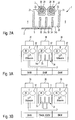
- Fig. 2A shows in a highly schematic representation the basic structure of an inventive designed device 1.
- the tray 5 is through Walls 31 separated from adjacent compartments 4 and 6.
- the walls 31 can be seen from below be explained reasons explained.
- the double cathode 30 has two in the embodiment Targets 39, which, for example, aluminum Al or titanium Ti.
- Other suitable target materials are e.g. the elements Ta, Th and Zr.
- Below the Targets 39 are formed during operation of the Cathode arrangement 37 plasma clouds 33 out.
- Between Walls 31 of the compartment 5 are in the embodiment perpendicular to the substrate 2 or parallel to the walls 31st plate-shaped elements 34a, for example Metal sheets, arranged, which the tray 5 in individual Divide areas 35 and form the absorber assembly 34.
- the optimal shape and arrangement of the plate-shaped Elements 34a is determined by the consideration that as few particles of the reactive gas on the Absorber arrangement 34 can diffuse past.
- plate-shaped elements 34a in an inclined position makes sense, as it makes the available effective Area for gettering is larger than vertical plate-shaped elements 34a.
- the target materials must be chosen so that on the one hand a very good getter effect is achieved and on the other hand, related optical properties previous coating are present so it does not to material technical incompatibilities comes. So for example, Al should be over a ZnAl oxide layer or Ti over a titanium layer for building a Titanoxidgradienten be used. intolerances
- the materials can be for example in optical Absorption, coating adhesion problems or Express particle diffusion.
- tray 4 in an oxidic Atmosphere and in compartment 6 in a non-oxidic, e.g. sputtered nitridic atmosphere persists conventional devices 1 the risk of transfer of Oxygen in the nitridic atmosphere with the result of Contamination of the metal nitride layer.
- This is through the according to the invention, counteracted by that diffuse from the tray 4 to the tray 6 Oxygen atoms in the intermediate compartment 5 at the Elements 34a of the absorber assembly 34, which always with a metal layer with high affinity for oxygen is coated by the cathode assembly 37, to Metal oxides react and are absorbed.
- FIGS. 3A and 3B show the diagrams in a highly schematic manner Operation of the absorber assembly 34 with the Cathode arrangement 37 according to FIG. 2A.
- Fig. 3A is first the situation with switched off double cathode 30, while Fig. 3B shows the operation with switched double cathode 30 shows.
- a device 1 for coating a substrate 2 represented, of which the middle compartment 5 the above mentioned absorber assembly 34 and cathode assembly 37th having.
- the device 1 has in the illustrated Embodiment per compartment 4, 5, 6 each at least one Turbopump 36, which for the generation of the vacuum needed.
- Subject 4 has a specific one Oxygen partial pressure, which is a reactive gas flow of for example, about 250 sccm, for sputtering a metal oxide layer on the substrate 2.
- a Cathode assembly 37 and an absorber assembly 34 in tray 5 used which at a defined power and Voltage, in the exemplary embodiment 75 kW at 630 V, can be operated, the oxygen concentration in compartment 6 are lowered to a reactive gas flow of about 25 sccm, which compared to the Regentgasfluß in compartment 4 only is one tenth. Without switched double cathode 30 is still the fourfold Regradgasfluß in compartment 6 before.
- the overflowing from the tray 4 reacts Oxygen with the metal layer on the plate-shaped Elements 34a of the absorber assembly 34 and beats as metal oxide at the elements 34a in compartment 5 down.
- the reactive gas flow in compartment 5 decreases, so that less oxygen can flow into the next compartment 6.
- nitrogen as well as others Reactive gases with the corresponding target materials will be realized.
- the plate-shaped elements 34a are preferably as well as the walls 31 cooled by the plate-shaped elements 34a, for example, double-walled are formed and flows through a coolant become. This increases and stabilizes the reactivity of the Surfaces.
- the elements 34a preferably sandblasted before assembly, so that they have a have high roughness.
- a screen 34b shown in Fig. 2A e.g. from a metal wire mesh, be arranged.
- the Plates can, as already mentioned above, inclined or labyrinthine and with holes or Slots be provided. The more plate-shaped elements 34a are present, the greater is the Absorb available surface and therefore better the active gas separation.
- Fig. 4 is highly schematic an overall view via a device 1 designed according to the invention shown.
- the substrate 2 first passes through one Number of empty compartments and is then using corresponding targets 32 in several successive Compartments, for example, with a metal oxide or -Nitride layer provided. Then done in the AST designated compartment the active gas separation by means of not absorber arrangement 34 and the Cathode arrangement 37. In the next compartment can then immediately with sputtering, for example, a metal layer be started without a significant contamination with reactive gas occurs.
- the device 1 makes it possible for a relatively short Plant length of the device 1 not only one, but several layers of metals, metal oxides, Metal nitrides or other layers which are different Reactive gas atmospheres, on the substrate 2 applied.
- metal, metal oxide and metal nitride layers be applied, e.g. Zinc oxide ZnOx in addition Aluminum nitride AlN.
- FIG. 5A shows the invention two diagrams showing the oxygen partial pressure in compartment 6 represent.
- FIG. 5A the signal of the Oxygen sensor in compartment 6 and the oxygen partial pressure depending on the amount of in box 4 introduced gas
- Fig. 5B the Oxygen balance in compartment 6 at constant gas inlet in Tray 4 and varied performance of the cathode assembly 37 in Tray 5 shows.
- the rising Absorption or getter effect of the cathode assembly 37 which is due to a sinking oxygen partial pressure in Tray 6 shows.
- At a power of about 75 kW will be a Saturation value reached, beyond which another Performance increase no significant reduction of Oxygen partial pressure in compartment 6 causes more.
- the invention is not limited to the illustrated embodiment limited. In particular, others are also spatial configurations possible.
Landscapes
- Chemical & Material Sciences (AREA)
- Engineering & Computer Science (AREA)
- Organic Chemistry (AREA)
- Materials Engineering (AREA)
- Mechanical Engineering (AREA)
- Metallurgy (AREA)
- Chemical Kinetics & Catalysis (AREA)
- Health & Medical Sciences (AREA)
- Epidemiology (AREA)
- Public Health (AREA)
- Physics & Mathematics (AREA)
- Plasma & Fusion (AREA)
- Analytical Chemistry (AREA)
- Physical Vapour Deposition (AREA)
Abstract
Description
Die Erfindung bezieht sich auf eine Vorrichtung zum
Beschichten eines Substrats mit einer Absorberanordnung
nach dem Oberbegriff des Anspruchs 1.The invention relates to a device for
Coating a substrate with an absorber arrangement
according to the preamble of
Beispielsweise ist aus der EP 0 783 174 A2 eine
Vorrichtung gemäß dem Oberbegriff des Anspruchs 1 bekannt.
Bei der dort beschriebenen Vorrichtung zum Beschichten
eines Substrats mit einer Wechselstromquelle, die mit zwei
Kathoden verbunden ist, ist der eine Pol der
Wechselstromquelle an die eine Kathode und der andere Pol
an die andere Kathode über Versorgungsleitungen
angeschlossen, wobei jede der beiden Kathoden in einem
eigenen Abteil einer Vielzahl von benachbart angeordneten,
zusammen eine Vakuumkammer bildenden, über einen Durchgang
miteinander verbundenen Abteilen vorgesehen ist.For example, from
Aus der EP 0 983 973 A2 ist ein Verfahren für die
Erzeugung einer niedrigemittierenden Schicht auf einem
Glassubstrat bekannt, bei welchem zunächst eine
reflektierende Metallschicht und dann eine Metalloxidschicht
unter Anwesenheit eines Sauerstoffabsorbers auf
das Substrat aufgebracht wird. Als Sauerstoffabsorber wird
vorzugsweise ein Kohlenwasserstoff wie Methan verwendet.
Die Metalloxidschicht kann dabei beispielsweise aus
Zinnoxid, Zinkoxid, Wolframoxid oder anderen Metalloxiden
bestehen.From
Nachteilig an den aus den oben genannten Druckschriften bekannten Vorrichtungen und Verfahren ist insbesondere, daß die Herstellung der Metallschichten entweder die Anwesenheit eines gasförmigen Sauerstoffabsorbers erfordert oder die Aufbringung der Metall- und der Metalloxidschichten räumlich relativ weit voneinander getrennt stattfinden muß. Eine entsprechende Anlage ist somit von großer Baulänge und folglich kostenintensiv in Bereitstellung und Betrieb. A disadvantage of the above-mentioned publications known devices and methods is particularly that the production of the metal layers either the Presence of a gaseous oxygen absorber requires or the application of the metal and the Metal oxide layers spatially relatively far from each other must take place separately. An appropriate facility is thus of great length and therefore costly in Provision and operation.
Der Erfindung liegt daher die Aufgabe zu Grunde, eine Vorrichtung zum Beschichten eines Substrats zu schaffen, bei welcher die Beschichtung des Substrats mit Metall und mit Metalloxiden in der gleichen Vorrichtung in räumlicher Nähe zueinander stattfinden kann.The invention is therefore based on the object, a To provide apparatus for coating a substrate, in which the coating of the substrate with metal and with metallic oxides in the same device in spatial Can take place close to each other.
Die Aufgabe wird durch die Merkmale des Anspruchs 1
gelöst.The object is achieved by the features of
Bei der erfindungsgemäß ausgestalteten Vorrichtung ist dabei in zumindest einem der Fächer eine Absorberanordnung vorhanden, welche den freien Sauerstoff oder ein beliebiges anderes Reaktivgas wie z.B. Stickstoff aufnimmt, so daß das Substrat, welches unter der Absorberanordnung durchgeführt wird, in folgenden oder in davor liegenden Fächern z. B. mit einer Metallschicht versehen werden kann, deren Qualität nicht durch Sauerstoff, Stickstoff oder ein anderes Reaktivgas herabgesetzt wird. Die Absorberanordnung weist dabei eine Kathodenanordnung auf, welche als Getterkathode fungiert, indem sie fortwährend in der Absorberanordnung eine Metallschicht erzeugt, die zur Reaktion mit dem Reaktivgas zur Verfügung steht.In the inventively designed device is in at least one of the compartments an absorber arrangement present the free oxygen or a any other reactive gas, e.g. nitrogen receives, so that the substrate, which under the Absorber arrangement is carried out in the following or in before lying subjects z. B. with a metal layer can be provided whose quality is not due Oxygen, nitrogen or another reactive gas is lowered. The absorber arrangement has a Cathode assembly, which acts as a getter cathode, by continually inserting one into the absorber assembly Metal layer generated, which reacts with the reactive gas is available.
Vorteilhafte Weiterbildungen der Erfindung sind in den Unteransprüchen beschrieben.Advantageous developments of the invention are in the Subclaims described.
Vorteilhafterweise umfaßt die Absorberanordnung zur Vergrößerung der Oberfläche mehrere plattenförmige Metallelemente, welche vor der Montage sandgestrahlt werden.Advantageously, the absorber arrangement for Enlargement of the surface several plate-shaped Metal elements which are sandblasted before assembly become.
Von Vorteil ist weiter, daß zur Vergrößerung der reaktiven Oberfläche ein Sieb zwischen den plattenförmigen Metallelementen und dem Substrat eingesetzt werden kann. Another advantage is that to increase the reactive Surface a sieve between the plate-shaped metal elements and the substrate can be used.
Vorteilhafterweise ist die Vorrichtung gekühlt, indem die plattenförmigen Metallelemente beispielsweise von einer Kühlflüssigkeit durchströmt werden.Advantageously, the device is cooled by the plate-shaped metal elements, for example, of a Coolant be flowed through.
Nachfolgend werden vorteilhafte Ausgestaltungsformen der Erfindung anhand bevorzugter Ausführungsbeispiele unter Bezugnahme auf die Zeichnung näher erläutert. Es zeigen:
- Fig. 1
- eine schematische, geschnittene seitliche Darstellung eines Ausführungsbeispiels einer Vorrichtung zur Beschichtung eines Substrates gemäß dem Stand der Technik,
- Fig. 2A
- eine prinzipielle Darstellung eines Fachs einer erfindungsgemäß ausgestalteten Vorrichtung zur Beschichtung eines Substrates mit einer Absorberanordnung gemäß einem ersten Ausführungsbeispiel,
- Fig. 2B
- eine prinzipielle Darstellung einer erfindungsgemäß ausgestalteten Vorrichtung zur Beschichtung eines Substrates mit einer Absorberanordnung gemäß einem zweiten Ausführungsbeispiel,
- Fig. 3A
- eine Darstellung dreier benachbarter Fächer der Vorrichtung gemäß Fig. 2A mit den Vakuumpumpen,
- Fig. 3B
- eine Darstellung dreier benachbarter Fächer der Vorrichtung gemäß Fig. 3A mit eingeschalteter Kathode,
- Fig. 4
- eine schematische Darstellung mehrerer Fächer einer erfindungsgemäß ausgestalteten Vorrichtung mit der Kathodenanordnung, und
- Fig. 5A-B
- Diagramme des Sauerstoffpartialdrucks in einem ausgewählten Fach einer erfindungsgemäß ausgestalteten Vorrichtung.
- Fig. 1
- 1 is a schematic, sectional side view of an embodiment of a device for coating a substrate according to the prior art,
- Fig. 2A
- a schematic representation of a compartment of an inventively designed device for coating a substrate with an absorber arrangement according to a first embodiment,
- Fig. 2B
- a schematic representation of an inventively designed device for coating a substrate with an absorber arrangement according to a second embodiment,
- Fig. 3A
- 3 shows a representation of three adjacent compartments of the device according to FIG. 2A with the vacuum pumps, FIG.
- Fig. 3B
- a representation of three adjacent compartments of the device according to FIG. 3A with the cathode switched on,
- Fig. 4
- a schematic representation of several compartments of an inventively designed device with the cathode assembly, and
- Fig. 5A-B
- Diagrams of the oxygen partial pressure in a selected compartment of a device designed according to the invention.
Fig. 1 zeigt zur besseren Verständlichkeit der
erfindungsgemäßen Maßnahmen zunächst in einer
schematischen Schnittansicht ein Ausführungsbeispiel einer
Vorrichtung 1 zur Beschichtung eines Substrates 2 gemäß
dem Stand der Technik in einer seitlichen Gesamtansicht.Fig. 1 shows for better understanding of
inventive measures first in one
schematic sectional view of an embodiment of a
Eine derartige Vorrichtung 1 dient zum Beschichten eines
Substrats 2 wie z.B. Glas mit verschiedenen Beschichtungen
wie z.B. Wärmeschutzschichten oder Sonnenschutzschichten.Such a
Die Vorrichtung 1 umfaßt dabei eine Vakuum-Hauptkammer 3,
die in eine Vielzahl von Fächern 4 bis 8 aufgeteilt ist,
wobei alle Fächer 4 bis 8 über einen mit Hilfe von
Schächten 26, 27 gebildeten Durchgang 9, 10 untereinander
in Verbindung stehen und einzelne Fächer 4 und 8 jeweils
mit einer Sputter-Kathode 11, 12 ausgestattet sind, wobei
die beiden Kathoden 11, 12 über Versorgungsleitungen 13,
14 z.B. mit einer Wechselstromquelle 15, beispielsweise
einem Mittelfrequenzgenerator, verbunden sind. Das zweite,
dritte und vierte Fach 5, 6, 7 ist im Ausführungsbeispiel
jeweils an eine eigene Vakuumpumpe 16, 17, 18, z.B. eine
Turbopumpe, angeschlossen, wobei die beiden Fächer 4, 5
und 7, 8 untereinander über Öffnungen 19, 20 in den
jeweiligen Trennwänden 21, 22 verbunden sind. Die Fächer
4, 6 und 8 sind im dargestellten Ausführungsbeispiel an
Gaszufuhrleitungen 23, 23a, 24, 24a, 25 und 25a
angeschlossen, über welche Prozeßgas bzw. über die
Gaszufuhrleitungen 24 und 24a Reaktivgas in die einzelnen
Fächer 4 bis 8 eingelassen werden kann. Alternativ kann
das Reaktivgas auch in den Kathodenfächern zugeführt
werden. Das Substrat 2 wird während des
Beschichtungsvorgangs entlang dem Durchgang 9, 10 bzw.
durch die Schächte 26, 27 transportiert und an den
Kathoden 11, 12 vorbeibewegt.The
Ein Problem der beschriebenen Vakuumkammer 3 ist die
Verbindung der einzelnen Fächer 4 bis 8 untereinander. Die
Verbindung ist nicht zu umgehen, da das zu beschichtende
Substrat 2 an allen Fächern 4 bis 8 vorbeigeführt werden
muß, um die gewünschte Beschichtung aufbringen zu können.
Sollen jedoch mehrere Schichten auf das Substrat 2
aufgebracht werden, insbesondere beispielsweise
abwechselnde Schichten aus Metallen und Metalloxiden,
besteht ein Problem, da die Reaktivgasatmosphäre, in
diesem Fall die Sauerstoffatmosphäre, welche für die
Beschichtung mit einem Metalloxid in das entsprechende
Fach 4 bis 8 eingeleitet wird, mit vermindertem
Partialdruck auch in diejenigen Fächer eindringen kann, in
welchen eine Beschichtung mit dem Metall erfolgen soll.
Dringt jedoch Sauerstoff ein, besteht die Gefahr, daß die
Metallbeschichtung unerwünschterweise teilweise oxidiert
und sich deren Eigenschaften verändern. Ähnliches gilt für
Nitrierung mit Stickstoff bzw. Verbindungen mit anderen
Reaktivgasen. Zur Vermeidung des Überströmens von
Reaktivgas hat man sich bisher einer räumlich möglichst
weiten Trennung der Fächer für die Metallbeschichtung von
denjenigen für die sonstigen Beschichtung bedient, wodurch
die Vorrichtung 1 eine sehr große Baulänge erhält und
daher kosten- und platzintensiv ist.A problem of the described
Eine erfindungsgemäß ausgestaltete Vorrichtung 1 gemäß den
Fig. 2 bis 4 weist demgegenüber eine Absorberanordnung 34
zur aktiven Abscheidung des Reaktivgases durch Gettern mit
einer Kathodenanordnung 37 auf, wodurch es möglich ist, in
eng benachbarten Fächern der Vorrichtung 1 verschiedene
Beschichtungen durchzuführen, welche unterschiedliche
Reaktivgasbedürfnisse haben. Dadurch können in räumlich
eng benachbarten Fächern reaktive und nichtreaktive
Atmosphären erzeugt werden. Die erfindungsgemäße
Vorrichtung 1 kann damit eine erheblich verkürzte Baulänge
aufweisen, was sich positiv auf die Kosten sowohl der
Bereitstellung als auch des Betriebs auswirkt.An inventively designed
Fig. 2A zeigt in einer stark schematisierten Darstellung
den prinzipiellen Aufbau einer erfindungsgemäß
ausgestalteten Vorrichtung 1. Dabei ist zumindest ein Fach
5 mit einer als Doppelkathode 30 ausgebildeten
Kathodenanordnung 37 versehen. Das Fach 5 ist durch
Wandungen 31 von angrenzenden Fächern 4 und 6 getrennt.
Die Wandungen 31 können dabei aus weiter unten näher
erläuterten Gründen gekühlt sein.Fig. 2A shows in a highly schematic representation
the basic structure of an inventive
designed
Die Doppelkathode 30 weist im Ausführungsbeispiel zwei
Targets 39 auf, welche beispielsweise aus Aluminium Al
oder Titan Ti bestehen. Andere geeignete Targetmaterialien
sind z.B. die Elemente Ta, Th und Zr. Unterhalb der
Targets 39 bilden sich während des Betriebs der
Kathodenanordnung 37 Plasmawolken 33 aus. Zwischen den
Wandungen 31 des Fachs 5 sind im Ausführungsbeispiel
senkrecht zum Substrat 2 bzw. parallel zu den Wandungen 31
plattenförmige Elemente 34a, beispielsweise aus
Metallblechen, angeordnet, welche das Fach 5 in einzelne
Bereiche 35 aufteilen und die Absorberanordnung 34 bilden.The
Die optimale Form und Anordnung der plattenförmigen
Elemente 34a ist dabei durch die Überlegung bestimmt, daß
möglichst wenige Teilchen des reaktiven Gases an der
Absorberanordnung 34 vorbeidiffundieren können.The optimal shape and arrangement of the plate-shaped
So sind beispielsweise, wie in Fig. 2B dargestellt,
plattenförmige Elemente 34a in geneigter Position
sinnvoll, da dadurch die zur Verfügung stehende effektive
Fläche zum Gettern größer ist als bei senkrecht stehenden
plattenförmigen Elementen 34a.For example, as shown in FIG. 2B,
plate-shaped
Möglich ist auch eine Anordnung in labyrinthischer
Anordnung, versetzt zueinander angeordnete Elemente 34a
oder auch kammartig ineinandergreifende, mit Löchern oder
Schlitzen versehene Elemente 34a denkbar. Je mehr
plattenförmige Elemente 34a verwendet werden, desto höher
ist die Getterwirkung.Also possible is an arrangement in labyrinthine
Arrangement, mutually offset
Die Targetmaterialien müssen dabei so gewählt werden, daß einerseits eine sehr gute Getterwirkung erzielt wird und andererseits verwandte optische Eigenschaften zur vorhergehenden Beschichtung vorhanden sind, damit es nicht zu materialtechnischem Unverträglichkeiten kommt. So sollte beispielsweise Al über einer ZnAl-Oxidschicht oder Ti über einer Titanschicht für den Aufbau eines Titanoxidgradienten verwendet werden. Unverträglichkeiten der Materialien können sich beispielsweise in optischer Absorption, Schichthaftungsproblemen oder Teilchendiffusion ausdrücken.The target materials must be chosen so that on the one hand a very good getter effect is achieved and on the other hand, related optical properties previous coating are present so it does not to material technical incompatibilities comes. So For example, Al should be over a ZnAl oxide layer or Ti over a titanium layer for building a Titanoxidgradienten be used. intolerances The materials can be for example in optical Absorption, coating adhesion problems or Express particle diffusion.
Wird nun beispielsweise in Fach 4 in einer oxidischen
Atmosphäre und in Fach 6 in einer nichtoxidischen, z.B.
nitridischen Atmosphäre gesputtert, besteht bei
herkömmlichen Vorrichtungen 1 die Gefahr des Übertrags von
Sauerstoff in die nitridische Atmosphäre mit der Folge der
Verunreinigung der Metallnitridschicht. Dem wird durch die
erfindungsgemäße Weiterbildung dadurch entgegengewirkt,
daß sich die von dem Fach 4 zum Fach 6 diffundierenden
Sauerstoffatome im dazwischenliegenden Fach 5 an den
Elementen 34a der Absorberanordnung 34, die stets mit
einer Metallschicht mit hoher Affinität zu Sauerstoff
durch die Kathodenanordnung 37 überzogen wird, zu
Metalloxiden reagieren und so absorbiert werden.Now, for example, in
Fig. 3A und 3B zeigen stark schematisiert die
Wirkungsweise der Absorberanordnung 34 mit der
Kathodenanordnung 37 gemäß Fig. 2A. In Fig. 3A ist
zunächst die Situation bei ausgeschalteter Doppelkathode
30 dargestellt, während Fig. 3B die Wirkungsweise mit
zugeschalteter Doppelkathode 30 zeigt.FIGS. 3A and 3B show the diagrams in a highly schematic manner
Operation of the
Dabei sind drei aneinandergrenzende Fächer 4, 5 und 6
einer Vorrichtung 1 zum Beschichten eines Substrats 2
dargestellt, von denen das mittlere Fach 5 die oben
erwähnten Absorberanordnung 34 und Kathodenanordnung 37
aufweist. Die Vorrichtung 1 weist dabei im dargestellten
Ausführungsbeispiel pro Fach 4, 5, 6 je mindestens eine
Turbopumpe 36 auf, welche für die Erzeugung des Vakuums
benötigt werden. In Fach 4 herrscht ein bestimmter
Sauerstoffpartialdruck, welcher einem Reaktivgasfluß von
beispielsweise ca. 250 sccm entspricht, zum Aufsputtern
einer Metalloxidschicht auf das Substrat 2. Ohne weitere
Maßnahmen diffundiert der Sauerstoff in die angrenzenden
Fächer, so daß in Fach 6, wo eine Metallschicht
aufgesputtert werden soll, immer noch ein
Sauerstoffpartialdruck entsprechend einem Reaktivgasfluß
von ca. 100 sccm herrscht, was die Qualität der
Metallbeschichtung stark beeinträchtigen würde.There are three
Werden jedoch, wie in Fig. 3B dargestellt, eine
Kathodenanordnung 37 und eine Absorberanordnung 34 in Fach
5 eingesetzt, welche bei einer definierten Leistung und
Spannung, im Ausführungsbeispiel 75 kW bei 630 V,
betrieben werden, kann die Sauerstoffkonzentration in Fach
6 auf einen Reaktivgasfluß von ca. 25 sccm gesenkt werden,
was im Vergleich zum Reaktivgasfluß in Fach 4 lediglich
ein Zehntel beträgt. Ohne eingeschaltete Doppelkathode 30
liegt noch der vierfache Reaktivgasfluß in Fach 6 vor.However, as shown in Fig. 3B, a
Hierbei reagiert der aus dem Fach 4 überströmende
Sauerstoff mit der Metallschicht auf den plattenförmigen
Elementen 34a der Absorberanordnung 34 und schlägt sich
als Metalloxid an den Elementen 34a in Fach 5 nieder. In
der Folge sinkt der Reaktivgasfluß in Fach 5, so daß
weniger Sauerstoff in das nächste Fach 6 überströmen kann.
Entsprechendes kann auch für Stickstoff sowie andere
Reaktivgase mit den entsprechenden Targetmaterialien
realisiert werden.Here, the overflowing from the
Die plattenförmigen Elemente 34a sind dabei vorzugsweise
wie auch die Wandungen 31 gekühlt, indem die
plattenförmigen Elemente 34a beispielsweise doppelwandig
ausgebildet sind und von einem Kühlmittel durchströmt
werden. Dies erhöht und stabilisiert die Reaktivität der
Oberflächen.The plate-shaped
Damit eine möglichst große Fläche zum Abfangen des
Sauerstoffs zur Verfügung steht, werden die Elemente 34a
vor der Montage vorzugsweise sandgestrahlt, damit sie eine
hohe Rauhigkeit aufweisen. Zur weiteren Vergrößerung der
reaktiven Oberfläche kann unterhalb der plattenförmigen
Elemente 34a ein in Fig. 2A dargestelltes Sieb 34b, z.B.
aus einem Metalldrahtgeflecht, angeordnet sein. Die
Platten können, wie weiter oben bereits erwähnt, geneigt
oder labyrinthisch angeordnet und mit Löchern oder
Schlitzen versehen sein. Je mehr plattenförmige Elemente
34a vorhanden sind, desto größer ist die zum Absorbieren
zu Verfügung stehende Oberfläche und desto besser folglich
die aktive Gastrennung.Thus the largest possible area to catch the
Oxygen is available, the
In Fig. 4 ist stark schematisiert eine Gesamtübersicht
über eine erfindungsgemäß ausgestaltete Vorrichtung 1
dargestellt. Das Substrat 2 durchläuft zunächst eine
Anzahl von leeren Fächern und wird dann mittels
entsprechender Targets 32 in mehreren aufeinanderfolgenden
Fächern beispielsweise mit einer Metalloxid- oder
-nitridschicht versehen. Danach erfolgt in dem mit AST
bezeichneten Fach die aktive Gastrennung mittels der nicht
weiter dargestellten Absorberanordnung 34 und der
Kathodenanordnung 37. Im nächsten Fach kann dann sofort
mit dem Aufsputtern beispielsweise einer Metallschicht
begonnen werden, ohne daß eine nennenswerte Verunreinigung
mit Reaktivgas auftritt.In Fig. 4 is highly schematic an overall view
via a
Dadurch ist es möglich, bei einer relativ kurzen
Anlagenlänge der Vorrichtung 1 nicht nur eine, sondern
mehrere Schichten von Metallen, Metalloxiden,
Metallnitriden oder anderen Schichten, welche verschiedene
Reaktivgasatmosphären benötigen, auf das Substrat 2
aufzubringen. So können beispielsweise in eng benachbarten
Fächern Metall-, Metalloxid- und Metallnitridschichten
aufgebracht werden, z.B. Zinkoxid ZnOx neben
Aluminiumnitrid AlN.This makes it possible for a relatively short
Plant length of the
Fig. 5A und 5B zeigen zur Verdeutlichung der Erfindung
zwei Diagramme, welche den Sauerstoffpartialdruck in Fach
6 darstellen. In Fig. 5A sind dabei das Signal des
Sauerstoffsensors in Fach 6 sowie der Sauerstoffpartialdruck
in Abhängigkeit von der Menge des in Fach 4
eingeleiteten Gases dargestellt, während Fig. 5B den
Sauerstoffhaushalt in Fach 6 bei konstantem Gaseinlaß in
Fach 4 und variierter Leistung der Kathodenanordnung 37 in
Fach 5 zeigt. Deutlich erkennbar ist dabei die ansteigende
Absorptions- oder Getterwirkung der Kathodenanordnung 37,
was sich durch einen sinkenden Sauerstoffpartialdruck in
Fach 6 zeigt. Bei einer Leistung von etwa 75 kW wird ein
Sättigungswert erreicht, jenseits dessen eine weitere
Leistungssteigerung keine nennenswerte Verringerung des
Sauerstoffpartialdrucks in Fach 6 mehr bewirkt.Figs. 5A and 5B show the invention
two diagrams showing the oxygen partial pressure in
Die Erfindung ist nicht auf das dargestellte Ausführungsbeispiel beschränkt. Insbesondere sind auch andere räumliche Konfigurationen möglich.The invention is not limited to the illustrated embodiment limited. In particular, others are also spatial configurations possible.
Sämtliche Merkmale sind beliebig miteinander kombinierbar.All features can be combined with each other.
Claims (14)
dadurch gekennzeichnet, daß zumindest ein Fach (5) eine Absorberanordnung (34) und zumindest eine Kathodenanordnung (37) zum Gettern aufweist.Apparatus (1) for coating a substrate (2), comprising a vacuum chamber (3) partitioned by walls (31) into a plurality of compartments (4-8), at least one cathode target assembly (32) in at least one of the compartments (4 - 8) is arranged
characterized in that at least one compartment (5) has an absorber arrangement (34) and at least one cathode arrangement (37) for gettering.
dadurch gekennzeichnet, daß die Absorberanordnung (34) das Fach (5) in mehrere Unterbereiche (35) aufteilt und eine große Oberfläche aufweist, die von der Kathodenanordnung (37) kontinuierlich beschichtet wird.Device according to claim 1,
characterized in that the absorber assembly (34) divides the compartment (5) into a plurality of subregions (35) and has a large surface which is continuously coated by the cathode assembly (37).
dadurch gekennzeichnet, daß die Absorberanordnung (34) mehrere plattenförmige Elemente (34a) aufweist.Apparatus according to claim 1 or 2,
characterized in that the absorber arrangement (34) comprises a plurality of plate-shaped elements (34a).
dadurch gekennzeichnet, daß die plattenförmigen Elemente (34a) parallel oder geneigt zu den Wandungen (31) des Fachs (5) angeordnet sind.Device according to claim 3,
characterized in that the plate-shaped elements (34a) are arranged parallel or inclined to the walls (31) of the compartment (5).
dadurch gekennzeichnet, daß die Absorberanordnung (34) aus Metall besteht.Device according to one of claims 1 to 4,
characterized in that the absorber arrangement (34) consists of metal.
dadurch gekennzeichnet, daß die Absorberanordnung (34) sandgestrahlt ist.Device according to one of claims 1 to 5,
characterized in that the absorber arrangement (34) is sandblasted.
dadurch gekennzeichnet, daß zwischen den plattenförmigen Elementen (34a) und dem Substrat (2) ein Sieb (37b) angeordnet ist.Apparatus according to claim 3 or 4,
characterized in that between the plate-shaped elements (34a) and the substrate (2) a sieve (37b) is arranged.
dadurch gekennzeichnet, daß die Absorberanordnung (34) von einem Kühlmittel durchströmt ist.Device according to one of claims 1 to 7,
characterized in that the absorber arrangement (34) is flowed through by a coolant.
dadurch gekennzeichnet, daß die Anzahl der plattenförmigen Elemente (34a) variabel ist.Device according to one of claims 3, 4 or 7,
characterized in that the number of the plate-shaped elements (34a) is variable.
dadurch gekennzeichnet, daß die Kathodenanordnung (37) als Doppelkathode (30) ausgebildet ist.Device according to one of claims 1 to 9,
characterized in that the cathode assembly (37) as a double cathode (30) is formed.
dadurch gekennzeichnet, daß die Kathodenanordnung (37) mit einer Spannung im Bereich von 550 V bis 700 V und/oder einer Leistung im Bereich von 50 kW bis 100 kW betrieben wird.Device according to one of claims 1 to 10,
characterized in that the cathode assembly (37) is operated at a voltage in the range of 550 V to 700 V and / or a power in the range of 50 kW to 100 kW.
dadurch gekennzeichnet, daß die Kathodenanordnung (37) zumindest ein Target (39) hat, dessen Material die chemischen Elemente Al und/oder Ti und/oder Zr und/oder Ta und/oder Th beinhaltet.Device according to one of claims 1 to 11,
characterized in that the cathode assembly (37) has at least one target (39) whose material comprises the chemical elements Al and / or Ti and / or Zr and / or Ta and / or Th.
dadurch gekennzeichnet, daß in zumindest einem an das mit der Getterkathode (37) versehenen Fach (5) angrenzenden Fach (4) eine oxidische oder nitridische Atmosphäre herrscht.Device according to one of claims 1 to 12,
characterized in that an oxidic or nitridic atmosphere prevails in at least one compartment (4) adjoining the compartment (5) provided with the getter cathode (37).
dadurch gekennzeichnet, daß in zumindest einem an das mit der Getterkathode (37) versehenen Fach (5) angrenzenden Fach (6) eine SchutzgasAtmosphäre herrscht.Device according to one of claims 1 to 13,
characterized in that there is a protective gas atmosphere in at least one compartment (6) adjacent to the compartment (5) provided with the getter cathode (37).
Applications Claiming Priority (2)
| Application Number | Priority Date | Filing Date | Title |
|---|---|---|---|
| DE200410004844 DE102004004844B4 (en) | 2004-01-30 | 2004-01-30 | Apparatus for coating a substrate with an absorber arrangement |
| DE102004004844 | 2004-01-30 |
Publications (3)
| Publication Number | Publication Date |
|---|---|
| EP1560253A2 true EP1560253A2 (en) | 2005-08-03 |
| EP1560253A3 EP1560253A3 (en) | 2006-06-14 |
| EP1560253B1 EP1560253B1 (en) | 2007-10-17 |
Family
ID=34638816
Family Applications (1)
| Application Number | Title | Priority Date | Filing Date |
|---|---|---|---|
| EP20050000927 Ceased EP1560253B1 (en) | 2004-01-30 | 2005-01-18 | Apparatus for coating a substrate, the apparatus comprising a gettering device |
Country Status (2)
| Country | Link |
|---|---|
| EP (1) | EP1560253B1 (en) |
| DE (2) | DE102004004844B4 (en) |
Families Citing this family (1)
| Publication number | Priority date | Publication date | Assignee | Title |
|---|---|---|---|---|
| DE102015117450B4 (en) * | 2015-10-14 | 2024-11-07 | VON ARDENNE Asset GmbH & Co. KG | processing arrangement and transport arrangement |
Family Cites Families (8)
| Publication number | Priority date | Publication date | Assignee | Title |
|---|---|---|---|---|
| DE203335C (en) * | ||||
| JPS4917623B1 (en) | 1969-09-22 | 1974-05-02 | ||
| DD203335A1 (en) * | 1981-12-30 | 1983-10-19 | Ullrich Heisig | METHOD AND DEVICE FOR VACUUM TREATMENT THROUGH PLASMATRON CERTAIN STOVES |
| DD214865A1 (en) * | 1983-05-04 | 1984-10-24 | Fi M V Ardenne Dresden | METHOD AND DEVICE FOR PRODUCING LAYERING SYSTEMS ON FLAT GLASS |
| JPH0718423A (en) * | 1993-07-06 | 1995-01-20 | Japan Energy Corp | Thin film forming equipment |
| US6361618B1 (en) * | 1994-07-20 | 2002-03-26 | Applied Materials, Inc. | Methods and apparatus for forming and maintaining high vacuum environments |
| JP3735461B2 (en) * | 1998-03-27 | 2006-01-18 | 株式会社シンクロン | Compound metal compound thin film forming method and thin film forming apparatus therefor |
| DZ3047A1 (en) * | 1999-05-27 | 2004-03-27 | Pfizer Prod Inc | Mutual salt of amlopidine and atorvastatin, process for its preparation and pharmaceutical compositions containing them. |
-
2004
- 2004-01-30 DE DE200410004844 patent/DE102004004844B4/en not_active Expired - Lifetime
-
2005
- 2005-01-18 EP EP20050000927 patent/EP1560253B1/en not_active Ceased
- 2005-01-18 DE DE200550001694 patent/DE502005001694D1/en not_active Expired - Lifetime
Also Published As
| Publication number | Publication date |
|---|---|
| DE502005001694D1 (en) | 2007-11-29 |
| EP1560253B1 (en) | 2007-10-17 |
| EP1560253A3 (en) | 2006-06-14 |
| DE102004004844B4 (en) | 2009-04-09 |
| DE102004004844A1 (en) | 2005-08-25 |
Similar Documents
| Publication | Publication Date | Title |
|---|---|---|
| DE69808535T2 (en) | Method of manufacturing an organic electroluminescent device | |
| DE3815006A1 (en) | DEVICE FOR PRODUCING COATINGS WITH STAGE COMPOSITION | |
| DE4132556C2 (en) | ||
| EP2665570A1 (en) | Generatively produced turbine blade and device and method for producing same | |
| DE102007058052B4 (en) | Vacuum coating system | |
| DE102010000001A1 (en) | Inline coating machine | |
| WO2005073427A2 (en) | Method for the production of an ultra barrier layer system | |
| EP1626433B1 (en) | Magnetron sputtering device, cylinder cathode and a method of applying thin multi-component films to a substrate | |
| DE4313284A1 (en) | Slot lock for introducing or discharging substrates from one treatment chamber into an adjacent one | |
| DE112014005865T5 (en) | Magnesium-aluminum-coated steel sheet and its production process | |
| DE102004021734B4 (en) | Method and device for the continuous coating of flat substrates with optically active layer systems | |
| EP1693905B1 (en) | Process of manufacturing biaxial oriented coatings | |
| DE3919538A1 (en) | COATING DEVICE | |
| EP1673488B1 (en) | Modular device for surface coating | |
| DE102004014323B4 (en) | Method and device for producing gradient layers or layer sequences by physical sputtering | |
| EP1560253A2 (en) | Apparatus for coating a substrate, the apparatus comprising a gettering device | |
| DE69400404T2 (en) | COATING DEVICE FOR EVAPORATING METAL MATERIAL ONTO A SUBSTRATE | |
| EP0966008A2 (en) | Manufacturing method of an anode for electrolytic capacitors, anode fabricated by this method and capacitor containing such and anode | |
| EP0224501B1 (en) | Device for piling uniform objects, particularly plate-like objects | |
| EP1475458B1 (en) | Apparatus for coating a substrate. | |
| DE10239014B4 (en) | Vacuum coating system with two magnetrons | |
| DE10239163A1 (en) | Device and method for forming gradient layers on substrates in a vacuum chamber | |
| EP1520290B1 (en) | Device for coating substrates by physical vapour deposition, using a hollow cathode discharge method | |
| EP0669406A2 (en) | Apparatus and process for coating a fibre medium comprising at least one monofilament and coated fibre medium for fibre-reinforced components | |
| DE102004060670B4 (en) | Method and arrangement for producing high-temperature-resistant scratch-resistant coatings with low surface roughness |
Legal Events
| Date | Code | Title | Description |
|---|---|---|---|
| PUAI | Public reference made under article 153(3) epc to a published international application that has entered the european phase |
Free format text: ORIGINAL CODE: 0009012 |
|
| AK | Designated contracting states |
Kind code of ref document: A2 Designated state(s): AT BE BG CH CY CZ DE DK EE ES FI FR GB GR HU IE IS IT LI LT LU MC NL PL PT RO SE SI SK TR |
|
| AX | Request for extension of the european patent |
Extension state: AL BA HR LV MK YU |
|
| PUAL | Search report despatched |
Free format text: ORIGINAL CODE: 0009013 |
|
| AK | Designated contracting states |
Kind code of ref document: A3 Designated state(s): AT BE BG CH CY CZ DE DK EE ES FI FR GB GR HU IE IS IT LI LT LU MC NL PL PT RO SE SI SK TR |
|
| AX | Request for extension of the european patent |
Extension state: AL BA HR LV MK YU |
|
| RIC1 | Information provided on ipc code assigned before grant |
Ipc: C23C 14/56 20060101ALI20060505BHEP Ipc: C23C 14/00 20060101AFI20060505BHEP Ipc: H01J 37/32 20060101ALI20060505BHEP |
|
| 17P | Request for examination filed |
Effective date: 20060628 |
|
| 17Q | First examination report despatched |
Effective date: 20060727 |
|
| 17Q | First examination report despatched |
Effective date: 20060727 |
|
| AKX | Designation fees paid |
Designated state(s): DE FR GB |
|
| GRAP | Despatch of communication of intention to grant a patent |
Free format text: ORIGINAL CODE: EPIDOSNIGR1 |
|
| GRAS | Grant fee paid |
Free format text: ORIGINAL CODE: EPIDOSNIGR3 |
|
| GRAA | (expected) grant |
Free format text: ORIGINAL CODE: 0009210 |
|
| AK | Designated contracting states |
Kind code of ref document: B1 Designated state(s): DE FR GB |
|
| REG | Reference to a national code |
Ref country code: GB Ref legal event code: FG4D Free format text: NOT ENGLISH |
|
| GBT | Gb: translation of ep patent filed (gb section 77(6)(a)/1977) |
Effective date: 20071017 |
|
| REF | Corresponds to: |
Ref document number: 502005001694 Country of ref document: DE Date of ref document: 20071129 Kind code of ref document: P |
|
| ET | Fr: translation filed | ||
| PLBE | No opposition filed within time limit |
Free format text: ORIGINAL CODE: 0009261 |
|
| STAA | Information on the status of an ep patent application or granted ep patent |
Free format text: STATUS: NO OPPOSITION FILED WITHIN TIME LIMIT |
|
| 26N | No opposition filed |
Effective date: 20080718 |
|
| REG | Reference to a national code |
Ref country code: FR Ref legal event code: PLFP Year of fee payment: 11 |
|
| REG | Reference to a national code |
Ref country code: FR Ref legal event code: PLFP Year of fee payment: 12 |
|
| REG | Reference to a national code |
Ref country code: FR Ref legal event code: PLFP Year of fee payment: 13 |
|
| REG | Reference to a national code |
Ref country code: FR Ref legal event code: PLFP Year of fee payment: 14 |
|
| PGFP | Annual fee paid to national office [announced via postgrant information from national office to epo] |
Ref country code: FR Payment date: 20230123 Year of fee payment: 19 |
|
| PGFP | Annual fee paid to national office [announced via postgrant information from national office to epo] |
Ref country code: GB Payment date: 20230124 Year of fee payment: 19 Ref country code: DE Payment date: 20230126 Year of fee payment: 19 |
|
| REG | Reference to a national code |
Ref country code: DE Ref legal event code: R119 Ref document number: 502005001694 Country of ref document: DE |
|
| GBPC | Gb: european patent ceased through non-payment of renewal fee |
Effective date: 20240118 |
|
| PG25 | Lapsed in a contracting state [announced via postgrant information from national office to epo] |
Ref country code: DE Free format text: LAPSE BECAUSE OF NON-PAYMENT OF DUE FEES Effective date: 20240801 |
|
| PG25 | Lapsed in a contracting state [announced via postgrant information from national office to epo] |
Ref country code: GB Free format text: LAPSE BECAUSE OF NON-PAYMENT OF DUE FEES Effective date: 20240118 |
|
| PG25 | Lapsed in a contracting state [announced via postgrant information from national office to epo] |
Ref country code: FR Free format text: LAPSE BECAUSE OF NON-PAYMENT OF DUE FEES Effective date: 20240131 |
|
| PG25 | Lapsed in a contracting state [announced via postgrant information from national office to epo] |
Ref country code: GB Free format text: LAPSE BECAUSE OF NON-PAYMENT OF DUE FEES Effective date: 20240118 Ref country code: FR Free format text: LAPSE BECAUSE OF NON-PAYMENT OF DUE FEES Effective date: 20240131 Ref country code: DE Free format text: LAPSE BECAUSE OF NON-PAYMENT OF DUE FEES Effective date: 20240801 |