EP1560238B1 - Stossabsorbierende tragbare Steuerungseinrichtung - Google Patents
Stossabsorbierende tragbare Steuerungseinrichtung Download PDFInfo
- Publication number
- EP1560238B1 EP1560238B1 EP20040001665 EP04001665A EP1560238B1 EP 1560238 B1 EP1560238 B1 EP 1560238B1 EP 20040001665 EP20040001665 EP 20040001665 EP 04001665 A EP04001665 A EP 04001665A EP 1560238 B1 EP1560238 B1 EP 1560238B1
- Authority
- EP
- European Patent Office
- Prior art keywords
- main unit
- button
- buffering devices
- handheld controller
- buffering
- Prior art date
- Legal status (The legal status is an assumption and is not a legal conclusion. Google has not performed a legal analysis and makes no representation as to the accuracy of the status listed.)
- Expired - Lifetime
Links
- 230000003139 buffering effect Effects 0.000 title claims description 37
- 230000001681 protective effect Effects 0.000 title claims description 21
- 230000009191 jumping Effects 0.000 claims description 6
- 239000004033 plastic Substances 0.000 claims description 6
- 229920003023 plastic Polymers 0.000 claims description 6
- 229920001296 polysiloxane Polymers 0.000 claims description 4
- 206010020649 Hyperkeratosis Diseases 0.000 description 5
- 230000002265 prevention Effects 0.000 description 4
- 239000000463 material Substances 0.000 description 2
- 230000000694 effects Effects 0.000 description 1
- 238000002347 injection Methods 0.000 description 1
- 239000007924 injection Substances 0.000 description 1
- 239000007779 soft material Substances 0.000 description 1
Images


Classifications
-
- G—PHYSICS
- G05—CONTROLLING; REGULATING
- G05G—CONTROL DEVICES OR SYSTEMS INSOFAR AS CHARACTERISED BY MECHANICAL FEATURES ONLY
- G05G9/00—Manually-actuated control mechanisms provided with one single controlling member co-operating with two or more controlled members, e.g. selectively, simultaneously
- G05G9/02—Manually-actuated control mechanisms provided with one single controlling member co-operating with two or more controlled members, e.g. selectively, simultaneously the controlling member being movable in different independent ways, movement in each individual way actuating one controlled member only
- G05G9/04—Manually-actuated control mechanisms provided with one single controlling member co-operating with two or more controlled members, e.g. selectively, simultaneously the controlling member being movable in different independent ways, movement in each individual way actuating one controlled member only in which movement in two or more ways can occur simultaneously
- G05G9/047—Manually-actuated control mechanisms provided with one single controlling member co-operating with two or more controlled members, e.g. selectively, simultaneously the controlling member being movable in different independent ways, movement in each individual way actuating one controlled member only in which movement in two or more ways can occur simultaneously the controlling member being movable by hand about orthogonal axes, e.g. joysticks
- G05G9/04785—Manually-actuated control mechanisms provided with one single controlling member co-operating with two or more controlled members, e.g. selectively, simultaneously the controlling member being movable in different independent ways, movement in each individual way actuating one controlled member only in which movement in two or more ways can occur simultaneously the controlling member being movable by hand about orthogonal axes, e.g. joysticks the controlling member being the operating part of a switch arrangement
- G05G9/04788—Manually-actuated control mechanisms provided with one single controlling member co-operating with two or more controlled members, e.g. selectively, simultaneously the controlling member being movable in different independent ways, movement in each individual way actuating one controlled member only in which movement in two or more ways can occur simultaneously the controlling member being movable by hand about orthogonal axes, e.g. joysticks the controlling member being the operating part of a switch arrangement comprising additional control elements
-
- H—ELECTRICITY
- H01—ELECTRIC ELEMENTS
- H01H—ELECTRIC SWITCHES; RELAYS; SELECTORS; EMERGENCY PROTECTIVE DEVICES
- H01H13/00—Switches having rectilinearly-movable operating part or parts adapted for pushing or pulling in one direction only, e.g. push-button switch
- H01H13/70—Switches having rectilinearly-movable operating part or parts adapted for pushing or pulling in one direction only, e.g. push-button switch having a plurality of operating members associated with different sets of contacts, e.g. keyboard
-
- H—ELECTRICITY
- H01—ELECTRIC ELEMENTS
- H01H—ELECTRIC SWITCHES; RELAYS; SELECTORS; EMERGENCY PROTECTIVE DEVICES
- H01H25/00—Switches with compound movement of handle or other operating part
- H01H25/04—Operating part movable angularly in more than one plane, e.g. joystick
-
- G—PHYSICS
- G05—CONTROLLING; REGULATING
- G05G—CONTROL DEVICES OR SYSTEMS INSOFAR AS CHARACTERISED BY MECHANICAL FEATURES ONLY
- G05G9/00—Manually-actuated control mechanisms provided with one single controlling member co-operating with two or more controlled members, e.g. selectively, simultaneously
- G05G9/02—Manually-actuated control mechanisms provided with one single controlling member co-operating with two or more controlled members, e.g. selectively, simultaneously the controlling member being movable in different independent ways, movement in each individual way actuating one controlled member only
- G05G9/04—Manually-actuated control mechanisms provided with one single controlling member co-operating with two or more controlled members, e.g. selectively, simultaneously the controlling member being movable in different independent ways, movement in each individual way actuating one controlled member only in which movement in two or more ways can occur simultaneously
- G05G9/047—Manually-actuated control mechanisms provided with one single controlling member co-operating with two or more controlled members, e.g. selectively, simultaneously the controlling member being movable in different independent ways, movement in each individual way actuating one controlled member only in which movement in two or more ways can occur simultaneously the controlling member being movable by hand about orthogonal axes, e.g. joysticks
- G05G2009/0474—Manually-actuated control mechanisms provided with one single controlling member co-operating with two or more controlled members, e.g. selectively, simultaneously the controlling member being movable in different independent ways, movement in each individual way actuating one controlled member only in which movement in two or more ways can occur simultaneously the controlling member being movable by hand about orthogonal axes, e.g. joysticks characterised by means converting mechanical movement into electric signals
- G05G2009/04744—Switches
-
- H—ELECTRICITY
- H01—ELECTRIC ELEMENTS
- H01H—ELECTRIC SWITCHES; RELAYS; SELECTORS; EMERGENCY PROTECTIVE DEVICES
- H01H2217/00—Facilitation of operation; Human engineering
- H01H2217/016—Pressure reduction membrane; Spreader layer
-
- H—ELECTRICITY
- H01—ELECTRIC ELEMENTS
- H01H—ELECTRIC SWITCHES; RELAYS; SELECTORS; EMERGENCY PROTECTIVE DEVICES
- H01H2217/00—Facilitation of operation; Human engineering
- H01H2217/044—Repetitive strain injury [RSI] considerations
-
- H—ELECTRICITY
- H01—ELECTRIC ELEMENTS
- H01H—ELECTRIC SWITCHES; RELAYS; SELECTORS; EMERGENCY PROTECTIVE DEVICES
- H01H2221/00—Actuators
- H01H2221/062—Damping vibrations
-
- H—ELECTRICITY
- H01—ELECTRIC ELEMENTS
- H01H—ELECTRIC SWITCHES; RELAYS; SELECTORS; EMERGENCY PROTECTIVE DEVICES
- H01H2221/00—Actuators
- H01H2221/084—Actuators made at least partly of elastic foam
Definitions
- the present invention is related to a handheld controller, especially a configuration that provides buffering protection.
- the inventor realized the need of an improved handheld controller in comfortability and invented a buffering protective handheld controller.
- the main objective of the invention is to provide a handheld controller that provides buffering protection.
- Another objective of the invention is to provide a buffering protective handheld controller which main unit has the handheld base in a hollow shape and enclosed by a sticking soft pad with a proper size.
- main unit has the handheld base in a hollow shape and enclosed by a sticking soft pad with a proper size.
- it can provide a cushion air-bag effect to fit the user's palm in any shape and any size.
- the grasping force is significantly minimized during use.
- the invention further provides the handheld controller with the most grasping comfort.
- the handheld controller concerned comprises a directional button and a number of functional buttons on one side of the main unit; the surface of the directional button being covered by a soft protective pad.
- the invention provides a buffering protective configuration for direction button and a number of functional buttons on one side of the main unit.
- the user is allowed to have greater touch area and more comfortability when pressing the button.
- the user has finger contact with surrounding buffering devices to reduce pressure. Therefore, the invention can provide fatigue reduction, blistering prevention and benefits like finger protection from callus and deformation.
- the user when the user presses the button, the user can hold the unit with a firm grasp by fingers, the grasping force being minimized during use; when the user's hand presses the functional button or the directional button to the bottom, the touch action is on the soft protective floating rings around the buttons; this not only provides a greater touch area but also pressure reduction by a multiple sets of buffering devices at the bottom of the floating rings and cushion action on a number of axles and washers; in this way, the user is under a multiple protection from top to bottom.
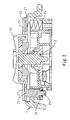
- the buffering protective handheld controller in the present invention is mainly to provide a buffering protective configuration for a directional button 2 and a number of functional buttons 3 on one side of the main unit 1.
- the surface of the directional button 2 is covered by an elastic ring 22, which is a layer of soft protective pad 23. Further, the bottom of the elastic ring 22 is held by a number of buffering devices 24.
- the buffering devices 24 can be flexible rubber, spring ... etc. to reduce holding pressure (a spring in the Figure).
- a number of moulded axles 25 at the bottom connect with an elastic pad 26.
- the elastic ring 22 is allowed to move around the top of a slot 27 and avoids jumping off the main unit 1.
- the user can acquire better comfortability by direct hand pressing on the protective pad 21 that covers the directional button 2. Especially, before the user's hand presses the directional button 2 to the bottom, it feels the touch on the protective pad 23 on the elastic ring 22 around the directional buttons 2. This not only provides a greater touch area but also pressure reduction by a multiple sets of buffering devices 24 at the bottom of the elastic ring 22 and cushion action on a number of axles 25 and washers 26. In this way, the user is under a multiple protection from top to bottom, which includes the protective pad 21 on top of the directional button 2, the elastic ring 22 moving around in the middle to reduce pressure, and bottom cushion composed of buffering devices 24, axles 25 and washers 26.
- Such a handheld controller not only has the most comfortability but also reduced holding pressure.
- the invention can provide fatigue reduction, blistering prevention and benefits like finger protection from callus and deformation.
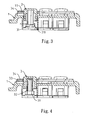
- the multiple number of functional buttons 3 have a buffering device, which can be an elastic silicone bushing 31 (as shown in Figure 3).
- a through-hole 311 of a height h is to incorporate the functional button 3.
- the buffering device can be a hollow silicone elastic pin 32 (as shown in Figure 4), which connects to the bottom of functional buttons 3 against the bushing 31.
- the elastic pin 32 enhances the pressure reduction for the functional buttons 3.
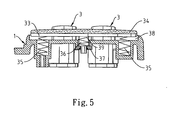
- the elastic ring 33 is held by a multiple number of buffering devices 35, which can be soft rubber, spring ... etc. to alleviate the pressure (spring in the Figure).
- a multiple sets of moulded axles 36 at its bottom all connect to an elastic washer 37 and are covered by a spring 39, so the elastic ring 33 can float around the top of the slot 38 and avoid jumping off the main unit 1.
- the buffering device at the bottom of the functional button 3 can provide comfort operatibility by reducing the pressure on user's hands.
- the touch action is on the protective pad 34 of the top of the elastic ring 33 around the functional button 3. It not only enlarges the touch area but also reduces pressure by the multiple number of buffering devices 35 at the bottom of the elastic ring 33 and the pressure reduction mechanism through a number of axles 36 and washers 37.
- the user is under a multiple protection from top to bottom, which includes the buffering device at the bottom of the functional button 3, the elastic ring 33 moving around in the middle to reduce pressure, and bottom cushion composed of buffering devices 35, axles 36 and washers 37.
- the invention that reduces the button holding pressure can provide fatigue reduction, blistering prevention and benefits like finger protection from callus and deformation.
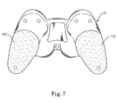
- the handheld portion of the base 11 of the main unit 1 in the invention is in a proper design of a hollow hole 111, which may be enclosed by a sticking soft pad 112 with a proper size.
- a cushion air-bag function to fit the user's palm in any shape and any size.
- the grasping force is greatly minimized during use.
- Such a handheld controller not only has the most comfortability but also reduced holding pressure.
- the buffering protective handheld controller provided in the present invention is mainly a unit with a buffering protective configuration for direction button and a number of functional buttons on one side of the main unit.
- the user is allowed to have greater touch area and more comfortability when pressing the button.
- the user has finger contact with surrounding buffering devices to reduce pressure.
- the handheld main unit has the rigid plastic base in an appropriate hollow shape, which may be enclosed by a sticking soft pad with a proper size.
- the handheld main unit has the rigid plastic base in an appropriate hollow shape, which may be enclosed by a sticking soft pad with a proper size.
- it can provide a cushion air-bag function and fits the user's palm in any shape and any size.
- the grasping force is minimized during use.
- Such a handheld controller not only has the most comfortability but also reduced holding pressure. Therefore, the invention can provide fatigue reduction, blistering prevention and benefits like finger protection from callus and deformation. This invention is considered to have great industrial applicability and progressiveness.
Landscapes
- Physics & Mathematics (AREA)
- General Physics & Mathematics (AREA)
- Engineering & Computer Science (AREA)
- Automation & Control Theory (AREA)
- Professional, Industrial, Or Sporting Protective Garments (AREA)
- Switches With Compound Operations (AREA)
- Mechanical Control Devices (AREA)
- Mattresses And Other Support Structures For Chairs And Beds (AREA)
Claims (4)
- Handsteuergerät, umfassend eine richtungsgebende Taste (2) und eine Anzahl von Funktionstasten (3) auf einer Seite der Haupteinheit (1); wobei die Oberfläche der Richttaste (2) mit einem weichen Schutzkissen (21) bedeckt ist, dadurch gekennzeichnet, dass:- die Richttaste (2) durch einen schwebenden Ring (22) umgeben ist, welcher mit einer Schicht aus weicher Schutzmatte (23) eingeschlossen ist; wobei der Boden des schwebenden Ringes (22) durch eine Vielzahl von Puffervorrichtungen (24) gehalten wird; wobei die Puffervorrichtungen (24) gegossene Mehrfachachsen (25) umfassen, die alle mit elastischen Beilagscheiben oder Kissen (26) an der Unterseite verbunden sind, so dass der schwebende Ring (22) um die Oberseite eines Schlitzes (27) innerhalb der Haupteinheit (1) herumschweben kann und es vermeidet von der Haupteinheit (1) abzuspringen;- die Funktionstasten (3) erste Puffervorrichtungen (31) umfassen und durch einen schwebenden Ring (33) umgeben sind, dessen Oberfläche durch ein weiches Schutzkissen (34) bedeckt ist und durch eine Vielzahl von zweiten Puffervorrichtungen (35) an der Unterseite gehalten wird, wobei die zweiten Puffervorrichtungen (35) eine Anzahl von gegossene Achsen (36) umfassen, die mit elastischen Beilagscheiben (37) verbunden sind, so dass der schwebende Ring darauf beschränkt ist, um die Oberseite eines Schlitzes (38) innerhalb der Haupteinheit (1) herumzuschweben, und es vermeidet von der Haupteinheit (1) abzuspringen;- der steife Kunststoffhandabschnitt der Haupteinheitsschale (11) von hohler Gestalt ist, welche durch ein klebendes weiches Kissen (112) eingeschlossen ist.
- Handsteuergerät gemäß Anspruch 1, dadurch gekennzeichnet, dass die Puffervorrichtungen an der Unterseite der Funktionstasten (3) elastische Silikonbuchsringe (31) mit einem Durchgangsloch (311) auf einer bestimmten Höhe auf ihrer Oberseite sein können, um jeweils die Funktionstaste (3) aufzunehmen.
- Handsteuergerät gemäß Anspruch 2, dadurch gekennzeichnet, dass sich auf der Unterseite der Funktionstaste (3) ein hohler elastischer Silikonstift (32) befindet, um den Boden des Buchsrings (31) zu halten.
- Handsteuergerät gemäß Anspruch 1, dadurch gekennzeichnet, dass die Puffervorrichtungen (24, 35) aus jeder Druck verringernden Vorrichtung wie weicher Gummi oder eine Feder sein können.
Priority Applications (3)
| Application Number | Priority Date | Filing Date | Title |
|---|---|---|---|
| EP20040001665 EP1560238B1 (de) | 2004-01-27 | 2004-01-27 | Stossabsorbierende tragbare Steuerungseinrichtung |
| DE602004004999T DE602004004999T2 (de) | 2004-01-27 | 2004-01-27 | Stossabsorbierende tragbare Steuerungseinrichtung |
| ES04001665T ES2282740T3 (es) | 2004-01-27 | 2004-01-27 | Controlador portatil protector por amortiguacion. |
Applications Claiming Priority (1)
| Application Number | Priority Date | Filing Date | Title |
|---|---|---|---|
| EP20040001665 EP1560238B1 (de) | 2004-01-27 | 2004-01-27 | Stossabsorbierende tragbare Steuerungseinrichtung |
Publications (2)
| Publication Number | Publication Date |
|---|---|
| EP1560238A1 EP1560238A1 (de) | 2005-08-03 |
| EP1560238B1 true EP1560238B1 (de) | 2007-02-28 |
Family
ID=34639378
Family Applications (1)
| Application Number | Title | Priority Date | Filing Date |
|---|---|---|---|
| EP20040001665 Expired - Lifetime EP1560238B1 (de) | 2004-01-27 | 2004-01-27 | Stossabsorbierende tragbare Steuerungseinrichtung |
Country Status (3)
| Country | Link |
|---|---|
| EP (1) | EP1560238B1 (de) |
| DE (1) | DE602004004999T2 (de) |
| ES (1) | ES2282740T3 (de) |
Families Citing this family (1)
| Publication number | Priority date | Publication date | Assignee | Title |
|---|---|---|---|---|
| CN104383682B (zh) * | 2014-11-24 | 2017-05-10 | 青岛歌尔声学科技有限公司 | 一种游戏手柄 |
Family Cites Families (5)
| Publication number | Priority date | Publication date | Assignee | Title |
|---|---|---|---|---|
| DE3742711A1 (de) * | 1987-12-16 | 1989-07-06 | Sasse Eugen Bauelemente | Tastschalter oder tastenfeld |
| JPH1190042A (ja) * | 1997-09-22 | 1999-04-06 | Sony Computer Entertainment Inc | ゲーム機用操作装置 |
| AU2508000A (en) * | 1999-01-15 | 2000-08-01 | Douglas J. Rudisch | Shock-absorbing keyboard and method |
| JP2001135198A (ja) * | 1999-11-01 | 2001-05-18 | Sony Computer Entertainment Inc | エンタテインメントシステムの操作装置及びこの操作装置を有するエンタテインメントシステム |
| FR2823001A1 (fr) * | 2001-03-30 | 2002-10-04 | Pierre Busquet | Coussinet amortisseur pour manettes de consoles de jeux video |
-
2004
- 2004-01-27 EP EP20040001665 patent/EP1560238B1/de not_active Expired - Lifetime
- 2004-01-27 ES ES04001665T patent/ES2282740T3/es not_active Expired - Lifetime
- 2004-01-27 DE DE602004004999T patent/DE602004004999T2/de not_active Expired - Lifetime
Also Published As
| Publication number | Publication date |
|---|---|
| EP1560238A1 (de) | 2005-08-03 |
| DE602004004999D1 (de) | 2007-04-12 |
| DE602004004999T2 (de) | 2007-11-22 |
| ES2282740T3 (es) | 2007-10-16 |
Similar Documents
| Publication | Publication Date | Title |
|---|---|---|
| US6998548B2 (en) | Buffering protective handheld controller | |
| US11806613B2 (en) | Controller for video game console | |
| US10799790B2 (en) | Paddle accessory for a game controller | |
| US10835812B2 (en) | Game controller with removable paddle accessory | |
| US6016138A (en) | Gel mouse | |
| US6545665B2 (en) | Adjustable computer pointing device | |
| US6587090B1 (en) | Finger securable computer input device | |
| US7167159B2 (en) | Joystick cover | |
| WO2010135287A2 (en) | Device for enhancing operation of a game controller and method of using the same | |
| WO2007054094A1 (en) | Electric hand control, especially for electrically adjustable hospital and care beds | |
| US7006075B1 (en) | Ergonomic computer mouse | |
| US7271354B2 (en) | Buffering protective handheld controller device | |
| EP1560238B1 (de) | Stossabsorbierende tragbare Steuerungseinrichtung | |
| US20040233169A1 (en) | Computer mouse | |
| US20060152490A1 (en) | Casing structure of mouse | |
| US5966118A (en) | Ergonomic computer mouse | |
| CN2684246Y (zh) | 具缓冲保护的手持摇杆 | |
| CN2715209Y (zh) | 缓冲保护手持摇杆装置 | |
| JP3102907U (ja) | 緩衝機能付きゲーム機コントローラー | |
| US20060187206A1 (en) | Computer mouse | |
| KR200260281Y1 (ko) | 컴퓨터 마우스용 보조장갑 | |
| JP7695701B2 (ja) | ストッパー具及びカバー体 | |
| KR100304495B1 (ko) | 컴퓨터용 마우스 | |
| JP6837041B2 (ja) | 半球マウス。 | |
| KR200492309Y1 (ko) | 받침부가 구비된 키보드 |
Legal Events
| Date | Code | Title | Description |
|---|---|---|---|
| PUAI | Public reference made under article 153(3) epc to a published international application that has entered the european phase |
Free format text: ORIGINAL CODE: 0009012 |
|
| AK | Designated contracting states |
Kind code of ref document: A1 Designated state(s): AT BE BG CH CY CZ DE DK EE ES FI FR GB GR HU IE IT LI LU MC NL PT RO SE SI SK TR |
|
| AX | Request for extension of the european patent |
Extension state: AL LT LV MK |
|
| 17P | Request for examination filed |
Effective date: 20060111 |
|
| AKX | Designation fees paid |
Designated state(s): DE ES FR GB IT NL |
|
| GRAP | Despatch of communication of intention to grant a patent |
Free format text: ORIGINAL CODE: EPIDOSNIGR1 |
|
| GRAS | Grant fee paid |
Free format text: ORIGINAL CODE: EPIDOSNIGR3 |
|
| GRAA | (expected) grant |
Free format text: ORIGINAL CODE: 0009210 |
|
| AK | Designated contracting states |
Kind code of ref document: B1 Designated state(s): DE ES FR GB IT NL |
|
| REG | Reference to a national code |
Ref country code: GB Ref legal event code: FG4D |
|
| REF | Corresponds to: |
Ref document number: 602004004999 Country of ref document: DE Date of ref document: 20070412 Kind code of ref document: P |
|
| ET | Fr: translation filed | ||
| REG | Reference to a national code |
Ref country code: ES Ref legal event code: FG2A Ref document number: 2282740 Country of ref document: ES Kind code of ref document: T3 |
|
| PLBE | No opposition filed within time limit |
Free format text: ORIGINAL CODE: 0009261 |
|
| STAA | Information on the status of an ep patent application or granted ep patent |
Free format text: STATUS: NO OPPOSITION FILED WITHIN TIME LIMIT |
|
| 26N | No opposition filed |
Effective date: 20071129 |
|
| PGFP | Annual fee paid to national office [announced via postgrant information from national office to epo] |
Ref country code: ES Payment date: 20090126 Year of fee payment: 6 |
|
| PGFP | Annual fee paid to national office [announced via postgrant information from national office to epo] |
Ref country code: NL Payment date: 20090122 Year of fee payment: 6 |
|
| PGFP | Annual fee paid to national office [announced via postgrant information from national office to epo] |
Ref country code: GB Payment date: 20090123 Year of fee payment: 6 |
|
| PGFP | Annual fee paid to national office [announced via postgrant information from national office to epo] |
Ref country code: IT Payment date: 20090126 Year of fee payment: 6 |
|
| PGFP | Annual fee paid to national office [announced via postgrant information from national office to epo] |
Ref country code: FR Payment date: 20090120 Year of fee payment: 6 |
|
| REG | Reference to a national code |
Ref country code: NL Ref legal event code: V1 Effective date: 20100801 |
|
| GBPC | Gb: european patent ceased through non-payment of renewal fee |
Effective date: 20100127 |
|
| REG | Reference to a national code |
Ref country code: FR Ref legal event code: ST Effective date: 20100930 |
|
| PG25 | Lapsed in a contracting state [announced via postgrant information from national office to epo] |
Ref country code: NL Free format text: LAPSE BECAUSE OF NON-PAYMENT OF DUE FEES Effective date: 20100801 Ref country code: FR Free format text: LAPSE BECAUSE OF NON-PAYMENT OF DUE FEES Effective date: 20100201 |
|
| PG25 | Lapsed in a contracting state [announced via postgrant information from national office to epo] |
Ref country code: GB Free format text: LAPSE BECAUSE OF NON-PAYMENT OF DUE FEES Effective date: 20100127 |
|
| REG | Reference to a national code |
Ref country code: ES Ref legal event code: FD2A Effective date: 20110328 |
|
| PG25 | Lapsed in a contracting state [announced via postgrant information from national office to epo] |
Ref country code: IT Free format text: LAPSE BECAUSE OF NON-PAYMENT OF DUE FEES Effective date: 20100127 |
|
| PG25 | Lapsed in a contracting state [announced via postgrant information from national office to epo] |
Ref country code: ES Free format text: LAPSE BECAUSE OF NON-PAYMENT OF DUE FEES Effective date: 20110315 |
|
| PG25 | Lapsed in a contracting state [announced via postgrant information from national office to epo] |
Ref country code: ES Free format text: LAPSE BECAUSE OF NON-PAYMENT OF DUE FEES Effective date: 20100128 |
|
| PGFP | Annual fee paid to national office [announced via postgrant information from national office to epo] |
Ref country code: DE Payment date: 20120330 Year of fee payment: 9 |
|
| PG25 | Lapsed in a contracting state [announced via postgrant information from national office to epo] |
Ref country code: DE Free format text: LAPSE BECAUSE OF NON-PAYMENT OF DUE FEES Effective date: 20130801 |
|
| REG | Reference to a national code |
Ref country code: DE Ref legal event code: R119 Ref document number: 602004004999 Country of ref document: DE Effective date: 20130801 |