EP1560096A2 - Geländefolgeverfahren - Google Patents
Geländefolgeverfahren Download PDFInfo
- Publication number
- EP1560096A2 EP1560096A2 EP05250190A EP05250190A EP1560096A2 EP 1560096 A2 EP1560096 A2 EP 1560096A2 EP 05250190 A EP05250190 A EP 05250190A EP 05250190 A EP05250190 A EP 05250190A EP 1560096 A2 EP1560096 A2 EP 1560096A2
- Authority
- EP
- European Patent Office
- Prior art keywords
- air vehicle
- profile
- terrain
- envelope
- flight
- Prior art date
- Legal status (The legal status is an assumption and is not a legal conclusion. Google has not performed a legal analysis and makes no representation as to the accuracy of the status listed.)
- Withdrawn
Links
Images


Classifications
-
- G—PHYSICS
- G05—CONTROLLING; REGULATING
- G05D—SYSTEMS FOR CONTROLLING OR REGULATING NON-ELECTRIC VARIABLES
- G05D1/00—Control of position, course, altitude or attitude of land, water, air or space vehicles, e.g. using automatic pilots
- G05D1/04—Control of altitude or depth
- G05D1/06—Rate of change of altitude or depth
- G05D1/0607—Rate of change of altitude or depth specially adapted for aircraft
- G05D1/0646—Rate of change of altitude or depth specially adapted for aircraft to follow the profile of undulating ground
Definitions
- the present invention relates to terrain following and, more particularly, to real-time methods for designing a terrain-following flight profile.
- a combat air vehicle for example a bomber, must fly close to the ground in order to reach its target without being detected and intercepted by the enemy.
- the general problem of flying as close as possible to the ground along a given flight path is known as the "terrain-following" problem.
- Early terrain following systems used active on-board sensors to determine the aircraft's position and terrain clearance. Radiation emitted by such active sensors could be detected by the enemy.
- Alson C. Woodward and Wayne M. Hoover (“Passive terrain following using stored map and global positioning system", IEEE NAECON 0547-3578/81/0000-0079) recognized that an aircraft with an on-board GPS receiver could follow a pre-stored reference terrain profile while using the GPS receiver to measure its own position.
- the aircraft actually follows a pre-stored reference flight profile that corresponds to the terrain profile.
- the design of the flight profile is an optimization problem: within the constraints of the aircraft's performance limitations, how close can the aircraft fly to the ground while following the flight path? See, for example, Ping Lu and Bion L. Pierson, "Optimal aircraft terrain-following analysis and trajectory generation", Journal of Guidance, Control and Dynamics vol. 18 no. 3, May-June 1995. Usually, this optimization problem is solved iteratively.
- the present invention relates to terrain-following guidance of an air vehicle.
- air vehicle is understood herein to include any vehicle capable of flight, including in particular manned aircraft and unmanned aerial vehicles (UAVs).
- UAVs unmanned aerial vehicles
- the trajectory followed by an air vehicle is a line in three-dimensional ( x, y, z ) space.
- the flight path of the air vehicle is a projection of the trajectory onto a horizontal ( x, y ) plane.
- the flight profile of the air vehicle is the vertical ( z ) coordinate of the trajectory as a function of distance s along the flight path.
- the problem of optimal design of the trajectory as a whole is the terrain avoidance problem. This problem is more general than and beyond the scope of the present invention, although the present invention could be used as a component of the solution of the terrain avoidance problem. As discussed above, the problem addressed by the present invention is the terrain following problem: given an a priori flight path, what is the optimal flight profile?
- a terrain profile is an estimate of the ground elevation as a function of s along the flight path.
- the flight profile is designed with reference to the corresponding terrain profile.
- the terrain profile is inflated to provide a safety margin.
- the present invention is directed towards methods of transforming a terrain profile into a flight profile. That the flight profile is a terrain-following flight profile means that the flight profile is designed to parallel the terrain as closely as possible within the relevant constraints.
- the terrain profile that is transformed to the desired flight profile is defined with reference to a given flight path. More generally, to allow a manned air vehicle freedom of horizontal maneuver around the given flight path, the terrain profile is defined, with reference to a flight corridor of a given finite horizontal width about the flight path, as an estimate, as a function of s , of the maximum ground elevation along and to the sides of the flight path.
- the process of inflating the terrain profile takes into account the uncertainty in the lateral displacement of the air vehicle from the nominal flight path. Note that a flight path can be viewed as a special case of a flight corridor, to wit, a flight corridor of infinitesimal width.
- an envelope of the function is a function g ( s ) that is equal to f ( s ) at selected points s and otherwise is greater than f ( s ).
- the filtered terrain profile is an envelope of the inflated terrain profile and the flight profile is constructed by constructing successive envelopes of the filtered terrain profile.
- the present invention provides a direct, non-iterative method of terrain-following flight profile design that is fast enough to be implemented in real time and so to be based on actual navigational uncertainties and on instantaneous values of air vehicle performance parameters rather than on worst case navigational uncertainties and on worst case values of air vehicle performance parameters. Because the present invention operates in real time, the present invention can take into account the changes in the performance characteristics of the air vehicle as the air vehicle flies along the trajectory whose altitude is defined by the flight profile.
- the computations of the present invention do not require the fitting of a functional approximation to a discrete digital terrain map.
- the present invention allows a tradeoff, in flight profile design, between the closeness with which the air vehicle follows the terrain and the gentleness of the maneuvers executed by the air vehicle.
- a method of designing a terrain-following flight profile for an air vehicle including the steps of: (a) providing a terrain profile; and (b) transforming the terrain profile into the terrain-following flight profile in accordance with at least one performance parameter of the air vehicle.
- a method of designing a terrain-following flight profile for an air vehicle including the steps of: (a) defining a terrain profile with reference to a flight corridor; (b) inflating the terrain profile, thereby providing an inflated terrain profile; (c) filtering the inflated terrain profile, thereby providing a filtered terrain profile; (d) constructing a first envelope for the filtered terrain profile, the first envelope being constrained so that every positive slope of the first envelope is at most about as great as a maximum climb slope of the air vehicle and every negative slope of the first envelope is at most about as small as a minimum dive slope of the air vehicle; (e) constructing a second envelope for the first envelope, the second envelope being constrained so that if the air vehicle flies at a given speed according to the second envelope, every negative vertical acceleration of the air vehicle is at most about as small as a minimum negative vertical acceleration of the air vehicle; and (f) constructing a third envelope for the second envelope, the third envelope being constrained so that if the air vehicle
- a method of designing a terrain-following flight profile for an air vehicle including the steps of: for each of a plurality of frames: (a) providing a respective terrain profile; and (b) transforming the respective terrain profile into at least a portion of the terrain-following flight profile in accordance with at least one performance parameter of the air vehicle.
- a method of designing a terrain-following flight profile for an air vehicle including the steps of: (a) providing a terrain profile; and (b) filtering the terrain profile by steps including: (i) selecting a filter length, and (ii) constructing an envelope of the terrain profile in accordance with the filter length, the terrain-following flight profile then being based on the envelope.
- a method of navigating an air vehicle within a flight corridor including the steps of: (a) partitioning the flight corridor among a set of at least one frame; and (b) as the air vehicle enters each of the at least one frame: (i) defining a respective terrain profile with respect to a respective portion of the flight corridor that lies within the each frame, and (ii) transforming the respective terrain profile into a respective flight profile for the each frame in accordance with at least one performance parameter of the air vehicle.
- an air vehicle including: (a) a memory for storing a map; (b) a processor for: (i) partitioning a flight corridor among a set of at least one frame, and (ii) as the air vehicle enters each of the at least one frame: (A) based on the map, providing a respective terrain profile for a respective portion of the flight corridor that lies within the each frame, and (B) transforming the respective terrain profile into a respective terrain-following flight profile for the each frame in accordance with at least one performance parameter of the air vehicle; and (c) a propulsion and guidance system for flying the air vehicle within the flight corridor in accordance with the at least one respective flight profile.
- a method of designing a terrain-following flight path for an air vehicle including the steps of: (a) providing a terrain profile; and (b) transforming the terrain profile into the terrain-following flight path in accordance with a desired tradeoff between a closeness with which the terrain-following flight path tracks the terrain profile and an ease of maneuver of the air vehicle.
- the present invention has two principle aspects.
- the first aspect is the non-iterative transformation of a terrain profile into a terrain-following flight profile, in accordance with one or more air vehicle performance parameters.
- the second aspect is low-pass spatial filtering of the terrain profile prior to the construction of the flight profile.
- the terrain profile is defined with reference to a flight corridor.
- the first aspect of the present invention can be viewed as a method of navigating the air vehicle within a given flight corridor.
- the "flight corridor" is actually a flight path.
- the terrain profile is transformed into the flight profile in a manner that directly adapts the terrain profile to the performance parameters of the air vehicle.
- This is in contrast to prior art methods that obtain a flight profile by fitting functions such as polynomials to the terrain profile.
- the difference between the direct adaptation of the present invention and the indirect adaptation of those prior art methods can be appreciated by considering what kind of flight profile is produced from a flat or gently varying terrain profile.
- the prior art methods produce a flight profile whose shape reflects both the shape of the terrain profile and the shapes of the functions that are fitted to the terrain profile.
- the method of the present invention produces a flight profile that is exactly parallel to the terrain profile.
- the flight profile is constructed as an envelope of the terrain profile that is constrained in accordance with at least one performance parameter of the air vehicle.
- four performance parameters are accounted for: a maximum allowed climb slope, a minimum allowed dive slope, a minimum allowed negative vertical acceleration as the air vehicle flies at a given speed, and a maximum allowed positive vertical acceleration as the air vehicle flies at the given speed.
- the flight profile is constructed in three steps. In the first step, a first envelope of the terrain profile is constructed subject to the constraints that every positive slope of the first envelope is at most about as great as the maximum allowed climb slope and that every negative slope of the first envelope is at most about as small as the minimum allowed dive slope.
- a second envelope is constructed as an envelope of the first envelope, subject to the same constraints as the first envelope, and also to the constraint that if the air vehicle were to fly at the given speed according to the second envelope as the flight profile, every negative vertical acceleration of the air vehicle would be at most about as small as the minimum allowed negative vertical acceleration.
- a third envelope is constructed as an envelope of the second envelope, subject to the same constraints as the first envelope and also to the constraint that if the air vehicle were to fly at the given speed according to the third envelope as the flight profile, every positive vertical acceleration of the air vehicle would be at most about as great as the maximum allowed positive vertical acceleration.
- the third envelope is the desired flight profile.
- the flight profile is constructed in real time, in the sense that the flight profile is constructed while the air vehicle flies along a flight path corresponding to at least a portion of the terrain profile.
- the terrain profile is an inflated terrain profile.
- the terrain profile is filtered prior to the construction of the flight profile, also in real time, in the sense that the filtering is done while the air vehicle flies along a flight path corresponding to at least a portion of the terrain profile.
- the preferred filtering method is itself an independent aspect of the present invention.
- a filter length is selected, and an envelope of the terrain profile is constructed in accordance with the filter length and is substituted for the terrain profile in the construction of the flight profile.
- this envelope is piecewise linear. More preferably, this envelope is constructed by selecting a plurality of points of the terrain profile and connecting neighboring pairs of points with straight line segments.
- the points are selected, starting with a first point of the terrain profile as a pivot point, by downwardly pivoting a filtering line segment, whose horizontal extent is equal to the filter length, _about the pivot point until the filtering line segment contacts the terrain profile, selecting the last point at which the filtering line segment contacts the terrain profile, moving the pivot point to the last point at which the filtering line segment contacts the terrain profile, and repeating the process until the last point at which the filtering line segment contacts the terrain profile is the last point of the terrain profile.
- the two aspects of the present invention can be considered to be stages in the transformation of a terrain profile into a terrain-following flight path in accordance with a desired tradeoff between the closeness with which the flight path tracks the terrain profile and the ease of maneuver of the air vehicle as the air vehicle attempts to fly according to the flight path.
- the filter length of the second aspect preferably is selected in accordance with the desired tradeoff
- the flight path is partitioned among a plurality of frames, a respective terrain profile is provided for each frame as the air vehicle enters the frame, and a corresponding respective flight profile is constructed as described above for each frame.
- the overall flight profile then is a concatenation of the individual respective flight profiles.
- the frames overlap, and this "concatenation" actually is a concatenation of the initial portions of the individual respective flight profiles, until the last frame is reached, at which point the entire respective flight profile of the last frame is concatenated to the overall composite flight profile.
- the air vehicle then is flown in accordance with the concatenated flight profile.
- the providing of the respective terrain profile of each frame is done by providing a digital terrain map that includes a plurality of elevations and then, at each of a plurality of points along a nominal flight path within the frame, determining a maximum elevation within an uncertainty interval around that point.
- the resulting set of maximum elevations, as a function of the points along the nominal flight path, is the desired terrain profile.
- An air vehicle of the present invention includes an on-board memory, an on-board processor, and a propulsion and guidance system.
- the memory is used to store a map.
- the processor partitions the flight path among a set of frames. As the air vehicle enters each frame, the processor provides a respective terrain profile for the respective portion of a flight corridor that lies within the frame. This terrain profile is based on the map that is stored in the memory. Then the processor transforms the respective terrain profile into a respective flight profile for the frame in accordance with at least one performance parameter of the air vehicle.
- the propulsion and guidance system then is used to fly the air vehicle along the flight path in accordance with the flight profile until the next frame is reached.
- the map is a digital terrain map.
- each flight profile is a terrain-following flight profile.
- the "flight corridor" is actually a flight path.
- the present invention is of a method of designing a terrain-following flight profile.
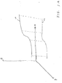
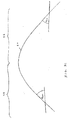
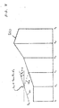
- Figure 1A shows a trajectory 10 of an air vehicle flying in a three-dimensional space defined by Cartesian coordinates x, y and z.
- z is the altitude coordinate.
- x and y are geographic coordinates, for example north and east as in the Universal Transverse Mercator grid. Note that this coordinate system is a left-handed coordinate system.
- the corresponding flight path 12 is the projection of trajectory 10 onto the x , y plane.
- Figure 1B shows the corresponding flight profile 14: the z - coordinate of trajectory 10 as a function of horizontal distance s along flight path 12 .
- the air vehicle flies in the direction of increasing s , which in the relevant Figures is from left to right.
- the various profiles (terrain profiles, flight profile) considered herein are sampled at discrete sample points s i along flight path 12.
- these sample points usually are assumed to be a constant interval ds apart. It will be clear to those ordinarily skilled in the art how to modify the subsequent discussion to account for irregular sampling of the distance coordinate s .
- Figure 1B also shows that flight path 12 is partitioned among a set of overlapping frames F 1 through F N .
- the air vehicle flies along flight path 12, the air vehicle first enters frame F 1 , then frame F 2 , etc.
- the air vehicle is considered to be flying in the local frame with the highest index. So, for example, after the air vehicle enters frame F 2 , the air vehicle is considered to be flying in frame F 2 even though the s -coordinate of the air vehicle is still within frame F 1 .
- the interval between the left end of a frame and the left end of the next frame is a constant distance ⁇ s along flight path 12.
- the interval between the left end of every frame (other than the last frame) and the left end of the next frame is chosen so that the air vehicle spends the same time interval ⁇ t flying from the left end of one frame to the left end of the next frame.
- ⁇ s is selected in accordance with factors that include terrain complexity, the computational power available to the air vehicle, the rate of increase of navigational uncertainty and the frequency of navigational updates.
- all the frames except for the frames at the end of flight path 12 are given a common length chosen in advance in accordance with regional terrain roughness.
- the problem addressed herein is the terrain-following problem: given a terrain profile, i . e ., an estimate of terrain altitude along flight path 12, design a trajectory 10 for an air vehicle to fly as close as is feasible to the terrain along flight path 12. Because flight path 12 is given in advance (and indeed is fixed a priori if the air vehicle is unmanned), this is equivalent to designing a flight profile 14 for the air vehicle.
- Flight path 12 is a reference flight path, i.e., a nominal flight path that the air vehicle attempts to follow. Because of navigational uncertainties and similar sources of error, the actual flight path followed by the air vehicle, i . e ., the projection to a horizontal plane of the actual trajectory flown by the air vehicle, only approximates the reference flight path.
- the flight profile provided to the air vehicle by the present invention is a reference flight profile that is only approximated by the altitude coordinate of the actual trajectory flown by the air vehicle.
- the present invention provides the air vehicle with a reference flight profile that is adapted in real time to the contingencies of flight. This is accomplished in three phases: terrain profile inflation, terrain profile filtering and flight profile shaping. For each frame, all three phases are effected as soon as the air vehicle enters the frame, to provide a reference flight profile that the air vehicle attempts to follow until the air vehicle enters the next frame.
- the input to this phase is the reference flight path, a digital terrain map of the region that includes the reference flight path, and, for a manned air vehicle, the width of the allowed flight corridor to the sides of the reference flight path. If it could be guaranteed that both the altitude and the geographical coordinates of the air vehicle were always known with perfect accuracy, and that the digital terrain map was perfectly accurate, then the terrain altitude along the reference flight path could be used as the terrain profile that is input to the second and third phases. Because neither the altitude of the air vehicle nor the geographic coordinates of the air vehicle nor the terrain altitude are known with perfect accuracy, this nominal terrain profile must be "inflated" to guarantee that the air vehicle does not hit the ground.
- the inflated terrain profile is constructed in two steps.
- the first step accounts for errors in lateral position.
- the second step accounts for altitude errors.
- a horizontal corridor is defined along the reference flight path.
- the width of the horizontal corridor is the root-mean-square sum of all the errors that contribute to the lateral positional uncertainty of the air vehicle, plus, in the case of a manned air vehicle, the width of the allowed flight corridor.
- the digital terrain map is sampled in a region (usually a rectangular or elliptical region) centered on at that point s . The maximum value of the digital terrain map within this region is taken as the terrain altitude at point s .
- the root-mean-square sum of all the errors that contribute to the vertical positional uncertainty of the air vehicle, is added to the terrain altitude from the first step.
- the resulting terrain profile is the "inflated" terrain profile that is input to the second phase.
- the terrain profile is inflated in real time to exploit the following feature of air vehicle navigation.
- the contribution of navigational uncertainty to the width of the horizontal corridor of the first step tends to grow with time. Therefore, the width of the horizontal corridor of the first step also tends to grow with time.
- the air vehicle receives a relatively accurate navigational update that reduces the lateral navigational uncertainty of the air vehicle.
- the air vehicle may use, for navigation, an on-board self-contained navigational instrument such as an inertial measurement unit, supplemented by occasional updates from a navigational instrument such as a GPS receiver that relies on external signals.
- the width of the horizontal corridor shrinks accordingly, as does the range of digital terrain map altitudes that contributes to the calculation of maximum terrain altitude at each point s in the first step.
- the inflation of the terrain profile becomes less severe, and the air vehicle is enabled to follow the terrain more closely than would have been possible without real-time inflation.
- the relatively accurate navigational update often indicates that the air vehicle is farther from the reference flight path than was indicated by the self-contained navigational instrument. When this occurs, the aircraft is flown so as to approach the reference flight path.
- the horizontal corridor also is modified to account for the deviation of the actual lateral position of the air vehicle from the reference flight path.
- phase I The input to this phase is the inflated terrain profile that is output by phase I.
- the purpose of this phase is to allow a tradeoff between close following of the terrain and ease of maneuver.
- the inflated terrain profile is filtered.
- the length of the filter determines the tradeoff, with a short filter favoring close following of the terrain and a long filter favoring ease of maneuver.
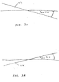
- Figure 2A illustrates the geometric construction that is used to transform an inflated terrain profile into a filtered terrain profile.
- Figure 2A shows a 2 km long segment 22 of an inflated terrain profile H(s) along with a filtering line segment 24.
- Filtering line segment 24 is constructed to have a horizontal extent equal to a preselected filter length, which in this example is 2 km.
- the left end of terrain profile segment 22 is used as a pivot point 26, at which the left end of filtering line segment 24 is attached.
- Filtering line segment 24 is pivoted downward about pivot point 26, as indicated by the arrow, while maintaining the 2 km horizontal extent of filtering line segment 24 at the preselected filter length, until filtering line segment 24 contacts terrain profile segment 22 to the right of pivot point 26 .
- filtering line segment 24 between pivot point 26 and the last point of contact 28 between terrain profile segment 22 and filtering line segment 24 then becomes a segment of a piecewise linear envelope of terrain profile H ( s ).
- filtering line segment 24 first contacts terrain profile segment 22 at only one point to the right of pivot point 26.
- Figure 2B shows a terrain profile segment 22' such that when filtering line segment 24 first contacts terrain profile segment 22' , this contact is at two points 30 and 32.
- the portion of filtering line segment 24 between pivot point 26 and the rightmost point of contact (point 32) is taken as the corresponding line segment of the piecewise linear envelope.
- Point 32 then becomes the next pivot point, for constructing the next line segment of the piecewise linear envelope.
- Figure 2C shows a terrain profile segment 22" that is similar to terrain profile segment 22' except that instead of point 32 , terrain profile segment 22" has a point 32' that is below filtering line segment 24 when filtering line segment 24 reaches point 30.
- the portion of filtering line segment 24 between pivot point 26 and the single point of contact (point 30 ) is taken as the corresponding line segment of the piecewise linear envelope; and point 30 then becomes the next pivot point.
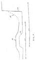
- solid line 40 is an inflated terrain profile H(s) of which terrain profile segment 22 is an initial portion.
- Dashed line segments 42, 44, 46, 48 and 50 are line segments of a piecewise linear envelope of terrain profile 40 , constructed as described above.
- Line segment 42 is constructed as described above in connection with Figure 2A.
- Line segment 44 is constructed by pivoting filtering line segment 24 downwards about point 28 as a pivot point until filtering line segment 24 contacts terrain profile 40 at point 34 .
- Line segment 46 is constructed by pivoting filtering line segment 24 downwards about point 34 as a pivot point until filtering line segment 24 lies tangent to terrain profile 40 between points 34 and 36 (line segment 46 is illustrated in Figure 2D as slightly displaced from terrain profile 40 , for clarity).
- Line segment 48 is constructed by pivoting filtering line segment 24 downwards about point 36 as a pivot point until filtering line segment 24 contacts terrain profile 40 at point 38.
- Line segment 50 is constructed by pivoting filtering line segment 24 downwards about point 38 until filtering line segment 24 contacts terrain profile 40 at a point (not shown) to the right of the portion of terrain profile 40 that is illustrated in Figure 2D.
- the piecewise linear envelope defined by line segments 42, 44, 46, 48, 50 and other line segments (not shown) to the right of the portion of terrain profile 40 that is illustrated in Figure 2D constitute a filtered terrain profile.
- the filtering algorithm Given a filter length L , is as follows:
- Terrain profile filtering is performed on a per-frame basis. To preserve continuity of the filtered terrain profile, upon entering a new frame, if the filtered terrain profile of the old frame is higher than the first point of the inflated terrain profile of the new frame (which first point otherwise would be used as the first pivot point of the new frame), the point at which the filtered terrain profile of the old frame enters the new frame is used as the first pivot point of the new frame.
- the input to this phase is the filtered terrain profile that is output by phase II.
- This phase consists of three subphases.
- an envelope of the input filtered terrain profile is constructed.
- respective envelopes of the envelopes from the immediately preceding subphases are constructed.
- the envelope constructed by the third subphase is the desired flight profile.
- the three envelopes are constructed to adapt the respective inputs to real time performance parameters of the air vehicle.
- the first subphase adapts the filtered terrain profile to the maximum climb angle ⁇ max and the minimum dive angle ⁇ min , or equivalently, to the maximum climb slope tan ⁇ max and the minimum dive slope tan ⁇ min of the air vehicle.
- the second subphase adapts the output of the first subphase to the horizontal velocity component V of the air vehicle in the current frame and to the minimum negative vertical acceleration a Zmin of the air vehicle, in a manner that guarantees that the air vehicle flies horizontally above significant local elevation peaks.
- the third subphase adapts the output of the second subphase to the horizontal velocity component V of the air vehicle in the current frame and to the maximum positive vertical acceleration a Zmax of the air vehicle.
- the three envelopes are constructed using the templates illustrated in Figures 3A-3D.
- the first subphase uses templates 52 and 54.
- Template 52 is a straight line with a slope tan ⁇ min .
- Template 54 is a straight line with a slope tan ⁇ max .
- the second subphase uses two templates 56 and 58 that are, respectively, the descending and ascending branches of a concave downward curve 60 .
- the central portion of curve 60 is the concave downward parabolic trajectory flown by the air vehicle as the horizontal component of the air vehicle's velocity is V and as the air vehicle accelerates downward with a constant vertical acceleration of a Zmin .
- the parabola continues rightward until the slope of the parabola reaches tan ⁇ min .
- the slope of the descending branch of curve 60 is a constant tan ⁇ min .
- the parabola continues leftward until the slope of the parabola reaches tan ⁇ max .
- the slope of the ascending branch of curve 60 is a constant tan ⁇ max .
- the third subphase uses a template 62 that is a concave upward curve.
- the central portion of template 62 is the concave upward parabolic trajectory flown by the air vehicle as the horizontal component of the air vehicle's velocity is V and as the air vehicle accelerates upward with a constant vertical acceleration of a Zmax .
- the parabola continues rightward until the slope of the parabola reaches tan ⁇ max .
- the slope of the ascending branch of template 62 is a constant tan ⁇ max .
- the parabola continues leftward until the slope of the parabola reaches tan ⁇ min .
- the slope of the descending branch of template 62 is a constant tan ⁇ min .
- the performance parameters to which the subphases adapt their respective envelopes often vary in time. For example, as an air vehicle consumes fuel and so becomes lighter, its maximum climb slope tan ⁇ max and its maximum positive vertical acceleration a Zmax may increase.
- the values of the performance parameters actually used to shape the flight profile of any given frame are the values of the performance parameters as the air vehicle enters the frame.
- the input filtered terrain profile and the various envelope functions are defined as a set of discrete elevations ⁇ h n ⁇ at discrete sampling points ⁇ s n ⁇ a fixed distance ds apart. It will be obvious to those skilled in the art how to generalize this discussion to irregularly spaced sample points and to other representations, for example piecewise continuous polynomial representations of higher order than first order, of the terrain profile and of the envelope functions.
- the input to the first pass is the filtered terrain profile.
- template 52 is swept across the filtered terrain profile in the direction of decreasing s (right to left), and whenever template 52 contacts the filtered terrain profile at two points, the portion of the filtered terrain profile between the two points is raised to match template 52 .
- the input to the second pass is the output of the first pass.
- template 54 is swept across the output from the first pass in the direction of increasing s (left to right), and whenever template 54 contacts the output from the first pass at two points, the portion of the output from the first pass that lies between the two points is raised to match template 54 .
- the algebraic algorithm of the second pass is similar to the algebraic algorithm of the first pass, but considers the slopes to the left of the sample points.
- Figure 4B shows the envelope 64' of filtered terrain profile 64 that was constructed in Figure 4A, with two elevations 70 and 72 such that the positive slopes immediately to the left of these elevations are greater than tan ⁇ max .
- the elevations immediately to the left of elevations 70 and 72 are replaced with the elevations marked by the triangles.
- the input to the first pass is the envelope derived in the first subphase.
- template 56 is swept across the envelope from the first subphase in the direction of decreasing s (right to left).
- template 56 is made tangent there to the envelope from the first subphase, and the portion of the envelope from the first subphase, that lies between the target value of s and the next intersection, to the right of the target value of s, of template 56 and the envelope of the first subphase, is raised to match template 56.
- no negative slopes of the envelope from the first subphase are more negative than tan ⁇ min .
- the second derivative of the envelope from the first subphase is used as a proxy for the curvature.
- the corresponding algebraic algorithm addresses the local second derivative h " with respect to s of the envelope from the first subphase.
- the numerical approximation that is used to calculate the second derivative at s n is h" n ⁇ ( h' n -h' n -1 )/ ds .
- the input to the second pass is the output of the first pass.
- template 58 is swept across the output of the first pass, in the direction of increasing s (left to right).
- template 58 is made tangent there to the output of the first pass and the portion of the output of the first pass that lies between the target value of s and the next intersection, to the left of the target value of s , of template 58 and the output of the first pass, is raised to match template 58.
- no positive slopes of the output of the first pass are more positive than tan ⁇ max .
- the second derivative of the output of the first pass is used as a proxy for the curvature.
- the corresponding algebraic algorithm also addresses the local second derivative h " with respect to s of the output of the first pass, but with a somewhat different condition for excessive downward curvature:
- the input to the third subphase is the envelope derived in the second subphase.
- template 62 is lowered as far as possible into the valleys of the envelope from the second subphase. Any valley in which template 62 contacts the two walls of the valley, instead of contacting the valley floor, has excessive upward curvature.
- the portion of the envelope from the second subphase that lies between the two contact points is raised to match template 62 .
- the corresponding algebraic algorithm addresses the local second derivative h " with respect to s of the envelope from the second subphase.
- the numerical approximation of the second subphase is used to calculate the second derivative at all sample points s n , from left to right.
- Figure 6 illustrates the geometric construction that is used to fit template 62 to the envelope from the second subphase.
- the envelope is a set of discrete points ⁇ ( s n , h n ) ⁇
- this construction is the "launch", towards the right of one of the points, of a continuous, piecewise linear approximation 100 of template 62 that is tangent to the envelope immediately to the left of a launch point 102.
- the slope of the envelope immediately to the left of launch point 102 is h' n -1
- the slope of segment 104 of approximation 100 that is tangent ta the envelope also is h' n -1 .
- the slope of the next segment 106 of approximation 100 then is h' n -1 +h" max ds , the slope of the segment immediately to the right of segment 106 is h' n -1 +2 h" max ds , and so on until the slope reaches tan ⁇ max .
- sample point s n For each sample point s n with an excessive second derivative, two such piecewise linear approximations of template 62 are launched from two adjacent points of the envelope from the second subphase.
- the first attempt to construct the piecewise linear approximations is made at sample points s n and s n -1 . Because sample point s n has an excessive second derivative, the piecewise linear approximation that is launched from sample point s n is guaranteed to be below the envelope from the second subphase, at least initially.
- the portion of this piecewise linear approximation between its launch point and its point of tangency defines the desired flight profile between those two points.
- the desired flight profile must lie somewhere between the "lower” piecewise linear approximation that is launched from sample point s n and the "upper” piecewise linear approximation that is launched from point s n -1 .
- a third polygonal approximation to template 62 is found that, having been launched from sample point s n -1 but with a slope intermediate between the first two piecewise linear approximations, is tangent to the envelope from the second subphase. The portion of the third polygonal approximation between its launch point and its point of tangency defines the desired flight profile between those two points.
- the construction is repeated for the pair of sample points ( s n -1 , s n -2 ), and so on, until a pair of sample points is found such that the piecewise linear approximation launched from the rightmost of the two sample points intersects the envelope from the second subphase and the piecewise linear approximation launched from the leftmost of the two sample points is tangent to or entirely above the envelope from the second subphase.
- the third polygonal approximation is found as follows, in the general case of the "upper" piecewise linear approximation emerging from the envelope from the second subphase at sample point s n-j and the "lower” piecewise linear approximation emerging from the envelope from the second subphase at sample point s n-j +1 .
- h ' h' L + ⁇ h /( s m -s n-j )
- h' L is the slope of the first segment of the "lower” piecewise linear approximation
- ⁇ h is the depth of the "lower piecewise linear approximation below the envelope from the second subphase at sample point s m .
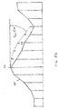
- Figure 7A shows an example of an envelope 84, from the second subphase, that has an excessive second derivative at a point 86 .
- a "lower” piecewise linear approximation 88 to template 62 is launched from the point 94 immediately to the left of point 86 and intersects envelope 84 to the right of point 86 .
- An "upper” piecewise linear approximation 90 to template 62 is launched from the point 96 immediately to the left of point 94 and lies entirely above envelope 84.
- a third piecewise linear approximation 92 to template 62 is found as described above that, having been launched from point 96, is tangent to envelope 84 at a point 98 to the right of point 94.
- Piecewise linear approximation 92 defines the desired flight profile between points 96 and 98 .
- Figure 7B shows a similar envelope 84', from the second subphase, in which piecewise linear approximation 88 to template 62 is tangent to envelope 84' at a point 98' .
- Piecewise linear approximation 88 defines the desired flight profile between points 94 and 98 . If piecewise linear approximation 88 were entirely above envelope 84' , then the procedure described above would be used to find a piecewise linear approximation to template 62 that is below piecewise linear approximation 88 , and that is tangent to envelope 84' , to serve as the desired flight profile between point 94 and the point of tangency.
- the flight profile must connect smoothly to the "normal" trajectory along which the air vehicle flies before entering the terrain-following flight profile and after exiting the terrain-following flight profile.
- the flight profile computed for one frame must connect smoothly to the flight profile of the next frame.
- the initial altitude h and flight angle ⁇ must be defined for all the frames, as must the final altitude h and flight angle ⁇ of the last several frames. Usually, this is done by replacing the first two elevations of the inflated and filtered terrain profile, at the beginning of each frame, with the elevations h 0 and h 0 +tan ⁇ 0 ds , respectively, where h 0 is the altitude of the previous flight profile upon entry to the frame (as defined by the normal trajectory upon entering the first frame, or by the flight profile of the previous frame upon entering one of the other frames) and ⁇ 0 is the corresponding flight profile angle; and by replacing the last two elevations of the inflated and filtered profile of the last several frames with the elevations h f -tan ⁇ f ds and h f , where h f is the desired altitude of the air vehicle upon leaving the flight profile and ⁇ f is the corresponding flight profile angle.
- the flight profile shaping algorithm presented above then is executed on the thus-adjust
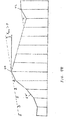
- the first situation is illustrated in Figure 8, which shows an inflated and filtered terrain profile h ( s ) . ⁇ 0 >0 and the third elevation h ( s 3 ) of inflated and filtered terrain profile h ( s ) is lower than h 0 +tan ⁇ 0 ds .
- the default rule substitutes line segments 101 and 103 for the first two line segments of terrain profile h(s), thereby creating a fictitious local elevation maximum at the second sample point s 2 of the frame, and the flight profile shaping algorithm seeks to create a flight profile that is horizontal at s 2 .
- the solution to this problem is to create, instead, an ad hoc flight profile that starts from altitude h 0 with the flight angle ⁇ 0 and flattens out to horizontal at the minimum allowed acceleration a Zmin .
- An analogous procedure is followed at the end of the last frame if ⁇ f ⁇ 0 and the third from last elevation of the inflated and filtered profile is lower than h f -tan ⁇ f ds .
- the second situation is related to the third subphase. Recall that the "third" piecewise linear approximation, that defines the flight profile, is at the maximum allowed acceleration a Zmax . If a frame, subsequent to the first frame, starts at a point in the previous frame at which the flight profile was defined in this way, then, because of numerical uncertainty, the flight profile computed for the previous frame is liable to intersect the envelope that is computed by the second subphase of the phase III algorithm, rather than be tangent to that envelope. The algorithm would then seek to back off (to the left) by another sample point; but because the algorithm is operating at the beginning of a frame, there is no sample point to back off to. Therefore, the initial flight slope is increased sufficiently to keep the flight profile from intersecting the envelope that is computed by the second subphase.
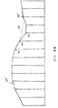
- Figure 9 shows two successive frames 110 and 112, the associated terrain profile 114, and the flight profile 116 computed as described above for frame 110 .
- Terrain profile 114 includes a cliff 120 in frame 112 but not in frame 110.
- This problem is handled by making the frames sufficiently long.
- the minimum frame length should be at least as great as the longest distance between two points, of the regional map from which the nominal terrain profile is obtained, such that the slope of the line of sight between the two points is greater than or equal to tan ⁇ max .
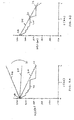
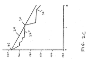
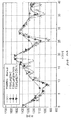
- Figures 10A, 10B and 10C show, respectively, three different portions of the terrain profile (marked with X's), along with three flight profiles.
- the flight profile marked with diamonds was computed without filtering the terrain profile.
- the flight profile marked with circles was computed after filtering the terrain profile with a 1 Km long filter.
- the flight profile marked with triangles was computed after filtering the terrain profile with a 3.5 Km long filter.
- Figure 10A shows the first 40 Km of the terrain profile and the three flight profiles.
- Figure 10B shows the next 40 Km of the terrain profile and the three flight profiles.
- Figure 10C shows the last 30 Km of the terrain profile and the three flight profiles.
- the flight profile that was computed using a relatively short 1-Km filter follows the terrain profile better than either the flight profile that was computed without filtering or the flight profile that was computed using a relatively long 3.5 Km filter.
- the 3.5 Km long filter produces a flight profile that requires gentler maneuvers than the other two flight profiles.
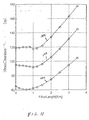
- Figure 11 shows three plots 130, 132 and 134 of the mean clearance of flight profiles above the inflated terrain profile as a function of the length of the filters that were used to filter the inflated terrain profile prior to computing the various flight profiles.
- Plot 130 refers to the entire 110 Km terrain profile.
- Plot 132 refers to the first 40 Km of the terrain profile, as shown in Figure 10A.
- Plot 134 refers to the last 30 Km of the terrain profile, as shown in Figure 10C.
- a 1 Km filter gives the closest terrain following for the terrain profile as a whole and also for the last 30 Km of the terrain profile.
- a 0.6 Km filter gives the closest terrain following for the first 40 Km of the terrain profile.
- the length of the filter that gives the closest terrain following depends on the nature of the terrain. It also should be remembered that terrain following is achieved at the expense of the increased fuel consumption needed to follow the terrain.
- the terrain profile filter length is selected in advance of the mission assigned to the air vehicle, in accordance with these two criteria. The nature of the mission determines the relative importance of the two criteria (closeness of terrain following vs. gentleness of maneuver) that are used to select the terrain profile filter length.
- FIG 12 is a schematic diagram of an air vehicle 150 of the present invention.
- On board air vehicle 150 are a memory 152 for storing a digital terrain map and (optionally, for an unmanned air vehicle 150 ) a flight path within the digital terrain map, two navigational instruments (a self-contained navigational instrument 155 such as an inertial measurement unit, and a second navigational instrument 156 , such as a GPS receiver, that relies on external signals) for determining the position and velocity of the air vehicle in real time, and a processor 154 for implementing the method of the present invention to compute a reference flight profile for air vehicle 150 in real time, in accordance with the digital terrain map stored in memory 152 , optionally in accordance with the flight path stored in memory 152 , in accordance with the position of air vehicle 150 as measured by navigational instruments 155 and 156 , and in accordance with the time-varying performance parameters of air vehicle 150 .
- Air vehicle 150 also includes a propulsion and guidance system, represented in Figure 12 by jet engines 158 and control surfaces
Landscapes
- Engineering & Computer Science (AREA)
- Aviation & Aerospace Engineering (AREA)
- Radar, Positioning & Navigation (AREA)
- Remote Sensing (AREA)
- Physics & Mathematics (AREA)
- General Physics & Mathematics (AREA)
- Automation & Control Theory (AREA)
- Navigation (AREA)
- Control Of Position, Course, Altitude, Or Attitude Of Moving Bodies (AREA)
- Radar Systems Or Details Thereof (AREA)
- Automatic Cycles, And Cycles In General (AREA)
Applications Claiming Priority (2)
| Application Number | Priority Date | Filing Date | Title |
|---|---|---|---|
| IL15989304 | 2004-01-15 | ||
| IL159893A IL159893A (en) | 2004-01-15 | 2004-01-15 | Method for performing a ground-following flight |
Publications (2)
| Publication Number | Publication Date |
|---|---|
| EP1560096A2 true EP1560096A2 (de) | 2005-08-03 |
| EP1560096A3 EP1560096A3 (de) | 2010-01-06 |
Family
ID=34073811
Family Applications (1)
| Application Number | Title | Priority Date | Filing Date |
|---|---|---|---|
| EP05250190A Withdrawn EP1560096A3 (de) | 2004-01-15 | 2005-01-14 | Geländefolgeverfahren |
Country Status (5)
| Country | Link |
|---|---|
| US (1) | US7321812B2 (de) |
| EP (1) | EP1560096A3 (de) |
| AU (1) | AU2005200149A1 (de) |
| IL (1) | IL159893A (de) |
| NO (1) | NO20050174L (de) |
Cited By (4)
| Publication number | Priority date | Publication date | Assignee | Title |
|---|---|---|---|---|
| FR2937156A1 (fr) * | 2008-10-09 | 2010-04-16 | Airbus France | Procede et dispositif de surveillance de la capacite de navigation d'un aeronef lors d'une phase de vol a proximite du sol. |
| US7765062B2 (en) | 2006-04-25 | 2010-07-27 | Honeywell International Inc. | Method and system for autonomous tracking of a mobile target by an unmanned aerial vehicle |
| FR2951296A1 (fr) * | 2009-10-09 | 2011-04-15 | Thales Sa | Procede de calcul d'alerte pour un systeme avertisseur de proximite du sol d'un aeronef |
| CN113064444A (zh) * | 2021-03-15 | 2021-07-02 | 中国南方电网有限责任公司超高压输电公司天生桥局 | 无人机下一飞行位置的预测方法、装置、设备和存储介质 |
Families Citing this family (13)
| Publication number | Priority date | Publication date | Assignee | Title |
|---|---|---|---|---|
| FR2875916B1 (fr) * | 2004-09-28 | 2015-06-26 | Eurocopter France | Procede et dispositif d'aide au pilotage d'un aeronef a voilure tournante au voisinage d'un point de pose ou de decollage |
| FR2881533B1 (fr) * | 2005-01-31 | 2007-04-20 | Airbus Sas | Procede et dispositif pour construire une trajectoire de vol a basse altitude destinee a etre suivie par un aeronef |
| FR2881534B1 (fr) * | 2005-02-01 | 2007-04-20 | Airbus Sas | Procede et dispositif pour determiner la largeur d'un corridor de securite pour un aeronef, ainsi que methode et systheme de securisation d'un vol automatique a basse altitude d'un aeronef |
| US20110029162A1 (en) * | 2006-03-06 | 2011-02-03 | Honeywell International, Inc. | Systems and methods for selectively altering a ground proximity message |
| FR2898972B1 (fr) * | 2006-03-21 | 2008-06-27 | Thales Sa | Procede et dispositif de surveillance de l'altitude de vol minimum d'un aeronef |
| FR2947370B1 (fr) | 2009-06-26 | 2011-11-25 | Eurocopter France | Procede d'aide au pilotage a basse altitude |
| US9324236B2 (en) * | 2011-11-23 | 2016-04-26 | The Boeing Company | System and methods for situation awareness, advisory, tracking, and aircraft control information |
| US9536435B1 (en) | 2015-07-13 | 2017-01-03 | Double Black Aviation Technology L.L.C. | System and method for optimizing an aircraft trajectory |
| US10121383B2 (en) * | 2016-01-26 | 2018-11-06 | Northrop Grumman Systems Corporation | Terrain profile system |
| FR3053780B1 (fr) * | 2016-07-07 | 2018-07-06 | Thales | Dispositif et methode de calcul de prediction de performance de navigation requise |
| DE102019003238B4 (de) * | 2019-05-08 | 2023-04-20 | Mercedes-Benz Group AG | Fahrzeugortung durch Kartenabgleich unter Berücksichtigung eines Straßenprofils |
| CN112256058B (zh) * | 2020-10-22 | 2023-11-21 | 广州极飞科技股份有限公司 | 一种定高触地确定方法、装置、设备及存储介质 |
| US12411499B2 (en) * | 2022-02-01 | 2025-09-09 | Lockheed Martin Corporation | Collision prevention flight control mode |
Citations (2)
| Publication number | Priority date | Publication date | Assignee | Title |
|---|---|---|---|---|
| EP0775953A1 (de) | 1995-11-21 | 1997-05-28 | Sextant Avionique | Steuermethode im Tiefflug |
| US5706011A (en) | 1995-06-07 | 1998-01-06 | Hughes Electronics | Method for determining terrain following and terrain avoidance trajectories |
Family Cites Families (7)
| Publication number | Priority date | Publication date | Assignee | Title |
|---|---|---|---|---|
| US3396391A (en) * | 1963-12-20 | 1968-08-06 | North American Rockwell | Terrain-following system |
| FR2658636B1 (fr) * | 1990-02-22 | 1994-08-26 | Sextant Avionique | Procede de pilotage d'un aeronef en vol a tres basse altitude. |
| US6005581A (en) * | 1994-01-18 | 1999-12-21 | Honeywell, Inc. | Terrain elevation path manager |
| EP1155285B1 (de) * | 1999-02-01 | 2004-07-07 | Honeywell International Inc. | Vorrichtung, verfahren und computerprogramm zur erzeugung einer bodenraumuntergrenze für eine ausgewählte landebahn |
| US6421603B1 (en) * | 1999-08-11 | 2002-07-16 | Honeywell International Inc. | Hazard detection for a travel plan |
| FR2857480B1 (fr) * | 2003-07-07 | 2005-09-30 | Airbus France | Procede et dispositif de generation d'un plan de vol pour un vol tactique d'un aeronef |
| EP1524500B1 (de) * | 2003-10-13 | 2014-08-06 | Saab Ab | Verfahren zur Planung einer Bewegungsbahn |
-
2004
- 2004-01-15 IL IL159893A patent/IL159893A/en active IP Right Grant
-
2005
- 2005-01-12 NO NO20050174A patent/NO20050174L/no unknown
- 2005-01-13 AU AU2005200149A patent/AU2005200149A1/en not_active Abandoned
- 2005-01-14 EP EP05250190A patent/EP1560096A3/de not_active Withdrawn
- 2005-01-18 US US11/035,728 patent/US7321812B2/en not_active Expired - Lifetime
Patent Citations (2)
| Publication number | Priority date | Publication date | Assignee | Title |
|---|---|---|---|---|
| US5706011A (en) | 1995-06-07 | 1998-01-06 | Hughes Electronics | Method for determining terrain following and terrain avoidance trajectories |
| EP0775953A1 (de) | 1995-11-21 | 1997-05-28 | Sextant Avionique | Steuermethode im Tiefflug |
Cited By (7)
| Publication number | Priority date | Publication date | Assignee | Title |
|---|---|---|---|---|
| US7765062B2 (en) | 2006-04-25 | 2010-07-27 | Honeywell International Inc. | Method and system for autonomous tracking of a mobile target by an unmanned aerial vehicle |
| FR2937156A1 (fr) * | 2008-10-09 | 2010-04-16 | Airbus France | Procede et dispositif de surveillance de la capacite de navigation d'un aeronef lors d'une phase de vol a proximite du sol. |
| US8275495B2 (en) | 2008-10-09 | 2012-09-25 | Airbus Operations Sas | Method and device for monitoring the ability to navigate of an aircraft during a phase of flight close to the ground |
| FR2951296A1 (fr) * | 2009-10-09 | 2011-04-15 | Thales Sa | Procede de calcul d'alerte pour un systeme avertisseur de proximite du sol d'un aeronef |
| US9047764B2 (en) | 2009-10-09 | 2015-06-02 | Thales | Method of alert calculation for an aircraft ground proximity warning system |
| CN113064444A (zh) * | 2021-03-15 | 2021-07-02 | 中国南方电网有限责任公司超高压输电公司天生桥局 | 无人机下一飞行位置的预测方法、装置、设备和存储介质 |
| CN113064444B (zh) * | 2021-03-15 | 2022-09-09 | 中国南方电网有限责任公司超高压输电公司天生桥局 | 无人机下一飞行位置的预测方法、装置、设备和存储介质 |
Also Published As
| Publication number | Publication date |
|---|---|
| IL159893A (en) | 2008-11-26 |
| EP1560096A3 (de) | 2010-01-06 |
| NO20050174L (no) | 2005-07-18 |
| NO20050174D0 (no) | 2005-01-12 |
| AU2005200149A1 (en) | 2005-08-04 |
| IL159893A0 (en) | 2004-09-27 |
| US7321812B2 (en) | 2008-01-22 |
| US20050270224A1 (en) | 2005-12-08 |
Similar Documents
| Publication | Publication Date | Title |
|---|---|---|
| US7321812B2 (en) | Method of terrain following | |
| CN110727287B (zh) | 用于确定爬升剖面的方法和系统以及预测爬升剖面的方法 | |
| CN109656264B (zh) | 用于为飞行器生成到着陆地点的3d路径的计算机实施的方法和系统 | |
| EP3171133B1 (de) | Planung von kinematischer bewegung mit regionalen planungsbeschränkungen | |
| CN111650958B (zh) | 一种固定翼无人机起飞段切入航路点的在线路径规划方法 | |
| CN101095090B (zh) | 用于自动绕圈飞行的控制系统 | |
| US10260883B2 (en) | Methods and systems for optimal guidance based on energy state approximation | |
| US8352169B2 (en) | Method for assisting in the management of a flight in order to keep to a time constraint | |
| US8401790B2 (en) | Computing-time-efficient route determination along several preset path points with given connecting routes in-between | |
| US12153444B2 (en) | Route planning among no-fly zones and terrain | |
| JP5292315B2 (ja) | 航空機出発時の可変推力カットバックを生成する飛行管理システム | |
| US20150153740A1 (en) | Safe emergency landing of a uav | |
| EP2955482A1 (de) | Flugzeugbewegungsplanungsverfahren | |
| CN108388263A (zh) | 圆形航线自动飞行系统 | |
| KR101687711B1 (ko) | 비행체의 고도 산출 장치 및 그 방법 | |
| KR101844727B1 (ko) | 회전익 무인비행체를 이용한 바람 정보 추정 시스템 | |
| CN114115353A (zh) | 一种编队避障方法及装置 | |
| US20220139234A1 (en) | Variable energy management methods and systems | |
| CN108319292A (zh) | 一种无人飞行器的控制方法、控制台、飞行器及控制系统 | |
| CN111895998B (zh) | 一种大型固定翼无人飞行器分段堆栈式航路规划方法 | |
| Takahashi et al. | Development and flight testing of a flight control law for autonomous operations research on the RASCAL JUH-60A | |
| JP2019085040A (ja) | 飛行装置 | |
| CN118672293B (zh) | 一种用于鸟类追踪的无人机轨迹规划方法及系统 | |
| Rhee et al. | Autopilot design for a target drone using rate gyros and GPS | |
| WO2020187880A1 (fr) | Détermination d'une trajectoire raccourcie d'un mobile évoluant dans un corridor |
Legal Events
| Date | Code | Title | Description |
|---|---|---|---|
| PUAI | Public reference made under article 153(3) epc to a published international application that has entered the european phase |
Free format text: ORIGINAL CODE: 0009012 |
|
| AK | Designated contracting states |
Kind code of ref document: A2 Designated state(s): AT BE BG CH CY CZ DE DK EE ES FI FR GB GR HU IE IS IT LI LT LU MC NL PL PT RO SE SI SK TR |
|
| AX | Request for extension of the european patent |
Extension state: AL BA HR LV MK YU |
|
| PUAL | Search report despatched |
Free format text: ORIGINAL CODE: 0009013 |
|
| AK | Designated contracting states |
Kind code of ref document: A3 Designated state(s): AT BE BG CH CY CZ DE DK EE ES FI FR GB GR HU IE IS IT LI LT LU MC NL PL PT RO SE SI SK TR |
|
| AX | Request for extension of the european patent |
Extension state: AL BA HR LV MK YU |
|
| 17P | Request for examination filed |
Effective date: 20100705 |
|
| AKX | Designation fees paid |
Designated state(s): AT BE BG CH CY CZ DE DK EE ES FI FR GB GR HU IE IS IT LI LT LU MC NL PL PT RO SE SI SK TR |
|
| 17Q | First examination report despatched |
Effective date: 20100920 |
|
| GRAP | Despatch of communication of intention to grant a patent |
Free format text: ORIGINAL CODE: EPIDOSNIGR1 |
|
| STAA | Information on the status of an ep patent application or granted ep patent |
Free format text: STATUS: THE APPLICATION IS DEEMED TO BE WITHDRAWN |
|
| 18D | Application deemed to be withdrawn |
Effective date: 20111021 |