EP1560083A2 - Timepiece having mainspring winding state display apparatus - Google Patents
Timepiece having mainspring winding state display apparatus Download PDFInfo
- Publication number
- EP1560083A2 EP1560083A2 EP05250377A EP05250377A EP1560083A2 EP 1560083 A2 EP1560083 A2 EP 1560083A2 EP 05250377 A EP05250377 A EP 05250377A EP 05250377 A EP05250377 A EP 05250377A EP 1560083 A2 EP1560083 A2 EP 1560083A2
- Authority
- EP
- European Patent Office
- Prior art keywords
- winding
- wheel
- mainspring
- timepiece
- gear
- Prior art date
- Legal status (The legal status is an assumption and is not a legal conclusion. Google has not performed a legal analysis and makes no representation as to the accuracy of the status listed.)
- Granted
Links
Images






Classifications
-
- G—PHYSICS
- G04—HOROLOGY
- G04B—MECHANICALLY-DRIVEN CLOCKS OR WATCHES; MECHANICAL PARTS OF CLOCKS OR WATCHES IN GENERAL; TIME PIECES USING THE POSITION OF THE SUN, MOON OR STARS
- G04B9/00—Supervision of the state of winding, e.g. indicating the amount of winding
- G04B9/005—Supervision of the state of winding, e.g. indicating the amount of winding by optical indication of the amount of winding
Definitions
- the present invention relates to a timepiece having a mainspring winding state display apparatus having a function of displaying a state of winding a mainspring constituting a power source of a mechanical time piece.
- the invention relates to a timepiece having a mainspring winding state display apparatus constituted to be able to arrange a mainspring winding state display member (power reserve indicator) at an arbitrary pertinent position in a movement of the time piece.
- a time piece having a mainspring winding state display apparatus of a first type of a background art includes a mechanism (power reserve mechanism) for displaying a remaining time period in which a mainspring can operate, that is, a duration of the timepiece.
- a power reserve mechanism uses a planetary gear mechanism for reciprocating a hand for displaying the duration of the timepiece in a fan-like shape.
- the timepiece having the mainspring winding state display apparatus of the first type of the background art is constituted by a ratchet wheel, a planetary gear mechanism constituted by a planetary intermediate gear brought in mesh with a barrel complete, a planetary wheel rotatably attached to an eccentric portion of the planetary intermediate gear, a sun gear brought in mesh with a planetary pinion, and a second sun wheel brought in mesh with a planetary gear, a display transmission wheel brought in mesh with a sun pinion, a display wheel brought in mesh with a display transmission pinion, a display degree determining pin, and a planetary transmission wheel brought in mesh with the ratchet wheel and a second sun gear (refer to, for example, JP-A-9-21886).
- a timepiece having a mainspring winding state display apparatus of a second type of a background art is provided with a planetary intermediate gear provided to be able to rotate by rotation of a barrel complete gear, a planetary wheel rotatably provided to the planetary intermediate gear by constituting a rotational center at a portion different from a rotational center of the planetary intermediate gear and having a first planetary wheel and a second planetary wheel rotatable integrally, a first sun wheel rotatably provided by constituting a rotational center by the rotational center of the planetary intermediate gear and having a first sun gear brought in mesh with a second planetary wheel, a second sun wheel provided rotatably by constituting a rotational center by the rotational center of the first sun wheel and having a second sun gear brought in mesh with a ratchet transmission wheel and a second sun pinion brought in mesh with the first planetary wheel, a claw wheel attached to the first sun wheel and having one or more feed claws, a winding mark intermediate wheel provided rotatably intermittent
- a rotational center of the mainspring winding state displaymember (that is, windingmarkhand: power reserve indicator) is arranged at a vicinity of a rotational center of the barrel complete gear. Therefore, in the timepiece having the mainspring winding state display apparatus, with regard to arrangement of a plurality of indicators (hour hand, minute hand, second hand, winding mark hand or the like), there is a restriction in view of design.
- the timepiece in a timepiece having a mainspring winding state display apparatus having a function of displaying a state of winding a mainspring constituting a power source of a mechanical timepiece, the timepiece includes a barrel complete including a mainspring and a barrel gear and constituted to be able to be rotated only in one direction by winding back the mainspring by the barrel gear, a speed reducing mechanism for reducing a speed of rotation of the barrel gear, a segment gear capable of being rotated based on an output of the speed reducing mechanism, a winding mark display wheel capable of being rotated based on an operation of the segment gear, and a mainspring winding state display member for displaying a state of winding the mainspring based on rotation of the winding mark display wheel.
- a rotational center of the mainspring winding state displaymember (that is, a rotational center of the winding mark hand) can be arranged at an arbitrary pertinent position in a movement of the timepiece regardless of a position of a rotational center of the barrel gear. Further, by the constitution, an influence of backlashes of mesh among gears for transmitting rotation to the winding mark hand can be reduced and operation of the winding mark hand can be prevented from being retarded.
- the timepiece having a mainspring winding state display apparatus of the invention such that the speed reducing mechanism is constituted by a planetary unit, the planetary unit includes a first sun wheel fixed to a barrel stem, a planetary wheel rotatably attached to a bottom face of the barrel gear and a second sun wheel rotatably attached to the barrel stem, and the planetary wheel is made to be able to be rotated while revolving around the first sun wheel when the barrel gear is rotated.
- the segment gear includes a first segment gear for receiving the output of the speed reducing mechanism and a second segment gear for rotating the winding mark display wheel.
- the timepiece having a mainspring winding state display apparatus of the invention includes a main plate, a hand setting stem, and an hour wheel.
- a main plate reference vertical axis line passing a rotational center of the hour wheel and substantially in parallel with a center axis line of the hand setting stem and a main plate reference horizontal axis line passing the rotational center of the hour wheel and orthogonal to the main plate reference vertical axis line are defined at the main plate and a first region disposed on one side of the main plate reference vertical axis line and disposed on a side of the main plate reference horizontal reference vertical axis line proximate to the hand setting stem, a second region disposed on other side of the main plate reference vertical axis line and disposed on a side of the horizontal axis line proximate to the hand setting stem, a third region disposed on the other side of the main plate reference vertical axis line where the second region is present and disposed on a side of the main plate reference horizontal axis line remote from the hand setting stem
- a rotational center of the barrel complete is arranged at the second region
- a rotational center of the speed reducing mechanism is arranged at the same position as the rotational center of the barrel complete and a rotational center of the winding mark display wheel is arranged at a region on the main plate reference vertical axis line and in a 3 o'clock direction of a dial.
- a timepiece having a mainspring winding state display apparatus of the invention is constituted to include a barrel complete, a speed reducing mechanism moved cooperatively with the barrel gear for reducing a speed of rotation of the barrel gear, a segment gear capable of being rotated based on an output of the speed reducing mechanism, a winding mark display wheel capable of being rotated based on operation of the segment gear, a mainspring winding state display member for displaying a state of winding the mainspring based on rotation of the winding mark display wheel, and a plurality of winding mark display wheel supporting portions for rotatably supporting the winding mark display wheel, wherein the winding mark display wheel is supported by one portion of the plurality of winding mark display wheel supporting portions, and the segment gear is constituted to transmit operation of the speed reducing mechanism to the winding mark display wheel supported by one portion of the plurality of winding mark display wheel supporting portions.
- a rotational center of a winding mark hand can be arranged at an arbitrary pertinent position in a movement of the timepiece. Further, since the plurality of winding mark display wheel supporting portions are provided in the movement, it is not necessary to prepare a plurality of movements for changing the position of the rotational center of the winding mark hand. Further, by the constitution, a small and thin timepiece having a mainspring winding state display apparatus can be realized.
- the timepiece having a mainspring winding state display apparatus of the invention such that the segment gear includes a first segment gear for receiving the output of the speed reducing mechanism and the first segment gear is made to rotate the winding mark display wheel. Further, it is preferable to constitute the timepiece having a mainspring winding state display apparatus of the invention such that the segment gear includes the first segment gear for receiving the output of the speed reducing mechanism and other segment gear, and the other segment gear is constituted to rotate the winding mark display wheel.
- a timepiece having a mainspring display apparatus includes a barrel complete, a speed reducing mechanismmoved cooperatively with the barrel gear for reducing a speed of rotation of the barrel gear, a winding mark display wheel rotated based on operation of the speed reducing mechanism, and a mainspring winding state display member for displaying a state of winding a mainspring based on rotation of the winding mark display wheel.
- the timepiece having the mainspring winding state display apparatus is characterized in that the speed reducing mechanism is constituted by a planetary unit, the planetary unit includes a first sun wheel fixed to a barrel stem, a planetary wheel rotatably attached to a bottom face of a barrel gear, and a second sun wheel rotatably attached to the barrel stem, the planetary wheel is constituted to be able to be rotated while revolving around the first sun wheel when the barrel gear is rotated, and is constituted to rotate the winding mark display wheel based on rotation of the second sun wheel.
- the speed reducing mechanism is constituted by a planetary unit
- the planetary unit includes a first sun wheel fixed to a barrel stem, a planetary wheel rotatably attached to a bottom face of a barrel gear, and a second sun wheel rotatably attached to the barrel stem
- the planetary wheel is constituted to be able to be rotated while revolving around the first sun wheel when the barrel gear is rotated, and is constituted to rotate the
- a rotational center of the winding mark hand can be arranged at an arbitrary pertinent position in a movement of the timepiece. Further, a plurality of winding mark display wheel supporting portions are provided in the movement and therefore, it is not necessary to prepare a plurality of movements for changing the position of the rotational center of the winding mark hand.
- a timepiece having a mainspring winding state display apparatus of the invention is provided with a movement 100.
- “Movement” indicates a machine body of the timepiece including a drive portion.
- “complete” indicates a finished body of a timepiece in which a dial, indicators (hour hand, minute hand, second hand and the like) , a crown and the like are attached to the movement of the timepiece to be contained in a time case (timepiece exterior).
- the movement 100 includes a main plate 102, a second main plate 112, and a date indicator maintaining plate 116.
- top side indicates a side of two faces of the main plate 102 remote from glass of the timepiece case, that is, “case back side”.
- back side indicates a side of the two faces of the main plate 102 proximate to the glass of the timepiece case, that is, “dial side”.
- the movement 100 further includes a first bridge 104, a second bridge 105, a pallet fork bridge 106, and a balance bridge 107.
- the second main plate 112, and the date indicator maintaining plate 116 are arranged on the back side of the main plate 102.
- a dial 110 is arranged on the side of the glass of the second main plate 112.
- the dial 110 is attached to the main plate 102 via a dial support ring 109.
- a hand setting stem 118 is integrated to the main plate 102 rotatably and movably in an axis line direction.
- a top side of the movement 100 is arranged with a top train wheel, an escaping mechanism, a speed control mechanism, an automatic winding mechanism, a hand winding mechanism, a switching apparatus, and a planetary mechanism for operating a mainspring winding state display mechanism.
- the hand winding mechanism may be deleted.
- the switching apparatus may be arranged on the back side of the movement 100.
- the hand winding mechanism may be arranged on the top side of the movement 100 and the automatic winding mechanism may be omitted.
- the back side of the movement 100 is arranged with a back train wheel, a date indicating mechanism, a date correcting mechanism, and a mainspring winding state display mechanism operated by a planetary mechanism.
- the top train wheel is roatatably supported by the main plate 102, the first bridge 104, and the second bridge 105.
- the back train wheel is rotatably supported by the main plate 102, the second main plate 112, and the date indicator maintaining plate 116.
- the date indicating mechanism and the date correcting mechanism may be omitted.
- a day indicating mechanism and a day correcting mechanism may be provided on the back side of the movement 100.
- a main plate reference vertical axis line 205 passing a rotational center 200 of an hour wheel 232 and substantially in parallel with a center axis line of the hand setting stem 118, and a main plate reference horizontal axis line 206 passing the rotational center 200 of the hour wheel 232 and orthogonal to the main plate reference vertical axis line 205 are defined at the main plate 102.
- the main plate 102 is provided with a first region 201 disposed on one side of the main plate reference vertical axis line 205 and disposed on a side of the main plate reference horizontal axis line 206 proximate to the hand setting stem 118, a second region 202 disposed on other side of the main plate reference vertical axis line 205 and disposed on a side of the main plate reference horizontal axis line 206 proximate to the hand setting stem 118, a third region 203 disposed on other side of the main plate reference vertical axis line 205 where the second region 202 is present and disposed on a side of the main plate reference horizontal axis line 206 remote from the hand setting stem 118, and a fourth region 204 disposed on the one side of the main plate reference vertical axis line 205 where the first region 201 is present and disposed on a side of the main plate reference horizontal axis line 206 remote from the hand setting stem 118.
- first region 201 and the fourth region 204 are present on a right side of the main plate reference vertical axis line 205
- the first region 201 and the fourth region 204 may be defined to be disposed on a left side of the main plate reference vertical axis line 205.
- the second region 202 and the third region 203 are defined to dispose on a right side of the main plate reference vertical axis line 205.
- an arrangement of a part in the movement may be arranged as illustrated, or may be arranged to constitute line symmetry (mirror image) relative to the arrangement illustrated by constituting an axis of symmetry by the main plate reference vertical axis line 205.
- the barrel complete 120 is rotatably supported by the barrel bridge 104 and the main plate 102.
- the barrel complete 120 includes a mainspring 120b, a barrel stem 120c, a barrel gear 120d, and a barrel lid 120f.
- the mainspring 120b constitutes a power source of the mechanical timepiece.
- the barrel gear 120d is rotated in one direction and indicates time information by indicators (hour hand, minute hand, second and the like) via rotation of the top train wheel and a back train wheel.
- Rotation of the barrel gear 120d rotated by power of the mainspring 120b is controlled by a speed control apparatus and an escaping apparatus.
- the speed control apparatus includes a barrel with hairspring 142.
- the escaping apparatus includes a pallet fork 144 and an escape wheel & pinion 146.
- the balance with hairspring 142 is rotatably supported by the barrel bridge 107 and the main plate 102.
- the pallet fork 144 is rotatably supported by the pallet fork bridge 106 and the main plate 102.
- the escape wheel & pinion 146 is rotatably supported by the first bridge 104 and the main plate 102.
- a center wheel & pinion 122 is constituted to be rotated by one rotation per hour by rotation of the barrel gear 120d.
- the center wheel & pinion 122 is rotatably supported by the second bridge 105 and the main plate 102.
- a third wheel & pinion 124 is constituted to be rotated by rotation of the center wheel & pinion 122.
- the third wheel and pinion 124 is rotatably supported by the first bridge 104 and the main plate 102.
- a second wheel & pinion 126 is constituted to be rotated by one rotation per minute by rotation of the third wheel & pinion 124.
- the second wheel & pinion 126 is rotatably supported by the first bridge 104 and the main plate 102.
- a rotational speed of the second wheel & pinion 126 is constituted to be controlled by the escape wheel & pinion 146.
- a rotational speed of the escape wheel & pinion 146 is constituted to be controlled by the pallet fork 144. Pivoting movement of the pallet fork 144 is constituted to be controlled by the balance with hairspring 142.
- the top train wheel includes the center wheel & pinion 122, the third wheel & pinion 124 and the second wheel & pinion 126.
- a minute hand 246 attached to the center wheel & pinion 122 is constituted to indicate "minute”.
- a second hand 248 attached to the second wheel & pinion 126 is constituted to indicate "second”.
- a rotational center of the second wheel & pinion 126 and a rotational center of the center wheel & pinion 122 are constituted to be disposed at the same position.
- a square hole portion of the ratchet wheel 130 is integrated to a square shaft portion 120h provided at an upper portion (a side of the first bridge 104) of the barrel stem 120c of the barrel complete 120.
- the ratchet wheel 130 is supported to be rotated integrally with the barrel stem 20c by a square hole stop screw 132.
- the ratchet wheel 130 can be rotated only in the same direction as a direction of rotating the barrel complete 120.
- a detent 131 constituting a rotation rectifying member is provided at the first bridge 104 for rectifying rotation of the ratchet wheel 130 only in one direction.
- the ratchet wheel 130 can be hampered from being rotated in a direction opposed to the direction of rotating the barrel complete 120 by the detent 131.
- the hand winding mechanism includes a clutch wheel 272, a winding pinion 133, a crown wheel 134 and a crown transmission wheel 135.
- the winding pinion 133 is constituted to be rotated by rotation of the clutch wheel 272 in one direction.
- the crown transmission wheel 135 is constituted to be rotated by rotation of the winding pinion 133 via rotation of the crown wheel 134.
- the ratchet wheel 130 is constituted to be rotated in the clockwise direction by the rotation of the crown transmission wheel 135.
- the balance with hairspring 120b is constituted to be able to be wound by the rotation of the ratchet wheel 130.
- an automatic winding mechanism for winding up the balance with hairspring 120b is provided on the top side of the movement 100.
- the automatic winding mechanism includes an oscillating weight 210, a first transmission wheel 212, a pawl lever 214 and a second transmission wheel 216.
- the oscillating weight 210 is rotatably integrated to the first bridge 104 via a ball bearing 210b.
- the first transmission wheel 212 is rotatably supported by the first bridge 104 and the main plate 102.
- a gear portion of the first transmission wheel 212 is constituted to be brought in mesh with an oscillating weight pinion 210c of the oscillating weight 210.
- a hole (not illustrated) of a base portion of the pawl lever 214 is rotatably integrated to an eccentric cam portion (not illustrated) of the first transmission wheel 212.
- the pawl lever 214 includes two pawl portions, that is, a pull pawl 214f and a push pawl 214g.
- the second transmission wheel 216 is rotatably supported by the first bridge 104.
- the pull pawl 214f and the push pawl 214g of the pawl lever 214 are constituted to be brought in mesh with ratchet teeth (not illustrated) of the second transmission wheel 216.
- the pawl lever 214 is constituted to be operated by rotating the first transmission wheel 212.
- the pull pawl 214f of the pawl lever 214 is constituted to be able to rotate the second transmission wheel 216 only in one direction (counterclockwise direction in Fig. 2).
- the push pawl 214g of the pawl lever 214 is constituted to be able to rotate the second transmission wheel 216 only in one direction (counterclockwise direction in Fig.2). Therefore, when the oscillating weight 210 is rotated, the pawl lever 214 is operated, and the ratchet wheel 130 is constituted to be rotated in the clockwise direction based on rotation of the second transmission wheel 216. As a result, when the oscillating weight 210 is rotated, the balance with hairspring 210b can be wound up by operating the automatic winding mechanism.
- a back train wheel includes a minute wheel 230 and an hour wheel 232.
- the minute wheel 230 is constituted to be rotated by rotation of the center wheel and pinion 122.
- the hour wheel 232 is constituted to be rotated by one rotation per 12 hours by rotation of the minute wheel 230.
- An hour hand 244 attached to the hour wheel 232 indicates "hour”.
- a rotational center of the hour wheel 232 and a rotational center of the center wheel & pinion 122 are constituted to be disposed at the same position. It is preferable to arrange the rotational center of the minute wheel 230 on the main plate reference vertical axis line 205.
- the switching mechanism and a time setting mechanism are provided in order to set time of the timepiece.
- the switching mechanism is constituted to include a setting lever 236, a yoke 237 and a yoke holder 238.
- the time setting mechanism includes a hand setting stem 118 and a clutch wheel 272.
- the square hole portion of the clutch wheel 272 is integrated to the square shaft portion of the hand setting stem 118.
- a position of the hand setting stem 118 in a direction along a center axis line of the hand setting stem 118 is determined by a switching apparatus (setting lever, yoke and the like).
- a position of the clutch wheel 272 in the direction along the center axis line of the hand setting stem 118 is determined by the switching apparatus (setting lever, yoke, yoke holder and the like).
- the clutch wheel 272 includes an A tooth 272a disposed on a side proximate to a center portion of the movement 100 and a B tooth 272b disposed on a side proximate to an outer shape portion of the movement 100.
- the B tooth 272b of the clutch wheel 272 is constituted by a ratchet gear.
- the winding pinion 133 includes a winding small gear 133b constituted to be able to be brought in mesh with the B tooth 272b of the clutch wheel 272 and a winding large gear 133c constituted to be able to be brought in mesh with a gear portion of the crown wheel 134.
- the winding small gear 133b is constituted by a ratchet gear.
- the A tooth 272a of the clutch wheel 272 is constituted not to be brought in mesh with the gear portion of the minute wheel 230.
- the B tooth 272b of the clutch wheel 272 is constituted to be brought in mesh with the small gear 133b of the winding pinion 133.
- the A tooth 272a of the clutch wheel 272 is constituted to be brought in mesh with the gear portion of the hour wheel 230.
- the A tooth 272a of the clutch wheel 272 is constituted not to be brought in mesh with the small gear 133b of the winding pinion 133.
- the mainspring 120b is constituted to be able to be wound up by rotating the clutch wheel 272 along with the hand setting stem 118 and rotating the ratchet wheel 130 via rotation of the winding pinion 133, the crown wheel 134 and the crown transmission wheel 135.
- a date indicator feeding mechanism is constituted to be operated based on rotation of the back train wheel.
- the date indicator feeding mechanism includes a date indicator driving wheel 250, an intermediate date indicator driving wheel 251 and a date indicator 252.
- the intermediate date indicator driving wheel 251 is constituted to be rotated by rotation of the hour wheel 232.
- the date indicator driving wheel 250 is constituted to be rotated by rotation of the intermediate date indicator driving wheel 251.
- the date indicator 252 is constituted to be rotated by (1/31) once per day by a date feeding pawl 250b provided at the date indicator driving wheel 250.
- the date indicator 252 is constituted to be rotated by one rotation per 31 days. A position in a rotational direction of the date indicator 252 is rectified by a date jumper 253. Date characters 252c from "1" to "31” provided at the date indicator 252 are constituted to indicate "date" (refer to Fig.5).
- the timepiece of the invention can be provided with a date correcting mechanism for correcting display of date by the date indicator 252.
- the date correcting mechanism is constituted by the clutch wheel 272, the winding pinion 133, a first corrector transmission setting wheel 257, a first corrector transmission setting wheel 258 and a corrector setting wheel 259.
- the clutch wheel 272 When the hand setting stem 118 is rotated in one direction in a state of setting the hand setting stem 118 to 1 stage, the clutch wheel 272 is rotated, the corrector setting wheel 259 is pivoted in one direction to stop at a first position via rotation of the winding pinion 133 and the first corrector transmission setting wheel 257, and is constituted to be able to rotate the date indicator 252 by rotating the corrector setting wheel 259 at the first position.
- the date indicator 252 is constituted not to be able to be rotated even when the hand setting stem 118 is rotated in other direction in the state of setting the hand setting stem 118 to 1 stage.
- the mainspring winding state display mechanism includes a planetary mechanism.
- the planetary mechanism constitutes a speed reducing mechanism cooperatively moved with a barrel gear 120d for reducing the speed of rotation of the barrel gear 120d.
- the planetary mechanism includes a first sun wheel 150, a first planetary wheel 152, a second planetary wheel 154 and a second sun wheel 156.
- the first sun wheel 150 is fixed to a lower shaft portion 120h provided at a lower middle portion of a barrel stem 120c of the barrel complete 120, portion on a side of the main plate 102 and on a side most proximate to a bottom face of the barrel gear 120d.
- the first planetary wheel 152 is attached rotatably to the bottom face of the barrel gear 120d.
- the second planetary wheel 154 is rotatably attached to the bottom face of the barrel gear 120d.
- the second sun wheel 156 is rotatably attached to a lower front end shaft portion of the barrel stem 120c of the barrel complete 120 (portion mostly proximate to the main plate 102).
- the first sun wheel 150 is constituted to be brought in mesh with the first planetary wheel 152.
- the first planetary wheel 152 is constituted to be brought in mesh with the second planetary wheel 154.
- the second planetary wheel 154 is constituted to be brought in mesh with the second sun wheel 156.
- the first planetary wheel 152 is constituted to be able to be rotated while revolving around the first sun wheel 150.
- the second planetary wheel 154 is constituted to be able to be rotated while revolving around the first sun wheel 150. It is preferable to arrange a rotational center of the first sun wheel 150 at the second region 202.
- a first winding mark intermediate wheel 180 is rotatably supported by the main plate 102 and the date indicator maintaining plate 116.
- the first winding mark intermediate wheel 180 includes a first winding mark intermediate gear 180a and a first winding mark intermediate pinion 180b. It is preferable to arrange a rotational center of the first winding mark intermediate wheel 180 at the third region 203.
- a second winding mark intermediate wheel 182 is rotatably supported by the second main plate 112 and the date indicator maintaining plate 116.
- the second winding mark intermediate wheel 182 includes a second winding mark intermediate gear 182a and a second winding mark intermediate pinion 182b. It is preferable that a rotational center of the second winding mark intermediate wheel 182 is arranged at the third region 203.
- a winding mark drive wheel 184 is rotatably supported by the second main plate 112.
- the winding mark drive wheel 184 is arranged between the second main plate 112 and the date indicator maintaining plate 116.
- the winding mark drive wheel 184 includes a first segment portion 184b and a second segment portion 184f.
- a first segment gear 184c is provided at the first segment portion 184b.
- a second segment 184g is provided at the second segment portion 184f. It is preferable to constitute an outer diameter (pitch diameter) of the first segment gear 184c to be a dimension larger than an outer diameter (pitch diameter) of the second segment gear 184g. It is preferable that an opening angle of the first segment gear 184c is about 25 degrees.
- an opening angle of the second segment gear 184g is about 50 degrees.
- the winding mark drive wheel 184 constitutes a "deformed segment gear" having the two segment gears having the different outer diameters (pitch diameters).
- the first segment gear 184c is constituted to be brought in mesh with the second winding mark intermediate gear 182a.
- a winding mark indicator 190 is rotatably supported by the second main plate 112 and the date indicator maintaining plate 116.
- the winding mark indicator 190 includes a winding mark gear 190a.
- the winding mark gear 190a is constituted to be brought in mesh with the second segment gear 184g.
- a rotational center of the winding mark indicator 190 is arranged at a region on the main plate reference vertical axis line 205 and on a side proximate to the hand setting stem 118 (3 o'clock direction of the dial 110). It is preferable that a rotational center of the winding mark driving wheel 184 is arranged in a region on the main plate reference vertical axis line 205 and proximate to the hand setting stem 118.
- a rotational center of the winding mark drive wheel 184 is arranged at a region between the rotational center of the winding mark indicator 190 and a rotational center of the hour wheel 232.
- a winding mark hand 196 constituting a mainspring winding state display member is attached to a winding mark indicator stem of the winding mark indicator 190.
- the winding stem hand 196 constituting the main spring winding state display member is attached to the winding mark indicator stem of the winding mark indicator 190.
- a display sign 110a indicating a mainspring winding state is provided at the dial 110.
- the display sign 110a includes numerals of "0", "20", “40", "60".
- the user can know a state of winding the mainspring by a position of a front end of the winding mark hand 196 and the display sign 110a.
- the rotational center of the winding mark hand 196 (that is, rotational center of power reserve indicator) can be arranged at an arbitrary pertinent position in the movement 100 of the timepiece regardless of a position of the rotational center of the barrel gear 120d.
- an influence of backlashes of mesh among the gears for transmitting rotation to the winding mark hand 196 can be reduced and operation of the winding mark hand 196 can effectively be prevented from being retarded.
- the first winding mark intermediate wheel 180 is rotated by rotation of the second sun wheel 156.
- the second winding mark intermediate wheel 182 is rotated by rotation of the first winding mark intermediate wheel 180.
- the winding mark drive wheel 184 is rotated by rotation of the second winding mark intermediate wheel 182.
- the winding mark indicator 190 is rotated in the clockwise direction by rotation of the winding mark drive wheel 184.
- the winding mark hand 196 is rotated in the clockwise direction, the winding mark hand 196 is brought into a state of indicating "60" of the display sign 110a from a state of indicating "0" of the display sign 110a by the winding mark hand 196, via a state of indicating "20" of the display sign 110a by the winding mark hand 196, further, via a state of indicating "40" by the winding mark hand 196.
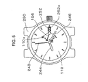
- a state shown in Fig. 5 indicates a state in which the winding mark hand 196 slightly passes a state of "2/3 winding" of the mainspring.
- the mainspring cannot be wound up more than a state of "full winding” by the mainspring.
- a portion of a slipping attachment (not illustrated) provided in the barrel complete 120 is slipped.
- the winding hand 196 can be hampered from being rotated further in the counterclockwise direction.
- the first winding mark intermediate wheel 180 is rotated by rotation of the second sun wheel 156.
- the second winding mark intermediate wheel 182 is rotated by rotation of the first winding mark intermediate wheel 180.
- the winding mark drive wheel 184 is rotated by rotation of the second winding mark intermediate wheel 182.
- the winding mark display wheel 190 is rotated in the counterclockwise direction by rotation of the winding mark drive wheel 184. Therefore, as winding back (releasing) the mainspring 120b by rotating the barrel complete 120, the winding mark hand 196 is rotated in the counterclockwise direction at a speed lower than a normal rotational speed of the train wheel.
- the winding mark hand 196 is brought into the state of indicating "0" of the display sign 110a from the state of indicating "60" of the display sign 110a by the winding mark hand 196, via the state of indicating "40” of the display sign 110a by the winding mark hand 196 and via a state of bringing the winding mark hand 196 into the state of indicating "20" of the display sign 110a.
- the display sign 110a may be constituted to indicate a "full winding" state of the mainspring by "1”, indicate a "half winding” state of the mainspring by "1/2" and indicate a "release” state of the mainspring by "0".
- the display sign 110a may be constituted to indicate the "full winding" state of the mainspring by "100 %”, indicate the "half winding” state of the mainspring by “50 %” and indicate the "release” state of the mainspring by "0 %”.
- the display sign 110a may be constituted to indicate the "full winding” state of the mainspring by “black circle sign”, indicate the "half winding” state of the mainspring by “semicircle sign” and indicate the "release” state of the mainspring by "white circle sign”.
- a complete of the timepiece having the mainspring winding state display apparatus of the invention includes a timepiece case 290.
- Themovement 100 of the timepiece having the mainspring winding state display apparatus is contained in the timepiece case 290.
- "Hour” of the current time is indicated by the hour hand 244.
- "Minute” of the current time is indicated by the minute hand 246.
- "Second” of the current time is indicated by the second hand 248.
- Current “date” is indicated by the date character 252c provided at the date indicator 252.
- the display sign 110a provided at the dial 110 indicates the duration capable of operating the timepiece having the mainspring winding state display apparatus.
- the winding mark hand 196 indicates a position of slightly passing "40" of the display sign 110a.
- the state shows that the duration of the mainspring is equal to or longer than 40 hours.
- An angle of rotating the winding mark hand 196 from the "full winding" state of the mainspring is constituted to correspond to the duration of the timepiece.
- the rotational center of the winding mark display wheel 190 is arranged in a region on the main plate reference horizontal axis line 206 in 6 o'clock direction of the dial 110.
- a winding mark drive wheel 324 is rotatably supported by the second main plate 112. It is preferable that a rotational center of the winding mark drive wheel 324 is arranged at a region on the main plate reference vertical axis line 205 in 3 o'clock direction of the dial 110.
- the rotational center of the winding mark drive wheel 324 is arranged at a region between a rotational center of the winding mark display wheel 190 and a rotational center of the hour wheel 232.
- the winding mark drive wheel 324 includes a first segment portion 324b and a second segment portion 324f.
- a first segment gear 324c is provided at the first segment portion 324b. It is preferable to constitute an outer diameter (pitch diameter) of the first segment gear 324c to be a dimension substantially the same as an outer diameter (pitch diameter) of a second segment gear 324g.
- the outer diameter (pitch diameter) of the first segment gear 324c may be constituted to differ from the outer diameter (pitch diameter) of the second segment gear 324g. It is preferable that an opening angle of the first segment gear 324c is about 25 degrees.
- the second segment gear 324g is provided at the second segment portion 324f. It is preferable that an opening angle of the second segment gear 324g is about 60 degrees.
- the winding mark drive wheel 324 constitutes "deformed segment gear” including the two segment gears.
- the first segment gear 324c is constituted to be brought in mesh with the second winding mark intermediate gear 182a.
- the winding mark indicator 190 is rotatably supported by the second main plate 112 and the date indicator maintaining plate 116.
- the winding mark indicator 190 includes a winding mark gear 190a.
- the second segment gear 324g is constituted to be brought in mesh with the winding mark gear 190a.
- the second main plate 112, the date indicator holder 116, and the winding mark indicator 190 are constituted to be able to integrate the winding mark display wheel 190 at a plurality of positions to be able to be applied to both the first embodiment and the second embodiment of the timepiece having the mainspring winding state display apparatus of the invention. It is preferable to constitute the second main plate 112 to be able to integrate the winding mark indicator 190 at other position so as to be able to be applied also to a constitution for providing the winding mark indicator 190 at other position.
- the mainspring winding state can be displayed by the winding mark hand 196 by constituting the rotational center by a plurality of positions by using the single movement and therefore, timepieces having a plurality of designs can easily be realized.
- the movement 320 of the timepiece having the mainspring winding state display apparatus is contained in the timepiece case 290.
- a display sign 328a provided at a dial 328 indicates a duration capable of operating the timepiece having the mainspring winding state display apparatus.
- the winding mark hand 196 indicates a position of slightly passing "40" of the display sign 328a.
- the rotational center of the winding mark indicator 190 is arranged at a region on the main plate reference vertical axis line 205 and in 9 o' clock direction of the dial 110.
- a winding mark drive wheel 334 is rotatably supported by the second main plate 112. It is preferable that a rotational center of the winding mark drive wheel 334 is arranged at a region on the main plate reference vertical axis line 205 and in 3 o'clock direction of the dial 110.
- the rotational center of the winding mark drive wheel 324 is arranged at a region between the rotational center of the winding mark indicator 190 and the rotational center of the hour wheel 232.
- the winding mark drive wheel 324 includes a first segment portion 324b and a second segment portion 324f.
- a first segment gear 324c is provided at the first segment portion 324b.
- a second segment gear 324g is provided at the second segment portion 324f. It is preferable to constitute the outer diameter (pitch diameter) of the first segment gear 324c to be a dimension substantially the same as the outer diameter (pitch diameter) of the second segment gear 324g.
- the outer diameter (pitch diameter) of the first segment gear 324c may be constituted to differ from the outer diameter (pitch diameter) of the second segment gear 324g. It is preferable that the opening angle of the first segment gear 324c is about 25 degrees. It is preferable that the opening angle of the second segment gear 324g is about 60 degrees.
- a winding mark drive transmission wheel 336 is rotatably supported by the second main plate 112.
- a gear portion of the winding mark drive transmission wheel 336 is constituted to be brought in mesh with the second segment gear 324g.
- the winding mark gear 190a is constituted to be brought in mesh with the gear portion of the winding mark drive transmission wheel 336.
- the winding mark indicator 190 is rotatably supported by the second main plate 112 and the date indicator maintaining plate 116.
- the winding mark indicator 190 includes the winding mark gear 190a.
- the winding mark gear 190a is constituted to be brought in mesh with the second segment gear 324g.
- the secondmain plate 112, the date indicator maintaining plate 116, the winding mark drive wheel 324 and the winding mark indicator 190 are constituted to be able to integrate the same winding mark indicator 190 in plural positions in order to be able to be applied to both the second embodiment and the third embodiment of the timepiece having the main plate winding state display apparatus of the invention. It is preferable that the secondmain plate 112 and the date indicator maintaining plate 116 are constituted to be able to integrate the winding mark indicator 190 at other position to be able to be applied also to a constitution for providing the winding mark indicator 190 at other position.
- the first winding mark intermediate wheel 180 is rotated via operation of the planetary mechanism.
- the second winding mark intermediate wheel 182 is rotated by rotation of the first winding mark intermediate wheel 180.
- the winding mark drive wheel 334 is rotated by rotation of the second winding mark intermediate wheel 182.
- the winding mark drive transmission wheel 336 is rotated by rotation of the winding mark drive wheel 184.
- the winding mark indicator 190 is rotated in the counterclockwise direction by rotation of the winding mark drive transmission wheel 336.
- the first winding mark intermediate wheel 180 is rotated by rotation of the barrel gear 120d via operation of the planetary mechanism.
- the second winding mark intermediate wheel 182 is rotated by rotation of the first winding mark intermediate wheel 180.
- the winding mark drive wheel 184 is rotated by rotation of the second winding mark intermediate wheel 182.
- the winding mark drive transmission wheel 336 is rotated by rotation of the winding mark drive wheel 184.
- the winding mark indicator 190 is rotated in the clockwise direction by rotation of the winding mark drive transmission wheel 336. Therefore, as winding back (releasing) the mainspring 120b by rotating the barrel complete 120, the winding mark hand 196 is rotated in the clockwise direction at a speed slower than a normal rotational speed of the train wheel.
- the winding mark drive wheel 334 constitutes "deformed segment gear” having two segment gears having the outer diameters (pitch diameters) of substantially the same dimension.
- the rotational center of the winding mark hand 196 (that is, rotational center of the power reserve indicator) can be arranged at an arbitrary pertinent position in the movement of the timepiece regardless of the position of the rotational center of the barrel gear 120d. Further, by the constitution, an influence of backlashes of mesh among gears for transmitting rotation to the winding mark hand 196 can be reduced and operation of the winding mark hand 196 can effectively be prevented from being retarded.
- the mainspring winding state can be displayed by constituting the rotational center by a plurality of positions and therefore, timepieces having a plurality of designs can easily be realized.
- the movement 330 of the timepiece having the mainspring winding state display apparatus is contained in the timepiece case 290.
- a display sign 338a provided at a dial 338 indicates a duration capable of operating the timepiece having the mainspring winding state display apparatus.
- the winding hand 196 indicates a position slightly passing "40" of the display sign 338a.
- the rotational center of the winding display wheel 190 is arranged in a region on the main plate reference vertical axis line 205 and in 3 o'clock direction of the dial 110.
- a winding mark drive wheel 344 is rotatably supported by the second main plate 112. It is preferable that a rotational center of the winding mark drive wheel 344 is arranged at the same position as the rotational center 200 of the hour wheel 232.
- the winding mark drive wheel 344 includes a first segment portion 344a, a second segment portion 344c and a third segment portion 344f.
- the first segment portion 344a is arranged at a region between substantially 12 o' clock direction and substantially 4 o'clock direction of the dial 110.
- the second segment portion 344c is arranged at a region between substantially 6 o'clock direction and substantially 7 o'clock direction of the dial 110.
- the third segment portion 344f is arranged at a region between substantially 9 o'clock direction and substantially 10 o'clock direction of the dial 110.
- a first segment gear 344b is provided at the first segment portion 344a.
- a second segment gear 344d are provided at the second segment portion 344c.
- a third segment gear 344g is provided at the segment portion 344f. It is preferable to constitute such that an outer diameter (pitch diameter) of the first segment gear 344b, an outer diameter (pitch diameter) of the second segment gear 344d and an outer diameter (pitch diameter) of the third segment gear 344g are constituted by the same dimension. It is preferable that an opening angle of the first segment gear 344a is about 130 degrees. It is preferable that an opening angle of the second segment gear 344d is about 40 degrees. It is preferable that an opening angle of the third segment gear 344g is about 40 degrees.
- a portion of the first segment gear 344b is constituted to be brought in mesh with the second winding mark intermediate gear 182a. Other portion of the first segment gear 344b is constituted to be brought in mesh with the winding mark gear 190a.
- the winding mark drive wheel 344 constitutes "deformed segment gear” having the three segment gears having the outer diameters (pitch diameters) of the same dimension.
- the winding mark drive wheel 344 is constituted by the "deformed segment gear” because it is necessary to avoid the first corrector setting transmission wheel 257, the first corrector setting transmission wheel 258, the date indicator driving wheel 250 and the date jumper 253.
- the first segment gear 344b is constituted to be brought in mesh with the second winding mark intermediate gear 182a.
- the first segment gear 340b is constituted to be brought in mesh with winding mark gear 190a.
- the rotational center of the winding mark hand 196 (that is, rotational center of the power reserve indicator) can be arranged at an arbitrary pertinent position in the movement of the timepiece regardless of the position of the rotational center of the barrel gear 120d. Further, by the constitution, an influence of backlashes of mesh among gears for transmitting rotation to the winding mark hand 196 can be reduced and operation of the winding mark hand 196 can effectively be prevented from being retarded.
- the second main plate 112 is constituted to be able to integrate the winding mark drive wheel 344 at least at positions of 3 portions to be able to be applied to any of the fourth embodiment, the fifth embodiment and the sixth embodiment of the timepiece having the main plate winding state display apparatus of the invention.
- the second main plate 112, the date indicator maintaining plate 116, the winding mark drive wheel 344, and the winding mark indicator 190 are constituted to be able to integrate the same winding mark indicator 190 at a plurality of positions to be able to be applied to any of the fourth embodiment, the fifth embodiment and the sixth embodiment of the timepiece having the mainspring winding state display apparatus of the invention. It is preferable to constitute the second main plate 112 and the date indicator maintaining plate 116 to be able to integrate the winding mark indicator 190 at other position to be able to be applied to also a constitution for providing the winding mark indicator 190 at other position. According to the invention, by using the single movement, the main plate winding state can be displayed by constituting the rotational center by a plurality of positions and therefore, timepieces having a plurality of designs can easily be realized.
- the rotational center of the winding mark indicator 190 is arranged at a region on the main plate reference horizontal axis line 206 and in 6 o'clock direction of the dial 110.
- the winding mark drive wheel 344 is rotatably supported by the second main plate 112. It is preferable that the rotational center of the winding mark drive wheel 344 is arranged at the same position as that of the rotational center 200 of the hour wheel 232.
- the first segment gear 344b is constituted to be brought in mesh with the second winding mark intermediate gear 182a.
- the second segment gear 344d is constituted to be brought in mesh with the winding mark gear 190a.
- the rotational center of the winding hand 196 (that is, rotational center of the power reserve indicator) can be arranged at an arbitrary pertinent position in the movement of the timepiece regardless of the position of the rotational center of the barrel gear 120d. Further, by the constitution, an influence of backlashes of mesh among gears for transmitting rotation to the winding mark hand 196 can be reduced and operation of the winding mark hand 196 can effectively be prevented from being retarded.
- the rotational center of the winding mark indicator 190 is arranged at a region on the main plate reference vertical axis line 205 and in 9 o'clock direction of the dial 110.
- the winding mark drive wheel 344 is roatably supported by the second main plate 112. It is preferable to arrange the rotational center of the winding mark drive wheel 344 at the same position as the rotational center 200 of the hour wheel 232.
- the first segment gear 344b is constituted to be brought in mesh with the second winding mark intermediate gear 182a.
- the third segment gear 344g is constituted to be brought in mesh with the winding mark gear 190a.
- the rotational center of the winding mark hand 196 (that is, rotational center of the power reserve indicator) can be arranged at an arbitrary pertinent position in the movement of the timepiece regardless of the position of the rotational center of the barrel gear 120d. Further, by the constitution, an influence of backlashes of mesh among gears for transmitting rotation to the winding mark hand 196 can be reduced and operation of the winding mark hand 196 can effectively be prevented from being retarded.
- a seventh embodiment of a timepiece having a mainspring winding state display apparatus of the invention will be explained.
- a description will mainly be given of points of the seventh embodiment of the timepiece having the mainspring winding state display apparatus of the invention different from the first embodiment of the timepiece having the mainspring winding state display apparatus of the invention. Therefore, the above-described explanation of the first embodiment of the timepiece having the mainspring winding state display apparatus of the invention will be applied to a portion which is not described in the following.
- a dial 410 is attached to the main plate 102 via a dial support ring 409.
- the winding mark intermediate wheel 420 is rotatably supported by the main plate 120 and a date indicator maintaining plate 416.
- a winding mark intermediate wheel 420 includes a winding mark intermediate gear 420a and a winding mark intermediate pinion 420b.
- the wining mark intermediate gear 420a is constituted to be brought in mesh with the second sun gear 150. It is preferable to arrange a rotational center of the winding mark intermediate wheel 420 at the third region 203.
- a winding mark indicator 422 is rotatably supported by a second main plate 412 and the date indicator maintaining plate 416.
- the winding mark indicator 422 includes a winding mark gear 422a.
- the winding mark gear 422a is constituted to be brought in mesh with the winding mark intermediate wheel 420.
- a rotational center of the winding mark indicator 422 is arranged at a region on the main plate reference horizontal axis line 206 and in 12 o'clock direction of the dial 410.
- the winding mark hand 196 constituting the main plate winding state display member is attached to a winding mark indicator stem of the winding mark indicator 422.
- a display sign 410a indicating the mainspring winding state is provided at the dial 410.
- the display sign 110a includes numerals of "0", "20", “40", "60”. A user can know the state of winding the mainspring by a position of a front end of the winding mark hand 196 and the display sign 410a.
- the winding mark intermediate wheel 420 is rotated via operation of the planetary mechanism.
- the winding mark indicator 190 is rotated in the clockwise direction by rotation of the winding mark intermediate wheel 420.
- the winding mark intermediate wheel 420 is rotated via operation of the planetary mechanism by rotation of the barrel gear 120d.
- the winding mark indicator 190 is rotated in the counterclockwise direction by rotation of the winding mark intermediate wheel 420.
- the winding mark hand 196 is rotated in the counterclockwise direction at a speed lower than a normal rotational speed of the train wheel.
- the first example of the timepiece having the mainspring winding state display apparatus of the invention can be constituted by the following condition as an example.
- a speed reducing ratio from the barrel gear 120d to the winding mark indicator 190 is 1/18. Further, when the number of winding of the mainspring is 6 turns, the indicator 196 attached to the winding mark indicator 190 can be moved by 120 degrees. Further, when the number of winding of the mainspring is 7 turns, the indicator 196 attached to the winding mark indicator 190 can be moved by 140 degrees.
- the timepiece having the mainspring winding state display apparatus of the invention by changing the above-described numbers of teeth of the gears, a content of display of the mainspring winding state can be changed. Further, by changing the above-described speed reducing ratio, the angle of the rotation of rotating the winding mark hand 196 based on rotation of the barrel gear 120d can be changed. For example, according to a constitution of making the speed reducing ratio from the barrel gear 120d to the winding mark indicator 190 1/18 when the same mainspring as that used in the above-described embodiments of the invention is used, the angle of the rotation of the winding mark indicator 190 in correspondence with from the state of releasing the spring to the fully winding state can be set to about 90 degrees.
- the invention is applicable to the constitution of arranging the mainspring winding state display member (power reserve indicator) at an arbitrary pertinent position in the movement of the timepiece in the timepiece having the mainspring winding state display apparatus having the function of displaying the state of winding of the mainspring constituting the power source of the mechanical timepiece. That is, according to the invention, in the timepiece having the mainspring winding state display apparatus, the rotational center of the winding mark hand can be arranged at an arbitrary pertinent position in the movement of the timepiece regardless of the position of the rotational center of the barrel gear, a plurality of winding mark indicator supporting portions are provided in the movement and therefore, it is not necessary to prepare a plurality of movements for changing the position of the rotational center of the winding mark hand. Therefore, according to the timepiece having the mainspring winding state display apparatus of the invention, a restriction in view of design is very inconsiderable.
- the rotational center of the mainspring winding state display member (that is, the rotational center of the winding mark hand) can be arranged at an arbitrary pertinent position in the movement of the timepiece regardless of the position of the rotational center of the barrel gear. Further, according to the timepiece having the mainspring winding state display apparatus of the invention, an influence of backlashes of mesh among gears for transmitting rotation to the winding mark hand can be reduced and operation of the winding mark hand can be prevented from being retarded. Further, the timepiece having the mainspring winding state display apparatus of the invention is small and thin, in addition thereto, arestrictioninviewofdesignisveryincondsiderable.
Landscapes
- Physics & Mathematics (AREA)
- General Physics & Mathematics (AREA)
- Measurement Of Unknown Time Intervals (AREA)
- Electromechanical Clocks (AREA)
Abstract
Description
- The present invention relates to a timepiece having a mainspring winding state display apparatus having a function of displaying a state of winding a mainspring constituting a power source of a mechanical time piece. Particularly, the invention relates to a timepiece having a mainspring winding state display apparatus constituted to be able to arrange a mainspring winding state display member (power reserve indicator) at an arbitrary pertinent position in a movement of the time piece.
- A time piece having a mainspring winding state display apparatus of a first type of a background art includes a mechanism (power reserve mechanism) for displaying a remaining time period in which a mainspring can operate, that is, a duration of the timepiece. Such a power reserve mechanism uses a planetary gear mechanism for reciprocating a hand for displaying the duration of the timepiece in a fan-like shape. The timepiece having the mainspring winding state display apparatus of the first type of the background art is constituted by a ratchet wheel, a planetary gear mechanism constituted by a planetary intermediate gear brought in mesh with a barrel complete, a planetary wheel rotatably attached to an eccentric portion of the planetary intermediate gear, a sun gear brought in mesh with a planetary pinion, and a second sun wheel brought in mesh with a planetary gear, a display transmission wheel brought in mesh with a sun pinion, a display wheel brought in mesh with a display transmission pinion, a display degree determining pin, and a planetary transmission wheel brought in mesh with the ratchet wheel and a second sun gear (refer to, for example, JP-A-9-21886).
- A timepiece having a mainspring winding state display apparatus of a second type of a background art is provided with a planetary intermediate gear provided to be able to rotate by rotation of a barrel complete gear, a planetary wheel rotatably provided to the planetary intermediate gear by constituting a rotational center at a portion different from a rotational center of the planetary intermediate gear and having a first planetary wheel and a second planetary wheel rotatable integrally, a first sun wheel rotatably provided by constituting a rotational center by the rotational center of the planetary intermediate gear and having a first sun gear brought in mesh with a second planetary wheel, a second sun wheel provided rotatably by constituting a rotational center by the rotational center of the first sun wheel and having a second sun gear brought in mesh with a ratchet transmission wheel and a second sun pinion brought in mesh with the first planetary wheel, a claw wheel attached to the first sun wheel and having one or more feed claws, a winding mark intermediate wheel provided rotatably intermittently by the feed claw, a winding mark jumper for rectifying a position in a rotational direction of the winding mark intermediate wheel, and a mainspring winding state display member (power reserve indicator) for displaying a mainspring winding state based on rotation of the winding mark intermediate wheel (refer to, for example, JP-A-11-183642).
- According to the timepiece having the mainspring winding state display apparatus of the background art, a rotational center of the mainspring winding state displaymember (that is, windingmarkhand: power reserve indicator) is arranged at a vicinity of a rotational center of the barrel complete gear. Therefore, in the timepiece having the mainspring winding state display apparatus, with regard to arrangement of a plurality of indicators (hour hand, minute hand, second hand, winding mark hand or the like), there is a restriction in view of design. Further, in the timepiece having the mainspring winding state display apparatus of the background art, when the rotational center of the mainspring winding state display member is arranged at a position remote from the rotational center of the barrel complete gear, rotation needs to transmit from the barrel complete gear to the mainspring winding state display member via a wheel train. According to such a structure, backlashes of mesh are present among the plurality of gears, and there poses a problem that operation of the winding mark hand (power reserve indicator) is retarded.
- It is an object of the invention to constitute a timepiece having a mainspring winding state display apparatus such that a rotational center of a winding mark hand (power reserve indicator) can be arranged at an arbitrary pertinent position in a movement of the timepiece regardless of a position of a rotational center of a barrel complete gear.
- It is other object of the invention to prevent operation of a winding mark hand (power reserve indicator) from being retarded by reducing influence of backlashes of mesh among gears for transmitting rotation to the winding mark hand (power reserve indicator) in a timepiece having a mainspring winding state display apparatus.
- It is still other object of the invention to provide a small and thin timepiece having a mainspring winding state display apparatus in which a restriction in view of design is very inconsiderable.
- According to the invention, in a timepiece having a mainspring winding state display apparatus having a function of displaying a state of winding a mainspring constituting a power source of a mechanical timepiece, the timepiece includes a barrel complete including a mainspring and a barrel gear and constituted to be able to be rotated only in one direction by winding back the mainspring by the barrel gear, a speed reducing mechanism for reducing a speed of rotation of the barrel gear, a segment gear capable of being rotated based on an output of the speed reducing mechanism, a winding mark display wheel capable of being rotated based on an operation of the segment gear, and a mainspring winding state display member for displaying a state of winding the mainspring based on rotation of the winding mark display wheel. By the constitution, a rotational center of the mainspring winding state displaymember (that is, a rotational center of the winding mark hand) can be arranged at an arbitrary pertinent position in a movement of the timepiece regardless of a position of a rotational center of the barrel gear. Further, by the constitution, an influence of backlashes of mesh among gears for transmitting rotation to the winding mark hand can be reduced and operation of the winding mark hand can be prevented from being retarded.
- It is preferable to constitute the timepiece having a mainspring winding state display apparatus of the invention such that the speed reducing mechanism is constituted by a planetary unit, the planetary unit includes a first sun wheel fixed to a barrel stem, a planetary wheel rotatably attached to a bottom face of the barrel gear and a second sun wheel rotatably attached to the barrel stem, and the planetary wheel is made to be able to be rotated while revolving around the first sun wheel when the barrel gear is rotated.
- Further, according to the timepiece having a mainspring winding state display apparatus of the invention, it is preferable that the segment gear includes a first segment gear for receiving the output of the speed reducing mechanism and a second segment gear for rotating the winding mark display wheel.
- Further, the timepiece having a mainspring winding state display apparatus of the invention includes a main plate, a hand setting stem, and an hour wheel. Further, a main plate reference vertical axis line passing a rotational center of the hour wheel and substantially in parallel with a center axis line of the hand setting stem and a main plate reference horizontal axis line passing the rotational center of the hour wheel and orthogonal to the main plate reference vertical axis line are defined at the main plate and a first region disposed on one side of the main plate reference vertical axis line and disposed on a side of the main plate reference horizontal reference vertical axis line proximate to the hand setting stem, a second region disposed on other side of the main plate reference vertical axis line and disposed on a side of the horizontal axis line proximate to the hand setting stem, a third region disposed on the other side of the main plate reference vertical axis line where the second region is present and disposed on a side of the main plate reference horizontal axis line remote from the hand setting stem and a fourth region disposed on the one side of the main plate reference vertical axis line where the first region is present and disposed on the side of the main plate reference horizontal axis line remote from the hand setting stem are defined at the main plate. At this occasion, it is preferable that a rotational center of the barrel complete is arranged at the second region , a rotational center of the speed reducing mechanism is arranged at the same position as the rotational center of the barrel complete and a rotational center of the winding mark display wheel is arranged at a region on the main plate reference vertical axis line and in a 3 o'clock direction of a dial.
- Further, a timepiece having a mainspring winding state display apparatus of the invention is constituted to include a barrel complete, a speed reducing mechanism moved cooperatively with the barrel gear for reducing a speed of rotation of the barrel gear, a segment gear capable of being rotated based on an output of the speed reducing mechanism, a winding mark display wheel capable of being rotated based on operation of the segment gear, a mainspring winding state display member for displaying a state of winding the mainspring based on rotation of the winding mark display wheel, and a plurality of winding mark display wheel supporting portions for rotatably supporting the winding mark display wheel, wherein the winding mark display wheel is supported by one portion of the plurality of winding mark display wheel supporting portions, and the segment gear is constituted to transmit operation of the speed reducing mechanism to the winding mark display wheel supported by one portion of the plurality of winding mark display wheel supporting portions. By the constitution, in the timepiece having the mainspring winding state display apparatus, regardless of a position of a rotational center of the barrel gear, a rotational center of a winding mark hand can be arranged at an arbitrary pertinent position in a movement of the timepiece. Further, since the plurality of winding mark display wheel supporting portions are provided in the movement, it is not necessary to prepare a plurality of movements for changing the position of the rotational center of the winding mark hand. Further, by the constitution, a small and thin timepiece having a mainspring winding state display apparatus can be realized.
- Further, it is preferable to constitute the timepiece having a mainspring winding state display apparatus of the invention such that the segment gear includes a first segment gear for receiving the output of the speed reducing mechanism and the first segment gear is made to rotate the winding mark display wheel. Further, it is preferable to constitute the timepiece having a mainspring winding state display apparatus of the invention such that the segment gear includes the first segment gear for receiving the output of the speed reducing mechanism and other segment gear, and the other segment gear is constituted to rotate the winding mark display wheel. By the constitution, in the timepiece having the mainspring winding state display apparatus, an influence of backlashes of mesh among gears for transmitting rotation to the winding mark hand can be reduced and operation of the winding mark hand can be prevented from being retarded.
- Further, the invention is constituted such that a timepiece having a mainspring display apparatus includes a barrel complete, a speed reducing mechanismmoved cooperatively with the barrel gear for reducing a speed of rotation of the barrel gear, a winding mark display wheel rotated based on operation of the speed reducing mechanism, and a mainspring winding state display member for displaying a state of winding a mainspring based on rotation of the winding mark display wheel. The timepiece having the mainspring winding state display apparatus is characterized in that the speed reducing mechanism is constituted by a planetary unit, the planetary unit includes a first sun wheel fixed to a barrel stem, a planetary wheel rotatably attached to a bottom face of a barrel gear, and a second sun wheel rotatably attached to the barrel stem, the planetary wheel is constituted to be able to be rotated while revolving around the first sun wheel when the barrel gear is rotated, and is constituted to rotate the winding mark display wheel based on rotation of the second sun wheel. By the constitution, in the timepiece having the mainspring winding state display apparatus, regardlessofapositionofarotational center of the barrel gear, a rotational center of the winding mark hand can be arranged at an arbitrary pertinent position in a movement of the timepiece. Further, a plurality of winding mark display wheel supporting portions are provided in the movement and therefore, it is not necessary to prepare a plurality of movements for changing the position of the rotational center of the winding mark hand.
- A preferred form of the present invention is illustrated in the accompanying drawings in which:
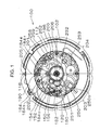
- Fig.1 is a plane view (back plane view) showing a state of viewing a movement in a state of releasing a mainspring from a side of a dial according to a first embodiment of a timepiece having a mainspring winding state display apparatus of the invention;
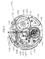
- Fig.2 is a plane view (top plane view) shoving a state of viewing the movement from a side of a case back according to the first embodiment of the timepiece having the mainspring winding state display apparatus of the invention;
- Fig.3 is a plane view (top plane view) showing a state of viewing the movement having removed a first bridge from the side of the case back according to the first embodiment of the timepiece having the mainspring winding state display apparatus of the invention;
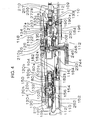
- Fig.4 is a partial sectional view showing a portion of the movement according to the first embodiment of the timepiece having the mainspring winding state display apparatus of the invention;
- Fig.5 is a plane view showing an outlook of a complete in a state in which the mainspring is wound back to a middle location according to the first embodiment of the timepiece having the mainspring winding state display apparatus of the invention;
- Fig.6 is a plane view (back plane view) showing a state of viewing a movement in a state in which a mainspring is release from a side of a dial according to a second embodiment of a timepiece having a mainspring winding state display apparatus of the invention;
- Fig.7 is a partial sectional view showing a portion of the movement according to the second embodiment of the timepiece having the mainspring winding state display apparatus of the invention;
- Fig.8 is a plane view showing an outlook of a complete in a state in which the mainspring is wound back to a middle location according to the second embodiment of the timepiece having the mainspring winding state display apparatus of the invention;
- Fig.9 is a plane view (back plane view) showing a state of viewing a movement in a state in which a mainspring is released froma side of a dial according to a third embodiment of a timepiece having a mainspring winding state display apparatus of the invention;
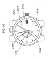
- Fig.10 is a plane view showing an outlook of a complete in a state in which the mainspring is wound back to a middle location according to the third embodiment of the timepiece having the mainspring winding state display apparatus of the invention;
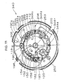
- Fig.11 is a plane view (back plane view) showing a state of viewing a movement in a state in which a mainspring is released from a side of a dial according to a fourth embodiment of a timepiece having a mainspring winding state display apparatus of the invention;
- Fig.12 is a partial sectional view showing a portion of the movement according to the fourth embodiment of the timepiece having the mainspring winding state display apparatus of the invention;
- Fig. 13 is a plane view (back plane view) showing a state of viewing a movement in a state in which a mainspring is released froma side of a dial according to a fifth embodiment of a timepiece having a mainspring winding state display apparatus of the invention;
- Fig.14 is a partial sectional view showing a portion of the movement according to the fifth embodiment of the timepiece having the mainspring winding state display apparatus of the invention;
- Fig. 15 is a plane view (back plane view) showing a state of viewing a movement in a state in which a mainspring is released froma side of a dial according to a sixth embodiment of a timepiece having a mainspring winding state display apparatus of the invention;
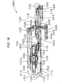
- Fig.16 is a partial sectional view showing a portion of the movement according to the sixth embodiment of the timepiece having the mainspring winding state display apparatus of the invention;
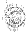
- Fig. 17 is a plane view (back plane view) showing a state of viewing a movement in a state in which a mainspring is released from a side of a dial according to a seventh embodiment of the timepiece having a mainspring winding state display apparatus of the invention;
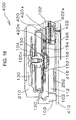
- Fig.18 is a partial sectional view showing a portion of the movement according to the seventh embodiment of the timepiece having the mainspring winding state display apparatus of the invention; and
- Fig.19 is a plane view showing an outlook of a complete in a state in which the mainspring is wound back to a middle location according to the seventh embodiment of the timepiece having the mainspring winding state display apparatus of the invention.
-
- An embodiment of a timepiece having a mainspring winding state display apparatus according to the invention will be explained in reference to the drawings as follows.
- First, an explanation will be given of a first embodiment of a timepiece having a mainspring winding state display apparatus according to the invention. In reference to Fig.1 through Fig.4, a timepiece having a mainspring winding state display apparatus of the invention is provided with a
movement 100. "Movement" indicates a machine body of the timepiece including a drive portion. Further, "complete" indicates a finished body of a timepiece in which a dial, indicators (hour hand, minute hand, second hand and the like) , a crown and the like are attached to the movement of the timepiece to be contained in a time case (timepiece exterior). Themovement 100 includes amain plate 102, a secondmain plate 112, and a dateindicator maintaining plate 116. In themovement 100, "top side" indicates a side of two faces of themain plate 102 remote from glass of the timepiece case, that is, "case back side". In themovement 100, "back side" indicates a side of the two faces of themain plate 102 proximate to the glass of the timepiece case, that is, "dial side". Themovement 100 further includes afirst bridge 104, asecond bridge 105, apallet fork bridge 106, and abalance bridge 107. The secondmain plate 112, and the dateindicator maintaining plate 116 are arranged on the back side of themain plate 102. Adial 110 is arranged on the side of the glass of the secondmain plate 112. Thedial 110 is attached to themain plate 102 via adial support ring 109. A hand setting stem 118 is integrated to themain plate 102 rotatably and movably in an axis line direction. - A top side of the
movement 100 is arranged with a top train wheel, an escaping mechanism, a speed control mechanism, an automatic winding mechanism, a hand winding mechanism, a switching apparatus, and a planetary mechanism for operating a mainspring winding state display mechanism. Alternatively, the hand winding mechanism may be deleted. Alternatively, the switching apparatus may be arranged on the back side of themovement 100. Alternatively, the hand winding mechanism may be arranged on the top side of themovement 100 and the automatic winding mechanism may be omitted. The back side of themovement 100 is arranged with a back train wheel, a date indicating mechanism, a date correcting mechanism, and a mainspring winding state display mechanism operated by a planetary mechanism. The top train wheel is roatatably supported by themain plate 102, thefirst bridge 104, and thesecond bridge 105. The back train wheel is rotatably supported by themain plate 102, the secondmain plate 112, and the dateindicator maintaining plate 116. Alternatively, the date indicating mechanism and the date correcting mechanism may be omitted. When needed, a day indicating mechanism and a day correcting mechanism may be provided on the back side of themovement 100. - In Fig. 1 and Fig. 2, a main plate reference
vertical axis line 205 passing arotational center 200 of anhour wheel 232 and substantially in parallel with a center axis line of thehand setting stem 118, and a main plate referencehorizontal axis line 206 passing therotational center 200 of thehour wheel 232 and orthogonal to the main plate referencevertical axis line 205 are defined at themain plate 102. Themain plate 102 is provided with afirst region 201 disposed on one side of the main plate referencevertical axis line 205 and disposed on a side of the main plate referencehorizontal axis line 206 proximate to thehand setting stem 118, asecond region 202 disposed on other side of the main plate referencevertical axis line 205 and disposed on a side of the main plate referencehorizontal axis line 206 proximate to thehand setting stem 118, athird region 203 disposed on other side of the main plate referencevertical axis line 205 where thesecond region 202 is present and disposed on a side of the main plate referencehorizontal axis line 206 remote from thehand setting stem 118, and afourth region 204 disposed on the one side of the main plate referencevertical axis line 205 where thefirst region 201 is present and disposed on a side of the main plate referencehorizontal axis line 206 remote from thehand setting stem 118. In Fig.1, although thefirst region 201 and thefourth region 204 are present on a right side of the main plate referencevertical axis line 205, thefirst region 201 and thefourth region 204 may be defined to be disposed on a left side of the main plate referencevertical axis line 205. In this case, thesecond region 202 and thethird region 203 are defined to dispose on a right side of the main plate referencevertical axis line 205. Further, according to the embodiment of the time piece having the mainspring winding state display apparatus of the invention, an arrangement of a part in the movement may be arranged as illustrated, or may be arranged to constitute line symmetry (mirror image) relative to the arrangement illustrated by constituting an axis of symmetry by the main plate referencevertical axis line 205. - Next, a constitution of a top train wheel will be explained. In reference to Fig.2 through Fig.4, the barrel complete 120 is rotatably supported by the
barrel bridge 104 and themain plate 102. The barrel complete 120 includes a mainspring 120b, abarrel stem 120c, abarrel gear 120d, and a barrel lid 120f. The mainspring 120b constitutes a power source of the mechanical timepiece. By winding back (releasing) the mainspring 120b, thebarrel gear 120d is rotated in one direction and indicates time information by indicators (hour hand, minute hand, second and the like) via rotation of the top train wheel and a back train wheel. Rotation of thebarrel gear 120d rotated by power of the mainspring 120b is controlled by a speed control apparatus and an escaping apparatus. The speed control apparatus includes a barrel withhairspring 142. The escaping apparatus includes apallet fork 144 and an escape wheel &pinion 146. The balance withhairspring 142 is rotatably supported by thebarrel bridge 107 and themain plate 102. Thepallet fork 144 is rotatably supported by thepallet fork bridge 106 and themain plate 102. The escape wheel &pinion 146 is rotatably supported by thefirst bridge 104 and themain plate 102. A center wheel &pinion 122 is constituted to be rotated by one rotation per hour by rotation of thebarrel gear 120d. The center wheel &pinion 122 is rotatably supported by thesecond bridge 105 and themain plate 102. A third wheel &pinion 124 is constituted to be rotated by rotation of the center wheel &pinion 122. - The third wheel and
pinion 124 is rotatably supported by thefirst bridge 104 and themain plate 102. A second wheel &pinion 126 is constituted to be rotated by one rotation per minute by rotation of the third wheel &pinion 124. The second wheel &pinion 126 is rotatably supported by thefirst bridge 104 and themain plate 102. A rotational speed of the second wheel &pinion 126 is constituted to be controlled by the escape wheel &pinion 146. A rotational speed of the escape wheel &pinion 146 is constituted to be controlled by thepallet fork 144. Pivoting movement of thepallet fork 144 is constituted to be controlled by the balance withhairspring 142. The top train wheel includes the center wheel &pinion 122, the third wheel &pinion 124 and the second wheel &pinion 126. Aminute hand 246 attached to the center wheel &pinion 122 is constituted to indicate "minute". Asecond hand 248 attached to the second wheel &pinion 126 is constituted to indicate "second". A rotational center of the second wheel &pinion 126 and a rotational center of the center wheel &pinion 122 are constituted to be disposed at the same position. A square hole portion of theratchet wheel 130 is integrated to asquare shaft portion 120h provided at an upper portion (a side of the first bridge 104) of thebarrel stem 120c of the barrel complete 120. Theratchet wheel 130 is supported to be rotated integrally with the barrel stem 20c by a squarehole stop screw 132. Theratchet wheel 130 can be rotated only in the same direction as a direction of rotating the barrel complete 120. Adetent 131 constituting a rotation rectifying member is provided at thefirst bridge 104 for rectifying rotation of theratchet wheel 130 only in one direction. Theratchet wheel 130 can be hampered from being rotated in a direction opposed to the direction of rotating the barrel complete 120 by thedetent 131. According to a constitution for providing a hand winding mechanism, the hand winding mechanism includes aclutch wheel 272, a windingpinion 133, acrown wheel 134 and a crown transmission wheel 135. The windingpinion 133 is constituted to be rotated by rotation of theclutch wheel 272 in one direction. The crown transmission wheel 135 is constituted to be rotated by rotation of the windingpinion 133 via rotation of thecrown wheel 134. Theratchet wheel 130 is constituted to be rotated in the clockwise direction by the rotation of the crown transmission wheel 135. The balance with hairspring 120b is constituted to be able to be wound by the rotation of theratchet wheel 130. - Next, a constitution of an automatic winding mechanism will be explained. In Fig.2 and Fig.4, an automatic winding mechanism for winding up the balance with hairspring 120b is provided on the top side of the
movement 100. The automatic winding mechanism includes anoscillating weight 210, afirst transmission wheel 212, apawl lever 214 and asecond transmission wheel 216. Theoscillating weight 210 is rotatably integrated to thefirst bridge 104 via aball bearing 210b. Thefirst transmission wheel 212 is rotatably supported by thefirst bridge 104 and themain plate 102. A gear portion of thefirst transmission wheel 212 is constituted to be brought in mesh with anoscillating weight pinion 210c of theoscillating weight 210. A hole (not illustrated) of a base portion of thepawl lever 214 is rotatably integrated to an eccentric cam portion (not illustrated) of thefirst transmission wheel 212. Thepawl lever 214 includes two pawl portions, that is, a pull pawl 214f and a push pawl 214g. Thesecond transmission wheel 216 is rotatably supported by thefirst bridge 104. The pull pawl 214f and the push pawl 214g of thepawl lever 214 are constituted to be brought in mesh with ratchet teeth (not illustrated) of thesecond transmission wheel 216. When theoscillating weight 210 is rotated, thepawl lever 214 is constituted to be operated by rotating thefirst transmission wheel 212. The pull pawl 214f of thepawl lever 214 is constituted to be able to rotate thesecond transmission wheel 216 only in one direction (counterclockwise direction in Fig. 2). The push pawl 214g of thepawl lever 214 is constituted to be able to rotate thesecond transmission wheel 216 only in one direction (counterclockwise direction in Fig.2). Therefore, when theoscillating weight 210 is rotated, thepawl lever 214 is operated, and theratchet wheel 130 is constituted to be rotated in the clockwise direction based on rotation of thesecond transmission wheel 216. As a result, when theoscillating weight 210 is rotated, the balance withhairspring 210b can be wound up by operating the automatic winding mechanism. - Next, a constitution of a back train wheel will be explained. In reference to Fig.4, a back train wheel includes a
minute wheel 230 and anhour wheel 232. Theminute wheel 230 is constituted to be rotated by rotation of the center wheel andpinion 122. Thehour wheel 232 is constituted to be rotated by one rotation per 12 hours by rotation of theminute wheel 230. Anhour hand 244 attached to thehour wheel 232 indicates "hour". A rotational center of thehour wheel 232 and a rotational center of the center wheel &pinion 122 are constituted to be disposed at the same position. It is preferable to arrange the rotational center of theminute wheel 230 on the main plate referencevertical axis line 205. - Next, a constitution of a switching mechanism will be explained. According to the timepiece of the invention, the switching mechanism and a time setting mechanism are provided in order to set time of the timepiece. In reference to Fig.3, the switching mechanism is constituted to include a setting
lever 236, ayoke 237 and ayoke holder 238. The time setting mechanism includes ahand setting stem 118 and aclutch wheel 272. The square hole portion of theclutch wheel 272 is integrated to the square shaft portion of thehand setting stem 118. A position of the hand setting stem 118 in a direction along a center axis line of the hand setting stem 118 is determined by a switching apparatus (setting lever, yoke and the like). A position of theclutch wheel 272 in the direction along the center axis line of the hand setting stem 118 is determined by the switching apparatus (setting lever, yoke, yoke holder and the like). Theclutch wheel 272 includes an A tooth 272a disposed on a side proximate to a center portion of themovement 100 and aB tooth 272b disposed on a side proximate to an outer shape portion of themovement 100. TheB tooth 272b of theclutch wheel 272 is constituted by a ratchet gear. The windingpinion 133 includes a windingsmall gear 133b constituted to be able to be brought in mesh with theB tooth 272b of theclutch wheel 272 and a winding large gear 133c constituted to be able to be brought in mesh with a gear portion of thecrown wheel 134. The windingsmall gear 133b is constituted by a ratchet gear. - In a state of setting the hand setting stem 118 to 0 stage and in a state of setting the hand setting stem 118 to 1 stage, the A tooth 272a of the
clutch wheel 272 is constituted not to be brought in mesh with the gear portion of theminute wheel 230. In the state of setting the hand setting stem 118 to 0 stage and in the state of setting the hand setting stem 118 to 1 stage, theB tooth 272b of theclutch wheel 272 is constituted to be brought in mesh with thesmall gear 133b of the windingpinion 133. In a state of setting the hand setting stem 118 to 2 stage, the A tooth 272a of theclutch wheel 272 is constituted to be brought in mesh with the gear portion of thehour wheel 230. In the state of setting the hand setting stem 118 to 2 stage, the A tooth 272a of theclutch wheel 272 is constituted not to be brought in mesh with thesmall gear 133b of the windingpinion 133. When the hand setting stem 118 is rotated in one direction in the state of setting the hand setting stem 118 to 0 stage, the mainspring 120b is constituted to be able to be wound up by rotating theclutch wheel 272 along with thehand setting stem 118 and rotating theratchet wheel 130 via rotation of the windingpinion 133, thecrown wheel 134 and the crown transmission wheel 135. When the hand setting stem 118 is rotated in other direction in the state of setting the hand stetting stem 118 to 0 stage, although theclutch wheel 272 is rotated along with thehand setting stem 118, the windingpinion 133 is constituted not to be rotated. (1 · 6) Constitution of a calendar mechanism - Next, a constitution of a calendar mechanism will be explained. According to the timepiece having a calendar, a date indicator feeding mechanism is constituted to be operated based on rotation of the back train wheel. The date indicator feeding mechanism includes a date
indicator driving wheel 250, an intermediate dateindicator driving wheel 251 and adate indicator 252. The intermediate dateindicator driving wheel 251 is constituted to be rotated by rotation of thehour wheel 232. The dateindicator driving wheel 250 is constituted to be rotated by rotation of the intermediate dateindicator driving wheel 251. Thedate indicator 252 is constituted to be rotated by (1/31) once per day by adate feeding pawl 250b provided at the dateindicator driving wheel 250. Thedate indicator 252 is constituted to be rotated by one rotation per 31 days. A position in a rotational direction of thedate indicator 252 is rectified by adate jumper 253.Date characters 252c from "1" to "31" provided at thedate indicator 252 are constituted to indicate "date" (refer to Fig.5). - Next, a constitution of a date correcting mechanism will be explained. The timepiece of the invention can be provided with a date correcting mechanism for correcting display of date by the
date indicator 252. In reference to Fig.1 and Fig.4, the date correcting mechanism is constituted by theclutch wheel 272, the windingpinion 133, a first correctortransmission setting wheel 257, a first correctortransmission setting wheel 258 and acorrector setting wheel 259. When the hand setting stem 118 is rotated in one direction in a state of setting the hand setting stem 118 to 1 stage, theclutch wheel 272 is rotated, thecorrector setting wheel 259 is pivoted in one direction to stop at a first position via rotation of the windingpinion 133 and the first correctortransmission setting wheel 257, and is constituted to be able to rotate thedate indicator 252 by rotating thecorrector setting wheel 259 at the first position. Thedate indicator 252 is constituted not to be able to be rotated even when the hand setting stem 118 is rotated in other direction in the state of setting the hand setting stem 118 to 1 stage. - Next, a constitution of a mainspring winding state display mechanism will be explained. The mainspring winding state display mechanism includes a planetary mechanism. In reference to Fig. 1 and Fig. 4, the planetary mechanism constitutes a speed reducing mechanism cooperatively moved with a
barrel gear 120d for reducing the speed of rotation of thebarrel gear 120d. The planetary mechanism includes afirst sun wheel 150, a firstplanetary wheel 152, a secondplanetary wheel 154 and asecond sun wheel 156. Thefirst sun wheel 150 is fixed to alower shaft portion 120h provided at a lower middle portion of abarrel stem 120c of the barrel complete 120, portion on a side of themain plate 102 and on a side most proximate to a bottom face of thebarrel gear 120d. The firstplanetary wheel 152 is attached rotatably to the bottom face of thebarrel gear 120d. The secondplanetary wheel 154 is rotatably attached to the bottom face of thebarrel gear 120d. Thesecond sun wheel 156 is rotatably attached to a lower front end shaft portion of thebarrel stem 120c of the barrel complete 120 (portion mostly proximate to the main plate 102). Thefirst sun wheel 150 is constituted to be brought in mesh with the firstplanetary wheel 152. The firstplanetary wheel 152 is constituted to be brought in mesh with the secondplanetary wheel 154. The secondplanetary wheel 154 is constituted to be brought in mesh with thesecond sun wheel 156. When thebarrel gear 120d is rotated, the firstplanetary wheel 152 is constituted to be able to be rotated while revolving around thefirst sun wheel 150. When thebarrel gear 120d is rotated, the secondplanetary wheel 154 is constituted to be able to be rotated while revolving around thefirst sun wheel 150. It is preferable to arrange a rotational center of thefirst sun wheel 150 at thesecond region 202. - A first winding mark
intermediate wheel 180 is rotatably supported by themain plate 102 and the dateindicator maintaining plate 116. The first winding markintermediate wheel 180 includes a first winding mark intermediate gear 180a and a first winding mark intermediate pinion 180b. It is preferable to arrange a rotational center of the first winding markintermediate wheel 180 at thethird region 203. A second winding markintermediate wheel 182 is rotatably supported by the secondmain plate 112 and the dateindicator maintaining plate 116. The second winding markintermediate wheel 182 includes a second winding mark intermediate gear 182a and a second winding markintermediate pinion 182b. It is preferable that a rotational center of the second winding markintermediate wheel 182 is arranged at thethird region 203. A windingmark drive wheel 184 is rotatably supported by the secondmain plate 112. The windingmark drive wheel 184 is arranged between the secondmain plate 112 and the dateindicator maintaining plate 116. The windingmark drive wheel 184 includes afirst segment portion 184b and a second segment portion 184f. Afirst segment gear 184c is provided at thefirst segment portion 184b. A second segment 184g is provided at the second segment portion 184f. It is preferable to constitute an outer diameter (pitch diameter) of thefirst segment gear 184c to be a dimension larger than an outer diameter (pitch diameter) of the second segment gear 184g. It is preferable that an opening angle of thefirst segment gear 184c is about 25 degrees. It is preferable that an opening angle of the second segment gear 184g is about 50 degrees. The windingmark drive wheel 184 constitutes a "deformed segment gear" having the two segment gears having the different outer diameters (pitch diameters). Thefirst segment gear 184c is constituted to be brought in mesh with the second winding mark intermediate gear 182a. - A winding
mark indicator 190 is rotatably supported by the secondmain plate 112 and the dateindicator maintaining plate 116. The windingmark indicator 190 includes a winding mark gear 190a. The winding mark gear 190a is constituted to be brought in mesh with the second segment gear 184g. A rotational center of the windingmark indicator 190 is arranged at a region on the main plate referencevertical axis line 205 and on a side proximate to the hand setting stem 118 (3 o'clock direction of the dial 110). It is preferable that a rotational center of the windingmark driving wheel 184 is arranged in a region on the main plate referencevertical axis line 205 and proximate to thehand setting stem 118. It is preferable that a rotational center of the windingmark drive wheel 184 is arranged at a region between the rotational center of the windingmark indicator 190 and a rotational center of thehour wheel 232. A windingmark hand 196 constituting a mainspring winding state display member is attached to a winding mark indicator stem of the windingmark indicator 190. When a mainspring winding state is intended to display by constituting a rotational center by a position in 3 o'clock direction of thedial 110 in themovement 100, the windingstem hand 196 constituting the main spring winding state display member is attached to the winding mark indicator stem of the windingmark indicator 190. According to the constitution, in reference to Fig.5, a display sign 110a indicating a mainspring winding state is provided at thedial 110. For example, the display sign 110a includes numerals of "0", "20", "40", "60". The user can know a state of winding the mainspring by a position of a front end of the windingmark hand 196 and the display sign 110a. By the constitution, the rotational center of the winding mark hand 196 (that is, rotational center of power reserve indicator) can be arranged at an arbitrary pertinent position in themovement 100 of the timepiece regardless of a position of the rotational center of thebarrel gear 120d. Further, by the constitution, an influence of backlashes of mesh among the gears for transmitting rotation to the windingmark hand 196 can be reduced and operation of the windingmark hand 196 can effectively be prevented from being retarded. - In reference to Fig.1 through Fig.4, in a state of completely winding back the mainspring 120b, by rotating the automatic winding train wheel, the
ratchet wheel 130 is rotated in the clockwise direction. Under the state, rotation of thebarrel gear 120d is rectified by the center wheel &pinion 122. Under the state, thebarrel stem 120 and thefirst sun wheel 150 are rotated by rotation of theratchet wheel 130. The firstplanetary wheel 152 is rotated (only rotation) by rotation of thefirst sun wheel 150. The secondplanetary wheel 154 is rotated (only rotation) by rotation of thefirst sun wheel 152. Thesecond sun wheel 156 is rotated by rotation of the secondplanetary wheel 154. The first winding markintermediate wheel 180 is rotated by rotation of thesecond sun wheel 156. The second winding markintermediate wheel 182 is rotated by rotation of the first winding markintermediate wheel 180. The windingmark drive wheel 184 is rotated by rotation of the second winding markintermediate wheel 182. The windingmark indicator 190 is rotated in the clockwise direction by rotation of the windingmark drive wheel 184. - Therefore, as winding up the mainspring 120b, the winding
mark hand 196 is rotated in the clockwise direction, the windingmark hand 196 is brought into a state of indicating "60" of the display sign 110a from a state of indicating "0" of the display sign 110a by the windingmark hand 196, via a state of indicating "20" of the display sign 110a by the windingmark hand 196, further, via a state of indicating "40" by the windingmark hand 196. A state shown in Fig. 5 indicates a state in which the windingmark hand 196 slightly passes a state of "2/3 winding" of the mainspring. In the case of the hand winding timepiece, the mainspring cannot be wound up more than a state of "full winding" by the mainspring. Meanwhile, in the case of the automatic winding timepiece, when the mainspring is going to be wound up more than a state of "full winding" of the mainspring, a portion of a slipping attachment (not illustrated) provided in the barrel complete 120 is slipped. In a state in which the slipping attachment is slipped, by bringing the windingmark indicator 190 into contact with a winding mark indicator degree determining pin (not illustrated) , the windinghand 196 can be hampered from being rotated further in the counterclockwise direction. - In reference to Fig. 1 through Fig. 4, in a state of winding up the mainspring, time is indicated by rotating the
barrel gear 120d. Under the state, thebarrel gear 120d is rotated in the clockwise direction. Under the state, rotation of theratchet wheel 130 is rectified by operation of thedetent 131 engaged with teeth of theratchet wheel 130. Therefore, thefirst sun wheel 150 constitutes "fixed gear" in the planetary gear mechanism. By rotation of thebarrel gear 120d, the firstplanetary wheel 152 and the secondplanetary wheel 154 execute "planetarymovement" in which the rotational centers are varied. By the planetary movement of the firstplanetary wheel 152 and the secondplanetary wheel 154, the secondplanetary wheel 156 is rotated. The first winding markintermediate wheel 180 is rotated by rotation of thesecond sun wheel 156. The second winding markintermediate wheel 182 is rotated by rotation of the first winding markintermediate wheel 180. The windingmark drive wheel 184 is rotated by rotation of the second winding markintermediate wheel 182. The windingmark display wheel 190 is rotated in the counterclockwise direction by rotation of the windingmark drive wheel 184. Therefore, as winding back (releasing) the mainspring 120b by rotating the barrel complete 120, the windingmark hand 196 is rotated in the counterclockwise direction at a speed lower than a normal rotational speed of the train wheel. Therefore, the windingmark hand 196 is brought into the state of indicating "0" of the display sign 110a from the state of indicating "60" of the display sign 110a by the windingmark hand 196, via the state of indicating "40" of the display sign 110a by the windingmark hand 196 and via a state of bringing the windingmark hand 196 into the state of indicating "20" of the display sign 110a. - For example, when the winding
mark 196 indicates "20", it is shown that a duration is 20 hours, when the windingmark 196 indicates "40", it is shown that the duration is 40 hours, and when the windingmark 196 indicates "60", it is shown that the duration is 60 hours. The display sign 110a may be constituted to indicate a "full winding" state of the mainspring by "1", indicate a "half winding" state of the mainspring by "1/2" and indicate a "release" state of the mainspring by "0". Further, the display sign 110a may be constituted to indicate the "full winding" state of the mainspring by "100 %", indicate the "half winding" state of the mainspring by "50 %" and indicate the "release" state of the mainspring by "0 %". Alternately, the display sign 110a may be constituted to indicate the "full winding" state of the mainspring by "black circle sign", indicate the "half winding" state of the mainspring by "semicircle sign" and indicate the "release" state of the mainspring by "white circle sign". - In reference to Fig. 5, a complete of the timepiece having the mainspring winding state display apparatus of the invention includes a
timepiece case 290.Themovement 100 of the timepiece having the mainspring winding state display apparatus is contained in thetimepiece case 290. "Hour" of the current time is indicated by thehour hand 244. "Minute" of the current time is indicated by theminute hand 246. "Second" of the current time is indicated by thesecond hand 248. Current "date" is indicated by thedate character 252c provided at thedate indicator 252. The display sign 110a provided at thedial 110 indicates the duration capable of operating the timepiece having the mainspring winding state display apparatus. In Fig. 5, the windingmark hand 196 indicates a position of slightly passing "40" of the display sign 110a. The state shows that the duration of the mainspring is equal to or longer than 40 hours. An angle of rotating the windingmark hand 196 from the "full winding" state of the mainspring is constituted to correspond to the duration of the timepiece. As has been explained above, according to the timepiece having the mainspring winding state display apparatus of the invention, the duration of the timepiece can be indicated very comprehensively. - Next, a second embodiment of a timepiece having a mainspring winding state display apparatus of the invention will be explained. In the following explanation, a description will mainly be given of points of the second embodiment of the timepiece having the mainspring winding state display apparatus of the invention different from the first embodiment of the timepiece having the mainspring winding state display apparatus of the invention. Therefore, the above-described explanation of the first embodiment of the timepiece having the mainspring winding state display apparatus will be applied to a portion which is not described in the following. In reference to Fig. 6 through Fig.8, according to the second embodiment of the timepiece having the mainspring winding state display apparatus of the invention, in a
movement 320 of the timepiece having the mainspring winding state display apparatus, the rotational center of the windingmark display wheel 190 is arranged in a region on the main plate referencehorizontal axis line 206 in 6 o'clock direction of thedial 110. A windingmark drive wheel 324 is rotatably supported by the secondmain plate 112. It is preferable that a rotational center of the windingmark drive wheel 324 is arranged at a region on the main plate referencevertical axis line 205 in 3 o'clock direction of thedial 110. It is preferable that the rotational center of the windingmark drive wheel 324 is arranged at a region between a rotational center of the windingmark display wheel 190 and a rotational center of thehour wheel 232. The windingmark drive wheel 324 includes afirst segment portion 324b and a second segment portion 324f. Afirst segment gear 324c is provided at thefirst segment portion 324b. It is preferable to constitute an outer diameter (pitch diameter) of thefirst segment gear 324c to be a dimension substantially the same as an outer diameter (pitch diameter) of a second segment gear 324g. The outer diameter (pitch diameter) of thefirst segment gear 324c may be constituted to differ from the outer diameter (pitch diameter) of the second segment gear 324g. It is preferable that an opening angle of thefirst segment gear 324c is about 25 degrees. The second segment gear 324g is provided at the second segment portion 324f. It is preferable that an opening angle of the second segment gear 324g is about 60 degrees. - The winding
mark drive wheel 324 constitutes "deformed segment gear" including the two segment gears. Thefirst segment gear 324c is constituted to be brought in mesh with the second winding mark intermediate gear 182a. The windingmark indicator 190 is rotatably supported by the secondmain plate 112 and the dateindicator maintaining plate 116. The windingmark indicator 190 includes a winding mark gear 190a. The second segment gear 324g is constituted to be brought in mesh with the winding mark gear 190a. By the constitution, a rotational center of the winding mark hand 196 (that is, rotational center of a power reserve indicator) can be arranged at an arbitrary pertinent position in the movement of the timepiece regardless of the position of the rotational center of thebarrel gear 120d. Further, by the constitution, an influence of backlashes of mesh among gears for transmitting rotation to the windingmark hand 196 can be reduced, and operation of the windingmark hand 196 can effectively be prevented from being retarded. The secondmain plate 112, thedate indicator holder 116, and the windingmark indicator 190 are constituted to be able to integrate the windingmark display wheel 190 at a plurality of positions to be able to be applied to both the first embodiment and the second embodiment of the timepiece having the mainspring winding state display apparatus of the invention. It is preferable to constitute the secondmain plate 112 to be able to integrate the windingmark indicator 190 at other position so as to be able to be applied also to a constitution for providing the windingmark indicator 190 at other position. According to the invention, the mainspring winding state can be displayed by the windingmark hand 196 by constituting the rotational center by a plurality of positions by using the single movement and therefore, timepieces having a plurality of designs can easily be realized. - In reference to Fig.8, the
movement 320 of the timepiece having the mainspring winding state display apparatus is contained in thetimepiece case 290. A display sign 328a provided at adial 328 indicates a duration capable of operating the timepiece having the mainspring winding state display apparatus. In Fig.8, the windingmark hand 196 indicates a position of slightly passing "40" of the display sign 328a. As has been explained above, according to the timepiece having the mainspring winding state display apparatus of the invention, the duration of the timepiece can be displayed very comprehensively. - Next, a third embodiment of a timepiece having a mainspring winding state display apparatus of the invention will be explained. In the following explanation, a description will mainly be given of points of the third embodiment of the timepiece having the mainspring winding state display apparatus of the invention different from the first embodiment of the timepiece having the mainspring winding state display apparatus of the invention. Therefore, the above-described explanation of the first embodiment of the timepiece having the mainspring winding state display apparatus of the invention will be applied to a portion which is not described in the following. In reference to Fig.9 and Fig.10, according to the third embodiment of the timepiece having the mainspring winding state display apparatus of the invention, in a
movement 330 of the timepiece having the mainspring winding state display apparatus, the rotational center of the windingmark indicator 190 is arranged at a region on the main plate referencevertical axis line 205 and in 9 o' clock direction of thedial 110. A windingmark drive wheel 334 is rotatably supported by the secondmain plate 112. It is preferable that a rotational center of the windingmark drive wheel 334 is arranged at a region on the main plate referencevertical axis line 205 and in 3 o'clock direction of thedial 110. It is preferable that the rotational center of the windingmark drive wheel 324 is arranged at a region between the rotational center of the windingmark indicator 190 and the rotational center of thehour wheel 232. The windingmark drive wheel 324 includes afirst segment portion 324b and a second segment portion 324f. Afirst segment gear 324c is provided at thefirst segment portion 324b. A second segment gear 324g is provided at the second segment portion 324f. It is preferable to constitute the outer diameter (pitch diameter) of thefirst segment gear 324c to be a dimension substantially the same as the outer diameter (pitch diameter) of the second segment gear 324g. The outer diameter (pitch diameter) of thefirst segment gear 324c may be constituted to differ from the outer diameter (pitch diameter) of the second segment gear 324g. It is preferable that the opening angle of thefirst segment gear 324c is about 25 degrees. It is preferable that the opening angle of the second segment gear 324g is about 60 degrees. - A winding mark
drive transmission wheel 336 is rotatably supported by the secondmain plate 112. A gear portion of the winding markdrive transmission wheel 336 is constituted to be brought in mesh with the second segment gear 324g. The winding mark gear 190a is constituted to be brought in mesh with the gear portion of the winding markdrive transmission wheel 336. The windingmark indicator 190 is rotatably supported by the secondmain plate 112 and the dateindicator maintaining plate 116. The windingmark indicator 190 includes the winding mark gear 190a. The winding mark gear 190a is constituted to be brought in mesh with the second segment gear 324g. Thesecondmain plate 112, the dateindicator maintaining plate 116, the windingmark drive wheel 324 and the windingmark indicator 190 are constituted to be able to integrate the same windingmark indicator 190 in plural positions in order to be able to be applied to both the second embodiment and the third embodiment of the timepiece having the main plate winding state display apparatus of the invention. It is preferable that thesecondmain plate 112 and the dateindicator maintaining plate 116 are constituted to be able to integrate the windingmark indicator 190 at other position to be able to be applied also to a constitution for providing the windingmark indicator 190 at other position. - In a state of completely winding back the mainspring 120b, when the
ratchet wheel 130 is rotated in the clockwise direction by rotation of the automatic winding train wheel, the first winding markintermediate wheel 180 is rotated via operation of the planetary mechanism. The second winding markintermediate wheel 182 is rotated by rotation of the first winding markintermediate wheel 180. The windingmark drive wheel 334 is rotated by rotation of the second winding markintermediate wheel 182. The winding markdrive transmission wheel 336 is rotated by rotation of the windingmark drive wheel 184. The windingmark indicator 190 is rotated in the counterclockwise direction by rotation of the winding markdrive transmission wheel 336. In a state of winding up the mainspring, the first winding markintermediate wheel 180 is rotated by rotation of thebarrel gear 120d via operation of the planetary mechanism. The second winding markintermediate wheel 182 is rotated by rotation of the first winding markintermediate wheel 180. The windingmark drive wheel 184 is rotated by rotation of the second winding markintermediate wheel 182. The winding markdrive transmission wheel 336 is rotated by rotation of the windingmark drive wheel 184. The windingmark indicator 190 is rotated in the clockwise direction by rotation of the winding markdrive transmission wheel 336. Therefore, as winding back (releasing) the mainspring 120b by rotating the barrel complete 120, the windingmark hand 196 is rotated in the clockwise direction at a speed slower than a normal rotational speed of the train wheel. - The winding
mark drive wheel 334 constitutes "deformed segment gear" having two segment gears having the outer diameters (pitch diameters) of substantially the same dimension. By the constitution, the rotational center of the winding mark hand 196 (that is, rotational center of the power reserve indicator) can be arranged at an arbitrary pertinent position in the movement of the timepiece regardless of the position of the rotational center of thebarrel gear 120d. Further, by the constitution, an influence of backlashes of mesh among gears for transmitting rotation to the windingmark hand 196 can be reduced and operation of the windingmark hand 196 can effectively be prevented from being retarded. Therefore, according to the invention, by using the single movement, the mainspring winding state can be displayed by constituting the rotational center by a plurality of positions and therefore, timepieces having a plurality of designs can easily be realized. In reference to Fig.10, themovement 330 of the timepiece having the mainspring winding state display apparatus is contained in thetimepiece case 290. A display sign 338a provided at adial 338 indicates a duration capable of operating the timepiece having the mainspring winding state display apparatus. In Fig.10, the windinghand 196 indicates a position slightly passing "40" of the display sign 338a. As has been explained above, according to the timepiece having the mainspring winding state display apparatus of the invention, the duration of the timepiece can be displayed very comprehensively. - Next, a fourth embodiment of a timepiece having a mainspring winding state display apparatus of the invention will be explained. In the following explanation, a description will mainly be given of points of the fourth embodiment of the timepiece having the mainspring winding state display apparatus of the invention different from the first embodiment of the timepiece having the mainspring winding state display apparatus of the invention. Therefore, the above-described explanation of the first embodiment of the timepiece having the mainspring winding state display apparatus will be applied to a portion which is not described in the following. In reference to Fig.11 and Fig. 12, according to the fourth embodiment of the timepiece having the mainspring winding state display apparatus of the invention, in a
movement 340 of the timepiece having the mainspring winding state display apparatus, the rotational center of the windingdisplay wheel 190 is arranged in a region on the main plate referencevertical axis line 205 and in 3 o'clock direction of thedial 110. A windingmark drive wheel 344 is rotatably supported by the secondmain plate 112. It is preferable that a rotational center of the windingmark drive wheel 344 is arranged at the same position as therotational center 200 of thehour wheel 232. The windingmark drive wheel 344 includes a first segment portion 344a, asecond segment portion 344c and athird segment portion 344f. The first segment portion 344a is arranged at a region between substantially 12 o' clock direction and substantially 4 o'clock direction of thedial 110. Thesecond segment portion 344c is arranged at a region between substantially 6 o'clock direction and substantially 7 o'clock direction of thedial 110. Thethird segment portion 344f is arranged at a region between substantially 9 o'clock direction and substantially 10 o'clock direction of thedial 110. - A
first segment gear 344b is provided at the first segment portion 344a. Asecond segment gear 344d are provided at thesecond segment portion 344c. A third segment gear 344g is provided at thesegment portion 344f. It is preferable to constitute such that an outer diameter (pitch diameter) of thefirst segment gear 344b, an outer diameter (pitch diameter) of thesecond segment gear 344d and an outer diameter (pitch diameter) of the third segment gear 344g are constituted by the same dimension. It is preferable that an opening angle of the first segment gear 344a is about 130 degrees. It is preferable that an opening angle of thesecond segment gear 344d is about 40 degrees. It is preferable that an opening angle of the third segment gear 344g is about 40 degrees. A portion of thefirst segment gear 344b is constituted to be brought in mesh with the second winding mark intermediate gear 182a. Other portion of thefirst segment gear 344b is constituted to be brought in mesh with the winding mark gear 190a. - The winding
mark drive wheel 344 constitutes "deformed segment gear" having the three segment gears having the outer diameters (pitch diameters) of the same dimension. The windingmark drive wheel 344 is constituted by the "deformed segment gear" because it is necessary to avoid the first corrector settingtransmission wheel 257, the first corrector settingtransmission wheel 258, the dateindicator driving wheel 250 and thedate jumper 253. Thefirst segment gear 344b is constituted to be brought in mesh with the second winding mark intermediate gear 182a. The first segment gear 340b is constituted to be brought in mesh with winding mark gear 190a. By the constitution, the rotational center of the winding mark hand 196 (that is, rotational center of the power reserve indicator) can be arranged at an arbitrary pertinent position in the movement of the timepiece regardless of the position of the rotational center of thebarrel gear 120d. Further, by the constitution, an influence of backlashes of mesh among gears for transmitting rotation to the windingmark hand 196 can be reduced and operation of the windingmark hand 196 can effectively be prevented from being retarded. For example, the secondmain plate 112 is constituted to be able to integrate the windingmark drive wheel 344 at least at positions of 3 portions to be able to be applied to any of the fourth embodiment, the fifth embodiment and the sixth embodiment of the timepiece having the main plate winding state display apparatus of the invention. The secondmain plate 112, the dateindicator maintaining plate 116, the windingmark drive wheel 344, and the windingmark indicator 190 are constituted to be able to integrate the same windingmark indicator 190 at a plurality of positions to be able to be applied to any of the fourth embodiment, the fifth embodiment and the sixth embodiment of the timepiece having the mainspring winding state display apparatus of the invention. It is preferable to constitute the secondmain plate 112 and the dateindicator maintaining plate 116 to be able to integrate the windingmark indicator 190 at other position to be able to be applied to also a constitution for providing the windingmark indicator 190 at other position. According to the invention, by using the single movement, the main plate winding state can be displayed by constituting the rotational center by a plurality of positions and therefore, timepieces having a plurality of designs can easily be realized. - Next, a fifth embodiment of a timepiece having a mainspring winding state display apparatus of the invention will be explained. In the following explanation, a description will mainly be given of points of the fifth embodiment of the timepiece having the mainspring winding state display apparatus of the invention different from the fourth embodiment of the timepiece having the mainspring winding state display apparatus of the invention. Therefore, the above-described explanation of the first embodiment of the timepiece having the mainspring winding state display apparatus and the fourth embodiment of the timepiece having the mainspring winding state display apparatus will be applied to a portion which is not described in the following. In reference to Fig.13 and Fig.14, according to the fifth embodiment of the timepiece having the mainspring winding state display apparatus of the invention, in a
movement 350 of the timepiece having the mainspring winding state display apparatus, the rotational center of the windingmark indicator 190 is arranged at a region on the main plate referencehorizontal axis line 206 and in 6 o'clock direction of thedial 110. The windingmark drive wheel 344 is rotatably supported by the secondmain plate 112. It is preferable that the rotational center of the windingmark drive wheel 344 is arranged at the same position as that of therotational center 200 of thehour wheel 232. Thefirst segment gear 344b is constituted to be brought in mesh with the second winding mark intermediate gear 182a. Thesecond segment gear 344d is constituted to be brought in mesh with the winding mark gear 190a. By the constitution, the rotational center of the winding hand 196 (that is, rotational center of the power reserve indicator) can be arranged at an arbitrary pertinent position in the movement of the timepiece regardless of the position of the rotational center of thebarrel gear 120d. Further, by the constitution, an influence of backlashes of mesh among gears for transmitting rotation to the windingmark hand 196 can be reduced and operation of the windingmark hand 196 can effectively be prevented from being retarded. - Next, a sixth embodiment of a timepiece having a mainspring winding state display apparatus of the invention will be explained. In the following explanation, a description will mainly be given of points of the sixth embodiment of the timepiece having the mainspring winding state display apparatus of the invention different from the fourth embodiment of the timepiece having the mainspring winding state display apparatus of the invention. Therefore, the above-described explanation of the first embodiment of the timepiece having the mainspring winding state display apparatus of the invention and the above-described explanation of the fourth embodiment of the timepiece having the mainspring winding state display apparatus of the invention will be applied to a portion which is not described in the following. In reference to Fig.15 and Fig.16, according to the sixth embodiment of the timepiece having the mainspring winding state display apparatus of the invention, in a
movement 360 of the timepiece having the mainspring winding state display apparatus, the rotational center of the windingmark indicator 190 is arranged at a region on the main plate referencevertical axis line 205 and in 9 o'clock direction of thedial 110. The windingmark drive wheel 344 is roatably supported by the secondmain plate 112. It is preferable to arrange the rotational center of the windingmark drive wheel 344 at the same position as therotational center 200 of thehour wheel 232. Thefirst segment gear 344b is constituted to be brought in mesh with the second winding mark intermediate gear 182a. The third segment gear 344g is constituted to be brought in mesh with the winding mark gear 190a. By the constitution, the rotational center of the winding mark hand 196 (that is, rotational center of the power reserve indicator) can be arranged at an arbitrary pertinent position in the movement of the timepiece regardless of the position of the rotational center of thebarrel gear 120d. Further, by the constitution, an influence of backlashes of mesh among gears for transmitting rotation to the windingmark hand 196 can be reduced and operation of the windingmark hand 196 can effectively be prevented from being retarded. - Next, a seventh embodiment of a timepiece having a mainspring winding state display apparatus of the invention will be explained. In the following explanation, a description will mainly be given of points of the seventh embodiment of the timepiece having the mainspring winding state display apparatus of the invention different from the first embodiment of the timepiece having the mainspring winding state display apparatus of the invention. Therefore, the above-described explanation of the first embodiment of the timepiece having the mainspring winding state display apparatus of the invention will be applied to a portion which is not described in the following. In reference to Fig.17 and Fig.18, according to the seventh embodiment of the timepiece having the mainspring winding state display apparatus of the invention, a
dial 410 is attached to themain plate 102 via a dial support ring 409. The winding markintermediate wheel 420 is rotatably supported by themain plate 120 and a dateindicator maintaining plate 416. A winding markintermediate wheel 420 includes a winding mark intermediate gear 420a and a winding markintermediate pinion 420b. The wining mark intermediate gear 420a is constituted to be brought in mesh with thesecond sun gear 150. It is preferable to arrange a rotational center of the winding markintermediate wheel 420 at thethird region 203. A windingmark indicator 422 is rotatably supported by a secondmain plate 412 and the dateindicator maintaining plate 416. The windingmark indicator 422 includes a winding mark gear 422a. The winding mark gear 422a is constituted to be brought in mesh with the winding markintermediate wheel 420. A rotational center of the windingmark indicator 422 is arranged at a region on the main plate referencehorizontal axis line 206 and in 12 o'clock direction of thedial 410. The windingmark hand 196 constituting the main plate winding state display member is attached to a winding mark indicator stem of the windingmark indicator 422. According to the constitution, in reference to Fig.19, a display sign 410a indicating the mainspring winding state is provided at thedial 410. For example, the display sign 110a includes numerals of "0", "20", "40", "60". A user can know the state of winding the mainspring by a position of a front end of the windingmark hand 196 and the display sign 410a. - In the state of completely winding back the mainspring 120b, when the
ratchet wheel 130 is rotated in the clockwise direction by rotation of the automatic winding train wheel, the winding markintermediate wheel 420 is rotated via operation of the planetary mechanism. The windingmark indicator 190 is rotated in the clockwise direction by rotation of the winding markintermediate wheel 420. In the state of winding up the mainspring, the winding markintermediate wheel 420 is rotated via operation of the planetary mechanism by rotation of thebarrel gear 120d. The windingmark indicator 190 is rotated in the counterclockwise direction by rotation of the winding markintermediate wheel 420. Therefore, as winding back (releasing) the mainspring 120b by rotating the barrel complete 120, the windingmark hand 196 is rotated in the counterclockwise direction at a speed lower than a normal rotational speed of the train wheel. As has been explained above, according to the timepiece having the mainspring winding state display apparatus of the invention, the duration of the timepiece can be displayed very comprehensively. - The first example of the timepiece having the mainspring winding state display apparatus of the invention can be constituted by the following condition as an example.
the number of teeth of thebarrel gear 120d: 84
the number of teeth of the ratchet wheel 130: 62
the number of teeth of the first sun wheel 150: 20
the number of teeth of the first planetary wheel 152: 24
the number of teeth of the gear of the second planetary wheel 154: 20
the number of teeth of the pinion of the second planetary wheel 154: 12
the number of teeth of the gear of the first winding mark intermediate wheel 180 : 48
the number of teeth of the pinion of the first winding mark intermediate wheel 180 : 8
the number of teeth of the second sun wheel 156: 24
the number of teeth of thefirst segment gear 184c (a calculated value when teeth are present over an entire periphery): 200
the number of teeth of the second segment gear 184g (a calculated value when teeth are present over an entire periphery) : 104
the number of teeth of the winding mark indicator 190 : 13 - According to the constitution, a speed reducing ratio from the
barrel gear 120d to the windingmark indicator 190 is 1/18. Further, when the number of winding of the mainspring is 6 turns, theindicator 196 attached to the windingmark indicator 190 can be moved by 120 degrees. Further, when the number of winding of the mainspring is 7 turns, theindicator 196 attached to the windingmark indicator 190 can be moved by 140 degrees. - Further, according to the timepiece having the mainspring winding state display apparatus of the invention, by changing the above-described numbers of teeth of the gears, a content of display of the mainspring winding state can be changed. Further, by changing the above-described speed reducing ratio, the angle of the rotation of rotating the winding
mark hand 196 based on rotation of thebarrel gear 120d can be changed. For example, according to a constitution of making the speed reducing ratio from thebarrel gear 120d to the windingmark indicator 190 1/18 when the same mainspring as that used in the above-described embodiments of the invention is used, the angle of the rotation of the windingmark indicator 190 in correspondence with from the state of releasing the spring to the fully winding state can be set to about 90 degrees. - The invention is applicable to the constitution of arranging the mainspring winding state display member (power reserve indicator) at an arbitrary pertinent position in the movement of the timepiece in the timepiece having the mainspring winding state display apparatus having the function of displaying the state of winding of the mainspring constituting the power source of the mechanical timepiece. That is, according to the invention, in the timepiece having the mainspring winding state display apparatus, the rotational center of the winding mark hand can be arranged at an arbitrary pertinent position in the movement of the timepiece regardless of the position of the rotational center of the barrel gear, a plurality of winding mark indicator supporting portions are provided in the movement and therefore, it is not necessary to prepare a plurality of movements for changing the position of the rotational center of the winding mark hand. Therefore, according to the timepiece having the mainspring winding state display apparatus of the invention, a restriction in view of design is very inconsiderable.
- According to the timepiece having the mainspring winding state display apparatus of the invention, the rotational center of the mainspring winding state display member (that is, the rotational center of the winding mark hand) can be arranged at an arbitrary pertinent position in the movement of the timepiece regardless of the position of the rotational center of the barrel gear. Further, according to the timepiece having the mainspring winding state display apparatus of the invention, an influence of backlashes of mesh among gears for transmitting rotation to the winding mark hand can be reduced and operation of the winding mark hand can be prevented from being retarded. Further, the timepiece having the mainspring winding state display apparatus of the invention is small and thin, in addition thereto, arestrictioninviewofdesignisveryincondsiderable.
Claims (8)
- A timepiece having a mainspring winding state display apparatus characterized in a timepiece having a mainspring winding state display apparatus having a function of displaying a state of winding a mainspring constituting a power source of a mechanical timepiece, said timepiece comprising:a barrel complete including a mainspring, a barrel stem and a barrel gear and constituted to be able to rotate only in one direction by winding back the mainspring by the barrel gear;a speed reducing mechanism moved cooperatively with the barrel gear for reducing a speed of rotation of the barrel gear;a segment gear capable of being rotated based on an output of the speed reducing mechanism;a winding mark display wheel capable of being rotated based on an operation of the segment gear; anda mainspring winding state display member for displaying the state of winding the mainspring based on rotation of the winding mark display wheel.
- A timepiece having a mainspring winding state display apparatus according to Claim 1, characterized in that the speed reducing mechanism is constituted by a planetary unit, the planetary unit includes a first sun wheel fixed to the barrel stem, a planetary wheel rotatably fixed to a bottom face of the barrel gear, and a second sun wheel rotatably attached to the barrel stem, and the planetary wheel is constituted to be made to be able to be rotated while revolving around the first sun wheel when the barrel gear is rotated.
- A timepiece having a mainspring winding state display apparatus according to Claim 1, characterized in that the segment gear includes a first segment gear for receiving the output of the speed reducing mechanism, and a second segment gear for rotating the winding mark display wheel.
- A timepiece having a mainspring winding state display apparatus according to Claim 1, characterized in that the timepiece having the mainspring winding state display apparatus includes a main plate, a hand setting stem and an hour wheel;
wherein when a main plate reference vertical axis line passing a rotational center of the hour wheel and substantially in parallel with a center axis line of the hand setting stem and a main plate reference horizontal axis line passing the rotational center of the hour wheel and orthogonal to the main plate reference vertical axis line are defined at the main plate and a first region disposed on one side of the main plate reference vertical axis line and disposed on a side of the main plate reference horizontal reference vertical axis line proximate to the hand setting stem, a second region disposed on other side of the main plate reference vertical axis line and disposed on a side of the horizontal axis line proximate to the hand setting stem, a third region disposed on the other side of the main plate reference vertical axis line where the second region is present and disposed on a side of the main plate reference horizontal axis line remote from the hand setting stem and a fourth region disposed on the one side of the main plate reference vertical axis line where the first region is present and disposed on the side of the main plate reference horizontal axis line remote from the hand setting stem are defined at the main plate, a rotational center of the barrel complete is arranged at the second region, a rotational center of the speed reducing mechanism is arranged at the same position as the rotational center of the barrel complete, and a rotational center of the winding mark display wheel is arranged at a region on the main plate reference vertical axis line and in a 3 o'clock direction of a dial. - A timepiece having a mainspring winding state display apparatus characterized in a timepiece having a mainspring winding state display apparatus having a function of displaying a state of winding a mainspring constituting a power source of a mechanical timepiece, said timepiece comprising:wherein the winding mark display wheel is supported by one portion of the plurality of winding mark display wheel supporting portions, and the segment gear is constituted to transmit an operation the speed reducingmechanismto the winding mark display wheel supported by the one portion of the plurality of winding mark display wheel supporting portions.a barrel complete including a mainspring and a barrel gear and constituted to be able to be rotated only in one direction by winding back the mainspring by the barrel gear;a speed reducing mechanism moved cooperatively with the barrel gear for reducing a speed of rotation of the barrel gear;a segment gear capable of being rotated based on an output of the speed reducing mechanism;a winding mark display wheel capable of being rotated based on an operation of the segment gear;a mainspring winding state display member for displaying a state of winding the mainspring based on rotation of the winding mark display wheel; anda plurality of winding mark display wheel supporting portions for rotatably supporting the winding mark display wheel;
- A timepiece having a mainspring winding state display apparatus according to Claim 5, characterized in that the segment gear includes a first segment gear for receiving the output of the speed reducing mechanism and the first segment gear is constituted to rotate the winding mark display wheel.
- A timepiece having a mainspring winding state display apparatus according to Claim 5, characteri zed in that the segment gear includes a first segment gear for receiving the output of the speed reducing mechanism, and other segment gear, and the other segment gear is constituted to rotate the winding mark display wheel.
- A timepiece having a mainspring winding state display apparatus characterized in a timepiece having a mainspring winding state display apparatus having a function of displaying a state of winding a mainspring constituting a power source of a mechanical timepiece, said timepiece comprising:wherein the speed reducing mechanism is constituted by a planetary unit, the planetary unit includes a first sun wheel fixed to the barrel stem, a planetary wheel rotatably attached to a bottom face of the barrel gear, and a second sun wheel rotatably attached to the barrel stem and the planetary wheel is constituted to be able to be rotated while revolving around the first sun wheel when the barrel gear is rotated; anda barrel complete including a mainspring, a barrel stem, and a barrel gear and constituted to be able to be rotated only in one direction by winding back the mainspring by the barrel gear;a speed reducing mechanism moved cooperatively with the barrel gear for reducing a speed of rotation of the barrel gear;a winding mark display wheel rotated based on an operation of the speed reducing mechanism; anda mainspring winding state display member for displaying a state of winding the mainspring based on rotation of the winding mark display wheel;
wherein the winding mark display wheel is rotated based on rotation of the second sun wheel.
Applications Claiming Priority (2)
| Application Number | Priority Date | Filing Date | Title |
|---|---|---|---|
| JP2004018501 | 2004-01-27 | ||
| JP2004018501A JP4475630B2 (en) | 2004-01-27 | 2004-01-27 | Timepiece with mainspring winding state display including a deformed segment gear |
Publications (3)
| Publication Number | Publication Date |
|---|---|
| EP1560083A2 true EP1560083A2 (en) | 2005-08-03 |
| EP1560083A3 EP1560083A3 (en) | 2006-08-02 |
| EP1560083B1 EP1560083B1 (en) | 2011-12-28 |
Family
ID=34650763
Family Applications (1)
| Application Number | Title | Priority Date | Filing Date |
|---|---|---|---|
| EP05250377A Expired - Lifetime EP1560083B1 (en) | 2004-01-27 | 2005-01-26 | Timepiece having mainspring winding state display apparatus |
Country Status (5)
| Country | Link |
|---|---|
| US (1) | US7300200B2 (en) |
| EP (1) | EP1560083B1 (en) |
| JP (1) | JP4475630B2 (en) |
| CN (1) | CN1658091B (en) |
| SG (1) | SG113585A1 (en) |
Families Citing this family (14)
| Publication number | Priority date | Publication date | Assignee | Title |
|---|---|---|---|---|
| EP1562086B1 (en) * | 2004-02-04 | 2011-11-23 | Vaucher Manufacture Fleurier S.A. | Power reserve indicator mechanism |
| CH704948B1 (en) * | 2004-02-17 | 2012-11-30 | Lvmh Swiss Mft Sa | Watch electromechanical chronograph retrograde. |
| CH698826B1 (en) * | 2006-03-29 | 2009-11-13 | Girard Perregaux Sa | Movement for a timepiece with retrograde. |
| JP4836823B2 (en) * | 2007-02-09 | 2011-12-14 | セイコーインスツル株式会社 | Clock winding remaining amount display mechanism and timepiece with remaining winding mark display mechanism |
| EP1970778B1 (en) * | 2007-03-13 | 2009-09-16 | Montres Breguet S.A. | Timepiece comprising a device indicating the power reserve |
| EP2339410B1 (en) * | 2009-12-28 | 2013-03-27 | Blancpain S.A. | Dynamometric device indicating the torque lead of a timepiece barrel |
| CN104460283B (en) * | 2014-12-22 | 2017-05-10 | 辽宁孔雀表业有限公司 | Energy display structure of mechanical watch |
| JP6661930B2 (en) * | 2015-09-17 | 2020-03-11 | カシオ計算機株式会社 | Electronic clock, control method, and program |
| JP2017106753A (en) * | 2015-12-07 | 2017-06-15 | セイコーエプソン株式会社 | Electronic clock and display control method of electronic clock |
| JP6738166B2 (en) * | 2016-03-09 | 2020-08-12 | セイコーインスツル株式会社 | Power reserve mechanism, movement and clock |
| JP6787098B2 (en) * | 2016-12-13 | 2020-11-18 | セイコーエプソン株式会社 | How to disengage watch movements, mechanical watches and claw levers |
| JP6801423B2 (en) * | 2016-12-13 | 2020-12-16 | セイコーエプソン株式会社 | Watch movements and mechanical watches |
| EP3627232B1 (en) * | 2018-09-24 | 2021-05-05 | ETA SA Manufacture Horlogère Suisse | Self-winding watch movement with time display hands located on the rotor side |
| CN114079686B (en) * | 2020-08-21 | 2023-08-25 | Oppo(重庆)智能科技有限公司 | Dial plate assembly, electronic equipment and dial plate pointer calibration method |
Citations (2)
| Publication number | Priority date | Publication date | Assignee | Title |
|---|---|---|---|---|
| US790510A (en) | 1904-08-16 | 1905-05-23 | Joseph Mazer | Winding-indicator for watches. |
| CH68853A (en) | 1914-05-25 | 1915-04-16 | Zenith Montres | Device for indicating the degree of tension of a barrel spring |
Family Cites Families (10)
| Publication number | Priority date | Publication date | Assignee | Title |
|---|---|---|---|---|
| US744456A (en) * | 1903-02-10 | 1903-11-17 | William J Ayres | Winding-indicator for timepieces. |
| GB190312406A (en) * | 1903-05-30 | 1903-07-16 | Giovanni Sgherlano | Improvements in Clocks and Watches. |
| US790512A (en) * | 1904-08-17 | 1905-05-23 | Joseph Mazer | Winding-indicator for watches. |
| CH287934A (en) * | 1950-11-23 | 1952-12-31 | Froidevaux Jean Michel | Barrel spring development indicator. |
| CH301497A (en) * | 1952-06-28 | 1954-09-15 | Oris Watch Co S A | Watch movement including a power reserve indicator. |
| CH305465A (en) * | 1952-12-22 | 1955-02-28 | Watch Mfg Co S A Gruen | Watch. |
| JP2757147B2 (en) | 1995-07-07 | 1998-05-25 | セイコーインスツルメンツ株式会社 | Mechanical clock with a mainspring power display |
| JPH11183642A (en) * | 1997-12-22 | 1999-07-09 | Seiko Instruments Inc | Clock with mainspring status display |
| EP1139182B1 (en) * | 2000-03-27 | 2007-10-03 | Vaucher Manufacture Fleurier SA | Reserve power indicating mechanism and timepiece provided with such a mechanism |
| EP1260883A1 (en) * | 2001-05-22 | 2002-11-27 | Parmigiani Mesure et Art du Temps SA | Winding state indicator device |
-
2004
- 2004-01-27 JP JP2004018501A patent/JP4475630B2/en not_active Expired - Fee Related
-
2005
- 2005-01-26 SG SG200500412A patent/SG113585A1/en unknown
- 2005-01-26 US US11/043,880 patent/US7300200B2/en not_active Expired - Fee Related
- 2005-01-26 EP EP05250377A patent/EP1560083B1/en not_active Expired - Lifetime
- 2005-01-27 CN CN2005100542608A patent/CN1658091B/en not_active Expired - Fee Related
Patent Citations (2)
| Publication number | Priority date | Publication date | Assignee | Title |
|---|---|---|---|---|
| US790510A (en) | 1904-08-16 | 1905-05-23 | Joseph Mazer | Winding-indicator for watches. |
| CH68853A (en) | 1914-05-25 | 1915-04-16 | Zenith Montres | Device for indicating the degree of tension of a barrel spring |
Also Published As
| Publication number | Publication date |
|---|---|
| US7300200B2 (en) | 2007-11-27 |
| JP2005214655A (en) | 2005-08-11 |
| EP1560083A3 (en) | 2006-08-02 |
| CN1658091B (en) | 2011-01-26 |
| CN1658091A (en) | 2005-08-24 |
| JP4475630B2 (en) | 2010-06-09 |
| EP1560083B1 (en) | 2011-12-28 |
| US20050162982A1 (en) | 2005-07-28 |
| SG113585A1 (en) | 2005-08-29 |
Similar Documents
| Publication | Publication Date | Title |
|---|---|---|
| EP1560083B1 (en) | Timepiece having mainspring winding state display apparatus | |
| US7102962B2 (en) | Timepiece equipped with calendar mechanism including first and second date indicators | |
| US20100188937A1 (en) | Watch with calendar mechanism having two date indicators | |
| US20070201312A1 (en) | Timepiece attached with calendar mechanism having first date indicator and second date indicator | |
| EP1560084B1 (en) | Timepiece having display correcting mechanism | |
| US6166999A (en) | Clock with a mainspring wound state indicator | |
| CN107179672B (en) | Energy storage mechanism, movement and timepiece | |
| US6814483B2 (en) | Self-winding timepiece having train wheel setting apparatus | |
| CN102012669B (en) | Calendar mechanism equipped timepiece including two date indicators | |
| US7532546B2 (en) | Timepiece with calendar mechanism having date indicators for indicating date | |
| CN100594451C (en) | Multi-function timepiece including a plurality of types of hand-moving wheel trains | |
| US20070047390A1 (en) | Timepiece with calendar mechanism indicating date by plurality of date indicators | |
| CN100354773C (en) | Running reserve indicating device | |
| US20040208085A1 (en) | Chronograph timepiece having calendar mechanism | |
| JP2005214656A (en) | Clock with mainspring winding state display including link | |
| US12147194B2 (en) | Horological mechanism for displaying at least the single time indication and timepiece comprising such a mechanism | |
| JP4840752B2 (en) | Mechanical watch with small hand display mechanism | |
| US20040190381A1 (en) | Chronograph timepiece having hour/minute coupling lever | |
| HK1081280B (en) | Timepiece having display correcting mechanism |
Legal Events
| Date | Code | Title | Description |
|---|---|---|---|
| PUAI | Public reference made under article 153(3) epc to a published international application that has entered the european phase |
Free format text: ORIGINAL CODE: 0009012 |
|
| AK | Designated contracting states |
Kind code of ref document: A2 Designated state(s): AT BE BG CH CY CZ DE DK EE ES FI FR GB GR HU IE IS IT LI LT LU MC NL PL PT RO SE SI SK TR |
|
| AX | Request for extension of the european patent |
Extension state: AL BA HR LV MK YU |
|
| PUAL | Search report despatched |
Free format text: ORIGINAL CODE: 0009013 |
|
| AK | Designated contracting states |
Kind code of ref document: A3 Designated state(s): AT BE BG CH CY CZ DE DK EE ES FI FR GB GR HU IE IS IT LI LT LU MC NL PL PT RO SE SI SK TR |
|
| AX | Request for extension of the european patent |
Extension state: AL BA HR LV MK YU |
|
| 17P | Request for examination filed |
Effective date: 20061222 |
|
| AKX | Designation fees paid |
Designated state(s): CH LI |
|
| REG | Reference to a national code |
Ref country code: DE Ref legal event code: 8566 |
|
| 17Q | First examination report despatched |
Effective date: 20080821 |
|
| GRAP | Despatch of communication of intention to grant a patent |
Free format text: ORIGINAL CODE: EPIDOSNIGR1 |
|
| GRAS | Grant fee paid |
Free format text: ORIGINAL CODE: EPIDOSNIGR3 |
|
| GRAA | (expected) grant |
Free format text: ORIGINAL CODE: 0009210 |
|
| AK | Designated contracting states |
Kind code of ref document: B1 Designated state(s): CH LI |
|
| RIN1 | Information on inventor provided before grant (corrected) |
Inventor name: SUZUKI, SHIGEO |
|
| REG | Reference to a national code |
Ref country code: CH Ref legal event code: EP |
|
| REG | Reference to a national code |
Ref country code: CH Ref legal event code: NV Representative=s name: PATENTANWAELTE SCHAAD, BALASS, MENZL & PARTNER AG |
|
| PLBE | No opposition filed within time limit |
Free format text: ORIGINAL CODE: 0009261 |
|
| STAA | Information on the status of an ep patent application or granted ep patent |
Free format text: STATUS: NO OPPOSITION FILED WITHIN TIME LIMIT |
|
| 26N | No opposition filed |
Effective date: 20121001 |
|
| PGFP | Annual fee paid to national office [announced via postgrant information from national office to epo] |
Ref country code: CH Payment date: 20130114 Year of fee payment: 9 |
|
| REG | Reference to a national code |
Ref country code: CH Ref legal event code: PL |
|
| PG25 | Lapsed in a contracting state [announced via postgrant information from national office to epo] |
Ref country code: LI Free format text: LAPSE BECAUSE OF NON-PAYMENT OF DUE FEES Effective date: 20140131 Ref country code: CH Free format text: LAPSE BECAUSE OF NON-PAYMENT OF DUE FEES Effective date: 20140131 |