EP1559870A2 - Laufschaufeln einer Turbomaschine - Google Patents
Laufschaufeln einer Turbomaschine Download PDFInfo
- Publication number
- EP1559870A2 EP1559870A2 EP05250502A EP05250502A EP1559870A2 EP 1559870 A2 EP1559870 A2 EP 1559870A2 EP 05250502 A EP05250502 A EP 05250502A EP 05250502 A EP05250502 A EP 05250502A EP 1559870 A2 EP1559870 A2 EP 1559870A2
- Authority
- EP
- European Patent Office
- Prior art keywords
- airfoil
- line
- rotor blade
- transition
- extending
- Prior art date
- Legal status (The legal status is an assumption and is not a legal conclusion. Google has not performed a legal analysis and makes no representation as to the accuracy of the status listed.)
- Granted
Links
Images


Classifications
-
- F—MECHANICAL ENGINEERING; LIGHTING; HEATING; WEAPONS; BLASTING
- F01—MACHINES OR ENGINES IN GENERAL; ENGINE PLANTS IN GENERAL; STEAM ENGINES
- F01D—NON-POSITIVE DISPLACEMENT MACHINES OR ENGINES, e.g. STEAM TURBINES
- F01D5/00—Blades; Blade-carrying members; Heating, heat-insulating, cooling or antivibration means on the blades or the members
- F01D5/12—Blades
- F01D5/22—Blade-to-blade connections, e.g. for damping vibrations
- F01D5/225—Blade-to-blade connections, e.g. for damping vibrations by shrouding
-
- F—MECHANICAL ENGINEERING; LIGHTING; HEATING; WEAPONS; BLASTING
- F01—MACHINES OR ENGINES IN GENERAL; ENGINE PLANTS IN GENERAL; STEAM ENGINES
- F01D—NON-POSITIVE DISPLACEMENT MACHINES OR ENGINES, e.g. STEAM TURBINES
- F01D5/00—Blades; Blade-carrying members; Heating, heat-insulating, cooling or antivibration means on the blades or the members
- F01D5/12—Blades
- F01D5/14—Form or construction
- F01D5/147—Construction, i.e. structural features, e.g. of weight-saving hollow blades
-
- F—MECHANICAL ENGINEERING; LIGHTING; HEATING; WEAPONS; BLASTING
- F05—INDEXING SCHEMES RELATING TO ENGINES OR PUMPS IN VARIOUS SUBCLASSES OF CLASSES F01-F04
- F05D—INDEXING SCHEME FOR ASPECTS RELATING TO NON-POSITIVE-DISPLACEMENT MACHINES OR ENGINES, GAS-TURBINES OR JET-PROPULSION PLANTS
- F05D2250/00—Geometry
- F05D2250/70—Shape
-
- Y—GENERAL TAGGING OF NEW TECHNOLOGICAL DEVELOPMENTS; GENERAL TAGGING OF CROSS-SECTIONAL TECHNOLOGIES SPANNING OVER SEVERAL SECTIONS OF THE IPC; TECHNICAL SUBJECTS COVERED BY FORMER USPC CROSS-REFERENCE ART COLLECTIONS [XRACs] AND DIGESTS
- Y02—TECHNOLOGIES OR APPLICATIONS FOR MITIGATION OR ADAPTATION AGAINST CLIMATE CHANGE
- Y02T—CLIMATE CHANGE MITIGATION TECHNOLOGIES RELATED TO TRANSPORTATION
- Y02T50/00—Aeronautics or air transport
- Y02T50/60—Efficient propulsion technologies, e.g. for aircraft
Definitions
- This invention relates to rotor blades of the type used in industrial gas turbine engines, and more specifically, to the tip region of such a rotor blade.
- Gas turbine engines for aircraft have rotor blades that typically are smaller than rotor blades used in, for example, the turbine of an industrial gas turbine that employs steam as a working medium
- the rotor assembly employs such blades with a rotating structure, such as a rotor disk, having an axis of rotation and a plurality of outwardly extending blades. Each blade is disposed about a spanwise axis that extends radially. Generally, the spanwise axis is a radial line referred to as the stacking line which extends outwardly on a radius from the axis of the rotor blade.
- the rotor blade has a base, commonly called a root, which engages the rotating structure at the inner end of the blade.
- the rotor blades each have an airfoil which extends outwardly from the root across the working medium flowpath.
- the rotor blade typically has a shroud extending between airfoils of adjacent rotor blades at the tip region of the rotor blade.
- the shroud has cantilevered wings which extend laterally (circumferentially) between adjacent rotor blades.
- the wings include a portion of a transition zone that extends from the junction with the airfoil and that has an inwardly facing surface which bounds the working medium flowpath.
- the shroud also has a seal land which extends circumferentially in close proximity to adjacent stator structure to block the working medium gases from leaving the flowpath.
- a more rigid member extends between the front and rear portions of the wings to carry the seal land and provide a portion of the transitions zone.
- the shrouds of adjacent rotor blades abut at contact areas on the laterally facing sides of the shroud.
- the abutting shrouds reduce blade deflections about the spanwise axis and minimize vibration of the rotor blades. Damping of the blades takes place through rubbing of the contact faces of adjacent shrouds. Additional rotational loads are created by the mass of the shroud as compared with rotor blades having no shrouds. These rotational loads increase stresses at the shroud airfoil interface because of the sudden change in cross-section of the material and increase stresses at the root-disk interface of the rotor blade and the disk.
- a tip shroud for a rotor blade shroud attached to an airfoil by a transition zone includes wings extending from the sides of the airfoil and a beam which extends past the airfoil for carrying a seal land and between the wings to divide each wing into a front portion and a rear portion,
- the surface contour of a transition zone for a rotor blade shroud at a particular location is defined by the line of intersection of a reference plane P with the surface of the transition zone.
- the reference plane is referred to as the normal sectioning plane.
- the reference plane passes through the point at the junction of the transition zone and the airfoil.
- the junction point is usually the point of tangency of the transition zone with the airfoil.
- the reference plane P contains a first line perpendicular to the airfoil surface (airfoil section surface) at the junction point and a second line parallel to the stacking line of the airfoil.
- the normal sectioning plane P passes through the junction point and is defined by two straight lines passing through the junction point.
- this provides an "X axis" which is a first straight line in the plane of the airfoil section normal (perpendicular) to the surface of the airfoil section; and, a "Y-axis,” which is perpendicular to the first straight line and also parallel to the stacking line of the airfoil.
- transition line The line of intersection of the normal sectioning plane with the transition zone is referred to as a transition line.
- transition line includes straight lines and curved lines. In this application, the line of intersection is viewed perpendicular to the sectioning plane.
- offset ratio The definition of the "offset ratio" for a transition line is the ratio of the length or distance "A" of the projection of the transition line along the X-axis of the sectioning plane divided by the length or distance "B" of the projection of the transition line along the spanwise Y-axis.
- the length A is also referred to as the offset distance of the transition line (or transition zone) from the airfoil and the length B is referred to as the offset distance of the transition line from the shroud.
- the transition line is a measure of the change in slope per unit length of the transition line as the transition line extends away from the airfoil surface.
- the transition line transition zone
- the transition line has a first end at the junction point with the airfoil and a second end at the location on the shroud where the remainder of the shroud extends in cantilevered fashion from the transition zone.
- This location is where the associated transition line smoothly joins the remainder of the shroud and the instantaneous change in slope is zero, such as at a point of tangency, or where the extension of the transition line on the shroud reverses curvature and bends outwardly.
- a rotor blade includes a tip shroud having a depression generally outwardly of the airfoil and generally following the curve of the pressure and suction sides of the airfoil from the leading edge region to the trailing edge region, the tip shroud having wings extending from the sides of the airfoils, each wing having a front portion and a rear portion which continue the surface of the depression, the shroud further including a seal land extending past the sides of the airfoil between the front and rear portions of the wings.
- a beam which carries the seal land extends laterally across the depression to divide the depression into a front portion and a rear portion, and extends past the sides of the airfoil and is integral with the wings to support the front and rear portions of the wings.
- the radial thickness of the wings is decreased by the depression in the wings which decreases airfoil creep as compared to a wing which does not have a radial depression.
- At least a portion of the wing includes a transition zone that extends from the side of the airfoil to provide a flow path surface of the shroud, the transition zone having a cross-sectional shape which is tapered to the side of the wing.
- the transition line of the wing which is also the contour of the flow path surface of the shroud for the transition zone of the wing, generally follows the shape of a conical section as it extends away from the airfoil and the depression above the transition zone has a spanwise depth at a first lateral location that is smaller than the spanwise depth of the depression in the wing at a second lateral location that is laterally closer to the airfoil.
- the spanwise depth of the transition zone at the second location is greater than the spanwise depth at the first location.
- the transition lines extending under the beam have a first radius of curvature adjacent the airfoil and a second radius of curvature adjacent the shroud that is larger than the first radius of curvature.
- the first and second radii of curvature intersect at a point of tangency.
- the intersection includes a straight line that is tangent to the first and second radii of curvature.
- the intersection includes a curved line that is tangent to the first and second radii of curvature.
- a primary advantage of the present invention is the efficiency of the engine and creep resistance of the airfoil and creep and bending resistance of the shroud which results from reducing the shroud mass while maintaining the overall configuration of the surface bounding the working medium flow path by forming a depression which is generally radially outwardly of the airfoil and tapering the wings of the shroud.
- Another advantage of the present invention is the fatigue life of the shroud resulting from the level of the bending stresses in the wings which occurs from transferring a portion of the rotational loads on the wings through the beam to the transition zone under the beam to permit reducing the size of the transition zone under the wings.
- an advantage is the level of creep resistance of the shroud as compared to a solid shroud which is enhanced by providing a portion of the material removed to form the depressions in the shroud and in the wings and providing a transition zone having increased mass at a location which is spanwise inwardly of the locations where shroud material was removed as compared to a shroud of the same flowpath configuration which does not have a depression. This reduces rotational forces acting on the airfoil and increases creep resistance of the airfoil and shroud under operative conditions.
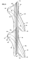
- Fig. 11 is a rear, oblique, schematic perspective view of the tip shroud shown in Fig. 2.
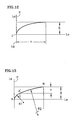
- Fig. 12 and Fig. 13 are simple views respectively of a conical section curve and a two radius curve approximating the conical section curve.
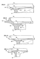
- Fig. 1 is a simplified front elevation view of a rotor assembly 10 of a rotary machine having an axis Ar.
- the rotor assembly includes a rotating structure, as represented by the disk 12, and a plurality of outwardly extending rotor blades 14.
- Each rotor blade has a root 16 and an airfoil 18 being disposed about a spanwisely extending axis S, which is commonly called the stacking line S.
- the airfoil has a pressure side 24 and a suction side 26 as shown in Fig. 3.
- a flowpath 22 for working medium gases extends through the rotor blades between the sides of the airfoil.
- the rotor blade has a tip region 28 having a tip shroud 30.
- the tip shroud includes a seal land 32 which is a surface having a radius of curvature about the axis Ar.
- the tip shroud has a transition zone 34 which extends from the sides 24, 26 of the airfoil, as represented by the pressure side 24 shown in Fig. 1, Fig. 4, and Fig. 5; and, the suction side 26 shown in Fig. 4 and Fig. 6.
- the transition zone includes part of a flowpath surface which extends from a tangent to the pressure side and suction side of the airfoil along a junction J.
- Fig. 2 is a side elevation view of the rotor blade shown in Fig. 1.
- the airfoil 18 has a leading edge 36 and a trailing edge 38.
- the tip shroud has a laterally (circumferentially) extending beam 42 which carries the seal land 32.
- Fig. 3 is a top view of a pair of adjacent tip shrouds 30.
- Each tip shroud has a leading edge region and a trailing edge region.
- the tip shroud includes a depression 48 in the shroud generally radially outwardly of the airfoil and generally following the curve in the tip region of the pressure and suction sides of the airfoil from the leading edge region to the trailing edge region.
- the tip shroud includes a pressure side wing 52 extending from the pressure side of the airfoil having a front portion 52f and a rear portion 52r. The portions of the wing continue the surface of the depression.
- the pressure side wing has a laterally facing pressure side 56.
- the tip shroud includes a suction side wing 54 extending from the suction side of the airfoil having a front portion 54f and a rear portion 54r. The portions of the wing continue the surface of the depression.
- the suction side wing 54 has a laterally facing suction side 58.
- the tip shroud further has the beam 42 which has a front face 42f and a rear face 42r integral with the wings.
- the beam extends laterally between the wings to divide each wing into the front portion and the rear portion and laterally across the depression to divide the depression into a front portion 48f and a rear portion 48r.
- the beam further has a pressure side region 62 extending laterally past the pressure side of the airfoil in the tip region of the airfoil, and has a laterally facing pressure side 63 which adapts the beam to engage the suction side 65 of the beam of the adjacent airfoil.
- the beam also has a similar region on the suction side.
- the suction side region 64 extends laterally past the suction side of the airfoil in the tip region of the airfoil, and has a laterally facing suction side which adapts the suction side of the beam to engage the pressure side of the beam of the adjacent airfoil.
- Fig. 4 is a top view of the rotor blade shown in Fig. 3.
- Fig. 5 and Fig. 6 are side elevation views, respectively, of the pressure side 24 and suction side 26 of the airfoil 18 of the rotor blade shown in Fig. 4.
- the seal land 32 extends radially outwardly from the beam 42.
- the seal land reinforces the beam.
- the combination of the seal land 32 and beam 42 extends to support the front and rear portions of the wings 52, 54 providing a portion of the support required against rotational forces acting on the wings under operative conditions.
- the beam and seal land have an inverted T-shaped cross-sectional shape.
- the axial width Wb of the beam is greater than four times the axial width Ws of the seal land and the radial height Hs of the seal land is greater than twice the height of the beam Hb.
- a fillet radius extends from the front face of the seal land to the front face of the beam and a fillet radius extends from the rear face of the seal land to the rear face of the beam.
- Fig. 5 and Fig. 6 also show the junction J of the transition zone with the pressure side 24 and suction side 26 of the airfoil.
- the junction is formed by an infinite number of junction points each at the point of tangency of the transition zone 34 to the airfoil.
- the tangency of the line provides a smooth transition.
- other types of smooth transitions may exist although a tangent is preferred because of the smooth change that occurs.
- a normal sectioning plane P is shown.
- the normal sectioning plane has a first line La perpendicular to the side of the airfoil at the point of tangency (junction point) and a second line Lb passing through the junction point and parallel to the stacking line S as discussed earlier.
- the offset distances A and B are shown.
- the transition zone extends much further down on the pressure side of the airfoil than on the suction side of the airfoil.
- Fig. 7 is a view from above of one representative airfoil section.
- the surface of the airfoil is defined by a plurality of these airfoil sections each extending perpendicular to the stacking line S.
- Fig. 7 shows the relationship of the leading edge and the trailing edge to a chord line having a length C which connects the leading edge in the trailing edge.
- a mean chord line extends from the leading edge to the trailing edge about midway between the suction side and the pressure side.
- the leading edge region extends about three percent of the length of the chord line along a line tangent to the mean chord line at the leading edge.
- a trailing edge region extending about three percent of the length of the chord line along a line tangent to the mean chord line at the trailing edge,
- Fig. 7 also shows thirteen normal sectioning planes intersecting the transition zone, each having a line of intersection with the surface of the transition zone. The length of the offset distances A is shown. Each sectioning plane shows that the transition zone extends to the side of the wings and under the beam to the extent shown by the curved lines near plane 1 (B1) and plane 8 (B 8).
- the offset ratio is also shown rounded to the nearest hundredths.
- the offset ratio is fairly large and greater than one (A/B>1) on the front portion of the suction side wing and under the beam on the suction side.
- the ratios underneath the beam on the pressure side are smaller but are also greater than one (A/B>1). This is attributable in part to the contouring of the transition zone which has more material extending radially down the side of the airfoil on the pressure side, that is, the offset B, than on the suction side as shown in Fig. 5 and Fig. 6.
- Fig. 8 is a simplified perspective view from the front in cross-section showing a circular transition line on the pressure side of the airfoil.
- the normal sectioning plane P passes through the junction point J.
- the view is not taken parallel to the normal sectioning plane.
- Fig. 9 is a similar view from the front in cross-section of an elliptical transition line on the front wing of the pressure side.
- Fig. 10 is another front view similar to Fig. 9.
- Fig. 11 is a rear view in cross section similar to the front view in Fig. 9 but showing the elliptical transition line extending under the beam.
- the transition zone extends from the junction J on the pressure side 24 of the airfoil to a line B8 under the beam. Accordingly, the transition zone extending under the beam extends to a location between the pressure side 24 of the airfoil and the pressure side 63 of the beam. Similarly, the transition zone ends at a location along the line B1 on the inwardly facing surface of the suction side region of the beam and between the suction side 26 of the airfoil and the suction side 64 of the beam.
- the transition zone over substantially all of its extent between the leading edge region and the trailing edge region extends to the sides of the wings such that each wing has a cross-sectional shape at a location along a normal sectioning plane that is spanwisely tapered to the sides of the wings, and that is spanwisely tapered under the beam at least as far as the immediately adjacent portion of the wing.
- the transition lines in the transition zone that extended only under the wings covered over ninety-nine (99) percent of the surface area (the flow path area) under the wings with the transition zone. In other embodiments, good results are expected where the transition lines extend to cover over ninety-five (95) percent of the wing area with the transition zone.
- the cross-sectional shape of the transition zone has more than one type of curvature to reduce stresses in the rotor blade as compared to transition zones having one type of curvature for the transition zone.
- offset ratios equal to one provide circular transition lines which on the pressure side of the airfoil decreases surface stresses in the airfoil at the rear portion of the pressure side wing.
- Offset ratios greater than one provide elliptical shaped or true elliptical transition lines reduce stress concentration factors better than circular cross-sections. They are heavier constructions than analogous circular transition lines because more material is placed closer to the shroud at greater radial distance from the axis Ar.
- Conical section lines that represent the intersection of a plane with a right circular cone form transition lines that have the advantageous benefits of reducing stress concentration factors. These curves may be used to form transition lines.
- Elliptical transition lines are one example.
- Another example are transition lines formed with curves of multiple radii that follow a conical section lines such as an elliptical transition line and may be formed as shown in Fig. 12. These curves are used on at least one of said sides of the airfoil and show transition lines that extend under the beam that have greater bending away from the airfoil at a region closer to the airfoil on the transition line than at a region closer to the side of the shroud. As a result, and as shown in Fig.
- the average of offset ratios Rb of transition lines that extend under the beam are greater than one and are greater than the average of offset ratios Rw of transition lines that extend only under the rear portion of wings.
- the absolute value of the transition lines Rb is greater than the ratios Rw.
- the transition lines which define the contour of the flow path surface of the shroud for the transition zone of the wing and of the beam follow the shape of part of a conical section. They also have an offset ratio on the suction side of the airfoil for the beam Rb and for the forward portion of the wing Rw that is greater on average than the offset ratio on the pressure side of the airfoil for the beam Rb and for the rear portion of the wing Rw, thus providing a more elliptical flowpath surface on the suction side beam-wing forward region to reduce stress concentration factors in that region.
- Fig. 12 and 13 are examples of a conical transition line and a two radius curve fitted to a conical transition line. As will be realized, more than two curves could be used to generate the same transition line.
Landscapes
- Engineering & Computer Science (AREA)
- Mechanical Engineering (AREA)
- General Engineering & Computer Science (AREA)
- Architecture (AREA)
- Turbine Rotor Nozzle Sealing (AREA)
- Structures Of Non-Positive Displacement Pumps (AREA)
Applications Claiming Priority (4)
| Application Number | Priority Date | Filing Date | Title |
|---|---|---|---|
| US770323 | 1985-08-27 | ||
| US770322 | 2001-01-26 | ||
| US10/770,322 US7134838B2 (en) | 2004-01-31 | 2004-01-31 | Rotor blade for a rotary machine |
| US10/770,323 US7066713B2 (en) | 2004-01-31 | 2004-01-31 | Rotor blade for a rotary machine |
Publications (3)
| Publication Number | Publication Date |
|---|---|
| EP1559870A2 true EP1559870A2 (de) | 2005-08-03 |
| EP1559870A3 EP1559870A3 (de) | 2009-01-07 |
| EP1559870B1 EP1559870B1 (de) | 2011-12-21 |
Family
ID=34657421
Family Applications (1)
| Application Number | Title | Priority Date | Filing Date |
|---|---|---|---|
| EP05250502A Ceased EP1559870B1 (de) | 2004-01-31 | 2005-01-31 | Turbomaschinenlaufschaufel mit Deckband |
Country Status (3)
| Country | Link |
|---|---|
| EP (1) | EP1559870B1 (de) |
| JP (1) | JP2005214205A (de) |
| CN (1) | CN1651723A (de) |
Cited By (2)
| Publication number | Priority date | Publication date | Assignee | Title |
|---|---|---|---|---|
| WO2017018981A1 (en) * | 2015-07-24 | 2017-02-02 | Siemens Aktiengesellschaft | Turbine blade with contoured tip shroud |
| EP3623576A1 (de) * | 2018-09-17 | 2020-03-18 | MTU Aero Engines GmbH | Gasturbinen-laufschaufel |
Families Citing this family (4)
| Publication number | Priority date | Publication date | Assignee | Title |
|---|---|---|---|---|
| US7771171B2 (en) * | 2006-12-14 | 2010-08-10 | General Electric Company | Systems for preventing wear on turbine blade tip shrouds |
| US20110070072A1 (en) * | 2009-09-23 | 2011-03-24 | General Electric Company | Rotary machine tip clearance control mechanism |
| US8721289B2 (en) * | 2009-10-30 | 2014-05-13 | General Electric Company | Flow balancing slot |
| US20130209258A1 (en) * | 2012-02-15 | 2013-08-15 | General Electric Company | Tip shrouded blade |
Citations (4)
| Publication number | Priority date | Publication date | Assignee | Title |
|---|---|---|---|---|
| GB1605335A (en) | 1975-08-23 | 1991-12-18 | Rolls Royce | A rotor blade for a gas turbine engine |
| JPH07233703A (ja) | 1994-02-23 | 1995-09-05 | Mitsubishi Heavy Ind Ltd | ガスタービン動翼のシュラウド |
| US6491498B1 (en) | 2001-10-04 | 2002-12-10 | Power Systems Mfg, Llc. | Turbine blade pocket shroud |
| EP1267042A2 (de) | 2001-06-14 | 2002-12-18 | Mitsubishi Heavy Industries, Ltd. | Gasturbinenschaufel mit Deckband |
Family Cites Families (3)
| Publication number | Priority date | Publication date | Assignee | Title |
|---|---|---|---|---|
| JPS55142908A (en) * | 1979-04-26 | 1980-11-07 | Hitachi Ltd | Turbine moving blade cover |
| DE50304325D1 (de) * | 2002-04-16 | 2006-09-07 | Alstom Technology Ltd | Laufschaufel für eine Turbomaschine |
| US6857853B1 (en) * | 2003-08-13 | 2005-02-22 | General Electric Company | Conical tip shroud fillet for a turbine bucket |
-
2005
- 2005-01-28 JP JP2005020492A patent/JP2005214205A/ja active Pending
- 2005-01-31 EP EP05250502A patent/EP1559870B1/de not_active Ceased
- 2005-01-31 CN CNA2005100061769A patent/CN1651723A/zh active Pending
Patent Citations (4)
| Publication number | Priority date | Publication date | Assignee | Title |
|---|---|---|---|---|
| GB1605335A (en) | 1975-08-23 | 1991-12-18 | Rolls Royce | A rotor blade for a gas turbine engine |
| JPH07233703A (ja) | 1994-02-23 | 1995-09-05 | Mitsubishi Heavy Ind Ltd | ガスタービン動翼のシュラウド |
| EP1267042A2 (de) | 2001-06-14 | 2002-12-18 | Mitsubishi Heavy Industries, Ltd. | Gasturbinenschaufel mit Deckband |
| US6491498B1 (en) | 2001-10-04 | 2002-12-10 | Power Systems Mfg, Llc. | Turbine blade pocket shroud |
Cited By (5)
| Publication number | Priority date | Publication date | Assignee | Title |
|---|---|---|---|---|
| WO2017018981A1 (en) * | 2015-07-24 | 2017-02-02 | Siemens Aktiengesellschaft | Turbine blade with contoured tip shroud |
| CN107849926A (zh) * | 2015-07-24 | 2018-03-27 | 西门子公司 | 具有轮廓尖端罩的涡轮动叶片 |
| EP3623576A1 (de) * | 2018-09-17 | 2020-03-18 | MTU Aero Engines GmbH | Gasturbinen-laufschaufel |
| DE102018215728A1 (de) * | 2018-09-17 | 2020-03-19 | MTU Aero Engines AG | Gasturbinen-Laufschaufel |
| US11377966B2 (en) | 2018-09-17 | 2022-07-05 | MTU Aero Engines AG | Gas turbine moving blade |
Also Published As
| Publication number | Publication date |
|---|---|
| EP1559870A3 (de) | 2009-01-07 |
| EP1559870B1 (de) | 2011-12-21 |
| CN1651723A (zh) | 2005-08-10 |
| JP2005214205A (ja) | 2005-08-11 |
Similar Documents
| Publication | Publication Date | Title |
|---|---|---|
| EP1559871B1 (de) | Laufschaufel für eine Turbomaschine | |
| EP1559869B1 (de) | Laufschaufel für eine Turbomaschine | |
| US8911215B2 (en) | Compressor blade for an axial compressor | |
| US6890150B2 (en) | Center-located cutter teeth on shrouded turbine blades | |
| US8647066B2 (en) | Blade with non-axisymmetric platform: recess and boss on the extrados | |
| JP3896169B2 (ja) | タービンブレード | |
| US5221181A (en) | Stationary turbine blade having diaphragm construction | |
| US7134838B2 (en) | Rotor blade for a rotary machine | |
| US9017030B2 (en) | Turbine component including airfoil with contour | |
| US4460315A (en) | Turbomachine rotor assembly | |
| KR20040095671A (ko) | 터빈 버킷 및 터빈 | |
| US10190423B2 (en) | Shrouded blade for a gas turbine engine | |
| US20150147179A1 (en) | Blade with 3d platform comprising an inter-blade bulb | |
| US5460488A (en) | Shrouded fan blade for a turbine engine | |
| US10704392B2 (en) | Tip shroud fillets for turbine rotor blades | |
| EP1559870B1 (de) | Turbomaschinenlaufschaufel mit Deckband | |
| CN111911240B (zh) | 护罩互锁装置 | |
| US20230383662A1 (en) | Annulus contouring | |
| KR102739238B1 (ko) | 터보 기계용 블레이드, 블레이드 어셈블리, 및 터빈 | |
| CA2091696A1 (en) | Stationary turbine blade having diaphragm construction |
Legal Events
| Date | Code | Title | Description |
|---|---|---|---|
| PUAI | Public reference made under article 153(3) epc to a published international application that has entered the european phase |
Free format text: ORIGINAL CODE: 0009012 |
|
| AK | Designated contracting states |
Kind code of ref document: A2 Designated state(s): AT BE BG CH CY CZ DE DK EE ES FI FR GB GR HU IE IS IT LI LT LU MC NL PL PT RO SE SI SK TR |
|
| AX | Request for extension of the european patent |
Extension state: AL BA HR LV MK YU |
|
| PUAL | Search report despatched |
Free format text: ORIGINAL CODE: 0009013 |
|
| AK | Designated contracting states |
Kind code of ref document: A3 Designated state(s): AT BE BG CH CY CZ DE DK EE ES FI FR GB GR HU IE IS IT LI LT LU MC NL PL PT RO SE SI SK TR |
|
| AX | Request for extension of the european patent |
Extension state: AL BA HR LV MK YU |
|
| 17P | Request for examination filed |
Effective date: 20090406 |
|
| AKX | Designation fees paid |
Designated state(s): DE GB |
|
| 17Q | First examination report despatched |
Effective date: 20091127 |
|
| RTI1 | Title (correction) |
Free format text: SHROUDED ROTOR BLADE FOR A TURBOMACHINE |
|
| GRAP | Despatch of communication of intention to grant a patent |
Free format text: ORIGINAL CODE: EPIDOSNIGR1 |
|
| GRAS | Grant fee paid |
Free format text: ORIGINAL CODE: EPIDOSNIGR3 |
|
| GRAA | (expected) grant |
Free format text: ORIGINAL CODE: 0009210 |
|
| AK | Designated contracting states |
Kind code of ref document: B1 Designated state(s): DE GB |
|
| REG | Reference to a national code |
Ref country code: GB Ref legal event code: FG4D |
|
| REG | Reference to a national code |
Ref country code: DE Ref legal event code: R081 Ref document number: 602005031734 Country of ref document: DE Owner name: UNITED TECHNOLOGIES CORP. (N.D.GES.D. STAATES , US Free format text: FORMER OWNER: UNITED TECHNOLOGIES CORP. (N.D.GES.D. STAATES DELAWARE), HARTFORD, CONN., US |
|
| REG | Reference to a national code |
Ref country code: DE Ref legal event code: R096 Ref document number: 602005031734 Country of ref document: DE Effective date: 20120216 |
|
| PLBE | No opposition filed within time limit |
Free format text: ORIGINAL CODE: 0009261 |
|
| STAA | Information on the status of an ep patent application or granted ep patent |
Free format text: STATUS: NO OPPOSITION FILED WITHIN TIME LIMIT |
|
| 26N | No opposition filed |
Effective date: 20120924 |
|
| REG | Reference to a national code |
Ref country code: DE Ref legal event code: R097 Ref document number: 602005031734 Country of ref document: DE Effective date: 20120924 |
|
| REG | Reference to a national code |
Ref country code: DE Ref legal event code: R082 Ref document number: 602005031734 Country of ref document: DE Representative=s name: SCHMITT-NILSON SCHRAUD WAIBEL WOHLFROM PATENTA, DE |
|
| REG | Reference to a national code |
Ref country code: DE Ref legal event code: R082 Ref document number: 602005031734 Country of ref document: DE Representative=s name: SCHMITT-NILSON SCHRAUD WAIBEL WOHLFROM PATENTA, DE Ref country code: DE Ref legal event code: R081 Ref document number: 602005031734 Country of ref document: DE Owner name: UNITED TECHNOLOGIES CORP. (N.D.GES.D. STAATES , US Free format text: FORMER OWNER: UNITED TECHNOLOGIES CORPORATION, HARTFORD, CONN., US |
|
| PGFP | Annual fee paid to national office [announced via postgrant information from national office to epo] |
Ref country code: GB Payment date: 20191223 Year of fee payment: 16 Ref country code: DE Payment date: 20191218 Year of fee payment: 16 |
|
| REG | Reference to a national code |
Ref country code: DE Ref legal event code: R119 Ref document number: 602005031734 Country of ref document: DE |
|
| GBPC | Gb: european patent ceased through non-payment of renewal fee |
Effective date: 20210131 |
|
| PG25 | Lapsed in a contracting state [announced via postgrant information from national office to epo] |
Ref country code: DE Free format text: LAPSE BECAUSE OF NON-PAYMENT OF DUE FEES Effective date: 20210803 Ref country code: GB Free format text: LAPSE BECAUSE OF NON-PAYMENT OF DUE FEES Effective date: 20210131 |