EP1559849A2 - Profile of plastic material for fixing elements in walls or the like - Google Patents
Profile of plastic material for fixing elements in walls or the like Download PDFInfo
- Publication number
- EP1559849A2 EP1559849A2 EP04105817A EP04105817A EP1559849A2 EP 1559849 A2 EP1559849 A2 EP 1559849A2 EP 04105817 A EP04105817 A EP 04105817A EP 04105817 A EP04105817 A EP 04105817A EP 1559849 A2 EP1559849 A2 EP 1559849A2
- Authority
- EP
- European Patent Office
- Prior art keywords
- profile
- notches
- orifices
- walls
- plastic material
- Prior art date
- Legal status (The legal status is an assumption and is not a legal conclusion. Google has not performed a legal analysis and makes no representation as to the accuracy of the status listed.)
- Withdrawn
Links
Images

Classifications
-
- A—HUMAN NECESSITIES
- A47—FURNITURE; DOMESTIC ARTICLES OR APPLIANCES; COFFEE MILLS; SPICE MILLS; SUCTION CLEANERS IN GENERAL
- A47B—TABLES; DESKS; OFFICE FURNITURE; CABINETS; DRAWERS; GENERAL DETAILS OF FURNITURE
- A47B96/00—Details of cabinets, racks or shelf units not covered by a single one of groups A47B43/00 - A47B95/00; General details of furniture
- A47B96/14—Bars, uprights, struts, or like supports, for cabinets, brackets, or the like
- A47B96/1466—Bars, uprights, struts, or like supports, for cabinets, brackets, or the like with longitudinal grooves
- A47B96/1475—Bars, uprights, struts, or like supports, for cabinets, brackets, or the like with longitudinal grooves and perforations
-
- E—FIXED CONSTRUCTIONS
- E04—BUILDING
- E04F—FINISHING WORK ON BUILDINGS, e.g. STAIRS, FLOORS
- E04F13/00—Coverings or linings, e.g. for walls or ceilings
- E04F13/07—Coverings or linings, e.g. for walls or ceilings composed of covering or lining elements; Sub-structures therefor; Fastening means therefor
- E04F13/08—Coverings or linings, e.g. for walls or ceilings composed of covering or lining elements; Sub-structures therefor; Fastening means therefor composed of a plurality of similar covering or lining elements
- E04F13/0801—Separate fastening elements
- E04F13/0803—Separate fastening elements with load-supporting elongated furring elements between wall and covering elements
-
- E—FIXED CONSTRUCTIONS
- E04—BUILDING
- E04F—FINISHING WORK ON BUILDINGS, e.g. STAIRS, FLOORS
- E04F19/00—Other details of constructional parts for finishing work on buildings
- E04F19/02—Borders; Finishing strips, e.g. beadings; Light coves
- E04F19/06—Borders; Finishing strips, e.g. beadings; Light coves specially designed for securing panels or masking the edges of wall- or floor-covering elements
Definitions
- the present invention relates to a profile of plastic material for fixing elements in walls and the like.
- This kind of profiles usually has a 'C'-shaped cross section. This shape allows screwing or nailing the profile to the wall by its bottom, and using the lateral flanges to fix a sliding screw or a bridle at any point along the profile.
- Profiles of this kind which can be manually cut have been designed, in such a way that the user can choose the length of each portion of profile that he needs without needing to use cutting devices.
- profiles are made from a metallic sheet which is punched, forming a plurality of orifices which will be used to fix the profile to the wall. Punching the sheet every certain distance forms an orifice wider than the others, which will be used as a fracture point when the profile is manually cut.
- the sheet is folded by its lateral ends and the profile is formed, the orifices being placed in the bottom of it. Therefore, when the profile has to be cut, it is broken by the points corresponding to the wider orifices, which span almost all the width of the bottom of the profile.
- the aim of the present invention is to solve the disadvantages that have the devices known in the art, providing a profile of plastic material for fixing elements in walls or the like, which comprises a substantially 'C'-shaped cross section defined by a bottom and a pair of lateral flanges, which is characterized in that the profile comprises, in the lateral flanges, a plurality of notches for breaking it.
- the bottom of the profile comprises a plurality of orifices for fixing the profile to a wall or the like.
- the profile is easily fixed by its bottom to the wall using screws or nails.
- the orifices closer to the notches are wider.
- the fracture cross section is smaller, and, therefore, the effort that the user has to carry out to break the profile is also decreased.
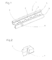
- the profile 1 has a 'C'-shaped section, with a bottom 2 and a pair of lateral 'L'-shaped parallel flanges 3.
- Each flange 3 has fracture notches 4 every certain distance. These notches 4 are situated each in front of the other in each flange 3 to make the fracture of the profile 1 possible.
- the bottom 2 of the profile 1 has a plurality of orifices 5 for fixing it by screwing or nailing it to a wall or the like.
- the notches 4 decrease the cross section of the profile 1 in the fracture zone. Moreover, the orifices 6 situated closer to the notches are wider than the other. This facilitates breaking the profile 1 in said zone.
- the profile 1 can be manually broken by bending it, without needing to use cutting devices.
- a suitable distance between the notches will be provided according to the use requirements of each profile 1.
Abstract
Description
- The present invention relates to a profile of plastic material for fixing elements in walls and the like.
- Profiles used for holding all kind of elements to walls or other supports which allow fixing screws or bridles along it in a quick and effective way, are known.
- This kind of profiles usually has a 'C'-shaped cross section. This shape allows screwing or nailing the profile to the wall by its bottom, and using the lateral flanges to fix a sliding screw or a bridle at any point along the profile.
- Profiles of this kind which can be manually cut have been designed, in such a way that the user can choose the length of each portion of profile that he needs without needing to use cutting devices.
- These profiles are made from a metallic sheet which is punched, forming a plurality of orifices which will be used to fix the profile to the wall. Punching the sheet every certain distance forms an orifice wider than the others, which will be used as a fracture point when the profile is manually cut.
- Once it has been punched, the sheet is folded by its lateral ends and the profile is formed, the orifices being placed in the bottom of it. Therefore, when the profile has to be cut, it is broken by the points corresponding to the wider orifices, which span almost all the width of the bottom of the profile.
- Similar profiles made of plastic are known. However, the profiles made of plastic can't be made using the described procedure, as they are made by extrusion, and the profile has to be punched to form the orifices after it has been formed. This does not allow making orifices in the bottom of the profile wide enough to break it, so it can't be cut manually.
- The aim of the present invention is to solve the disadvantages that have the devices known in the art, providing a profile of plastic material for fixing elements in walls or the like, which comprises a substantially 'C'-shaped cross section defined by a bottom and a pair of lateral flanges, which is characterized in that the profile comprises, in the lateral flanges, a plurality of notches for breaking it.
- Therefore, a profile which can be manually cut without using any device is provided. The notches in both lateral flanges are fracture points, so that the user only has to bend it with his hands to obtain profile portions of a given length.
- The fact that the notches are in the flanges of the profile avoids the disadvantage of the impossibility of making 'C'-shaped plastic profiles with fracture orifices in its bottom.
- Preferably, the bottom of the profile comprises a plurality of orifices for fixing the profile to a wall or the like.
- Therefore, the profile is easily fixed by its bottom to the wall using screws or nails.
- Advantageously, the orifices closer to the notches are wider.
- Thanks to these wider orifices, the fracture cross section is smaller, and, therefore, the effort that the user has to carry out to break the profile is also decreased.
- In order to assist the description of all that has been outlined above some drawings are attached which show schematically and solely by way of non-restrictive example a practical case of embodiment of the device profile of the invention, in which:
- Figure 1 is a perspective view of the profile of the invention;
- Figure 2 is a detail view of one of the notches of the profile;
- Figure 3 is a plan view of a section of the profile of the invention;
- Figure 4 is a cross section view of the profile of the invention.
-
- As shown in the figures, the profile 1 has a 'C'-shaped section, with a
bottom 2 and a pair of lateral 'L'-shapedparallel flanges 3. - Each
flange 3 hasfracture notches 4 every certain distance. Thesenotches 4 are situated each in front of the other in eachflange 3 to make the fracture of the profile 1 possible. - The
bottom 2 of the profile 1 has a plurality oforifices 5 for fixing it by screwing or nailing it to a wall or the like. - As it can be seen, the
notches 4 decrease the cross section of the profile 1 in the fracture zone. Moreover, theorifices 6 situated closer to the notches are wider than the other. This facilitates breaking the profile 1 in said zone. - Thus, the profile 1 can be manually broken by bending it, without needing to use cutting devices.
- A suitable distance between the notches will be provided according to the use requirements of each profile 1.
- Although in the described preferred embodiment triangular
cross section notches 4 have been represented, it is obvious thatnotches 4 of different shape could also be provided.
Claims (3)
- Profile (1) of plastic material for fixing elements in walls or the like, which comprises a substantially 'C'-shaped cross section defined by a bottom (2) and a pair of lateral flanges (3), characterized in that the profile (1) comprises, in the lateral flanges (3), a plurality of notches (4) for breaking it.
- Profile (1), according to claim 1, characterized in that the bottom (2) comprises a plurality of orifices (5) for fixing the profile (1) to a wall or the like.
- Profile (1), according to claim 2, characterized in that the orifices (6) closer to the notches (4) are wider.
Applications Claiming Priority (2)
| Application Number | Priority Date | Filing Date | Title |
|---|---|---|---|
| ES200400179U ES1056645Y (en) | 2004-01-29 | 2004-01-29 | PROFILE OF PLASTIC MATERIAL FOR THE FIXATION OF ELEMENTS IN WALLS OR SIMILAR |
| ES200400179U | 2004-01-29 |
Publications (2)
| Publication Number | Publication Date |
|---|---|
| EP1559849A2 true EP1559849A2 (en) | 2005-08-03 |
| EP1559849A3 EP1559849A3 (en) | 2008-05-14 |
Family
ID=32187509
Family Applications (1)
| Application Number | Title | Priority Date | Filing Date |
|---|---|---|---|
| EP04105817A Withdrawn EP1559849A3 (en) | 2004-01-29 | 2004-11-16 | Profile of plastic material for fixing elements in walls or the like |
Country Status (2)
| Country | Link |
|---|---|
| EP (1) | EP1559849A3 (en) |
| ES (1) | ES1056645Y (en) |
Cited By (1)
| Publication number | Priority date | Publication date | Assignee | Title |
|---|---|---|---|---|
| EP1801313A1 (en) * | 2005-12-23 | 2007-06-27 | Richard Anthony Whiting | Engaging assembly for a floor covering, in particular floor trim assembly |
Citations (4)
| Publication number | Priority date | Publication date | Assignee | Title |
|---|---|---|---|---|
| AT399641B (en) * | 1990-06-27 | 1995-06-26 | Mesner Walter | Multipurpose profile system |
| EP0844342A2 (en) * | 1996-11-13 | 1998-05-27 | Gerd Stuckenbrok | Profile for walls or ceilings to be used for all dry constructions |
| WO1998032931A1 (en) * | 1997-01-29 | 1998-07-30 | Massimo Ferrante | Method of fabricating rigid section bars able to be articulated manually, usable as a frame for walls, false walls, false ceilings and the like and section bars obtained thereby |
| DE20206281U1 (en) * | 2002-04-20 | 2002-08-01 | Richter System Gmbh & Co Kg | Support profile for several C profile rails |
-
2004
- 2004-01-29 ES ES200400179U patent/ES1056645Y/en not_active Expired - Fee Related
- 2004-11-16 EP EP04105817A patent/EP1559849A3/en not_active Withdrawn
Patent Citations (4)
| Publication number | Priority date | Publication date | Assignee | Title |
|---|---|---|---|---|
| AT399641B (en) * | 1990-06-27 | 1995-06-26 | Mesner Walter | Multipurpose profile system |
| EP0844342A2 (en) * | 1996-11-13 | 1998-05-27 | Gerd Stuckenbrok | Profile for walls or ceilings to be used for all dry constructions |
| WO1998032931A1 (en) * | 1997-01-29 | 1998-07-30 | Massimo Ferrante | Method of fabricating rigid section bars able to be articulated manually, usable as a frame for walls, false walls, false ceilings and the like and section bars obtained thereby |
| DE20206281U1 (en) * | 2002-04-20 | 2002-08-01 | Richter System Gmbh & Co Kg | Support profile for several C profile rails |
Cited By (1)
| Publication number | Priority date | Publication date | Assignee | Title |
|---|---|---|---|---|
| EP1801313A1 (en) * | 2005-12-23 | 2007-06-27 | Richard Anthony Whiting | Engaging assembly for a floor covering, in particular floor trim assembly |
Also Published As
| Publication number | Publication date |
|---|---|
| ES1056645Y (en) | 2004-08-01 |
| ES1056645U (en) | 2004-04-16 |
| EP1559849A3 (en) | 2008-05-14 |
Similar Documents
| Publication | Publication Date | Title |
|---|---|---|
| US20060230687A1 (en) | Solid edge gutter screen | |
| CA2623416C (en) | Beam for a drywall ceiling soffit | |
| US20160023873A1 (en) | Pry bar | |
| US9091078B2 (en) | Attachment device for sheet type construction siding | |
| ATE494784T1 (en) | TOAST SLICE, TOAST BREAD, METHOD FOR THE PRODUCTION THEREOF AND BREAD BOX SUITABLE THEREFOR | |
| EP3082508A1 (en) | Drawer wall element | |
| EP1788681B9 (en) | Engageable stretch of cable trays | |
| EP1559849A2 (en) | Profile of plastic material for fixing elements in walls or the like | |
| HUP0103351A2 (en) | Metal channel for securing studs for wall panels | |
| ES2586809T3 (en) | Deformable guide for partitions in general | |
| US20080131233A1 (en) | Plate-shaped fastener device | |
| WO2009059731A8 (en) | Metal profile | |
| WO2009009626A1 (en) | Tracks, methods for use thereof, and apparatus, system, and method for manufacture | |
| FI20165594A (en) | PRODUCT DISPENSING PACKAGING AND METHOD FOR MAKING IT | |
| EP2706163A2 (en) | Inverted T profile for forming false ceiling support structures | |
| US20160002928A1 (en) | Masonry Reinforcement, Dispenser For Stripe-Type Masonry Reinforcement, Method to Reinforce a Masonry and Method to Produce a Reinforcement Stripe | |
| ITNA990068A1 (en) | PARTIALLY RIGID PROFILE HAVING APPROXIMATE CROSS-SHEARS AND A CONTINUOUS LONGITUDINAL RIB, SITUATED BETWEEN | |
| EP1445392A3 (en) | Building frame member | |
| ATE476369T1 (en) | IMPROVED BOX HANDLE | |
| WO2006128927A3 (en) | Disposable and/or reusable folding cage comprising a removable excrement collection box | |
| DE202006002616U1 (en) | Device for producing hanging ceilings comprises a U-shaped bent sheet metal profile with the hanging ceiling plates fixed directly to U-shaped sides or via a C-rail | |
| JP2004011317A (en) | Grating | |
| US20050102965A1 (en) | Device and method for correcting misalignment of building structural parts | |
| BE1022072B1 (en) | HANDRAIL HOLDER AND METHOD FOR INSTALLING A HANDRAIL | |
| BE1023594B1 (en) | METAL ROOF AND / OR FACADE COVERING AND METHOD FOR COVERING A ROOF AND / OR FACADE |
Legal Events
| Date | Code | Title | Description |
|---|---|---|---|
| PUAI | Public reference made under article 153(3) epc to a published international application that has entered the european phase |
Free format text: ORIGINAL CODE: 0009012 |
|
| AK | Designated contracting states |
Kind code of ref document: A2 Designated state(s): AT BE BG CH CY CZ DE DK EE ES FI FR GB GR HU IE IS IT LI LU MC NL PL PT RO SE SI SK TR |
|
| AX | Request for extension of the european patent |
Extension state: AL HR LT LV MK YU |
|
| PUAL | Search report despatched |
Free format text: ORIGINAL CODE: 0009013 |
|
| AK | Designated contracting states |
Kind code of ref document: A3 Designated state(s): AT BE BG CH CY CZ DE DK EE ES FI FR GB GR HU IE IS IT LI LU MC NL PL PT RO SE SI SK TR |
|
| AX | Request for extension of the european patent |
Extension state: AL HR LT LV MK YU |
|
| AKX | Designation fees paid | ||
| REG | Reference to a national code |
Ref country code: DE Ref legal event code: 8566 |
|
| STAA | Information on the status of an ep patent application or granted ep patent |
Free format text: STATUS: THE APPLICATION IS DEEMED TO BE WITHDRAWN |
|
| 18D | Application deemed to be withdrawn |
Effective date: 20081115 |