EP1559796A1 - Method of increasing toughness of heat-affected part of steel product welded joint - Google Patents
Method of increasing toughness of heat-affected part of steel product welded joint Download PDFInfo
- Publication number
- EP1559796A1 EP1559796A1 EP03769982A EP03769982A EP1559796A1 EP 1559796 A1 EP1559796 A1 EP 1559796A1 EP 03769982 A EP03769982 A EP 03769982A EP 03769982 A EP03769982 A EP 03769982A EP 1559796 A1 EP1559796 A1 EP 1559796A1
- Authority
- EP
- European Patent Office
- Prior art keywords
- steel plate
- welded joint
- affected zone
- toughness
- heat affected
- Prior art date
- Legal status (The legal status is an assumption and is not a legal conclusion. Google has not performed a legal analysis and makes no representation as to the accuracy of the status listed.)
- Granted
Links
Images


Classifications
-
- C—CHEMISTRY; METALLURGY
- C21—METALLURGY OF IRON
- C21D—MODIFYING THE PHYSICAL STRUCTURE OF FERROUS METALS; GENERAL DEVICES FOR HEAT TREATMENT OF FERROUS OR NON-FERROUS METALS OR ALLOYS; MAKING METAL MALLEABLE, e.g. BY DECARBURISATION OR TEMPERING
- C21D7/00—Modifying the physical properties of iron or steel by deformation
- C21D7/02—Modifying the physical properties of iron or steel by deformation by cold working
- C21D7/04—Modifying the physical properties of iron or steel by deformation by cold working of the surface
- C21D7/06—Modifying the physical properties of iron or steel by deformation by cold working of the surface by shot-peening or the like
-
- B—PERFORMING OPERATIONS; TRANSPORTING
- B23—MACHINE TOOLS; METAL-WORKING NOT OTHERWISE PROVIDED FOR
- B23K—SOLDERING OR UNSOLDERING; WELDING; CLADDING OR PLATING BY SOLDERING OR WELDING; CUTTING BY APPLYING HEAT LOCALLY, e.g. FLAME CUTTING; WORKING BY LASER BEAM
- B23K20/00—Non-electric welding by applying impact or other pressure, with or without the application of heat, e.g. cladding or plating
- B23K20/10—Non-electric welding by applying impact or other pressure, with or without the application of heat, e.g. cladding or plating making use of vibrations, e.g. ultrasonic welding
-
- B—PERFORMING OPERATIONS; TRANSPORTING
- B23—MACHINE TOOLS; METAL-WORKING NOT OTHERWISE PROVIDED FOR
- B23K—SOLDERING OR UNSOLDERING; WELDING; CLADDING OR PLATING BY SOLDERING OR WELDING; CUTTING BY APPLYING HEAT LOCALLY, e.g. FLAME CUTTING; WORKING BY LASER BEAM
- B23K33/00—Specially-profiled edge portions of workpieces for making soldering or welding connections; Filling the seams formed thereby
- B23K33/004—Filling of continuous seams
-
- C—CHEMISTRY; METALLURGY
- C21—METALLURGY OF IRON
- C21D—MODIFYING THE PHYSICAL STRUCTURE OF FERROUS METALS; GENERAL DEVICES FOR HEAT TREATMENT OF FERROUS OR NON-FERROUS METALS OR ALLOYS; MAKING METAL MALLEABLE, e.g. BY DECARBURISATION OR TEMPERING
- C21D10/00—Modifying the physical properties by methods other than heat treatment or deformation
-
- C—CHEMISTRY; METALLURGY
- C21—METALLURGY OF IRON
- C21D—MODIFYING THE PHYSICAL STRUCTURE OF FERROUS METALS; GENERAL DEVICES FOR HEAT TREATMENT OF FERROUS OR NON-FERROUS METALS OR ALLOYS; MAKING METAL MALLEABLE, e.g. BY DECARBURISATION OR TEMPERING
- C21D7/00—Modifying the physical properties of iron or steel by deformation
- C21D7/02—Modifying the physical properties of iron or steel by deformation by cold working
- C21D7/04—Modifying the physical properties of iron or steel by deformation by cold working of the surface
-
- B—PERFORMING OPERATIONS; TRANSPORTING
- B23—MACHINE TOOLS; METAL-WORKING NOT OTHERWISE PROVIDED FOR
- B23K—SOLDERING OR UNSOLDERING; WELDING; CLADDING OR PLATING BY SOLDERING OR WELDING; CUTTING BY APPLYING HEAT LOCALLY, e.g. FLAME CUTTING; WORKING BY LASER BEAM
- B23K2103/00—Materials to be soldered, welded or cut
- B23K2103/02—Iron or ferrous alloys
- B23K2103/04—Steel or steel alloys
-
- C—CHEMISTRY; METALLURGY
- C21—METALLURGY OF IRON
- C21D—MODIFYING THE PHYSICAL STRUCTURE OF FERROUS METALS; GENERAL DEVICES FOR HEAT TREATMENT OF FERROUS OR NON-FERROUS METALS OR ALLOYS; MAKING METAL MALLEABLE, e.g. BY DECARBURISATION OR TEMPERING
- C21D9/00—Heat treatment, e.g. annealing, hardening, quenching or tempering, adapted for particular articles; Furnaces therefor
- C21D9/50—Heat treatment, e.g. annealing, hardening, quenching or tempering, adapted for particular articles; Furnaces therefor for welded joints
-
- Y—GENERAL TAGGING OF NEW TECHNOLOGICAL DEVELOPMENTS; GENERAL TAGGING OF CROSS-SECTIONAL TECHNOLOGIES SPANNING OVER SEVERAL SECTIONS OF THE IPC; TECHNICAL SUBJECTS COVERED BY FORMER USPC CROSS-REFERENCE ART COLLECTIONS [XRACs] AND DIGESTS
- Y10—TECHNICAL SUBJECTS COVERED BY FORMER USPC
- Y10T—TECHNICAL SUBJECTS COVERED BY FORMER US CLASSIFICATION
- Y10T29/00—Metal working
- Y10T29/45—Scale remover or preventor
- Y10T29/4572—Mechanically powered operator
- Y10T29/4578—Tack or needle type
-
- Y—GENERAL TAGGING OF NEW TECHNOLOGICAL DEVELOPMENTS; GENERAL TAGGING OF CROSS-SECTIONAL TECHNOLOGIES SPANNING OVER SEVERAL SECTIONS OF THE IPC; TECHNICAL SUBJECTS COVERED BY FORMER USPC CROSS-REFERENCE ART COLLECTIONS [XRACs] AND DIGESTS
- Y10—TECHNICAL SUBJECTS COVERED BY FORMER USPC
- Y10T—TECHNICAL SUBJECTS COVERED BY FORMER US CLASSIFICATION
- Y10T29/00—Metal working
- Y10T29/45—Scale remover or preventor
- Y10T29/4572—Mechanically powered operator
- Y10T29/4583—Hammer
Definitions
- the present invention relates to a method of improvement of toughness of a heat affected zone in a welded joint of a steel plate used for buildings, shipbuildings, bridges, construction machines, offshore structures, and other welded structures. Specifically, the present invention relates to a method of improvement of toughness of a heat affected zone in a multi-layer welded joint, a fillet welded joint, and a one-pass or several-pass large heat input welded joint.
- the microstructure of the steel plate coarsens due to the heat input at welding.
- the subsequent welding pass the region where the coarsened crystal grains is heated again, so the crystal grains become finer. Therefore, a high toughness is secured also in the heat affected zone (HAZ, same below).
- HAZ heat affected zone
- the HAZ formed by a last pass near the surface of the steel plate is not subjected to a subsequent welding pass, therefore the crystal grains are not made finer by re-heating. The crystal grains remain coarse as they are, so the fracture toughness is greatly degraded.
- Kinzoku Binran Metal Handbook
- Maruzen Ltd. p. 1072, FIGS. 16 to 50
- the microstructure of a welding heat affected zone that the microstructure once completely becomes austenite by heating, which thus becomes extremely coarse, apt to harden and crack.
- a steel plate to which a one-pass or several-pass welded joint obtained by large heat input welding is applied is generally designed to prevent the coarsening of the HAZ microstructure even without repeated heat input by a subsequent welding pass by increasing the refinement and dispersing TiN, oxides, etc. in the steel plate matrix and thereby enabling suppression of the austenite grain growth by the pinning effect of TiN, oxides, etc.
- the HAZ microstructure easily become coarse when the amount of heat input of the welding is large. Therefore, if restricting the amount of heat input or improving the welding efficiency by making the groove narrower and nearer to vertical, the steel plate matrix is not sufficiently melted and the weld metal ends up solidifying earlier. Therefore, undercut in welding easily occurs at the toe portion. This zone becomes a stress concentration site and becomes a fracture initiation point, so there arises a problem of a remarkable drop in the fracture toughness.
- U.S. Patent No. 6,171,415 discloses a method of imparting ultrasonic vibration along a welding seam heated by a welding arc immediately after arc welding.
- this prior art is a method of improving the fatigue strength by impacts by an ultrasonic vibrator and does not discloses anything about increasing the refinement of the microstructure of the HAZ or improving the toughness by pressing together the poorly fused parts of the object of the present invention.
- the present invention solves the problems of the prior art as explained above and provides a method of improvement of toughness of a heat affected zone in a multi-layer welded joint, a fillet welded joint, or a one-pass or several-pass large heat input welded joint of a steel plate.
- the present invention was made as results of intensive study in order to solve the previously explained problems and provides a method of improvement of toughness of a heat affected zone in a multi-layer welded joint, a fillet welded joint, or a one-pass or several-pass large heat input welded joint of a steel plate by impacts by an ultrasonic vibration tool or shot peening by ultrasonic vibration steel balls at the vicinity of the welded joint of the steel plate.
- a gist of the present invention is as follows.
- FIG. 1 to FIG. 6 A detailed explanation will be given of embodiments of the present invention by using FIG. 1 to FIG. 6.
- FIG. 1 is a view of a first embodiment of a method of improvement of toughness of a heat affected zone in a multi-layer welded joint of a steel plate of the present invention.
- a steel plate 1 and a steel plate 2 are joined by a multi-layer welded joint
- 3 indicates a weld metal
- 4 indicates a last welding pass
- 5 indicates a heat affected zone (HAZ) formed by the last welding pass
- 6 indicates an ultrasonic vibration tool
- 7 indicates a fusion line (FL) of a steel plate matrix and a weld metal
- t indicates a thickness of the steel plate matrix.
- the crystal grains become finer by a heat cycle and a high toughness is maintained.
- the HAZ 5 heated by the last welding pass 4 of FIG. 1 does not have a subsequent pass, so the crystal grains remain coarse as they are.
- an ultrasonic vibration tool (hammer) 6 is used for ultrasonic impact treatment for impacts the surface of the HAZ 5 to make the microstructure of the HAZ finer and as a result remarkably improve the toughness.
- the mechanism is not clear, but it is assumed that the high frequency impacts by the ultrasonic vibration tool 6 causes the surface of the steel plate to plastically deform and the heat of working generated causes the microstructure of the HAZ to recrystallize and become finer.
- the steel plate is supplementally heated before or during the impacts by the ultrasonic vibration tool or the shot peening by the ultrasonic wave vibration steel balls.
- the supplementally heating method is not a limited, but the induction heating method or electrical heating method not requiring large scale facilities is preferred.
- the ultrasonic wave generation apparatus used in the present invention is not limited, but an apparatus generating an ultrasonic oscillation of 19 kHz to 60 kHz by a transducer by using a power supply of 200W to 3 kW, amplifying it by a waveguide, and thereby vibrating an ultrasonic vibration tool using one or more pins having a diameter of between ⁇ 5 mm up to ⁇ 30 mm with an oscillating amplitude of between 20 to 60 ⁇ m. Further, in place of the ultrasonic vibration tool 6, it is also possible to perform ultrasonic shot peening making steel balls having a diameter of 1 to 3 mm given vibration by ultrasonic waves strike the surface of the steel plate.
- the surface of the HAZ on the steel plate 2 side is subjected to the ultrasonic impacts or the ultrasonic shot peening, but the surface of the HAZ on the steel plate 1 side may also be subjected to the ultrasonic impacts or the ultrasonic shot peening.
- FIG. 2 is a detailed view of the HAZ 5 in FIG. 1.
- 3 indicates a weld metal
- 7 indicates a fusion line (FL) of the weld metal and the steel plate matrix
- 8 indicates crystal grains adjacent to the fusion line (FL)
- 10 indicates the toe portion.
- the average of the longitudinal axis of the crystal gains up to a depth t0 of 2 mm or more from the surface of the steel plate is made equivalent to the crystal grain size of the steel plate matrix before the welding at the depth of 1/4 of the thickness t from the surface of the steel plate.
- microstructure of the steel plate matrix here, according to the steel plate to be used, a microstructure of a combination of one or more of a ferrite structure, ferrite-pearlite structure, bainite structure, martensite structure, etc. is permitted.
- t0 is made up to the depth of 2 mm or more because the effect of improvement of toughness is insufficient if the depth is less than 2 mm.
- the average of the longitudinal axis of the crystal grains is made equivalent to the crystal grain size of the steel plate matrix before welding at the depth of 1/4 of the thickness t from the steel plate surface because it is sufficient so far as a toughness equivalent to the toughness in a representative place of the steel plate matrix before the welding can be secured.
- the average of the longitudinal axis of the crystal grains is made 30 ⁇ m or less in order to sufficiently exhibit this effect of improvement of the toughness. Note that, as the unit measure of fracture, the long axis of the crystal grains having a higher correlation with the fracture toughness was employed.
- the crystal grains adjacent to the fusion line of the HAZ may be comprised of, according to the steel plate to be used, not only microstructures of the same types as the steel plate matrix, but also these microstructures wherein all or part surrounded by a grain boundary ferrite or ferrite side plates.
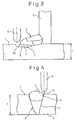
- FIG. 3 is a view of a second embodiment of a method of improvement of toughness of a heat affected zone in a fillet welded joint of a steel plate of the present invention.
- a corner formed by perpendicularly combining a steel plate 1 and a steel plate 2 is joined by fillet welding
- 3 indicates a weld metal
- 4 indicates a welding pass adjacent to the toe portion
- 5 indicates a heat affected zone (HAZ) formed by a pass adjacent to the toe portion
- 6 indicates an ultrasonic vibration tool
- 7 indicates a fusion line (FL) of a steel plate matrix and a weld metal
- t indicates a thickness of the steel plate matrix
- 10 indicates a toe portion.
- the ultrasonic impacts for impacts the vicinity of the toe most requiring the fracture toughness by the ultrasonic vibration tool (hammer) 6 the microstructure of the HAZ portion is made finer and as a result the toughness can be remarkably improved.
- the mechanism is not clear, but is considered to be the high frequency impacts by the ultrasonic vibration tool 6 causes the surface of the steel plate to plastically deform and the heat of working generated causes the microstructure of the HAZ to recrystallize and become finer.
- the steel plate is supplementally heated before or during impacts by the ultrasonic vibration tool or the shot peening by the ultrasonic wave vibration steel balls.
- the supplemental heating method is not limited, but the induction heating method or electrical heating method not requiring large scale facilities is preferred.
- the ultrasonic wave generation apparatus used in the present invention is not limited, but an apparatus generating an ultrasonic vibration of 19 kHz to 60 kHz by a transducer by using a power supply of 200W to 3 kW, amplifying it by a waveguide, and thereby vibrating an ultrasonic vibration tool using one or more pins having a diameter of between ⁇ 5 mm up to ⁇ 30 mm with an oscillating amplitude of between 20 to 60 ⁇ m. Further, in place of the ultrasonic vibration tool 6, it is also possible to perform ultrasonic shot peening making steel balls having a diameter of 1 to 3 mm given vibration by ultrasonic waves strike the surface of the steel plate.
- the conditions and reason for increasing the fineness of the HAZ for making the average of the longitudinal axis of crystal grains up to the depth of 2 mm or more from the surface of the steel plate equivalent to the crystal grain size of the steel plate matrix before welding at the depth of 1/4 of the thickness t from the steel plate surface are the same as those of the case of the multi-layer welded joint.
- FIG. 4 is a view of a third embodiment of a method of improvement of toughness of a heat affected zone in a one-pass or several-pass large heat input welded joint of a steel plate of the present invention.
- the steel plate 1 and the steel plate 2 are joined to form a large heat input welded joint
- 3 indicates a weld metal
- 4 indicates the last welding pass
- 6 indicates an ultrasonic vibration tool
- 7 indicates a fusion line (FL) of a steel plate matrix and a weld metal
- 9 indicates an undercut
- 10 indicates a toe
- t indicates a thickness of the steel plate matrix.
- the length of the undercut formed at the toe 10 is made 0.3 mm or less.
- the ultrasonic impact apparatus and the ultrasonic shot peening apparatus are the same as those of the cases of the multi-layer welded joint and the fillet welded joint.
- the reason for making the length of the undercut 0.3 mm or less is that if the length of the undercut exceeds 0.3 mm, a notch of an undercut is hard to become an initiation point of fracture when the tensile stress acts upon the welded joint zone and the fracture toughness value is remarkably reduced.
- FIG. 5 and FIG. 6 are views of the undercut before and after the ultrasonic impacts and the ultrasonic shot peening, in which 7 indicates the fusion line (FL) of the steel plate matrix and the weld metal, and 9 indicates the undercut. As shown in FIG. 5, the undercut 9 before the ultrasonic impacts or the ultrasonic shot peening becomes long in the depth direction.
- the steel plate is supplementally heated before or during the impacts by the ultrasonic vibration tool or the shot peening by the ultrasonic wave vibration steel balls.
- the supplemental heating method is not limited, but the induction heating method or electrical heating method not requiring large scale facilities is preferred.
- Table 1 and Table 2 give examples corresponding to the first and second embodiments
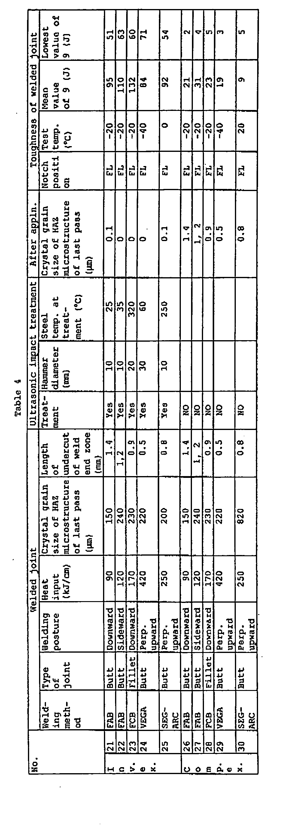
- Table 3 and Table 4 give examples corresponding to the third embodiment.
- Example Nos. 1 to 7 of the present invention when the ultrasonic impacts was carried out by an ultrasonic vibration tool having a pin diameter of ⁇ 10 to 30 mm, all of the crystal grain sizes of the HAZ microstructures (averages of longitudinal axis) adjacent to the fusion line and formed by the last welding pass (the welding pass in the vicinity of the toe in the case of the fillet welding) became 30 ⁇ m or less corresponding to the crystal grain size of the steel plate matrix before the welding up to the depth of 2 mm or more from the steel plate surface and as a result all exhibited high toughness values of 170J or more in average.
- the supplemental heating was carried out by the induction heating at the time of ultrasonic impacts.
- the toughness was evaluated by the Charpy impact absorption energy using the average value of nine test pieces.
- the test pieces were taken from the surface layer of the HAZ and stripped of the black skin of the surface.
- the notch positions were made the fusion lines (FL).
- the steel plate compositions other than Example No. 25 and No. 30 shown in Table 3 were made chemical compositions suppressing the coarsening of the crystal grain size due to the welding heat input by the pinning effect obtained by dispersing fine oxides such as Ca, Mg, etc.
- Example No. 12 to No. 25 of the present invention when ultrasonic impacts was carried out by an ultrasonic vibration tool having a pin diameter of ⁇ 10 to 30 mm, all undercut lengths of the toes became 0.1 mm or less. As a result, all exhibited high toughness values as the large heat input welding in average of 80J or more. Note that, in Example No. 23 and No. 25, the supplemental heating was carried out by induction heating at the time of the ultrasonic impacts.
- the toughness was evaluated by the Charpy impact absorption energy using the average value of nine test pieces.
- the test pieces were taken from the surface layer of the HAZ and stripped of the black skin of the surface.
- the notch positions were made the fusion lines (FL).
- Comparative Example No. 30 is not a steel plate for large heat input welding, therefore the average of longitudinal axis of crystal grains from the surface adjacent to the FL of the HAZ structure up to the depth of 2 mm or more is 800 ⁇ m or more and coarse and also undercut of the welding exists. Therefore, the Charpy absorption energy was an extremely low value of 9J even at a test temperature of +20°C.
- a method of improvement of toughness of a heat affected zone in a multi-layer welded joint, a fillet welded joint, or a one-pass or several-pass large heat input welded joint of a steel plate by subjecting the vicinity of a toe of a welded joint of a steel plate to impacts by an ultrasonic vibration tool or shot peening by ultrasonic vibration steel balls.
Landscapes
- Chemical & Material Sciences (AREA)
- Engineering & Computer Science (AREA)
- Mechanical Engineering (AREA)
- Organic Chemistry (AREA)
- Materials Engineering (AREA)
- Metallurgy (AREA)
- Crystallography & Structural Chemistry (AREA)
- Physics & Mathematics (AREA)
- Thermal Sciences (AREA)
- Butt Welding And Welding Of Specific Article (AREA)
- Heat Treatment Of Steel (AREA)
- Arc Welding In General (AREA)
- Heat Treatment Of Articles (AREA)
- Pressure Welding/Diffusion-Bonding (AREA)
Abstract
Description


Claims (5)
- A method of improvement of toughness of a heat affected zone in a welded joint of a steel plate characterized by subjecting a surface of a heat affected zone formed by a last pass of a multi-layer welded joint of a steel plate to impacts by an ultrasonic vibration tool or shot peening by ultrasonic vibration steel balls to thereby make an average of longitudinal axis of crystal grains up to a depth of 2 mm or more from the surface of the steel plate in the microstructure adjacent to a fusion line (FL) of a weld metal and a steel plate matrix in said heat affected zone formed by the last pass equivalent to the crystal grain size of the steel plate matrix before the welding at a depth of 1/4 of a thickness t from the surface of the steel plate.
- A method of improvement of toughness of a heat affected zone in a welded joint of a steel plate characterized by subjecting a vicinity of a toe portion of a fillet welded joint of a steel plate to impacts by an ultrasonic vibration tool or shot peening by ultrasonic vibration steel balls to thereby make an average of longitudinal axis of crystal grains up to a depth of 2 mm or more from the surface of the steel plate in the microstructure adjacent to a fusion line of a weld metal and a steel plate matrix in the heat affected zone in the vicinity of the toe portion equivalent to the crystal grain size of the steel plate matrix before the welding at a depth of 1/4 of a thickness t from the surface of the steel plate.
- A method of improvement of toughness of a heat affected zone in a welded joint of a steel plate as set forth in claim 1 or 2, characterized in that the average of longitudinal axis of crystal grains up to the depth of 2 mm or more from the surface of the steel plate is 30 µm or less.
- A method of improvement of toughness of a heat affected zone in a welded joint of a steel plate, characterized by subjecting a vicinity of a toe portion of a one-pass or several-pass large heat input welded joint of the steel plate to impacts by an ultrasonic vibration tool or shot peening by ultrasonic vibration steel balls to thereby make a length of an undercut formed in said toe portion 0.3 mm or less.
- A method of improvement of toughness of a heat affected zone in a welded joint of a steel material as set forth in any one of claims 1 to 4, characterized by supplemental heating said steel plate before or during the impacts by the ultrasonic vibration tool or the shot peening by the ultrasonic vibration steel balls.
Priority Applications (1)
| Application Number | Priority Date | Filing Date | Title |
|---|---|---|---|
| EP17156912.2A EP3199648A1 (en) | 2002-10-30 | 2003-10-29 | Method of improvement of toughness of heat affected zone at welded joint of steel plate |
Applications Claiming Priority (3)
| Application Number | Priority Date | Filing Date | Title |
|---|---|---|---|
| JP2002315396 | 2002-10-30 | ||
| JP2002315396A JP4189201B2 (en) | 2002-10-30 | 2002-10-30 | Method for improving toughness of heat-affected zone in steel welded joints |
| PCT/JP2003/013875 WO2004040023A1 (en) | 2002-10-30 | 2003-10-29 | Method of increasing toughness of heat-affected part of steel product welded joint |
Related Child Applications (2)
| Application Number | Title | Priority Date | Filing Date |
|---|---|---|---|
| EP17156912.2A Division EP3199648A1 (en) | 2002-10-30 | 2003-10-29 | Method of improvement of toughness of heat affected zone at welded joint of steel plate |
| EP17156912.2A Division-Into EP3199648A1 (en) | 2002-10-30 | 2003-10-29 | Method of improvement of toughness of heat affected zone at welded joint of steel plate |
Publications (3)
| Publication Number | Publication Date |
|---|---|
| EP1559796A1 true EP1559796A1 (en) | 2005-08-03 |
| EP1559796A4 EP1559796A4 (en) | 2006-06-21 |
| EP1559796B1 EP1559796B1 (en) | 2017-04-19 |
Family
ID=32211651
Family Applications (2)
| Application Number | Title | Priority Date | Filing Date |
|---|---|---|---|
| EP03769982.4A Expired - Lifetime EP1559796B1 (en) | 2002-10-30 | 2003-10-29 | Method of increasing toughness of heat-affected part of steel product welded joint |
| EP17156912.2A Withdrawn EP3199648A1 (en) | 2002-10-30 | 2003-10-29 | Method of improvement of toughness of heat affected zone at welded joint of steel plate |
Family Applications After (1)
| Application Number | Title | Priority Date | Filing Date |
|---|---|---|---|
| EP17156912.2A Withdrawn EP3199648A1 (en) | 2002-10-30 | 2003-10-29 | Method of improvement of toughness of heat affected zone at welded joint of steel plate |
Country Status (8)
| Country | Link |
|---|---|
| US (1) | US7754033B2 (en) |
| EP (2) | EP1559796B1 (en) |
| JP (1) | JP4189201B2 (en) |
| KR (1) | KR100671037B1 (en) |
| CN (1) | CN100523230C (en) |
| AU (1) | AU2003280611A1 (en) |
| ES (1) | ES2624352T3 (en) |
| WO (1) | WO2004040023A1 (en) |
Cited By (5)
| Publication number | Priority date | Publication date | Assignee | Title |
|---|---|---|---|---|
| WO2006111829A1 (en) * | 2005-04-19 | 2006-10-26 | Aibel As | Method for obtaining enhanced fatigue strength in welded metal joints and hammer head for use at cold working |
| WO2010086146A1 (en) * | 2009-01-27 | 2010-08-05 | Fraunhofer-Gesellschaft zur Förderung der angewandten Forschung e.V. | Method for joining at least two metal components |
| AU2009277618B2 (en) * | 2008-07-28 | 2012-06-21 | Nippon Steel Corporation | Peening method for improving the fatigue characteristics of a welded joint, peening apparatus for improving the fatigue characteristics, and welded structure having excellent anti-fatigue characteristics |
| EP2787089A1 (en) * | 2013-04-04 | 2014-10-08 | MTU Aero Engines GmbH | Method and device for processing containers |
| CZ308308B6 (en) * | 2019-01-23 | 2020-04-29 | Pilsen Tools S.R.O. | A method of producing an ultrasonic welding tool for electrically conductive as well as non-conductive materials and a tool produced in this way |
Families Citing this family (34)
| Publication number | Priority date | Publication date | Assignee | Title |
|---|---|---|---|---|
| US20050145306A1 (en) * | 1998-09-03 | 2005-07-07 | Uit, L.L.C. Company | Welded joints with new properties and provision of such properties by ultrasonic impact treatment |
| US6338765B1 (en) | 1998-09-03 | 2002-01-15 | Uit, L.L.C. | Ultrasonic impact methods for treatment of welded structures |
| US6932876B1 (en) | 1998-09-03 | 2005-08-23 | U.I.T., L.L.C. | Ultrasonic impact machining of body surfaces to correct defects and strengthen work surfaces |
| GB0129968D0 (en) | 2001-12-14 | 2002-02-06 | Nel Technologies Ltd | Flexible heater |
| US7301123B2 (en) | 2004-04-29 | 2007-11-27 | U.I.T., L.L.C. | Method for modifying or producing materials and joints with specific properties by generating and applying adaptive impulses a normalizing energy thereof and pauses therebetween |
| JP4695355B2 (en) * | 2004-07-15 | 2011-06-08 | 新日本製鐵株式会社 | Boom / arm member for construction machine with excellent weld fatigue strength and method for manufacturing the same |
| BRPI0403851A (en) * | 2004-08-31 | 2007-02-21 | Global Welding Tecnologia Ltda | electric welding process of low and high alloy steels, hardened or not, and bimetals, to obtain a determined texture without heat treatment |
| US7276824B2 (en) | 2005-08-19 | 2007-10-02 | U.I.T., L.L.C. | Oscillating system and tool for ultrasonic impact treatment |
| DE102005054866A1 (en) * | 2005-11-17 | 2007-05-31 | Mtu Aero Engines Gmbh | Method for producing metallic components, in particular for turbomachinery, with small edge radii |
| JP4865334B2 (en) | 2006-01-10 | 2012-02-01 | 三菱重工業株式会社 | Tip tool guide device and method for loading tip tool guide device |
| TWI396600B (en) * | 2009-08-24 | 2013-05-21 | Nippon Steel & Sumitomo Metal Corp | Out-of-plane gusset weld joints and manufacturing method therefor |
| CN102470489A (en) * | 2009-11-07 | 2012-05-23 | 新日本制铁株式会社 | Multiple peening treatment method for weld toe section |
| EP2508291B1 (en) * | 2009-12-04 | 2017-05-03 | Nippon Steel & Sumitomo Metal Corporation | Butt-welded joint formed using electron beam |
| ES2542743T3 (en) * | 2009-12-04 | 2015-08-11 | Nippon Steel & Sumitomo Metal Corporation | Welded structure with a butt welded joint and method for manufacturing |
| JP5543261B2 (en) * | 2010-04-14 | 2014-07-09 | 株式会社Ihi | Ultrasonic peening construction method |
| CN102152012B (en) * | 2011-01-25 | 2013-06-05 | 武汉科技大学 | Online process for improving impact toughness of welding heat affected zone |
| US9605328B2 (en) * | 2011-07-29 | 2017-03-28 | Progress Rail Services Corporation | Surface contouring of a weld cap and adjacent base metal using ultrasonic impact treatment |
| JP2013071140A (en) * | 2011-09-27 | 2013-04-22 | Nippon Steel & Sumitomo Metal Corp | Welded joint excellent in fatigue resistance and method for manufacturing the same |
| JP5880032B2 (en) * | 2011-12-27 | 2016-03-08 | トヨタ自動車株式会社 | Laser welding method |
| US20140255620A1 (en) * | 2013-03-06 | 2014-09-11 | Rolls-Royce Corporation | Sonic grain refinement of laser deposits |
| US20140374156A1 (en) * | 2013-06-19 | 2014-12-25 | Smith International, Inc. | Methods of reducing stress in downhole tools |
| US10391574B2 (en) * | 2013-12-16 | 2019-08-27 | Huys Industries Limited | Welding method and apparatus therefor |
| KR101634167B1 (en) | 2015-04-30 | 2016-06-30 | 주식회사 포스코 | Multi-layer welding method |
| CN105195860B (en) * | 2015-09-17 | 2018-09-07 | 中建钢构有限公司 | Welding method is tiltedly found in back docking |
| FR3054154B1 (en) * | 2016-07-21 | 2019-05-10 | Europe Technologies | ROBOTISE DRYING METHOD AND ROBOTIC SYSTEM FOR IMPLEMENTING THE METHOD |
| CN107052534A (en) * | 2017-01-12 | 2017-08-18 | 南京工程学院 | A kind of synchronous shot-peening magnesium alloy welding device and method |
| CN106811584A (en) * | 2017-03-31 | 2017-06-09 | 江苏瑞格新材料有限公司 | A kind of alloyed steel surface strengthening device |
| KR102301089B1 (en) * | 2017-06-27 | 2021-09-09 | 지멘스 에너지, 인코포레이티드 | Methods and apparatus for welding using electrodes having a coaxial power feed |
| JP6696604B1 (en) * | 2019-03-08 | 2020-05-20 | Jfeスチール株式会社 | Needle peening method |
| US20200300818A1 (en) * | 2019-03-20 | 2020-09-24 | University Of Louisville Research Foundation, Inc. | High-frequency oscillatory plastic deformation based solid-state material deposition for metal surface repair |
| CN110280884B (en) * | 2019-07-29 | 2020-12-22 | 吉林大学 | Ultrasonic impact toughening joint with groove added with alloy powder |
| CN111334660B (en) * | 2020-03-16 | 2021-12-03 | 中沃(泰州)激光科技有限公司 | Welding bead residual stress relieving device and method |
| CN111575474B (en) * | 2020-04-13 | 2021-10-12 | 江苏大学 | Thermal torsional vibration composite aging method and device for escalator driving main shaft |
| WO2021207838A1 (en) | 2020-04-14 | 2021-10-21 | Huys Industries Limited | Welded assembly and method of welding using electro-spark discharge |
Family Cites Families (14)
| Publication number | Priority date | Publication date | Assignee | Title |
|---|---|---|---|---|
| JPS5322843A (en) | 1976-08-13 | 1978-03-02 | Nippon Steel Corp | Method of improving solidification structure of weld zone by use of ultrasonic oscillatory radiation |
| JPS53123346A (en) * | 1977-04-04 | 1978-10-27 | Mitsubishi Heavy Ind Ltd | Treating method for toe of weld |
| JPS6479320A (en) * | 1987-09-19 | 1989-03-24 | Nippon Steel Corp | Improvement of material quality of metal for welding austenitic stainless steel |
| JPH08174422A (en) | 1994-12-27 | 1996-07-09 | Toshiba Corp | Surface modification method for internal structure of nuclear reactor |
| JP3386931B2 (en) | 1995-06-28 | 2003-03-17 | 株式会社日立製作所 | Method of welding water turbine members |
| JP3408687B2 (en) * | 1996-02-29 | 2003-05-19 | 三菱重工業株式会社 | Welding equipment with welding residual stress reduction device |
| US6932876B1 (en) * | 1998-09-03 | 2005-08-23 | U.I.T., L.L.C. | Ultrasonic impact machining of body surfaces to correct defects and strengthen work surfaces |
| US6171415B1 (en) * | 1998-09-03 | 2001-01-09 | Uit, Llc | Ultrasonic impact methods for treatment of welded structures |
| US6338765B1 (en) * | 1998-09-03 | 2002-01-15 | Uit, L.L.C. | Ultrasonic impact methods for treatment of welded structures |
| US6223974B1 (en) * | 1999-10-13 | 2001-05-01 | Madhavji A. Unde | Trailing edge stress relief process (TESR) for welds |
| US6467321B2 (en) * | 2000-05-30 | 2002-10-22 | Integrity Testing Laboratory, Inc. | Device for ultrasonic peening of metals |
| FR2812284B1 (en) * | 2000-07-28 | 2003-03-07 | Univ Troyes Technologie | MECHANICAL METHOD FOR GENERATING NANOSTRUCTURES AND MECHANICAL DEVICE FOR GENERATING NANOSTRUCTURES |
| FR2816538B1 (en) | 2000-11-16 | 2003-01-17 | Snecma Moteurs | PROCESS FOR INCREASING THE LIFETIME OF AUB ATTACHES ON A ROTOR |
| JP2003113418A (en) * | 2001-10-04 | 2003-04-18 | Nippon Steel Corp | Fatigue life improvement treatment method and long life metal material by it |
-
2002
- 2002-10-30 JP JP2002315396A patent/JP4189201B2/en not_active Expired - Fee Related
-
2003
- 2003-10-29 WO PCT/JP2003/013875 patent/WO2004040023A1/en not_active Ceased
- 2003-10-29 CN CNB2003801021927A patent/CN100523230C/en not_active Expired - Fee Related
- 2003-10-29 ES ES03769982.4T patent/ES2624352T3/en not_active Expired - Lifetime
- 2003-10-29 US US10/533,607 patent/US7754033B2/en not_active Expired - Fee Related
- 2003-10-29 KR KR1020057007741A patent/KR100671037B1/en not_active Expired - Fee Related
- 2003-10-29 EP EP03769982.4A patent/EP1559796B1/en not_active Expired - Lifetime
- 2003-10-29 AU AU2003280611A patent/AU2003280611A1/en not_active Abandoned
- 2003-10-29 EP EP17156912.2A patent/EP3199648A1/en not_active Withdrawn
Cited By (7)
| Publication number | Priority date | Publication date | Assignee | Title |
|---|---|---|---|---|
| WO2006111829A1 (en) * | 2005-04-19 | 2006-10-26 | Aibel As | Method for obtaining enhanced fatigue strength in welded metal joints and hammer head for use at cold working |
| AU2009277618B2 (en) * | 2008-07-28 | 2012-06-21 | Nippon Steel Corporation | Peening method for improving the fatigue characteristics of a welded joint, peening apparatus for improving the fatigue characteristics, and welded structure having excellent anti-fatigue characteristics |
| US8776564B2 (en) | 2008-07-28 | 2014-07-15 | Nippon Steel & Sumitomo Metal Corporation | Impact treatment method for improving fatigue characteristics of welded joint, impact treatment device for improving fatigue characteristics for same, and welded structure superior in fatigue resistance characteristics |
| WO2010086146A1 (en) * | 2009-01-27 | 2010-08-05 | Fraunhofer-Gesellschaft zur Förderung der angewandten Forschung e.V. | Method for joining at least two metal components |
| EP2787089A1 (en) * | 2013-04-04 | 2014-10-08 | MTU Aero Engines GmbH | Method and device for processing containers |
| WO2014161650A1 (en) * | 2013-04-04 | 2014-10-09 | MTU Aero Engines AG | Device and method for the treatment of components |
| CZ308308B6 (en) * | 2019-01-23 | 2020-04-29 | Pilsen Tools S.R.O. | A method of producing an ultrasonic welding tool for electrically conductive as well as non-conductive materials and a tool produced in this way |
Also Published As
| Publication number | Publication date |
|---|---|
| JP2004149843A (en) | 2004-05-27 |
| EP3199648A1 (en) | 2017-08-02 |
| CN1708593A (en) | 2005-12-14 |
| ES2624352T3 (en) | 2017-07-13 |
| KR20050065665A (en) | 2005-06-29 |
| CN100523230C (en) | 2009-08-05 |
| JP4189201B2 (en) | 2008-12-03 |
| EP1559796B1 (en) | 2017-04-19 |
| KR100671037B1 (en) | 2007-01-19 |
| US7754033B2 (en) | 2010-07-13 |
| AU2003280611A1 (en) | 2004-05-25 |
| EP1559796A4 (en) | 2006-06-21 |
| WO2004040023A1 (en) | 2004-05-13 |
| US20060137777A1 (en) | 2006-06-29 |
Similar Documents
| Publication | Publication Date | Title |
|---|---|---|
| EP1559796A1 (en) | Method of increasing toughness of heat-affected part of steel product welded joint | |
| KR101134158B1 (en) | Welded joint with excellent fatigue-resistance characteristics, and method for producing same | |
| TWI396600B (en) | Out-of-plane gusset weld joints and manufacturing method therefor | |
| EP1775391B1 (en) | Method of improvement of the weld zone fatigue strength of a boom and arm member of a construction machine. | |
| KR100606312B1 (en) | Boxing joint with excellent fatigue strength, method of manufacturing the boxing joint, and welded structure | |
| CN115243825A (en) | Methods of welding coated steel sheets | |
| DE102008028996B4 (en) | Process for the aftertreatment of a welded joint | |
| JP2004169339A (en) | Rail reinforcement and repair method | |
| JPH07118757A (en) | Laser heating method for structural steel with excellent joint fatigue strength | |
| JP3840172B2 (en) | UOE steel pipe manufacturing method with excellent HAZ toughness | |
| JP4709697B2 (en) | Method for improving fatigue strength of metal lap weld joints | |
| JP2002248569A (en) | Method of manufacturing steel welded joints for welded structures with excellent fatigue strength | |
| JPH0819860A (en) | Welding method for structural steel turn welded joints | |
| JP3900490B2 (en) | Fatigue reinforcement method for girders with flange gussets | |
| Chen et al. | Welding thin plate of 400 MPa grade ultra-fine grained steel using CO sub 2 laser | |
| Peng et al. | Laser Welding of Ultra-Fine Grained Steel SS 400. | |
| JP2000167675A (en) | High frequency resistance welding method and welded section steel |
Legal Events
| Date | Code | Title | Description |
|---|---|---|---|
| PUAI | Public reference made under article 153(3) epc to a published international application that has entered the european phase |
Free format text: ORIGINAL CODE: 0009012 |
|
| 17P | Request for examination filed |
Effective date: 20050527 |
|
| AK | Designated contracting states |
Kind code of ref document: A1 Designated state(s): AT BE BG CH CY CZ DE DK EE ES FI FR GB GR HU IE IT LI LU MC NL PT RO SE SI SK TR |
|
| AX | Request for extension of the european patent |
Extension state: AL LT LV MK |
|
| DAX | Request for extension of the european patent (deleted) | ||
| A4 | Supplementary search report drawn up and despatched |
Effective date: 20060523 |
|
| 17Q | First examination report despatched |
Effective date: 20100707 |
|
| RAP1 | Party data changed (applicant data changed or rights of an application transferred) |
Owner name: NIPPON STEEL & SUMITOMO METAL CORPORATION |
|
| REG | Reference to a national code |
Ref country code: DE Ref legal event code: R079 Ref document number: 60350141 Country of ref document: DE Free format text: PREVIOUS MAIN CLASS: C21D0007060000 Ipc: B23K0020100000 |
|
| GRAP | Despatch of communication of intention to grant a patent |
Free format text: ORIGINAL CODE: EPIDOSNIGR1 |
|
| RIC1 | Information provided on ipc code assigned before grant |
Ipc: C21D 7/06 20060101ALI20160926BHEP Ipc: C21D 9/50 20060101ALI20160926BHEP Ipc: B23K 20/10 20060101AFI20160926BHEP Ipc: B23K 103/04 20060101ALI20160926BHEP Ipc: C21D 10/00 20060101ALI20160926BHEP Ipc: B23K 33/00 20060101ALI20160926BHEP Ipc: C21D 7/04 20060101ALI20160926BHEP |
|
| INTG | Intention to grant announced |
Effective date: 20161014 |
|
| GRAS | Grant fee paid |
Free format text: ORIGINAL CODE: EPIDOSNIGR3 |
|
| GRAA | (expected) grant |
Free format text: ORIGINAL CODE: 0009210 |
|
| AK | Designated contracting states |
Kind code of ref document: B1 Designated state(s): AT BE BG CH CY CZ DE DK EE ES FI FR GB GR HU IE IT LI LU MC NL PT RO SE SI SK TR |
|
| REG | Reference to a national code |
Ref country code: GB Ref legal event code: FG4D |
|
| REG | Reference to a national code |
Ref country code: CH Ref legal event code: EP |
|
| REG | Reference to a national code |
Ref country code: DE Ref legal event code: R081 Ref document number: 60350141 Country of ref document: DE Owner name: NIPPON STEEL CORPORATION, JP Free format text: FORMER OWNER: NIPPON STEEL CORP., TOKIO/TOKYO, JP |
|
| REG | Reference to a national code |
Ref country code: AT Ref legal event code: REF Ref document number: 885482 Country of ref document: AT Kind code of ref document: T Effective date: 20170515 |
|
| REG | Reference to a national code |
Ref country code: NL Ref legal event code: FP Ref country code: IE Ref legal event code: FG4D |
|
| REG | Reference to a national code |
Ref country code: DE Ref legal event code: R096 Ref document number: 60350141 Country of ref document: DE |
|
| REG | Reference to a national code |
Ref country code: SE Ref legal event code: TRGR |
|
| REG | Reference to a national code |
Ref country code: ES Ref legal event code: FG2A Ref document number: 2624352 Country of ref document: ES Kind code of ref document: T3 Effective date: 20170713 |
|
| REG | Reference to a national code |
Ref country code: FR Ref legal event code: PLFP Year of fee payment: 15 |
|
| REG | Reference to a national code |
Ref country code: AT Ref legal event code: MK05 Ref document number: 885482 Country of ref document: AT Kind code of ref document: T Effective date: 20170419 |
|
| PG25 | Lapsed in a contracting state [announced via postgrant information from national office to epo] |
Ref country code: AT Free format text: LAPSE BECAUSE OF FAILURE TO SUBMIT A TRANSLATION OF THE DESCRIPTION OR TO PAY THE FEE WITHIN THE PRESCRIBED TIME-LIMIT Effective date: 20170419 Ref country code: GR Free format text: LAPSE BECAUSE OF FAILURE TO SUBMIT A TRANSLATION OF THE DESCRIPTION OR TO PAY THE FEE WITHIN THE PRESCRIBED TIME-LIMIT Effective date: 20170720 |
|
| PG25 | Lapsed in a contracting state [announced via postgrant information from national office to epo] |
Ref country code: BG Free format text: LAPSE BECAUSE OF FAILURE TO SUBMIT A TRANSLATION OF THE DESCRIPTION OR TO PAY THE FEE WITHIN THE PRESCRIBED TIME-LIMIT Effective date: 20170719 |
|
| REG | Reference to a national code |
Ref country code: DE Ref legal event code: R097 Ref document number: 60350141 Country of ref document: DE |
|
| PG25 | Lapsed in a contracting state [announced via postgrant information from national office to epo] |
Ref country code: RO Free format text: LAPSE BECAUSE OF FAILURE TO SUBMIT A TRANSLATION OF THE DESCRIPTION OR TO PAY THE FEE WITHIN THE PRESCRIBED TIME-LIMIT Effective date: 20170419 Ref country code: EE Free format text: LAPSE BECAUSE OF FAILURE TO SUBMIT A TRANSLATION OF THE DESCRIPTION OR TO PAY THE FEE WITHIN THE PRESCRIBED TIME-LIMIT Effective date: 20170419 Ref country code: DK Free format text: LAPSE BECAUSE OF FAILURE TO SUBMIT A TRANSLATION OF THE DESCRIPTION OR TO PAY THE FEE WITHIN THE PRESCRIBED TIME-LIMIT Effective date: 20170419 Ref country code: SK Free format text: LAPSE BECAUSE OF FAILURE TO SUBMIT A TRANSLATION OF THE DESCRIPTION OR TO PAY THE FEE WITHIN THE PRESCRIBED TIME-LIMIT Effective date: 20170419 |
|
| PLBE | No opposition filed within time limit |
Free format text: ORIGINAL CODE: 0009261 |
|
| STAA | Information on the status of an ep patent application or granted ep patent |
Free format text: STATUS: NO OPPOSITION FILED WITHIN TIME LIMIT |
|
| 26N | No opposition filed |
Effective date: 20180122 |
|
| PG25 | Lapsed in a contracting state [announced via postgrant information from national office to epo] |
Ref country code: MC Free format text: LAPSE BECAUSE OF FAILURE TO SUBMIT A TRANSLATION OF THE DESCRIPTION OR TO PAY THE FEE WITHIN THE PRESCRIBED TIME-LIMIT Effective date: 20170419 Ref country code: SI Free format text: LAPSE BECAUSE OF FAILURE TO SUBMIT A TRANSLATION OF THE DESCRIPTION OR TO PAY THE FEE WITHIN THE PRESCRIBED TIME-LIMIT Effective date: 20170419 |
|
| REG | Reference to a national code |
Ref country code: CH Ref legal event code: PL |
|
| REG | Reference to a national code |
Ref country code: IE Ref legal event code: MM4A |
|
| PG25 | Lapsed in a contracting state [announced via postgrant information from national office to epo] |
Ref country code: LU Free format text: LAPSE BECAUSE OF NON-PAYMENT OF DUE FEES Effective date: 20171029 Ref country code: CH Free format text: LAPSE BECAUSE OF NON-PAYMENT OF DUE FEES Effective date: 20171031 Ref country code: LI Free format text: LAPSE BECAUSE OF NON-PAYMENT OF DUE FEES Effective date: 20171031 |
|
| REG | Reference to a national code |
Ref country code: FR Ref legal event code: PLFP Year of fee payment: 16 |
|
| PG25 | Lapsed in a contracting state [announced via postgrant information from national office to epo] |
Ref country code: IE Free format text: LAPSE BECAUSE OF NON-PAYMENT OF DUE FEES Effective date: 20171029 |
|
| REG | Reference to a national code |
Ref country code: DE Ref legal event code: R082 Ref document number: 60350141 Country of ref document: DE Representative=s name: VOSSIUS & PARTNER PATENTANWAELTE RECHTSANWAELT, DE Ref country code: DE Ref legal event code: R081 Ref document number: 60350141 Country of ref document: DE Owner name: NIPPON STEEL CORPORATION, JP Free format text: FORMER OWNER: NIPPON STEEL & SUMITOMO METAL CORPORATION, TOKYO, JP |
|
| PG25 | Lapsed in a contracting state [announced via postgrant information from national office to epo] |
Ref country code: HU Free format text: LAPSE BECAUSE OF FAILURE TO SUBMIT A TRANSLATION OF THE DESCRIPTION OR TO PAY THE FEE WITHIN THE PRESCRIBED TIME-LIMIT; INVALID AB INITIO Effective date: 20031029 |
|
| PG25 | Lapsed in a contracting state [announced via postgrant information from national office to epo] |
Ref country code: CY Free format text: LAPSE BECAUSE OF NON-PAYMENT OF DUE FEES Effective date: 20170419 |
|
| PGFP | Annual fee paid to national office [announced via postgrant information from national office to epo] |
Ref country code: NL Payment date: 20190912 Year of fee payment: 17 Ref country code: FR Payment date: 20190913 Year of fee payment: 17 |
|
| PGFP | Annual fee paid to national office [announced via postgrant information from national office to epo] |
Ref country code: BE Payment date: 20190917 Year of fee payment: 17 |
|
| PGFP | Annual fee paid to national office [announced via postgrant information from national office to epo] |
Ref country code: SE Payment date: 20191010 Year of fee payment: 17 Ref country code: FI Payment date: 20191009 Year of fee payment: 17 Ref country code: CZ Payment date: 20191024 Year of fee payment: 17 Ref country code: DE Payment date: 20191015 Year of fee payment: 17 |
|
| PGFP | Annual fee paid to national office [announced via postgrant information from national office to epo] |
Ref country code: IT Payment date: 20191009 Year of fee payment: 17 Ref country code: ES Payment date: 20191104 Year of fee payment: 17 |
|
| PG25 | Lapsed in a contracting state [announced via postgrant information from national office to epo] |
Ref country code: TR Free format text: LAPSE BECAUSE OF FAILURE TO SUBMIT A TRANSLATION OF THE DESCRIPTION OR TO PAY THE FEE WITHIN THE PRESCRIBED TIME-LIMIT Effective date: 20170419 |
|
| PGFP | Annual fee paid to national office [announced via postgrant information from national office to epo] |
Ref country code: GB Payment date: 20191025 Year of fee payment: 17 |
|
| PG25 | Lapsed in a contracting state [announced via postgrant information from national office to epo] |
Ref country code: PT Free format text: LAPSE BECAUSE OF FAILURE TO SUBMIT A TRANSLATION OF THE DESCRIPTION OR TO PAY THE FEE WITHIN THE PRESCRIBED TIME-LIMIT Effective date: 20170419 |
|
| REG | Reference to a national code |
Ref country code: DE Ref legal event code: R119 Ref document number: 60350141 Country of ref document: DE |
|
| REG | Reference to a national code |
Ref country code: FI Ref legal event code: MAE |
|
| REG | Reference to a national code |
Ref country code: SE Ref legal event code: EUG |
|
| REG | Reference to a national code |
Ref country code: NL Ref legal event code: MM Effective date: 20201101 |
|
| GBPC | Gb: european patent ceased through non-payment of renewal fee |
Effective date: 20201029 |
|
| REG | Reference to a national code |
Ref country code: BE Ref legal event code: MM Effective date: 20201031 |
|
| PG25 | Lapsed in a contracting state [announced via postgrant information from national office to epo] |
Ref country code: FR Free format text: LAPSE BECAUSE OF NON-PAYMENT OF DUE FEES Effective date: 20201031 Ref country code: FI Free format text: LAPSE BECAUSE OF NON-PAYMENT OF DUE FEES Effective date: 20201029 Ref country code: DE Free format text: LAPSE BECAUSE OF NON-PAYMENT OF DUE FEES Effective date: 20210501 Ref country code: CZ Free format text: LAPSE BECAUSE OF NON-PAYMENT OF DUE FEES Effective date: 20201029 Ref country code: NL Free format text: LAPSE BECAUSE OF NON-PAYMENT OF DUE FEES Effective date: 20201101 |
|
| PG25 | Lapsed in a contracting state [announced via postgrant information from national office to epo] |
Ref country code: BE Free format text: LAPSE BECAUSE OF NON-PAYMENT OF DUE FEES Effective date: 20201031 Ref country code: SE Free format text: LAPSE BECAUSE OF NON-PAYMENT OF DUE FEES Effective date: 20201030 Ref country code: GB Free format text: LAPSE BECAUSE OF NON-PAYMENT OF DUE FEES Effective date: 20201029 |
|
| PG25 | Lapsed in a contracting state [announced via postgrant information from national office to epo] |
Ref country code: IT Free format text: LAPSE BECAUSE OF NON-PAYMENT OF DUE FEES Effective date: 20201029 |
|
| REG | Reference to a national code |
Ref country code: ES Ref legal event code: FD2A Effective date: 20220128 |
|
| PG25 | Lapsed in a contracting state [announced via postgrant information from national office to epo] |
Ref country code: ES Free format text: LAPSE BECAUSE OF NON-PAYMENT OF DUE FEES Effective date: 20201030 |