EP1559644A2 - Poignée de levage en particulier pour bicyclettes - Google Patents
Poignée de levage en particulier pour bicyclettes Download PDFInfo
- Publication number
- EP1559644A2 EP1559644A2 EP05445004A EP05445004A EP1559644A2 EP 1559644 A2 EP1559644 A2 EP 1559644A2 EP 05445004 A EP05445004 A EP 05445004A EP 05445004 A EP05445004 A EP 05445004A EP 1559644 A2 EP1559644 A2 EP 1559644A2
- Authority
- EP
- European Patent Office
- Prior art keywords
- fixing
- handle
- fixing part
- tube
- lifting handle
- Prior art date
- Legal status (The legal status is an assumption and is not a legal conclusion. Google has not performed a legal analysis and makes no representation as to the accuracy of the status listed.)
- Withdrawn
Links
- 230000000284 resting effect Effects 0.000 claims abstract description 3
- 230000015572 biosynthetic process Effects 0.000 claims description 8
- 238000005452 bending Methods 0.000 claims description 2
- 238000004519 manufacturing process Methods 0.000 description 1
- 239000003973 paint Substances 0.000 description 1
Images


Classifications
-
- B—PERFORMING OPERATIONS; TRANSPORTING
- B62—LAND VEHICLES FOR TRAVELLING OTHERWISE THAN ON RAILS
- B62J—CYCLE SADDLES OR SEATS; AUXILIARY DEVICES OR ACCESSORIES SPECIALLY ADAPTED TO CYCLES AND NOT OTHERWISE PROVIDED FOR, e.g. ARTICLE CARRIERS OR CYCLE PROTECTORS
- B62J50/00—Arrangements specially adapted for use on cycles not provided for in main groups B62J1/00 - B62J45/00
- B62J50/10—Means for carrying cycles by hand
Definitions
- the present invention relates to a lifting handle which is specially adapted for bicycles and which comprises a fixing part for releasable mounting to a tube part and a handle pivotably connected to the fixing part.
- the lifting handles which today are common on the market are integrally designed with the bicycle or the vehicle in question or the two wheel vehicle which is intended to be lifted and this type of handles are spring biased in a way so that when they are not in use the lie parallel with the tube part of the vehicle which it is fixed to and when it is to be lifted said handle is swingable upwards against the bias of the spring to a substantially horizontal position, whereafter the bicycle may be lifted by manual power.
- the object of the present invention is now to provide a new type of lifting handle for especially bicycles and the like two wheel vehicles where the lifting handle is mountable later on, i.e. is mobile, and which may be fastened on a suitable position on a tube part without free ends and then preferably at a position on the tube part which is centrally positioned in order to achieve a balance when lifting.
- the lifting handle is mountable later on, i.e. is mobile, and which may be fastened on a suitable position on a tube part without free ends and then preferably at a position on the tube part which is centrally positioned in order to achieve a balance when lifting.
- a mobile lifting handle especially for bicycles is now provided, which in an excellent way fulfils its purposes at the same time as it is inexpensive to manufacture as well. Thanks to the flexibility of the lifting handle and its fixing arrangement it may be fixed to tube parts of different dimensions and the lifting handle moreover shows few parts without sprint and is after the fixing self locking. Further the fixing means used for fixation of the lifting handle at the frame part of the bicycle is adjustable without protruding parts.
- a lifting handle 1 of the invention which is especially adapted for bicycles and which comprises a fixing part 2 for releasable fixing to a tube part 3.
- a handle 4 pivotally articulated at the fixing part 2, is mountable in the unfixed position to the fixing part 2 for pivotable articulation around the same.
- the fixing part 2 thus shows a protrusion 6 provided with a pivot pin protruding from an abutment portion 5 which is conically formed and cooperating with the tube part 3.
- a pivot pin 7 present on the protrusion 6 is adapted to take up the handle 4 and after the mounting of the handle 4 over the pivot pin 7 it is pivotable around it from a resting position along the tube part 3 in question to a using or functional position in an angled position out from the tube part 3.
- the protrusion 6 provided with a pivot pin is with its pivot pin 7 adapted to take up the handle 4 after the fixing of the lifting handle 1 to the tube part 3 at the same time as it shows a hook formation 8, which is partly delimited by a groove counter sink 9 whose width and depth substantially corresponds to the diameter and thickness of the pivot pin 7.
- the fixing part 2 shows a centrally arranged recess 10 whose bending corresponds to and is adapted to cooperate with the hook formation 8 of the handle 4 when upwardly pivoting the handle 4 to its using position.
- the bent recess 10 of the fixing part 2 is this adapted to cooperate with the hook formation 8 of the handle 4 and the depth of the recess 10 in the fixing part 2 is adapted to receive the hook formation 8 fully for positional fixing of the handle 4 in an upwardly pivoted, predetermined angle, which corresponds to the using position of the handle 4, which is substantially horizontal.
- the fixing part 2 shows in the vicinity of the abutment portion 5 a through going slot 11 for cooperation with a fixing means 12 which comprises an adjustable strap 13, which fixes the fixing part 2 to the tube part 3.
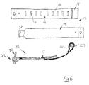
- the fixing means 12, as is evident from Fig. 6, is a strap 13, which is divided in two and adjustably settable relative the dimension of the tube part 3 in question.
- the strap 13 thus comprises two main parts, namely a first strap part 14 and a second strap part 15, which are lockably cooperating with each other in order to fix the fixing means so that they can be applicable to different tube part dimensions.
- the strap parts 14, 15 are thus adapted to cooperate with the slot 11 in the fixing part 2 and are by means of the conically designed abutment portion 5 of the fixing part 2 fixable in a suitable position at the tube portion 3.
- Both of the strap parts 14 and 15 are thus adjustably cooperatable with each other by means of a locking tongue 17 present on the first strap part 14, which tongue in turn is adapted to lock in a selectable position along the second strap part 15 in locking holes 16 present after each other at predetermined distances.
- the second strap part 15 comprises two parts, namely a first part 18, which shows the holes 16 and a second, underlying part 19, which latter is adapted to directly abut the tube part 3 and protect it from fixing marks, when the locking tongue 17 is fixed in position in desired locking hole 16. As is shown in more detail in the lower part of Fig.
- both of the strap parts 14 and 15 are in fixed position relative each other and here it shows in more detail that the locking tongue 17 is present in its locking position in a locking hole 16 and that the locking tongue 17 then is positioned between the second part 19 and the first part 18 of the second strap part 15.
- locking means in the form of a fixing screw 20 and a fixing nut 21 cooperating with the screw 20 arranged at the outer ends 22 and 23 of the strap parts 14 and 15.
- the fixing means 12 may also be supplemented with a rubber strip in order not to damage the paint work at the tube part 3 and thus further protect the paintwork at the tube part 3.
Landscapes
- Engineering & Computer Science (AREA)
- Mechanical Engineering (AREA)
- Steering Devices For Bicycles And Motorcycles (AREA)
Applications Claiming Priority (2)
| Application Number | Priority Date | Filing Date | Title |
|---|---|---|---|
| SE0400189 | 2004-01-30 | ||
| SE0400189A SE526398C2 (sv) | 2004-01-30 | 2004-01-30 | Lyfthandtag särskilt avsett för cyklar |
Publications (2)
| Publication Number | Publication Date |
|---|---|
| EP1559644A2 true EP1559644A2 (fr) | 2005-08-03 |
| EP1559644A3 EP1559644A3 (fr) | 2009-02-18 |
Family
ID=31713257
Family Applications (1)
| Application Number | Title | Priority Date | Filing Date |
|---|---|---|---|
| EP05445004A Withdrawn EP1559644A3 (fr) | 2004-01-30 | 2005-01-24 | Poignée de levage en particulier pour bicyclettes |
Country Status (2)
| Country | Link |
|---|---|
| EP (1) | EP1559644A3 (fr) |
| SE (1) | SE526398C2 (fr) |
Family Cites Families (7)
| Publication number | Priority date | Publication date | Assignee | Title |
|---|---|---|---|---|
| DE375519C (de) * | 1923-05-15 | Erich Szaffranietz | Einrichtung zum Tragen von Fahrraedern | |
| CH207291A (de) * | 1939-07-29 | 1939-10-15 | Walther Ernst | Tragvorrichtung an Fahrrädern. |
| CH238079A (de) * | 1943-11-02 | 1945-06-15 | Ceresola Medicus | Traggriff an Fahrrädern. |
| FR907839A (fr) * | 1944-05-22 | 1946-03-22 | Poignée porte-vélo | |
| DE9212843U1 (de) * | 1992-09-24 | 1992-11-26 | ABUS August Bremicker Söhne KG, 5802 Wetter | Halter zur Befestigung eines Bügelschlosses an einem Zweirad |
| DE29920078U1 (de) * | 1999-11-16 | 2000-03-30 | Zentgraf, Walter, 68723 Schwetzingen | Traggriff für Fahrräder |
| DE20120362U1 (de) * | 2001-03-23 | 2002-02-28 | Clausen, Gert, 26725 Emden | Sicherungseinrichtung für Fahrradcomputer |
-
2004
- 2004-01-30 SE SE0400189A patent/SE526398C2/sv not_active IP Right Cessation
-
2005
- 2005-01-24 EP EP05445004A patent/EP1559644A3/fr not_active Withdrawn
Non-Patent Citations (1)
| Title |
|---|
| None |
Also Published As
| Publication number | Publication date |
|---|---|
| SE526398C2 (sv) | 2005-09-06 |
| SE0400189D0 (sv) | 2004-01-30 |
| SE0400189L (sv) | 2005-07-31 |
| EP1559644A3 (fr) | 2009-02-18 |
Similar Documents
| Publication | Publication Date | Title |
|---|---|---|
| AU673764B2 (en) | Weight distribution hitch | |
| US20110240700A1 (en) | Bicycle Carrier | |
| CA2294437C (fr) | Aile muni d'un element adapte au support de montage | |
| AU2003231688A1 (en) | Rail Bar Roof Rack | |
| GB1566862A (en) | Holder or stay for the boot of a motor car | |
| US5081775A (en) | Plow attaching device and method | |
| US5669618A (en) | Bicycle trailer | |
| US7533789B1 (en) | Spare tire mounting apparatus | |
| GB2337717A (en) | Ratchet wheel brace | |
| US20060273121A1 (en) | Light bar mounting assembly for emergency vehicles | |
| US8075012B1 (en) | Towing device for motorcycles | |
| EP1559644A2 (fr) | Poignée de levage en particulier pour bicyclettes | |
| US20180037166A1 (en) | Hitch Mounted Entry Step | |
| US7070154B2 (en) | Storage bracket for a snow plow | |
| US10322613B2 (en) | Kingpin adapter | |
| US7717401B2 (en) | Drive shaft jack adaptor | |
| NO341796B1 (en) | Step platform device for connection to a trailer hitch ball | |
| US7059734B1 (en) | Auxiliary rearview mirror mounting structure | |
| US20060162483A1 (en) | Articulated handlebar riser block for recreational vehicles | |
| US6598635B2 (en) | Apparatus for installing tire chains | |
| US6250413B1 (en) | Motor mount for a go-cart | |
| KR200472432Y1 (ko) | 자동차용 스노우 체인 | |
| US6233783B1 (en) | Hinge | |
| US20210362659A1 (en) | Adaptor for mounting a cargo carrier to a vehicle | |
| EP3225468A1 (fr) | Pied de support de charge pour galerie de toit |
Legal Events
| Date | Code | Title | Description |
|---|---|---|---|
| PUAI | Public reference made under article 153(3) epc to a published international application that has entered the european phase |
Free format text: ORIGINAL CODE: 0009012 |
|
| AK | Designated contracting states |
Kind code of ref document: A2 Designated state(s): AT BE BG CH CY CZ DE DK EE ES FI FR GB GR HU IE IS IT LI LT LU MC NL PL PT RO SE SI SK TR |
|
| AX | Request for extension of the european patent |
Extension state: AL BA HR LV MK YU |
|
| PUAL | Search report despatched |
Free format text: ORIGINAL CODE: 0009013 |
|
| AK | Designated contracting states |
Kind code of ref document: A3 Designated state(s): AT BE BG CH CY CZ DE DK EE ES FI FR GB GR HU IE IS IT LI LT LU MC NL PL PT RO SE SI SK TR |
|
| AX | Request for extension of the european patent |
Extension state: AL BA HR LV MK YU |
|
| AKX | Designation fees paid |
Designated state(s): AT BE BG CH CY CZ DE DK EE ES FI FR GB GR HU IE IS IT LI LT LU MC NL PL PT RO SE SI SK TR |
|
| STAA | Information on the status of an ep patent application or granted ep patent |
Free format text: STATUS: THE APPLICATION IS DEEMED TO BE WITHDRAWN |
|
| 18D | Application deemed to be withdrawn |
Effective date: 20090819 |