EP1559634A1 - Hydraulisch betriebener Linearaktuator für hydraulisches oder mechanisches Servo-Lenkungssystem von Kraftfahrzeugen mit wenigstens drei lenkbaren Rädern - Google Patents
Hydraulisch betriebener Linearaktuator für hydraulisches oder mechanisches Servo-Lenkungssystem von Kraftfahrzeugen mit wenigstens drei lenkbaren Rädern Download PDFInfo
- Publication number
- EP1559634A1 EP1559634A1 EP05001851A EP05001851A EP1559634A1 EP 1559634 A1 EP1559634 A1 EP 1559634A1 EP 05001851 A EP05001851 A EP 05001851A EP 05001851 A EP05001851 A EP 05001851A EP 1559634 A1 EP1559634 A1 EP 1559634A1
- Authority
- EP
- European Patent Office
- Prior art keywords
- fluid
- piston
- cylindrical body
- chamber
- stem
- Prior art date
- Legal status (The legal status is an assumption and is not a legal conclusion. Google has not performed a legal analysis and makes no representation as to the accuracy of the status listed.)
- Withdrawn
Links
- 239000012530 fluid Substances 0.000 claims abstract description 37
- 238000012546 transfer Methods 0.000 claims abstract description 5
- 230000007246 mechanism Effects 0.000 claims description 16
- 125000006850 spacer group Chemical group 0.000 claims description 3
- 230000000740 bleeding effect Effects 0.000 description 4
- 230000005540 biological transmission Effects 0.000 description 3
- 230000000670 limiting effect Effects 0.000 description 3
- 230000035945 sensitivity Effects 0.000 description 3
- 230000008878 coupling Effects 0.000 description 2
- 238000010168 coupling process Methods 0.000 description 2
- 238000005859 coupling reaction Methods 0.000 description 2
- 238000007789 sealing Methods 0.000 description 2
- 235000001674 Agaricus brunnescens Nutrition 0.000 description 1
- 230000002159 abnormal effect Effects 0.000 description 1
- 230000004913 activation Effects 0.000 description 1
- 238000012937 correction Methods 0.000 description 1
- 238000013461 design Methods 0.000 description 1
- 238000010586 diagram Methods 0.000 description 1
- 239000000463 material Substances 0.000 description 1
- 238000000034 method Methods 0.000 description 1
- 238000012986 modification Methods 0.000 description 1
- 230000004048 modification Effects 0.000 description 1
- 230000000737 periodic effect Effects 0.000 description 1
- 238000012545 processing Methods 0.000 description 1
- 230000001681 protective effect Effects 0.000 description 1
- 230000000007 visual effect Effects 0.000 description 1
- 230000002747 voluntary effect Effects 0.000 description 1
Images


Classifications
-
- B—PERFORMING OPERATIONS; TRANSPORTING
- B62—LAND VEHICLES FOR TRAVELLING OTHERWISE THAN ON RAILS
- B62D—MOTOR VEHICLES; TRAILERS
- B62D5/00—Power-assisted or power-driven steering
- B62D5/06—Power-assisted or power-driven steering fluid, i.e. using a pressurised fluid for most or all the force required for steering a vehicle
- B62D5/061—Power-assisted or power-driven steering fluid, i.e. using a pressurised fluid for most or all the force required for steering a vehicle provided with effort, steering lock, or end-of-stroke limiters
-
- B—PERFORMING OPERATIONS; TRANSPORTING
- B62—LAND VEHICLES FOR TRAVELLING OTHERWISE THAN ON RAILS
- B62D—MOTOR VEHICLES; TRAILERS
- B62D7/00—Steering linkage; Stub axles or their mountings
- B62D7/06—Steering linkage; Stub axles or their mountings for individually-pivoted wheels, e.g. on king-pins
- B62D7/14—Steering linkage; Stub axles or their mountings for individually-pivoted wheels, e.g. on king-pins the pivotal axes being situated in more than one plane transverse to the longitudinal centre line of the vehicle, e.g. all-wheel steering
Definitions
- the present invention relates to a fluid-operated linear actuator for hydraulic or mechanical power steering systems of vehicles with at least three steered wheels.
- Purely hydraulically-actuated steering systems particularly for vehicles with four steered wheels, are known which substantially comprise two steered front wheels and two steered rear wheels, which are associated with a respective actuation mechanism operated by a fluid medium (oil), a tank for the fluid, and a pump that feeds the fluid drawn from the tank to a hydraulic power steering unit, which controls its flow along a line for transmission to the two actuation mechanisms, a line for returning the fluid to the tank by means of said hydraulic power steering unit being provided.
- a fluid medium oil
- a tank for the fluid a tank for the fluid
- a pump that feeds the fluid drawn from the tank to a hydraulic power steering unit, which controls its flow along a line for transmission to the two actuation mechanisms, a line for returning the fluid to the tank by means of said hydraulic power steering unit being provided.
- the hydraulic power steering unit is controlled externally by means of a steering column provided with a control wheel.
- Each one of the two actuation mechanisms is constituted by a double-acting hydraulic cylinder, the stem of which reaches outside both opposite ends of the cylinder body in order to actuate a respective wheel, the chambers of the two cylinders being provided with a respective opening that is connected selectively to the chambers of the other cylinder, to the delivery from the hydraulic power steering unit, and to the return to said unit.
- Devices for reversing the flow of the fluid and/or valves and/or distribution units that are suitable to select the steering modes, with two or four wheels, can optionally be provided along the transmission line.
- the fluid sent under pressure by the pump to the hydraulic power steering unit, is sent to feed a chamber of one of the two hydraulic cylinders, the fluid in output from the opposite chamber of that cylinder is sent, by means of the transmission line, to feed a chamber of the other hydraulic cylinder, while the fluid in output from the opposite chamber of this last cylinder is sent to the return line, which leads into the tank by means of the hydraulic power steering unit.
- one of the two hydraulic cylinders acts as an actuator for the other cylinder.
- Bleeding occurs in particular within the two hydraulic cylinders and are generally different between the two cylinders, and is due for example to wear of the corresponding sliding components, to dimensional tolerances, et cetera.
- Electronic control systems are also known which are substantially constituted by means (sensors) for detecting the steering angle of the front wheels and by means (sensors) for detecting the steering angle of the rear wheels, which are functionally associated with a processing unit, which computes any discrepancy between the two detected values, emitting a corresponding output signal.
- the output signal can control, for example, a warning device that reports the detected discrepancy to the operator and therefore reports the need to perform a "manual" realignment of the wheels.
- the output signal can control a correction device, which is inserted along the distribution line and by means of which the flow-rate of fluid to be sent to the two hydraulic cylinders in order to realign the wheels can be modified periodically or depending on a preset threshold value of the computed discrepancy.
- automatic realignment devices consist in providing, on the internal wall of the body of the hydraulic cylinders and proximate to their opposite ends, a groove that cooperates with the sealing gasket of the respective piston.
- the sealing gasket of the piston is arranged at the groove.
- the aim of the present invention is to eliminate the above-mentioned drawbacks, by providing a fluid-operated linear actuator for hydraulic or mechanical power steering systems of vehicles with at least three steered wheels that allows to realign automatically, precisely and constantly the rear and front wheels of a vehicle with four steered wheels with a purely hydraulically-actuated steering system, regardless of the skill and sensitivity of the operators and of the particular operating conditions (dimensional tolerances of the cylinder, physical characteristics of the fluid, et cetera).
- Another object of the present invention is to provide a fluid-operated linear actuator that does not subject the gasket of the piston to wear, stresses and damage in excess of those that occur during normal operation.
- an object of the present invention is to provide an actuator that is simple, relatively easy to provide in practice, safe in use, effective in operation, and has a relatively low cost.
- the present fluid-operated linear actuator for hydraulic or mechanical power steering systems of vehicles with at least three steered wheels, of the double-acting type and comprising: a cylindrical body, which is closed at its opposite ends; a piston, which is accommodated inside said cylindrical body and can slide axially between said opposite ends; and a stem, which is rigidly associated with said piston, is substantially coaxial to said cylindrical body, and protrudes from at least one of said opposite ends, said piston dividing said cylindrical body into two chambers, each of which is provided with an opening that is formed proximate to said two opposite ends for the inflow and/or outflow of a working fluid; characterized in that said piston comprises at least one pair of one-way valves, in which the respective inlet is connected to a respective said chamber and the respective outlets are mutually connected, said valves being each provided with a stem that is accommodated so that it can slide axially in the respective inlet and has one end that is associated with the respective flow control element
- the reference numeral 1 generally designates a fluid-operated linear actuator for hydraulic or mechanical power steering systems of vehicles with at least three steered wheels.
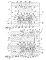
- the actuator 1 is of the double-acting type and comprises: a cylindrical body 2, which is closed at its opposite ends by a respective end plate 3; a piston 4, which is accommodated inside the cylindrical body 2 and can slide axially between the two end plates 3; and a stem 5, which is rigidly associated with the piston 4, is substantially coaxial to the cylindrical body 2 and protrudes from one or both of the end plates 3.
- the stem 5 protrudes from both end plates 3 of the cylindrical body 2; as an alternative, it might also protrude from just one of the two end plates 3.
- the piston 4 separates the cylindrical body 2 into two chambers 6a and 6b, each of which is provided with an opening 7 that is formed proximate to the respective end plate 3 for the inflow and/or outflow of a working fluid.
- the piston 4 comprises at least one pair of one-way valves 8a and 8b, which are arranged inline, are substantially. parallel to the axis A of the cylindrical body 2, and have their respective inlet 9 connected to the respective chamber 6a and 6b and their respective outlets 10 connected to each other.
- Each one of the two valves 8a and 8b is provided with a stem 11, which is accommodated so that it can slide axially within the respective inlet 9 and has an end 11' that is associated with the respective flow control element 12 and an opposite end 11'' that protrudes externally from the piston 4.
- the stem 11 is suitable to open the respective valve 8a and 8b when the piston 4 is located. proximate to the end plate 3 (closed end) of the corresponding chamber 6a and 6b, the other valve 8a and 8b being at least partially opened by the flow of the pressurized working fluid in the other chamber 6a and 6b in order to transfer an amount of fluid from the higher-pressure chamber to the lower-pressure chamber.
- the two valves 8a and 8b are formed by a hole 13, which is formed through the piston 4 with a variable cross-section, its central portion, which has a smaller cross-section, forming the two outlets 10, and by plugs 14, which are snugly accommodated in the open ends of the hole 13 and in which there is a respective guide 15, in which the respective stem 11 is inserted so that it can slide with clearance, and a contact seat 16 for the flow control element 12.
- the guides 15 form the inlets 9; inside said inlets there are means for stopping the sliding of the respective stem 11, which are constituted for example by an annular protrusion 17, which is suitable to act as a stop abutment of a collar 18 formed proximate to the end 11' of the stem 11.
- Elastic contrast means such as for example a spring 19, are interposed between the two flow control elements 12, and are suitable to keep them in contact against the respective contact seat 16.
- valves 8a and 8b are also possible; they might be for example of the mushroom type, or the flow control element 12 and the respective contact seat 16 might have for example a different shape.
- the actuator 1 comprises means 20 for spacing the piston 4 from the end plates 3 (closed ends) of the cylindrical body 2, which are suitable to ensure a nonzero volume of the corresponding chamber 6a and 6b when the piston 4 is located proximate to the end plates 3.
- the spacer means 20 may comprise, for example, a protrusion 21 that protrudes on both opposite faces of the piston 4; however, alternative embodiments of the spacer means 20 are not excluded: for example, the protrusion 21 might be formed on the surfaces of the end plates 3 that face the inside of the chambers 6a and 6b.
- the protruding ends 11'' of the stems 11 are longer than the thickness of the protrusions 21 and/or the stroke of the stems 11 is longer than the thickness of the protrusions 21.
- the piston 4 is provided with gaskets 22 for providing a seal with the internal walls of the cylindrical body 2; the end plates 3 are provided with respective seals 23 with respect to the stem 5, at the opposite ends of which there are couplings 24 for connection to the user devices that they actuate.
- the actuator 1 may be used in particular for hydraulic or mechanical power steering systems for vehicles with at least three steered wheels;
- Figure 1 schematically illustrates a purely hydraulically-actuated steering system G of a vehicle with four steered wheels R in two configurations: with "straight" wheels (solid lines) and steering to the left (in dashed lines).
- the system G substantially comprises two front steered wheels R1 and two rear steered wheels R2, which are associated with a respective fluid-operated actuation mechanism M1 and M2, a tank 25 for the fluid, and a pump 26 for feeding the fluid from the tank 25 to a hydraulic power steering device that is constituted by a power steering unit 27, which is associated with a line 28 for transmitting the fluid to the two actuation mechanisms M1 and M2 and for the return of said fluid to the tank 25.
- a filter 29 is interposed between the pump 26 and the tank 25, while the power steering unit 27 is actuated by a steering column 30 by means of a steering wheel 31.
- Each one of the two actuation mechanisms M1 and M2 is constituted by an actuator 1 according to the present invention, in which the stem 5 has ends that protrude from the end plates 3 and are articulated to respective levers 32 for steering a respective wheel R1 or R2.
- the steering system might have a configuration that is different from the one shown, which should not be considered as limiting the application of the actuator according to invention.
- An essential condition is that the steering system be purely hydraulically-actuated on both front and rear axles; or that it be of the mechanical power-assisted type on one axle and of the hydraulic type on the other axle.
- the steering system might be of the mechanical power-assisted type at the front axle and of the hydraulic type at the rear axle, the actuator of the power-assist system being able to act as a pump for the rear control actuator; the actuator 1 can also be applied to this steering system.
- system G might comprise additional devices, which are not described or shown because they are of a known type, such as for example flow inverters, distribution units that are suitable to select the steering modes (with two or four wheels), or others.
- the two actuation mechanisms M1 and/or M2 also might have a different configuration without this constituting a limitation of the present invention; for example, they could be constituted by an actuator 1 that actuates one wheel of one of the two front and rear pairs, the other wheel of the same pair being actuated by a coupling bar, or they might be constituted by an actuator 1, which also acts as a linking bar.
- the hydraulic power steering unit 27 sends the fluid into the chamber 6b (at a higher pressure) of the actuator 1 that operates the rear wheels R2, pushing the corresponding piston 4 toward the end plate 3 of the corresponding chamber 6a (at a lower pressure).
- the fluid in output from the chamber 6a of the actuator 1 is conveyed by the line 28 so as to feed the chamber 6b (at a higher pressure) of the actuator 1 that actuates the front wheels R1, while the fluid in output from the chamber 6a of this last actuator 1 returns to the tank 25.
- valve 8a remains closed even though the valve 8b is at least partially opened by the pressure applied to the respective flow control element 12 by the pressurized fluid inside the chamber 6b.
- a given amount of fluid bleeds, in a controlled manner, from the chamber 6b (at a higher pressure) to the chamber 6a (at a lower pressure), the valve 8b being at least partially opened by the pressure applied to the respective flow control element 12 by the pressurized fluid inside the chamber 6b.
- This "overfed” amount is sent to the chamber 6b of the actuator 1 that actuates the front wheels R1, of which it therefore takes up any unwanted misalignments with respect to the rear wheels R2 caused by any accidental internal bleeding of the respective actuator 1.
- the actuator 1 is symmetrical; its operation is therefore similar to the operation described above if a right turn is performed instead of a left turn.
- the operation of the actuator 1 can be deduced easily, by the person skilled in the art both in other steering configurations of the system G and if applied to steering systems having a different configuration.
- the actuator according to the invention in fact allows to realign automatically, precisely and constantly the rear and front wheels of a vehicle with four steered wheels with a purely hydraulic or mechanical power steering system, regardless of the skill and sensitivity of the operators and of the particular operating conditions (dimensional tolerances of said cylinder, physical characteristics of the fluid, et cetera), without any electronic control device and without subjecting the gaskets of the corresponding piston to wear, stresses and damage in excess of those that occur during usual operation.
- the actuator according to the invention provides fully automatic realignment of the wheels every time one of the two actuators applied to the two actuation mechanisms of the two pairs of front and rear wheels reaches the end of its stroke, without requiring any control or intervention on the part of operators.
- the wheels are made to assume the theoretical design steering angles, and therefore by realigning the steering wheel they resume a configuration in which they are perfectly aligned with respect to each other.
Landscapes
- Engineering & Computer Science (AREA)
- Chemical & Material Sciences (AREA)
- Combustion & Propulsion (AREA)
- Transportation (AREA)
- Mechanical Engineering (AREA)
- Steering-Linkage Mechanisms And Four-Wheel Steering (AREA)
Applications Claiming Priority (2)
| Application Number | Priority Date | Filing Date | Title |
|---|---|---|---|
| IT000019A ITMO20040019A1 (it) | 2004-01-29 | 2004-01-29 | Attuatore lineare a mezzo fluido per gruppi di sterzo a comando idraulico o meccanico servoassistito di veicoli ad almeno tre ruote sterzanti. |
| ITMO20040019 | 2004-01-29 |
Publications (1)
| Publication Number | Publication Date |
|---|---|
| EP1559634A1 true EP1559634A1 (de) | 2005-08-03 |
Family
ID=34640382
Family Applications (1)
| Application Number | Title | Priority Date | Filing Date |
|---|---|---|---|
| EP05001851A Withdrawn EP1559634A1 (de) | 2004-01-29 | 2005-01-28 | Hydraulisch betriebener Linearaktuator für hydraulisches oder mechanisches Servo-Lenkungssystem von Kraftfahrzeugen mit wenigstens drei lenkbaren Rädern |
Country Status (3)
| Country | Link |
|---|---|
| US (1) | US7168360B2 (de) |
| EP (1) | EP1559634A1 (de) |
| IT (1) | ITMO20040019A1 (de) |
Cited By (2)
| Publication number | Priority date | Publication date | Assignee | Title |
|---|---|---|---|---|
| CN106714546A (zh) * | 2014-05-29 | 2017-05-24 | 马切桑工具及农业机械股份公司 | 用于甘蔗收割机的四个车轮的转向系统 |
| CN111731378A (zh) * | 2020-06-16 | 2020-10-02 | 东风商用车有限公司 | 一种具有行程卸荷阀的转向助力缸总成 |
Families Citing this family (5)
| Publication number | Priority date | Publication date | Assignee | Title |
|---|---|---|---|---|
| US7699674B1 (en) | 2007-09-05 | 2010-04-20 | Brunswick Corporation | Actuator for a marine steering system |
| US9057448B2 (en) * | 2009-08-11 | 2015-06-16 | Safoco, Inc. | Internal relief valve for a valve actuator |
| US9849957B1 (en) | 2015-03-31 | 2017-12-26 | Brunswick Corporation | Systems and steering actuators for steering outboard marine engines |
| US10518858B1 (en) | 2017-07-12 | 2019-12-31 | Brunswick Corporation | Systems and steering actuators for steering outboard marine engines |
| US20220355854A1 (en) * | 2021-05-04 | 2022-11-10 | Ronald Gene Timmons | Self-centering double ended hydraulic steering cylinder that uses no electronics |
Citations (3)
| Publication number | Priority date | Publication date | Assignee | Title |
|---|---|---|---|---|
| US3315570A (en) * | 1965-01-07 | 1967-04-25 | Gen Motors Corp | Pressure relieving means |
| US4006664A (en) * | 1975-04-03 | 1977-02-08 | Pettibone Corporation | Steering system including tandem hydraulic cylinders with self-synchronization |
| EP0321756A2 (de) * | 1987-12-21 | 1989-06-28 | Trw Inc. | Verfahren und Vorrichtung zum Ändern der Einstellung von Überdruck-Tellerventilen |
Family Cites Families (1)
| Publication number | Priority date | Publication date | Assignee | Title |
|---|---|---|---|---|
| US3181429A (en) * | 1963-09-30 | 1965-05-04 | Allis Chalmers Mfg Co | Piston and unloading valve therefor |
-
2004
- 2004-01-29 IT IT000019A patent/ITMO20040019A1/it unknown
-
2005
- 2005-01-28 EP EP05001851A patent/EP1559634A1/de not_active Withdrawn
- 2005-03-23 US US11/086,425 patent/US7168360B2/en not_active Expired - Fee Related
Patent Citations (3)
| Publication number | Priority date | Publication date | Assignee | Title |
|---|---|---|---|---|
| US3315570A (en) * | 1965-01-07 | 1967-04-25 | Gen Motors Corp | Pressure relieving means |
| US4006664A (en) * | 1975-04-03 | 1977-02-08 | Pettibone Corporation | Steering system including tandem hydraulic cylinders with self-synchronization |
| EP0321756A2 (de) * | 1987-12-21 | 1989-06-28 | Trw Inc. | Verfahren und Vorrichtung zum Ändern der Einstellung von Überdruck-Tellerventilen |
Cited By (3)
| Publication number | Priority date | Publication date | Assignee | Title |
|---|---|---|---|---|
| CN106714546A (zh) * | 2014-05-29 | 2017-05-24 | 马切桑工具及农业机械股份公司 | 用于甘蔗收割机的四个车轮的转向系统 |
| CN114132117A (zh) * | 2014-05-29 | 2022-03-04 | 马切桑工具及农业机械股份公司 | 用于甘蔗收割机的四个车轮的转向系统 |
| CN111731378A (zh) * | 2020-06-16 | 2020-10-02 | 东风商用车有限公司 | 一种具有行程卸荷阀的转向助力缸总成 |
Also Published As
| Publication number | Publication date |
|---|---|
| US20050166585A1 (en) | 2005-08-04 |
| ITMO20040019A1 (it) | 2004-04-29 |
| US7168360B2 (en) | 2007-01-30 |
Similar Documents
| Publication | Publication Date | Title |
|---|---|---|
| DE2942980C2 (de) | Blockiergeschützte hydraulische Fahrzeugbremse | |
| EP3099955A1 (de) | Vorrichtung zur hydraulischen betätigung einer kraftfahrzeug-reibkupplung | |
| US7168360B2 (en) | Steering system actuator for vehicle with at least three steered wheels | |
| CA2797706C (en) | Control of a fluid pump assembly | |
| GB2465639A (en) | Fault-tolerant chemical injection system for oil and gas wells | |
| US4355708A (en) | Disc brakes | |
| US8789668B2 (en) | Master cylinder assembly, in particular for balancing a braking system of an agricultural vehicle | |
| RU2446067C2 (ru) | Клапан для отключения переднего тормоза и/или тормоза прицепа для сельскохозяйственного трактора или аналогичного транспортного средства | |
| CA1040024A (en) | Fluid motor construction | |
| US3946563A (en) | Master cylinders for dual hydraulic braking systems | |
| US5018607A (en) | Hydraulic dashpot for pipeline systems | |
| US2830561A (en) | Telemeter type hydraulic power transmitting system | |
| US5125323A (en) | Pressurized oil supply/discharge circuit and valve device for use in such circuit | |
| CA1233091A (en) | Pneumatic valve | |
| EP0505532B1 (de) | Blockiergeschützte bremsanlage | |
| US3314335A (en) | Actuator locking mechanism | |
| EP0668441B1 (de) | Einrichtung zur Antriebssteuerung einer Zweizylinder-Dickstoffpumpe | |
| DE3913351A1 (de) | Vorrichtung zur hilfsdruckerzeugung | |
| US3887160A (en) | Fluid operated actuator for movable members | |
| EP3000672B1 (de) | Anhängerventilanordnung | |
| US4903728A (en) | Safety valve | |
| JPH0242290A (ja) | 安全弁 | |
| EP3204277B1 (de) | Druckausgleichvorrichtung für hydraulische bremssysteme | |
| EP2268935A1 (de) | Vorrichtung zum betätigen einer kupplung | |
| AU625197B2 (en) | Pressure-balanced proportioning valve with vent-controlled bypass |
Legal Events
| Date | Code | Title | Description |
|---|---|---|---|
| PUAI | Public reference made under article 153(3) epc to a published international application that has entered the european phase |
Free format text: ORIGINAL CODE: 0009012 |
|
| AK | Designated contracting states |
Kind code of ref document: A1 Designated state(s): AT BE BG CH CY CZ DE DK EE ES FI FR GB GR HU IE IS IT LI LT LU MC NL PL PT RO SE SI SK TR |
|
| AX | Request for extension of the european patent |
Extension state: AL BA HR LV MK YU |
|
| 17P | Request for examination filed |
Effective date: 20060112 |
|
| AKX | Designation fees paid |
Designated state(s): AT BE BG CH CY CZ DE DK EE ES FI FR GB GR HU IE IS IT LI LT LU MC NL PL PT RO SE SI SK TR |
|
| 17Q | First examination report despatched |
Effective date: 20060821 |
|
| STAA | Information on the status of an ep patent application or granted ep patent |
Free format text: STATUS: THE APPLICATION IS DEEMED TO BE WITHDRAWN |
|
| 18D | Application deemed to be withdrawn |
Effective date: 20080313 |