EP1559619B1 - Device for stepwise height adjustment of vehicle seat belt direction reversal fitting on a hollow chassis component of a vehicle - Google Patents
Device for stepwise height adjustment of vehicle seat belt direction reversal fitting on a hollow chassis component of a vehicle Download PDFInfo
- Publication number
- EP1559619B1 EP1559619B1 EP04025704A EP04025704A EP1559619B1 EP 1559619 B1 EP1559619 B1 EP 1559619B1 EP 04025704 A EP04025704 A EP 04025704A EP 04025704 A EP04025704 A EP 04025704A EP 1559619 B1 EP1559619 B1 EP 1559619B1
- Authority
- EP
- European Patent Office
- Prior art keywords
- guide rail
- vehicle
- body part
- holding
- tab
- Prior art date
- Legal status (The legal status is an assumption and is not a legal conclusion. Google has not performed a legal analysis and makes no representation as to the accuracy of the status listed.)
- Expired - Lifetime
Links
Images

Classifications
-
- B—PERFORMING OPERATIONS; TRANSPORTING
- B60—VEHICLES IN GENERAL
- B60R—VEHICLES, VEHICLE FITTINGS, OR VEHICLE PARTS, NOT OTHERWISE PROVIDED FOR
- B60R21/00—Arrangements or fittings on vehicles for protecting or preventing injuries to occupants or pedestrians in case of accidents or other traffic risks
- B60R21/02—Occupant safety arrangements or fittings, e.g. crash pads
- B60R21/055—Padded or energy-absorbing fittings, e.g. seat belt anchors
-
- B—PERFORMING OPERATIONS; TRANSPORTING
- B60—VEHICLES IN GENERAL
- B60R—VEHICLES, VEHICLE FITTINGS, OR VEHICLE PARTS, NOT OTHERWISE PROVIDED FOR
- B60R22/00—Safety belts or body harnesses in vehicles
- B60R22/18—Anchoring devices
- B60R22/20—Anchoring devices adjustable in position, e.g. in height
- B60R22/201—Anchoring devices adjustable in position, e.g. in height with the belt anchor connected to a slider movable in a vehicle-mounted track
Definitions
- the present invention relates to a device for the stepwise height adjustment of a retaining or deflecting fitting of a safety belt on a hollow body part of a motor vehicle, in particular on a B or C-pillar, with a mounted on the body part guide rail, a displaceable along the guide rail and fixable in defined adjustment positions
- the belt height adjustment devices serve to adjust the height of the deflection or attachment point of a seat belt to the height of a vehicle occupant to be secured.
- the belt height adjustment devices are usually mounted in the upper part of the B and C pillars.
- To adjust the height of the fitting of the carriage is usually pressed by pressure on a cap of the holding or deflection fitting with the carriage connecting screw against the force of a spring in the direction of the column, caused by mutual latching engagement of locking elements of the carriage and the guide rail Release fixation so that the carriage can be moved along the guide rail in the desired adjustment position.
- the locking elements occur again in mutual latching engagement, so that the carriage is held in the selected adjustment position.
- US 2002/060452 A1 is a device for the stepwise height adjustment of a retaining or deflection fitting of a safety belt on a hollow body part of a motor vehicle, in particular on a B or C-pillar, with a mounted on the body part guide rail, a slidable along the guide rail and carriage which can be fixed in defined adjustment positions and has a fastening device for the retaining or deflecting fitting, wherein the guide rail arranged behind a pillar trim can be attached to the body part via two fastenings extending at a distance from one another.
- a deformation element is interposed between a carrier plate receiving the guide rail and a column wall.
- Such a device is also known from DE-196 30 498.
- a device for a belt height adjuster wherein the device for energy absorption in a head impact between a guide rail and / or a support plate and a side wall of the column has deformation elements in the form of conically shaped deformation elements.
- the object of the invention is to develop an attachment for a generic Gurteuxnverstellvorraum so that in the event of a head impact on the holding or deflection fitting acting on the head of the vehicle occupant loads below the allowable limit.
- the Gurt bannverstellvoretti pivots about the upper attachment and seen from the passenger compartment, against the direction of travel to the rear.
- the Gurt Ecknverstellvorraum thus deviates laterally in the longitudinal direction of the vehicle with energy absorption.
- the energy absorption is formed by an angled column-side tab, which bends or deforms during pivoting of the guide rail of the belt height adjustment device.
- the geometry of the flap (length, width, thickness, angle of attack) can be used to define the force level at which the flap bends when the guide rail is swiveled.
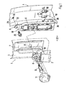
- the belt height adjustment device 1 illustrated in the drawing for a safety belt 2 of a passenger car essentially consists of a guide rail 5 mounted behind a pillar trim 3 on a pillar 4 of the passenger car, a carriage 6 displaceable along the guide rail 5 and fixable in defined adjustment positions on the guide rail 5 , a slider 7 mounted in front of the guide rail 5 over a recess of the pillar trim 3 with a through opening 8, a holding or deflecting fitting 9 with a guide slot 10 for the seat belt 2, and a through-opening 8 of the slider 7, covered with a cap 11 Retaining screw 12 for attaching the retaining or deflection fitting 9 on the carriage. 6
- FIG. 2 there is serving as a holder for the guide rail 5, simplified trapezoidal cross-section shown portion of the B or C-pillar 4 of a channel-shaped outer panel 13, a hat-shaped profiled inner panel 14 and a fixed to the inner panel 14 inner reinforcing plate 15.
- the outer panel 13 and the inner panel 14 are connected to rectified end flanges 16, 17 by welding, gluing or the like. With each other.
- the column 4 forms in the embodiment, the hollow body part.
- the arranged behind the pillar trim 3 profiled guide rail 5 of the Gurt einnverstellvorraum 1 can be attached to the column 4 via two seen in the height direction with spaced-apart fasteners 18, 19 attached.
- the guide rail 5 and thus the entire Gurt Whynverstellvortechnisch 1 with energy absorption to one of the two fasteners 18, 19 of the guide rail 5, extending in the vehicle transverse direction Rotation axis 20 is laterally pivotable.
- the guide rail 5 is held at its upper end 21 via a fastening 18 forming screw fastening to the column 4 in position, wherein the screw fastening forms the stationary axis of rotation 20 during pivoting of the guide rail 5.
- the screw fastening has on the passenger compartment 22 facing region of the inner panel 14 and the reinforcing plate 15 each aligned through holes 23, wherein on a cavity-side surface of the reinforcing plate 15, a nut 24 for serving for fixing the guide rail 5 screw 25 is welded (Fig ).
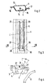
- the guide rail acts at its lower end 26 via at least one attachment 19 forming plug connection with the column 4 together.
- the connector 19 comprises on the column 4 a pair of spaced vertical longitudinal slots 27 through which a respective hook-shaped retaining tongue 28 of the guide rail 5 can be inserted in order to support the guide rail 5 on the column 4 before it is fastened with the screw 25 ,
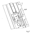
- the longitudinal slots 27 have - seen in the vehicle longitudinal direction - a substantially greater width B1, as the thickness B2 of the retaining tongue 28 (Fig. 7).
- a projecting angled tab 30 is formed, the free end is supported on the adjacent side wall 31 of the retaining tongue 28 of the guide rail 5, wherein in a head-impact-induced pivotal movement of the guide rail 5, the tab 30 under energy absorption, that is, by deformation work, bends or deformed.
- Formed tab 30 is disposed in the embodiment of an inner reinforcing plate 15 of the column 4. However, it could also be provided on the inner panel 14 of the column 4.
- the tab 30 In the installed position C of the guide rail 5, the tab 30 extends and an angle ⁇ of about 45 ° to the adjacent side wall 31 of the retaining tongue 28.
- the angle ⁇ is in the exemplary embodiment about 45 °; However, it can also be less than or greater than 45 °.
- the tab 30 is directed inwardly into the cavity of the column 4 ( Figures 2 and 4). When pivoting the guide rail 5 in its end position D, the tab 30 is bent in the direction of arrow R and extends approximately parallel to the side wall 31 of the retaining tongue 28 (Fig. 6).
- the head K of a vehicle occupant When driving, the head K of a vehicle occupant extends at a distance from the retaining or deflecting fitting 9 of the belt height adjustment device 1 (FIG. 4).
- the head K of the vehicle occupant can move sideways in the direction of the belt height adjustment device 1 and then comes into contact with the pillar trim 3 or the retaining or deflecting fitting 9 (FIG. 6).
- the inventive fastening of the guide rail 5 of the Gurt Jardinnverstellvorides 1 to the column 4 is achieved that 5 energy is absorbed at the head impact first by deformation of the pillar trim 3 and then by deformation work during pivoting of the guide rail, so that the allowable limits for the Kopfetzschlag are reliably exceeded ,
- the guide rail 5 pivots at the head impact about the upper extending in the vehicle transverse direction of rotation axis 20 in the longitudinal direction of the vehicle and in the direction A against the direction of travel F of the vehicle.
Landscapes
- Engineering & Computer Science (AREA)
- Mechanical Engineering (AREA)
- Automotive Seat Belt Assembly (AREA)
Description
Die vorliegende Erfindung betrifft eine Vorrichtung zur stufenweisen Höhenverstellung eines Halte- oder Umlenkbeschlages eines Sicherheitsgurtes an einem hohlen Karosserieteil eines Kraftfahrzeugs, insbesondere an einer B- oder C-Säule, mit einer am Karosserieteil angebrachten Führungsschiene, einem entlang der Führungsschiene verschiebbaren und in definierten Verstellpositionen fixierbaren Schlitten mit einer Befestigungseinrichtung für den Halte- oder Umlenkbeschlag, wobei die hinter einer Säulenverkleidung angeordnete Führungsschiene über zwei mit Abstand zueinander verlaufende Befestigungen am Karosserieteil anbringbar ist.The present invention relates to a device for the stepwise height adjustment of a retaining or deflecting fitting of a safety belt on a hollow body part of a motor vehicle, in particular on a B or C-pillar, with a mounted on the body part guide rail, a displaceable along the guide rail and fixable in defined adjustment positions Carriage with a fastening device for the holding or deflection fitting, wherein the guide rail arranged behind a pillar trim can be attached via two mutually spaced fastenings on the body part.
Vorrichtungen der eingangs genannten Art, die in der Regel als Gurthöhenverstellvorrichtung bezeichnet werden, dienen zur Anpassung der Höhe des Umlenk- oder Befestigungspunktes eines Sicherheitsgurts an die Körpergröße eines zu sichernden Fahrzeuginsassen. Bei viertürigen Personenkraftwagen sind die Gurthöhenverstellvorrichtungen gewöhnlich im oberen Teil der B- und C-Säule angebracht. Zum Verstellen der Höhe des Beschlags wird der Schlitten zumeist durch Druck auf eine Abdeckkappe einer den Halte- oder Umlenkbeschlag mit dem Schlitten verbindenden Schraube entgegen der Kraft einer Feder in Richtung der Säule gedrückt, um die durch gegenseitigen Rasteingriff von Rastelementen des Schlittens und der Führungsschiene bewirkte Fixierung zu lösen, damit sich der Schlitten entlang der Führungsschiene in die gewünschte Verstellposition bewegen lässt. Bei einer anschließenden Druckentlastung der Abdeckkappe treten die Rastelemente erneut in gegenseitigen Rasteingriff, so dass der Schlitten in der gewählten Verstellposition festgehalten wird.Devices of the type mentioned, which are usually referred to as Gurthöhenverstellvorrichtung serve to adjust the height of the deflection or attachment point of a seat belt to the height of a vehicle occupant to be secured. In four-door passenger cars, the belt height adjustment devices are usually mounted in the upper part of the B and C pillars. To adjust the height of the fitting of the carriage is usually pressed by pressure on a cap of the holding or deflection fitting with the carriage connecting screw against the force of a spring in the direction of the column, caused by mutual latching engagement of locking elements of the carriage and the guide rail Release fixation so that the carriage can be moved along the guide rail in the desired adjustment position. In a subsequent pressure relief of the cap, the locking elements occur again in mutual latching engagement, so that the carriage is held in the selected adjustment position.
Derartige Vorrichtungen sind im Stand der Technik vielfach bekannt; beispielsweise wird auf die DE 198 22 696 A1 hingewiesen.Such devices are widely known in the art; For example, reference is made to DE 198 22 696 A1.
Sofern im Falle eines Unfalles eines damit ausgerüsteten Fahrzeuges beispielsweise seitliche Kräfte auf das Fahrzeug einwirken, besteht die Gefahr, dass der Kopf eines Kraftfahrzeuginsassen eine Querbewegung ausführt und auf den Bereich aufprallt, in dem der Umlenkbeschlag angeordnet ist. Hierbei können auf den Kopf des Kraftfahrzeuginsassen Belastungen einwirken, die oberhalb des zulässigen Grenzwertes liegen.If, for example, lateral forces act on the vehicle in the event of an accident of a vehicle equipped with it, there is a risk that the head of a motor vehicle occupant will make a transverse movement and impact the area in which the deflection fitting is arranged. This can affect the head of the vehicle occupant loads that are above the allowable limit.
Aus der DE 197 19 572 A1 ist es bekannt, zwischen dem Sicherheitsgurt-Anlenkpunkt und dem Karosserieteil ein zur Energieabsorption bei einer Druckbeaufschlagung auf den Sicherheitsgurt-Anlenkpunkt ausgelegtes Deformationselement anzuordnen. Ein derartiges Deformationselement beansprucht in Fahrzeugquerrichtung gesehen einen relativ großen zusätzlichen Bauraum.From DE 197 19 572 A1 it is known to arrange between the seat belt pivot point and the body part designed for energy absorption at a pressurization on the seat belt pivot point deformation element. Such a deformation element claimed in the vehicle transverse direction seen a relatively large additional space.
Aus der DE 196 15 804 C2 ist es bekannt, im Zwischenraum zwischen dem den Umlenkbeschlag haltenden Verstellteil und dem Karosserieteil, an welchem die Schiene befestigt oder befestigbar ist, ein Dämpfungsmittel anzuordnen, welches sich bei auf den Umlenkbeschlag einwirkenden aufprallbedingten Kräften am Verstellteil und Karosserieteil abstützt und hierbei zur Dämpfung der Aufprallenergie deformierbar ist. Zur Unterbringung eines derartigen Dämpfungsmittels ist ein entsprechender Bauraum vorzusehen.From DE 196 15 804 C2 it is known to arrange a damping means in the space between the Verstellbeschlag holding adjusting part and the body part, to which the rail is attached or fastened, which is supported when acting on the deflection fitting impact-related forces on the adjustment and body part and in this case is deformable for damping the impact energy. To accommodate such a damping means a corresponding space is provided.
Aus der gattungsbildenden US 2002/060452 A1 geht eine Vorrichtung zur stufenweisen Höhenverstellung eines Halte- oder Umlenkbeschlags eines Sicherheitsgurts an einem hohlen Karosserieteil eines Kraftfahrzeugs, insbesondere an einer B- oder C-Säule, mit einer am Karosserieteil angebrachten Führungsschiene, einem entlang der Führungsschiene verschiebbaren und in definierten Verstellpositionen fixierbaren Schlitten mit einer Befestigungseinrichtung für den Halte- oder Umlenkbeschlag hervor, wobei die hinter einer Säulenverkleidung angeordnete Führungsschiene über zwei mit Abstand zueinander verlaufende Befestigungen am Karosserieteil anbringbar ist.From the generic US 2002/060452 A1 is a device for the stepwise height adjustment of a retaining or deflection fitting of a safety belt on a hollow body part of a motor vehicle, in particular on a B or C-pillar, with a mounted on the body part guide rail, a slidable along the guide rail and carriage which can be fixed in defined adjustment positions and has a fastening device for the retaining or deflecting fitting, wherein the guide rail arranged behind a pillar trim can be attached to the body part via two fastenings extending at a distance from one another.
Bei einem Kopfschlag eines Fahrzeuginsassen auf den Halte- oder Umlenkbeschlag ist ab einem definierten Kraftniveau die Führungsschiene und somit die gesamte Gurthöhenverstellvorrichtung unter Energieabsorption um eine durch die obere Befestigung der Führungsschiene gebildete Drehachse verschwenkbar und zwar in Fahrzeugquerrichtung. Bei dieser Anordnung ist zwischen einer die Führungsschiene aufnehmenden Trägerplatte und einer Säulenwand ein Deformationselement zwischengeschalten.In a head beat of a vehicle occupant on the holding or deflection fitting is from a defined level of force, the guide rail and thus the entire Gurthöhenverstellvorrichtung under energy absorption about an axis formed by the upper mounting of the guide rail pivot axis and indeed in the vehicle transverse direction. In this arrangement, a deformation element is interposed between a carrier plate receiving the guide rail and a column wall.
Eine derartige Vorrichtung ist auch aus DE-196 30 498 bekannt.Such a device is also known from DE-196 30 498.
Aus der EP 1 132 264 A2 ist eine Vorrichtung für einen Gurthöhenversteller bekannt, wobei die Vorrichtung zur Energieabsorption bei einem Kopfaufprall zwischen einer Führungsschiene und/oder einer Trägerplatte und einer Seitenwand der Säule Deformationselemente in Form von kegelförmig ausgebildeten Deformationselementen aufweist.From EP 1 132 264 A2, a device for a belt height adjuster is known, wherein the device for energy absorption in a head impact between a guide rail and / or a support plate and a side wall of the column has deformation elements in the form of conically shaped deformation elements.
Aufgabe der Erfindung ist es, eine Befestigung für eine gattungsgemäße Gurthöhenverstellvorrichtung so weiterzubilden, dass im Falle eines Kopfaufpralles auf den Halte- oder Umlenkbeschlag die auf den Kopf des Fahrzeuginsassen einwirkenden Belastungen unterhalb des zulässigen Grenzwertes liegen.The object of the invention is to develop an attachment for a generic Gurthöhenverstellvorrichtung so that in the event of a head impact on the holding or deflection fitting acting on the head of the vehicle occupant loads below the allowable limit.
Erfindungsgemäß wird diese Aufgabe durch die Merkmale des Anspruchs 1 gelöst. Weitere die Erfindung in vorteilhafter Weise ausgestaltende Merkmale enthalten die Unteransprüche.According to the invention, this object is solved by the features of claim 1. More embodying the invention in an advantageous manner features include the dependent claims.
Die mit der Erfindung hauptsächlich erzielten Vorteile sind darin zu sehen, dass bei einem Kopfaufschlag auf den Halte- oder Umlenkbeschlag bei einem definierten Kraftniveau die Gurthöhenverstellvorrichtung unter Energieabsorption um eine durch eine der beiden Befestigungen der Trägerschiene gebildete, in Fahrzeugquerrichtung verlaufende Drehachse seitlich verschwenkbar ist, wobei beim Verschwenken der Gurthöhenverstellvorrichtung Energie absorbiert wird und somit die auftretenden Kopfbelastungen unterhalb des zulässigen Grenzwertes liegen. Eine zusätzliche Energieabsorption kann darüber hinaus durch Verformung der vorgelagerten Säulenverkleidung erfolgen.The advantages achieved by the invention can be seen in the fact that in a head impact on the holding or deflection fitting at a defined level of force Gurthöhenverstellvorrichtung is under energy absorption about a formed by one of the two fasteners of the support rail, extending in the vehicle transverse direction of rotation axis laterally, wherein energy is absorbed during pivoting of the belt height adjustment device and thus the occurring head loads are below the permissible limit value. In addition, additional energy absorption can be achieved by deformation of the upstream pillar trim.
Im Ausführungsbeispiel schwenkt die Gurthöhenverstellvorrichtung um die obere Befestigung und zwar vom Fahrgastraum aus gesehen entgegen der Fahrtrichtung nach hinten. Die Gurthöhenverstellvorrichtung weicht also unter Energieabsorption seitlich in Längsrichtung des Fahrzeuges aus. Die Energieabsorption wird durch eine abgewinkelte säulenseitige Lasche gebildet, die sich beim Verschwenken der Führungsschiene der Gurthöhenverstellvorrichtung verbiegt bzw. verformt. Durch die Geometrie der Lasche (Länge, Breite, Dicke, Anstellwinkel) lässt sich das Kraftniveau festlegen, ab dem sich die Lasche beim Verschwenken der Führungsschiene verbiegt.In the exemplary embodiment, the Gurthöhenverstellvorrichtung pivots about the upper attachment and seen from the passenger compartment, against the direction of travel to the rear. The Gurthöhenverstellvorrichtung thus deviates laterally in the longitudinal direction of the vehicle with energy absorption. The energy absorption is formed by an angled column-side tab, which bends or deforms during pivoting of the guide rail of the belt height adjustment device. The geometry of the flap (length, width, thickness, angle of attack) can be used to define the force level at which the flap bends when the guide rail is swiveled.
Im Folgenden wird die Erfindung anhand eines in der Zeichnung dargestellten Ausführungsbeispiels näher erläutert.
Es zeigen
- Fig. 1
- eine auseinandergezogene perspektivische Ansicht einer erfindungsgemäßen an einer Säule angebrachten Gurthöhenverstellvorrichtung,
- Fig. 2
- einen Schnitt nach der Linie II-II der Fig. 1 in größerer Darstellung durch die Säule,
- Fig. 3
- eine perspektivische Ansicht auf die Türsäule mit der Führungsschiene in Einbaustellung,
- Fig. 4
- einen Schnitt nach der Linie IV-IV der Fig. 3,
- Fig. 5
- eine Ansicht ähnlich Fig. 3, jedoch mit verschwenkter Führungsschiene nach einem Kopfaufprall,
- Fig. 6
- einen Schnitt nach der Linie VI-VI der Fig. 5,
- Fig. 7
- eine Ansicht von innen auf die Türsäule, wobei die Lage der Haltezungen in beiden Endstellungen dargestellt ist.
Show it
- Fig. 1
- an exploded perspective view of a column-mounted on a belt height adjustment device according to the invention,
- Fig. 2
- a section along the line II-II of Figure 1 in a larger view through the column,
- Fig. 3
- a perspective view of the door pillar with the guide rail in the installed position,
- Fig. 4
- a section along the line IV-IV of Fig. 3,
- Fig. 5
- a view similar to FIG. 3, but with swiveled guide rail after a head impact,
- Fig. 6
- a section along the line VI-VI of Fig. 5,
- Fig. 7
- a view from the inside on the door pillar, wherein the position of the retaining tongues is shown in both end positions.
Die in der Zeichnung dargestellte Gurthöhenverstellvorrichtung 1 für einen Sicherheitsgurt 2 eines Personenkraftwagens besteht im Wesentlichen aus einer hinter einer Säulenverkleidung 3 an einer Säule 4 des Personenkraftwagens montierten Führungsschiene 5, einem an der Führungsschiene 5 entlang verschiebbaren und in definierten Verstellpositionen auf der Führungsschiene 5 fixierbaren Schlitten 6, einem vor der Führungsschiene 5 über einer Aussparung der Säulenverkleidung 3 angebrachten Schieber 7 mit einer Durchgangsöffnung 8, einem Halte- oder Umlenkbeschlag 9 mit einem Führungsschlitz 10 für den Sicherheitsgurt 2, sowie einer die Durchgangsöffnung 8 des Schiebers 7 durchsetzenden, mit einer Abdeckkappe 11 verkleideten Halteschraube 12 zum Befestigen des Halte- oder Umlenkbeschlages 9 am Schlitten 6.The belt height adjustment device 1 illustrated in the drawing for a
Wie in Fig. 2 dargestellt, besteht das als Halterung für die Führungsschiene 5 dienende, im Querschnitt vereinfacht trapezförmig dargestellte Teilstück der B- oder C-Säule 4 aus einem rinnenförmigen Außenblech 13, einem hutförmig profilierten Innenblech 14 und einem am Innenblech 14 befestigten inneren Verstärkungsblech 15. Das Außenblech 13 und das Innenblech 14 sind an gleichgerichteten endseitigen Flanschen 16, 17 durch Schweißen, Kleben oder dgl. miteinander verbunden. Auf die Flansche 16, 17 sind nicht näher dargestellte Dichtprofile aufgesteckt. Die Säule 4 bildet im Ausführungsbeispiel das hohle Karosserieteil.As shown in Fig. 2, there is serving as a holder for the
Die hinter der Säulenverkleidung 3 angeordnete profilierte Führungsschiene 5 der Gurthöhenverstellvorrichtung 1 ist über zwei in Höhenrichtung gesehen mit Abstand zueinander verlaufende Befestigungen 18, 19 an der Säule 4 anbringbar.The arranged behind the
Erfindungsgemäß ist vorgesehen, dass bei einem Kopfaufschlag eines Fahrzeuginsassen auf den Halte- oder Umlenkbeschlag 9 ab einem definierten Kraftniveau die Führungsschiene 5 und somit die gesamte Gurthöhenverstellvorrichtung 1 unter Energieabsorption um eine durch eine der beiden Befestigungen 18, 19 der Führungsschiene 5 gebildete, in Fahrzeugquerrichtung verlaufende Drehachse 20 seitlich verschwenkbar ist. Im Ausführungsbeispiel ist die Führungsschiene 5 an ihrem oberen Ende 21 über eine die Befestigung 18 bildende Schraubbefestigung an der Säule 4 in Lage gehalten, wobei die Schraubbefestigung die ortsfeste Drehachse 20 beim Verschwenken der Führungsschiene 5 bildet. Die Schraubbefestigung weist auf dem einem Fahrgastraum 22 zugewandten Bereich des Innenblechs 14 und des Verstärkungsblechs 15 jeweils fluchtende Durchgangsbohrungen 23 auf, wobei auf einer hohlraumseitigen Oberfläche des Verstärkungsblechs 15 eine Schraubenmutter 24 für eine zur Befestigung der Führungsschiene 5 dienende Schraube 25 aufgeschweißt ist (Fig. 1).According to the invention it is provided that in a head impact of a vehicle occupant on the holding or deflection fitting 9 from a defined level of force, the
Die Führungsschiene wirkt an ihrem unteren Ende 26 über zumindest eine die Befestigung 19 bildende Steckverbindung mit der Säule 4 zusammen. Die Steckverbindung 19 umfasst an der Säule 4 ein Paar von im Abstand angeordneten vertikalen Längsschlitzen 27, durch die sich jeweils eine hakenförmige Haltezunge 28 der Führungsschiene 5 einführen lässt, um die Führungsschiene 5 an der Säule 4 abzustützen, bevor sie mit der Schraube 25 befestigt wird.The guide rail acts at its
Die Längsschlitze 27 weisen - in Fahrzeuglängsrichtung gesehen - eine wesentlich größere Breite B1 auf, als die Dicke B2 der Haltezunge 28 (Fig. 7). Wenigstens an einer aufrechten Längsseite 29 eines der beiden Längsschlitze 27 der Säule 4 ist eine vorstehende abgewinkelte Lasche 30 ausgebildet, deren freies Ende sich an der angrenzenden Seitenwand 31 der Haltezunge 28 der Führungsschiene 5 abstützt, wobei sich bei einer kopfaufprallbedingten Schwenkbewegung der Führungsschiene 5 die Lasche 30 unter Energieabsorption, das heißt durch Verformungsarbeit, verbiegt bzw. verformt.The
Die trapezförmig, halbkreisförmig oder dgl. ausgebildete Lasche 30 ist im Ausführungsbeispiel an einem inneren Verstärkungsblech 15 der Säule 4 angeordnet. Sie könnte jedoch auch am Innenblech 14 der Säule 4 vorgesehen sein. In der Einbaustellung C der Führungsschiene 5 verläuft die Lasche 30 und einem Winkel α von etwa 45° zu der angrenzenden Seitenwand 31 der Haltezunge 28. Der Winkel α beträgt im Ausführungsbeispiel etwa 45°; er kann jedoch auch kleiner oder größer als 45° sein. Die Lasche 30 ist nach innen in den Hohlraum der Säule 4 gerichtet (Fig. 2 und 4). Beim Verschwenken der Führungsschiene 5 in ihre Endlage D wird die Lasche 30 in Pfeilrichtung R gebogen und verläuft etwa parallel zur Seitenwand 31 der Haltezunge 28 (Fig. 6).The trapezoidal, semicircular or the like.
Im Fahrbetrieb verläuft der Kopf K eines Fahrzeuginsassen mit Abstand zum Halte- oder Umlenkbeschlag 9 der Gurthöhenverstellvorrichtung 1 (Fig. 4).When driving, the head K of a vehicle occupant extends at a distance from the retaining or deflecting fitting 9 of the belt height adjustment device 1 (FIG. 4).
Bei einer Fahrzeugkollision, insbesondere kann sich der Kopf K des Fahrzeuginsassen zur Seite hin in Richtung der Gurthöhenverstellvorrichtung 1 bewegen und gelangt dann in Kontakt mit der Säulenverkleidung 3 bzw. dem Halte- oder Umlenkbeschlag 9 (Fig. 6). Durch die erfindungsgemäße Befestigung der Führungsschiene 5 der Gurthöhenverstellvorrichtung 1 an der Säule 4 wird erreicht, dass beim Kopfaufschlag zuerst durch Verformung der Säulenverkleidung 3 und danach durch Verformungsarbeit beim Verschwenken der Führungsschiene 5 Energie absorbiert wird, so dass die zulässigen Grenzwerte für den Kopfaufschlag zuverlässig unterschritten werden. Die Führungsschiene 5 schwenkt beim Kopfaufschlag um die obere in Fahrzeugquerrichtung verlaufende Drehachse 20 in Längsrichtung des Fahrzeuges und zwar in Richtung A entgegen der Fahrtrichtung F des Fahrzeuges.In the event of a vehicle collision, in particular, the head K of the vehicle occupant can move sideways in the direction of the belt height adjustment device 1 and then comes into contact with the pillar trim 3 or the retaining or deflecting fitting 9 (FIG. 6). The inventive fastening of the
Claims (6)
- A device for the stepwise height adjustment of a holding or deflection fitting (19) [sic - recte 9] of a safety belt (2) on a hollow body part (4) of a motor vehicle, especially on a B or C pillar, with a guide rail (5) mounted on the body part (4), a slide (6) which is displaceable along the guide rail and is fixable in defined adjustment positions and has a fastening device (12) for the holding or deflection fitting (9), wherein the guide rail (5), which is arranged behind a pillar lining (3), is mountable on the body part (4) by means of two fastenings (18, 19) which extend with mutual spacing and, starting from a defined force level, the guide rail (5) and therefore the entire belt-height adjusting device is laterally pivotable about a rotation axis (20), formed by the upper fastening of the guide rail, with absorption of energy if a vehicle occupant's head strikes the holding or deflection fitting (9), characterised in that the rotation axis (20) extends in the vehicle transverse direction and in that the guide rail (5) is laterally pivotable in the longitudinal direction of the vehicle if it is struck by a vehicle occupant's head.
- A device according to claim 1, characterised in that the guide rail (5) co-operates at its lower end (26) with the body part (4) via at least one plug-in connection (19).
- A device according to claim 2, characterised in that the plug-in connection (19) on the body part (4) comprises a pair of spaced, vertical, longitudinal slots (27), through which a respective hook-shaped holding tongue (28) of the guide rail (5) can be inserted, wherein the longitudinal slots (27), seen in the vehicle longitudinal direction, have a substantially greater width (B1) than the thickness (B2) of the holding tongue (28).
- A device according to any one of the preceding claims, characterised in that a projecting, bent tab (30) is provided on at least one upright longitudinal side (29) of a longitudinal slot (27) and its free end co-operates with an adjacent side wall (31) of the holding tongue (28), wherein the tab (30) deforms with absorption of energy in the event of a pivoting movement of the guide rail (5) about the rotation axis (20).
- A device according to claim 4, characterised in that the tab (30) is formed on an inner reinforcing plate (15) and / or on the inner panel (14) of the body part (4).
- A device according to any one of the preceding claims, characterised in that the tab (30) extends at an angle (α) to the side wall (31) of the holding tongue (28) in the mounted position of the guide rail (5).
Applications Claiming Priority (2)
| Application Number | Priority Date | Filing Date | Title |
|---|---|---|---|
| DE102004003966 | 2004-01-27 | ||
| DE102004003966A DE102004003966B3 (en) | 2004-01-27 | 2004-01-27 | Height adjustment device for passenger seatbelt fixing loop has sliding carriage displaced along guide rail which pivots sidewards upon impact of passenger's head for absorbing impact energy |
Publications (2)
| Publication Number | Publication Date |
|---|---|
| EP1559619A1 EP1559619A1 (en) | 2005-08-03 |
| EP1559619B1 true EP1559619B1 (en) | 2007-05-30 |
Family
ID=34609621
Family Applications (1)
| Application Number | Title | Priority Date | Filing Date |
|---|---|---|---|
| EP04025704A Expired - Lifetime EP1559619B1 (en) | 2004-01-27 | 2004-10-29 | Device for stepwise height adjustment of vehicle seat belt direction reversal fitting on a hollow chassis component of a vehicle |
Country Status (4)
| Country | Link |
|---|---|
| US (1) | US7404579B2 (en) |
| EP (1) | EP1559619B1 (en) |
| DE (2) | DE102004003966B3 (en) |
| ES (1) | ES2285335T3 (en) |
Families Citing this family (8)
| Publication number | Priority date | Publication date | Assignee | Title |
|---|---|---|---|---|
| JP5217035B2 (en) * | 2007-01-11 | 2013-06-19 | オートリブ ディベロップメント エービー | Shoulder adjuster |
| DE102011014175B4 (en) * | 2011-03-16 | 2021-05-12 | Autoliv Development Ab | Height adjuster for a fastening fitting of a seat belt system |
| US20130127230A1 (en) * | 2011-11-21 | 2013-05-23 | Anthony Fini | Vehicle shoulder belt extension |
| EP2962906B1 (en) * | 2014-07-03 | 2016-09-21 | TRW Automotive GmbH | Pressure unit and end fitting with such a pressure unit |
| US9499121B2 (en) * | 2014-11-17 | 2016-11-22 | Indiana Mills & Manufacutring, Inc. | Web position adjustment and attenuation apparatus |
| US9776590B1 (en) * | 2016-06-07 | 2017-10-03 | Nathan Foser | Personal protection assembly |
| DE102016015234B4 (en) | 2016-12-21 | 2021-07-29 | Audi Ag | Motor vehicle with a seat belt system |
| DE202017106964U1 (en) * | 2017-11-16 | 2019-02-20 | Sodecia Automotive Europe Gmbh | Guide rail for a belt height adjuster |
Citations (1)
| Publication number | Priority date | Publication date | Assignee | Title |
|---|---|---|---|---|
| DE19630498A1 (en) * | 1996-07-29 | 1998-02-05 | Autoliv Dev | Vehicle seat belt height adjustment |
Family Cites Families (20)
| Publication number | Priority date | Publication date | Assignee | Title |
|---|---|---|---|---|
| JPS6215064U (en) * | 1985-07-12 | 1987-01-29 | ||
| JPH0537724Y2 (en) * | 1986-07-09 | 1993-09-24 | ||
| JPS63137054U (en) * | 1987-02-27 | 1988-09-08 | ||
| US4878692A (en) * | 1987-07-27 | 1989-11-07 | Kabushiki Kaisha Tokai-Rika-Denki-Seisakusho | Guide rail supporting structure |
| JPH0738025Y2 (en) * | 1987-11-06 | 1995-08-30 | 日本精工株式会社 | Adjustable shoulder anchor mechanism |
| DE3840390A1 (en) * | 1987-12-02 | 1989-06-15 | Nippon Seiko Kk | Passive seat belt system |
| JPH01126863U (en) * | 1988-02-24 | 1989-08-30 | ||
| JPH0290171U (en) * | 1988-12-28 | 1990-07-17 | ||
| JPH038045U (en) * | 1989-06-12 | 1991-01-25 | ||
| JPH04283149A (en) * | 1991-03-08 | 1992-10-08 | Takata Kk | Shoulder adjuster |
| US5232245A (en) * | 1991-11-19 | 1993-08-03 | Trw Vehicle Safety Systems Inc. | Spring clip for passive seat belt system |
| DE19615804C2 (en) * | 1996-04-20 | 1998-12-17 | Schmidt Gmbh R | Device for adjusting the height of a deflection fitting for seat belts |
| DE19719572A1 (en) * | 1996-05-18 | 1997-11-20 | Volkswagen Ag | Fastening device for safety belt link point on car-body |
| DE29713642U1 (en) * | 1997-07-31 | 1997-10-02 | Griesemer, Albert, 56457 Westerburg | Height adjuster for deflection fittings of vehicle seat belts |
| DE19745016C2 (en) * | 1997-10-11 | 2000-07-13 | Porsche Ag | Deflection fitting for seat belts of vehicles, in particular motor vehicles |
| DE19822696A1 (en) * | 1998-05-20 | 1999-11-25 | Volkswagen Ag | Belt height adjustment device with sound damping for vehicle safety belt |
| DE29912874U1 (en) * | 1999-07-23 | 1999-12-09 | TRW Occupant Restraint Systems GmbH & Co. KG, 73553 Alfdorf | Height adjuster for vehicle seat belt |
| DE10011908C1 (en) * | 2000-03-11 | 2001-03-15 | Porsche Ag | Belt height adjustment device for automobile seatbelt has deformation element at rear of ratchet rail and releasable fixing plate for absorption of head impact energy |
| DE10011902C1 (en) * | 2000-03-11 | 2001-08-09 | Porsche Ag | Device for a belt height adjuster of a seat belt system |
| JP4779252B2 (en) * | 2001-07-06 | 2011-09-28 | タカタ株式会社 | Air belt device tongs |
-
2004
- 2004-01-27 DE DE102004003966A patent/DE102004003966B3/en not_active Expired - Fee Related
- 2004-10-29 DE DE502004003938T patent/DE502004003938D1/en not_active Expired - Lifetime
- 2004-10-29 ES ES04025704T patent/ES2285335T3/en not_active Expired - Lifetime
- 2004-10-29 EP EP04025704A patent/EP1559619B1/en not_active Expired - Lifetime
-
2005
- 2005-01-26 US US11/041,939 patent/US7404579B2/en not_active Expired - Lifetime
Patent Citations (1)
| Publication number | Priority date | Publication date | Assignee | Title |
|---|---|---|---|---|
| DE19630498A1 (en) * | 1996-07-29 | 1998-02-05 | Autoliv Dev | Vehicle seat belt height adjustment |
Also Published As
| Publication number | Publication date |
|---|---|
| US20050189758A1 (en) | 2005-09-01 |
| DE102004003966B3 (en) | 2005-06-23 |
| ES2285335T3 (en) | 2007-11-16 |
| DE502004003938D1 (en) | 2007-07-12 |
| US7404579B2 (en) | 2008-07-29 |
| EP1559619A1 (en) | 2005-08-03 |
Similar Documents
| Publication | Publication Date | Title |
|---|---|---|
| EP1027223B1 (en) | Integral inside door reinforcement | |
| DE3921289C1 (en) | ||
| DE102010036230B4 (en) | Guide bracket for a safety belt system | |
| EP2765025B1 (en) | Vehicle seat | |
| DE102004051060B3 (en) | Adjustable steering column of a motor vehicle | |
| EP0908360B1 (en) | Guide fitting for safety belts for vehicles, in particular motor vehicles | |
| DE102010042008B4 (en) | Longitudinal adjustment device for a motor vehicle seat | |
| EP1559619B1 (en) | Device for stepwise height adjustment of vehicle seat belt direction reversal fitting on a hollow chassis component of a vehicle | |
| EP2911918B1 (en) | Vehicle seat belt system | |
| WO1996008392A1 (en) | Bumper | |
| WO2017216348A1 (en) | Steering column for a motor vehicle | |
| DE2142609A1 (en) | Device for the mutual locking of two mutually displaceable components | |
| EP3508373B1 (en) | Belt frame for a vehicle seat | |
| EP1254040B1 (en) | Security device | |
| DE19528308C2 (en) | Vehicle, in particular passenger cars | |
| DE102004011786B4 (en) | Method for increasing the crash resistance of a motor vehicle and thus used block element | |
| EP2460698A1 (en) | Height adjuster for an automobile seatbelt | |
| EP1344692B1 (en) | Roll over protection device for vehicles | |
| DE102005017982B4 (en) | Body pillar of a motor vehicle | |
| DE102020113606B4 (en) | Front hood hinge and front hood hinge construction | |
| DE20209141U1 (en) | Grip element attached to ceiling of vehicle, comprising fixing element deforming in case of an impact | |
| DE102008045021B3 (en) | Headrest for vehicle, has impact plate with guide guiding pivoting movement of impact plate around axis such that plate is maintained in angular position against bracket during movement of plate from rest position into accident position | |
| DE102023104996B3 (en) | Motor vehicle with a seat and a seat belt arrangement | |
| WO1998000318A1 (en) | Vertical belt adjuster for a safety belt | |
| DE102006008222A1 (en) | Motor vehicle with a device for covering a trunk |
Legal Events
| Date | Code | Title | Description |
|---|---|---|---|
| PUAI | Public reference made under article 153(3) epc to a published international application that has entered the european phase |
Free format text: ORIGINAL CODE: 0009012 |
|
| AK | Designated contracting states |
Kind code of ref document: A1 Designated state(s): AT BE BG CH CY CZ DE DK EE ES FI FR GB GR HU IE IT LI LU MC NL PL PT RO SE SI SK TR |
|
| AX | Request for extension of the european patent |
Extension state: AL HR LT LV MK |
|
| 17P | Request for examination filed |
Effective date: 20060203 |
|
| AKX | Designation fees paid |
Designated state(s): DE ES FR GB IT |
|
| RTI1 | Title (correction) |
Free format text: DEVICE FOR STEPWISE HEIGHT ADJUSTMENT OF VEHICLE SEAT BELT DIRECTION REVERSAL FITTING ON A HOLLOW CHASSIS COMPONENT OF A VEHICLE |
|
| GRAP | Despatch of communication of intention to grant a patent |
Free format text: ORIGINAL CODE: EPIDOSNIGR1 |
|
| GRAS | Grant fee paid |
Free format text: ORIGINAL CODE: EPIDOSNIGR3 |
|
| GRAA | (expected) grant |
Free format text: ORIGINAL CODE: 0009210 |
|
| AK | Designated contracting states |
Kind code of ref document: B1 Designated state(s): DE ES FR GB IT |
|
| REG | Reference to a national code |
Ref country code: GB Ref legal event code: FG4D Free format text: NOT ENGLISH |
|
| REF | Corresponds to: |
Ref document number: 502004003938 Country of ref document: DE Date of ref document: 20070712 Kind code of ref document: P |
|
| GBT | Gb: translation of ep patent filed (gb section 77(6)(a)/1977) |
Effective date: 20070815 |
|
| ET | Fr: translation filed | ||
| REG | Reference to a national code |
Ref country code: ES Ref legal event code: FG2A Ref document number: 2285335 Country of ref document: ES Kind code of ref document: T3 |
|
| PLBE | No opposition filed within time limit |
Free format text: ORIGINAL CODE: 0009261 |
|
| STAA | Information on the status of an ep patent application or granted ep patent |
Free format text: STATUS: NO OPPOSITION FILED WITHIN TIME LIMIT |
|
| 26N | No opposition filed |
Effective date: 20080303 |
|
| PGFP | Annual fee paid to national office [announced via postgrant information from national office to epo] |
Ref country code: ES Payment date: 20081027 Year of fee payment: 5 |
|
| REG | Reference to a national code |
Ref country code: FR Ref legal event code: TP |
|
| REG | Reference to a national code |
Ref country code: FR Ref legal event code: CD |
|
| REG | Reference to a national code |
Ref country code: FR Ref legal event code: TP |
|
| REG | Reference to a national code |
Ref country code: GB Ref legal event code: 732E Free format text: REGISTERED BETWEEN 20110310 AND 20110316 |
|
| REG | Reference to a national code |
Ref country code: GB Ref legal event code: 732E Free format text: REGISTERED BETWEEN 20110331 AND 20110406 |
|
| REG | Reference to a national code |
Ref country code: ES Ref legal event code: FD2A Effective date: 20111116 |
|
| PG25 | Lapsed in a contracting state [announced via postgrant information from national office to epo] |
Ref country code: ES Free format text: LAPSE BECAUSE OF NON-PAYMENT OF DUE FEES Effective date: 20091030 |
|
| REG | Reference to a national code |
Ref country code: FR Ref legal event code: PLFP Year of fee payment: 12 |
|
| PGFP | Annual fee paid to national office [announced via postgrant information from national office to epo] |
Ref country code: GB Payment date: 20151021 Year of fee payment: 12 Ref country code: IT Payment date: 20151028 Year of fee payment: 12 Ref country code: DE Payment date: 20151015 Year of fee payment: 12 |
|
| PGFP | Annual fee paid to national office [announced via postgrant information from national office to epo] |
Ref country code: FR Payment date: 20151023 Year of fee payment: 12 |
|
| REG | Reference to a national code |
Ref country code: DE Ref legal event code: R119 Ref document number: 502004003938 Country of ref document: DE |
|
| GBPC | Gb: european patent ceased through non-payment of renewal fee |
Effective date: 20161029 |
|
| REG | Reference to a national code |
Ref country code: FR Ref legal event code: ST Effective date: 20170630 |
|
| PG25 | Lapsed in a contracting state [announced via postgrant information from national office to epo] |
Ref country code: GB Free format text: LAPSE BECAUSE OF NON-PAYMENT OF DUE FEES Effective date: 20161029 Ref country code: FR Free format text: LAPSE BECAUSE OF NON-PAYMENT OF DUE FEES Effective date: 20161102 Ref country code: DE Free format text: LAPSE BECAUSE OF NON-PAYMENT OF DUE FEES Effective date: 20170503 |
|
| PG25 | Lapsed in a contracting state [announced via postgrant information from national office to epo] |
Ref country code: IT Free format text: LAPSE BECAUSE OF NON-PAYMENT OF DUE FEES Effective date: 20161029 |