EP1559436B1 - Zerstäubungssystem für Flüssigkeiten - Google Patents
Zerstäubungssystem für Flüssigkeiten Download PDFInfo
- Publication number
- EP1559436B1 EP1559436B1 EP04001566A EP04001566A EP1559436B1 EP 1559436 B1 EP1559436 B1 EP 1559436B1 EP 04001566 A EP04001566 A EP 04001566A EP 04001566 A EP04001566 A EP 04001566A EP 1559436 B1 EP1559436 B1 EP 1559436B1
- Authority
- EP
- European Patent Office
- Prior art keywords
- liquid
- reservoir
- droplet spray
- liquid droplet
- spray system
- Prior art date
- Legal status (The legal status is an assumption and is not a legal conclusion. Google has not performed a legal analysis and makes no representation as to the accuracy of the status listed.)
- Expired - Lifetime
Links
- 239000007788 liquid Substances 0.000 title claims abstract description 159
- 239000007921 spray Substances 0.000 title claims abstract description 66
- 239000012528 membrane Substances 0.000 claims abstract description 9
- 239000000126 substance Substances 0.000 claims description 48
- 238000005259 measurement Methods 0.000 claims description 7
- 239000003990 capacitor Substances 0.000 claims description 3
- 239000007787 solid Substances 0.000 claims description 2
- 230000001419 dependent effect Effects 0.000 claims 1
- 239000011888 foil Substances 0.000 claims 1
- 238000011012 sanitization Methods 0.000 claims 1
- 239000003205 fragrance Substances 0.000 description 7
- 239000002386 air freshener Substances 0.000 description 5
- 239000002304 perfume Substances 0.000 description 5
- 230000000694 effects Effects 0.000 description 4
- 239000003814 drug Substances 0.000 description 3
- 239000000758 substrate Substances 0.000 description 3
- 239000011148 porous material Substances 0.000 description 2
- 230000000903 blocking effect Effects 0.000 description 1
- 238000010276 construction Methods 0.000 description 1
- 238000011109 contamination Methods 0.000 description 1
- 238000013270 controlled release Methods 0.000 description 1
- 239000006185 dispersion Substances 0.000 description 1
- 238000005265 energy consumption Methods 0.000 description 1
- 230000005284 excitation Effects 0.000 description 1
- 230000002401 inhibitory effect Effects 0.000 description 1
- 239000002917 insecticide Substances 0.000 description 1
- 238000003780 insertion Methods 0.000 description 1
- 230000037431 insertion Effects 0.000 description 1
- 238000004519 manufacturing process Methods 0.000 description 1
- 239000000463 material Substances 0.000 description 1
- 239000007922 nasal spray Substances 0.000 description 1
- 229940097496 nasal spray Drugs 0.000 description 1
- 229920000642 polymer Polymers 0.000 description 1
- 238000005086 pumping Methods 0.000 description 1
- 238000007789 sealing Methods 0.000 description 1
- 239000002904 solvent Substances 0.000 description 1
- 239000002699 waste material Substances 0.000 description 1
Images


Classifications
-
- B—PERFORMING OPERATIONS; TRANSPORTING
- B05—SPRAYING OR ATOMISING IN GENERAL; APPLYING FLUENT MATERIALS TO SURFACES, IN GENERAL
- B05B—SPRAYING APPARATUS; ATOMISING APPARATUS; NOZZLES
- B05B17/00—Apparatus for spraying or atomising liquids or other fluent materials, not covered by the preceding groups
- B05B17/04—Apparatus for spraying or atomising liquids or other fluent materials, not covered by the preceding groups operating with special methods
- B05B17/06—Apparatus for spraying or atomising liquids or other fluent materials, not covered by the preceding groups operating with special methods using ultrasonic or other kinds of vibrations
- B05B17/0607—Apparatus for spraying or atomising liquids or other fluent materials, not covered by the preceding groups operating with special methods using ultrasonic or other kinds of vibrations generated by electrical means, e.g. piezoelectric transducers
- B05B17/0638—Apparatus for spraying or atomising liquids or other fluent materials, not covered by the preceding groups operating with special methods using ultrasonic or other kinds of vibrations generated by electrical means, e.g. piezoelectric transducers spray being produced by discharging the liquid or other fluent material through a plate comprising a plurality of orifices
- B05B17/0646—Vibrating plates, i.e. plates being directly subjected to the vibrations, e.g. having a piezoelectric transducer attached thereto
-
- A—HUMAN NECESSITIES
- A61—MEDICAL OR VETERINARY SCIENCE; HYGIENE
- A61L—METHODS OR APPARATUS FOR STERILISING MATERIALS OR OBJECTS IN GENERAL; DISINFECTION, STERILISATION OR DEODORISATION OF AIR; CHEMICAL ASPECTS OF BANDAGES, DRESSINGS, ABSORBENT PADS OR SURGICAL ARTICLES; MATERIALS FOR BANDAGES, DRESSINGS, ABSORBENT PADS OR SURGICAL ARTICLES
- A61L9/00—Disinfection, sterilisation or deodorisation of air
- A61L9/14—Disinfection, sterilisation or deodorisation of air using sprayed or atomised substances including air-liquid contact processes
- A61L9/145—Disinfection, sterilisation or deodorisation of air using sprayed or atomised substances including air-liquid contact processes air-liquid contact processes, e.g. scrubbing
-
- A—HUMAN NECESSITIES
- A61—MEDICAL OR VETERINARY SCIENCE; HYGIENE
- A61M—DEVICES FOR INTRODUCING MEDIA INTO, OR ONTO, THE BODY; DEVICES FOR TRANSDUCING BODY MEDIA OR FOR TAKING MEDIA FROM THE BODY; DEVICES FOR PRODUCING OR ENDING SLEEP OR STUPOR
- A61M15/00—Inhalators
- A61M15/0085—Inhalators using ultrasonics
-
- B—PERFORMING OPERATIONS; TRANSPORTING
- B05—SPRAYING OR ATOMISING IN GENERAL; APPLYING FLUENT MATERIALS TO SURFACES, IN GENERAL
- B05B—SPRAYING APPARATUS; ATOMISING APPARATUS; NOZZLES
- B05B17/00—Apparatus for spraying or atomising liquids or other fluent materials, not covered by the preceding groups
- B05B17/04—Apparatus for spraying or atomising liquids or other fluent materials, not covered by the preceding groups operating with special methods
- B05B17/06—Apparatus for spraying or atomising liquids or other fluent materials, not covered by the preceding groups operating with special methods using ultrasonic or other kinds of vibrations
- B05B17/0607—Apparatus for spraying or atomising liquids or other fluent materials, not covered by the preceding groups operating with special methods using ultrasonic or other kinds of vibrations generated by electrical means, e.g. piezoelectric transducers
- B05B17/0653—Details
- B05B17/0676—Feeding means
-
- A—HUMAN NECESSITIES
- A61—MEDICAL OR VETERINARY SCIENCE; HYGIENE
- A61L—METHODS OR APPARATUS FOR STERILISING MATERIALS OR OBJECTS IN GENERAL; DISINFECTION, STERILISATION OR DEODORISATION OF AIR; CHEMICAL ASPECTS OF BANDAGES, DRESSINGS, ABSORBENT PADS OR SURGICAL ARTICLES; MATERIALS FOR BANDAGES, DRESSINGS, ABSORBENT PADS OR SURGICAL ARTICLES
- A61L2209/00—Aspects relating to disinfection, sterilisation or deodorisation of air
- A61L2209/10—Apparatus features
- A61L2209/13—Dispensing or storing means for active compounds
-
- A—HUMAN NECESSITIES
- A61—MEDICAL OR VETERINARY SCIENCE; HYGIENE
- A61M—DEVICES FOR INTRODUCING MEDIA INTO, OR ONTO, THE BODY; DEVICES FOR TRANSDUCING BODY MEDIA OR FOR TAKING MEDIA FROM THE BODY; DEVICES FOR PRODUCING OR ENDING SLEEP OR STUPOR
- A61M2205/00—General characteristics of the apparatus
- A61M2205/82—Internal energy supply devices
- A61M2205/8206—Internal energy supply devices battery-operated
Definitions
- the present invention relates to a liquid droplet plug & spray system comprising a liquid droplet spray device suitable for atomising a liquid substance, such as a personal or an ambient fragrance or a functional liquid such as an insecticide or a medicated liquid.
- a liquid substance such as a personal or an ambient fragrance or a functional liquid such as an insecticide or a medicated liquid.
- a device may be used, e.g., for fragrance or functional or medical liquid dispensers, for an inhaler or the like, for controlled release of droplets of such.
- the present invention concerns a liquid droplet spray system which is of modular design having a disposable part and a permanent, non-disposable part.
- the spray device of the above-referenced documents consists of a housing formed of a superposition of a first substrate and a second substrate in-between which a space is formed for containing a liquid substance.
- One of the substrates contains outlet means containing outlet nozzles and output channels connecting these nozzles to the space.
- the spray device further comprises a vibrating element, e.g. a piezoelectric element to cause vibration of the liquid substance in the space so as to cause the liquid to be ejected as a spray of droplets.
- a liquid droplet spray system is known from the document US 5,749,519 .
- This device relates to an air freshener which has a reservoir for containing an air freshener liquid.
- the reservoir is connected to a vapour-emanating surface of a liquid dispensing device by way of a wick.
- the liquid is transmitted from the reservoir via the wick through capillary action to the vapour-emanating surface so as to dispense the air freshener.
- the liquid dispensing device Due to its design, and in particular due to the use of a wick, the liquid dispensing device always transmits the liquid to the vapour-emanating surface.
- the device is provided in a housing having a cover for sealing the vapour-emanating surface. Once the cover is removed, the vapour is dispensed into the surrounding air.
- Another liquid droplet spray system is known from the document US 2002/0070239 .
- This system has a reservoir, a flexible pouch, containing a porous material for absorbing the liquid of the reservoir.
- the reservoir is connected to a capillary channel, also containing a porous material, such as a wick.
- the channel leads the liquid to a perforated membrane surface. When the surface is vibrated by further provided vibration means, the liquid is dispensed as droplets.
- liquid may leak through the perforated membrane even when the system is not in use thus leading to wastage and related inconveniences such as unwanted fragrancing.
- controlled dispensing is not possible either with this system.
- Another droplet spray device is known from the document US 6062212 which describes a liquid dispenser having vibration means which are activated to expel liquid from a mesh in the usual manner, but which remain activated to ensure a complete emptying of the liquid from the dispenser.
- the disadvantage is that this additional atomising duration will sometimes be either too long or too short and that a fixed time will not work with liquids of various viscosities and surface tensions and ambient conditions.
- an object of the present invention to provide a liquid droplet spray system that overcomes the above-mentioned inconveniences and that can be efficiently used for liquid substances such as perfumes or other nonaqueous solvent based liquids, or for liquid medicaments.
- the present invention concerns a liquid droplet spray system as defined in the appended claims.
- the system comprises a disposable part and a permanent, non-disposable part, wherein the disposable part comprises the reservoir containing the liquid substance as well as a valve ensuring that the disposable part is liquid tight even when removed from the system.
- FIG. 1 shows a liquid droplet plug and spray system indicated by general reference 1.
- This system contains a power source such as a battery 2, a permanent, non-disposable part 3, and a disposable part 4.
- Permanent part 3 comprises a liquid droplet spray device whose housing 31 encloses a space 32.
- this spray device may be similar to that as described in the above-referenced documents EP-A-0 923 957 and EP-A-1 005 916 , both in the name of the present Applicant, but other spray devices, or atomisers, may be used instead.
- Space 32 constitutes a liquid substance chamber, for example for containing ambient or personal fragrance or some other liquid, directly or entrapped, partially or totally, in a soft porous medium.
- a perforated membrane 33 having one or more perforations 34 is provided to cover space 32 and through which perforations 34 liquid contained in space 32 may be expelled as a spray of fine droplets.
- an electromechanical actuator 35 such as a piezoelectric element is provided on housing 31 and arranged to act on a liquid substance contained in space 32 such that this liquid substance undergoes a vibration and contacts the perforated membrane 33 causing the liquid substance to traverse the perforations 34 and be expelled as a liquid droplet spray.
- Permanent part 3 further comprises an electronic means 36, such as an ASIC, for controlling the electromechanical actuator 35.
- an electronic means 36 such as an ASIC
- fluidic interface means such as, in its simplest form, a capillary channel 37 is connected to housing 31 for supplying the liquid substance to and allowing exiting from space 32.
- fluidic interface may further comprise for example a measurement means such as a sensor or connection means as may be understood from the following.
- This fluidic interface, or capillary channel 37 can also contain a soft porous medium, connected on one side to space 32, and connectable on another side to disposable part 4 as will be described in more detail further on.
- Disposable part 4 thus comprises a reservoir 41 such as a sealed polymer bag or other known reservoir for liquids, and a valve 42 arranged to connect reservoir 41 with capillary channel 37. This valve 42 is arranged such that it ensures that disposable part 4 is liquid tight when removed from the system.
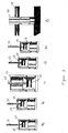
- Figures 2a and 2b show in more detail the elements of disposable part 4.
- Figure 2a shows reservoir 41 connected to valve 42 which is in a closed position so that disposable part 4 is liquid tight
- figure 2b shows the valve in an open position so that liquid may exit reservoir 41 and thus the disposable part.
- Valve 42 may be any well-known valve as long as it can be positioned from one position to another, thereby blocking or releasing the liquid substance.
- valve 42 comprises a piston 43 that is operated by a spring 44 so as to move the piston from an upper position, in which the valve is closed, see figure 2a , to a lower position in which the valve is open, see figure 2b .
- a spring 44 so as to move the piston from an upper position, in which the valve is closed, see figure 2a , to a lower position in which the valve is open, see figure 2b .
- Other means besides a spring are of course also possible to actuate the piston.
- a hydrodynamic valve as described in co-pending application EP 03019452.6 in the name of the present Applicant may be used.
- an electromechanical valve may also be used.
- FIG 3 shows stepwise the connection of capillary liquid channel 37, forming part of permanent non-disposable part 3, to valve 42, forming part of disposable part 4.
- valve 42 is in its closed position, with piston 43 in the upper position.
- Capillary channel 37 has a needle shape in this example and is positioned above the valve to allow for alignment with an insertion hole provided in valve 42 for receiving the capillary channel.
- capillary channel 37 is inserted into valve 42 which still remains in the closed, upper, position. Thus, there is still no liquid connection between the disposable part and the permanent part.
- the valve is activated by moving piston 43 to its lower position thus establishing a liquid connection between the disposable part and permanent part.
- disposable part 4 is disconnected from capillary channel 37 thus allowing for removal and replacement of the disposable part while valve 42 remains closed. No liquid will leak during this operation.
- Figure 3f shows a possible way of ensuring a correct connection between capillary channel 37 and valve 42.
- a simple click and fit connection may be used.
- a conical connector, or any other well-known connector which ensures a leak tight connection.
- the valve ensures that the disposable part is liquid tight.
- the liquid substance enters the capillary channel, and reaches space 32. Due to the use of the space in combination with an actuation means, the liquid will remain in space 32, and only exit there from once the actuation means starts vibrating.
- space 32 constitutes a capillary filling and holding chamber as well as a pressure chamber for receiving the liquid substance, in a manner as explained in the above referenced documents EP 0923957 and EP 1005916 .
- valve 42 once valve 42 is opened, liquid from reservoir 41 will flow automatically as the liquid substance will first enter valve 42, and then enter capillary channel 37 and space 32.
- a soft porous member in the channel, or also in space 32 to facilitate conveying of the liquid to space 32.
- such soft porous medium may extend beyond the liquid capillary channel 37 into space 32 of the housing, or even extend until the inner periphery of the space, or even still fill space 32.
- a support 38 see Figure 1 , may be provided for receiving the electronic means and/or electromechanical actuator 35.
- Support 38 may be formed integrally with capillary channel 37 to form the fluidic interface.
- support 38 may be a flexible electric circuit board or a PCB.
- support 38 and valve 42 will comprise means (not shown) to re-direct the excess liquid back into reservoir 41, either in the main reservoir itself, or in a separated container provided to this effect. In certain cases, it may also be necessary to avoid contamination of space 32 with a possibly different liquid substance, thus to ensure an empty space 32.
- reservoir 41 may further comprise a buffer zone which is normally empty and is arranged to receive excess liquid substance that is not ejected from said space.
- This buffer zone could be a part of the main reservoir, or a separated section in liquid contact there with.
- the reservoir itself may be a form, fill and seal reservoir, such as a simple bag, or it may be of the airless type, or even of the solid type.
- the reservoir may be provided with electronic storing means such as a layer consisting of resistors and/or capacitors elements laminated into the reservoir material.
- electronic storing means such as a layer consisting of resistors and/or capacitors elements laminated into the reservoir material.
- the exact configuration of the resistors and/or capacitors elements can thus provide information about the content of the reservoir.
- a certain resistance or capacitance may be indicative of a certain liquid substance, of the level, such as empty or not, of the liquid substance in reservoir 41, or even of the required use of the liquid substance.
- the liquid substance is a medicament
- the information could be related not only to the identification of the liquid substance, but also to its use, such as the dosage that should be expelled, the frequency thereof, its expiation date etc.
- Another way of providing this information is by using a radiofrequency identification tag (RF ID tag).
- RF ID tag radiofrequency identification tag
- the storing means may also uniquely identify the reservoir thus inhibiting the use of non-conformal reservoirs with the liquid droplet plug and spray system.
- the electronic control means may then control the ejecting of liquid from the spray device, not only by controlling the electromechanical actuation means 35, but further also by processing the information from the reservoir.
- an electronic valve control means of valve 42 may be provided to control the release of liquid substance from reservoir 41 in accordance with the information processed.
- the electronic control means 36 of permanent part 3 may also be further provided with input means for external control signals.
- the liquid droplet plug and spray device could be arranged to fit into an extension slot module of a video game playing station so as to allow for triggering of fragrances from the liquid droplet plug and spray system by the video game device which may provide signals to electronic means 36.
- liquid channel 37 may further comprise measurement means, not shown, arranged, in a suitable manner, to measure, directly or indirectly, the flow of the liquid substance through channel 37.
- measurement means are known as such, and thus are not further described here.
- such measurement could be linked to electronic control means 36 or to the valve control means to allow for opening or closing of the valve as a function of the measured flow.
- such measurement means can be calibrated precisely in a volumetric manner to stop electromechanical actuation means 35 via electronic means 36 at the instance when space 32 is empty, thus avoiding operation of electromechanical actuation means 35 longer than necessary.
- the system for atomising a liquid substance, such as perfume or medicaments, so that the system can be used for example as a nebuliser, a perfume dispenser, an inhaler, a nasal spray, or an ophthalmologic dispenser, or the like with an easily exchangeable reservoir which does not dispense any liquid substance when not in use.
- a liquid substance such as perfume or medicaments
Claims (20)
- Flüssigkeitströpfchen-Sprühsystem (1) zum Zerstäuben einer flüssigen Substanz, wie etwa einer funktionellen Flüssigkeit, die mit Arzneistoffen versetzt oder auch nicht, sterilisierend ist oder auch nicht, mit einem Duft versetzt ist oder auch nicht, mit:einer Flüssigkeitströpfchen-Sprühvorrichtung mit einem Gehäuse (31), in dem ein Raum (32) vorgesehen ist, der so eingerichtet ist, dass er die flüssige Substanz aufnimmt, wobei das Gehäuse eine perforierte Membran (33) hat, die eine oder mehrere Perforationen (34) hat und den Raum (32) so bedeckt, dass die flüssige Substanz den Raum (32) und die Vorrichtung dadurch verlassen kann, dass sie durch die eine oder mehreren Perforationen der perforierten Membran hindurchgeht;einem Behälter (41) zum Aufnehmen der flüssigen Substanz;einer Fluid-Grenzfläche mit einem Kapillarkanal (37), der so eingerichtet ist, dass er den Behälter (41) mit dem Raum (32) in dem Gehäuse verbindet, wodurch die in dem Behälter (41) enthaltene flüssige Substanz durch Kapillarwirkung zu dem Raum (32) transportiert wird;einem Ventil (42), das zwischen dem Behälter (41) und der Fluid-Grenzfläche mit dem Kapillarkanal (37) angeordnet ist, zum Steuern der Zufuhr der flüssigen Substanz aus dem Behälter (41) zu dem Kapillarkanal (37);elektromechanischen Betätigungsmitteln (35), die so eingerichtet sind, dass sie so auf die flüssige Substanz einwirken, dass ein Flüssigkeitströpfchen-Sprühnebel entsteht; undelektronischen Steuermitteln (36), die so eingerichtet sind, dass sie zumindest die elektromechanischen Betätigungsmittel (35) steuern,
wobei das Flüssigkeitströpfchen-Sprühsystem aus zwei Teilen besteht, und zwar einem ersten Teil, der ein Wegwerfteil ist und in dem der Behälter (41) und das Ventil (42) angeordnet sind, und einem zweiten Teil, der ein Nicht-Wegwerfteil ist und in dem die Flüssigkeitströpfchen-Sprühvorrichtung angeordnet ist,
dadurch gekennzeichnet, dassdie elektromechanischen Betätigungsmittel (35) so eingerichtet sind, dass sie so auf die flüssige Substanz in dem Raum (32) einwirken, dass sie in Schwingung versetzt wird und die perforierte Membran berührt, sodass sie als der Flüssigkeitströpfchen-Sprühnebel durch die eine oder mehreren Perforationen hindurchgeht, unddie elektromechanischen Betätigungsmittel (35), die elektronischen Steuermittel (36) und die Fluid-Grenzfläche mit dem Kapillarkanal (37) so angeordnet sind, dass der Behälter (41) den Kapillarkanal (37) nicht direkt berührt, die Fluid-Grenzfläche mit dem Kapillarkanal (37) das Ventil (42) direkt berührt, das Ventil (42) den Behälter (41) direkt berührt und das Ventil (42) gewährleistet, dass der erste Teil, der ein Wegwerfteil ist, flüssigkeitsdicht ist, wenn er nicht in Gebrauch ist. - Flüssigkeitströpfchen-Sprühsystem nach Anspruch 1, dadurch gekennzeichnet, dass die Fluid-Grenzfläche (37) ein weiches poröses Medium enthält, das den Transport der flüssigen Substanz erleichtern kann.
- Flüssigkeitströpfchen-Sprühsystem nach Anspruch 2, dadurch gekennzeichnet, dass sich das weiche poröse Medium über die Fluid-Grenzfläche (37) hinaus in den Raum (32) des Gehäuses erstreckt.
- Flüssigkeitströpfchen-Sprühsystem nach Anspruch 3, dadurch gekennzeichnet, dass sich das weiche poröse Medium bis zu der Innenperipherie des Raums (32) erstreckt.
- Flüssigkeitströpfchen-Sprühsystem nach Anspruch 4, dadurch gekennzeichnet, dass das weiche poröse Medium den Raum (32) ausfüllt.
- Flüssigkeitströpfchen-Sprühsystem nach einem der vorhergehenden Ansprüche, dadurch gekennzeichnet, dass die Fluid-Grenzfläche (37) an dem zweiten Teil, der ein Nicht-Wegwerfteil ist, weiterhin einen Träger (38) zum Aufnehmen der elektronischen Mittel und/oder der elektromechanischen Betätigungsmittel (35) aufweist.
- Flüssigkeitströpfchen-Sprühsystem nach Anspruch 6, dadurch gekennzeichnet, dass der Träger (38) eine flexible elektrische Schaltkreisplatte ist.
- Flüssigkeitströpfchen-Sprühsystem nach Anspruch 6, dadurch gekennzeichnet, dass der Träger (38) eine Leiterplatte ist.
- Flüssigkeitströpfchen-Sprühsystem nach einem der vorhergehenden Ansprüche, dadurch gekennzeichnet, dass der Behälter (41) weiterhin eine Pufferzone aufweist, die normalerweise leer ist und so eingerichtet ist, dass sie überschüssige flüssige Substanz aufnimmt, die nicht aus dem Raum (32) ausgestoßen wird.
- Flüssigkeitströpfchen-Sprühsystem nach einem der vorhergehenden Ansprüche, dadurch gekennzeichnet, dass die Fluid-Grenzfläche (37) weiterhin Mittel zum Zurückführen von überschüssiger flüssiger Substanz zurück zu dem Behälter (41) aufweist.
- Flüssigkeitströpfchen-Sprühsystem nach einem der vorhergehenden Ansprüche, dadurch gekennzeichnet, dass der Flüssigkeitskanal weiterhin Messmittel aufweist, die so eingerichtet sind, dass sie in einer geeigneten Weise direkt oder indirekt den Durchsatz der flüssigen Substanz durch den Kanal messen.
- Flüssigkeitströpfchen-Sprühsystem nach einem der vorhergehenden Ansprüche, dadurch gekennzeichnet, dass der Behälter (41) ein Behälter zum Formen, Füllen und Verschließen, ein luftloser Behälter oder ein massiver Behälter ist.
- Flüssigkeitströpfchen-Sprühsystem nach einem der vorhergehenden Ansprüche, dadurch gekennzeichnet, dass zumindest ein Teil des Behälters (41) in einer geeigneten Weise mit Speichermitteln versehen ist, die so eingerichtet sind, dass sie Informationen zur Identifikation des Inhalts des Behälters (41) und zur Verwendung des Inhalts speichern.
- Flüssigkeitströpfchen-Sprühsystem nach Anspruch 13, dadurch gekennzeichnet, dass die Speichermittel Informationen speichern, die den Füllstand des Inhalts des Behälters (41) angeben.
- Flüssigkeitströpfchen-Sprühsystem nach Anspruch 13 oder 14, dadurch gekennzeichnet, dass die Speichermittel eine Folie sind, die eine Schicht aus Widerstands- und/oder Kondensator-Elementen enthält, die in zumindest einem Teil des Behälters (41) aufeinander geschichtet sind.
- Flüssigkeitströpfchen-Sprühsystem nach einem der vorhergehenden Ansprüche, dadurch gekennzeichnet, dass die elektronischen Mittel (36) weiterhin die Abgabe der flüssigen Substanz aus der Flüssigkeitströpfchen-Sprühvorrichtung steuern.
- Flüssigkeitströpfchen-Sprühsystem nach einem der vorhergehenden Ansprüche, das weiterhin Ventilsteuermittel zum Steuern des Öffnens und Schließens des Ventils (42) aufweist.
- Flüssigkeitströpfchen-Sprühsystem nach Anspruch 17, dadurch gekennzeichnet, dass die elektronischen Mittel (36) weiterhin die Abgabe der flüssigen Substanz aus dem Behälter (41) in den Raum (32) dadurch steuern, dass sie die Ventilsteuermittel steuern.
- Flüssigkeitströpfchen-Sprühsystem nach Anspruch 16, 17 oder 18, dadurch gekennzeichnet, dass die elektronischen Steuermittel (36) auf externe Signale zum Auslösen der Abgabe der flüssigen Substanz reagieren.
- Flüssigkeitströpfchen-Sprühsystem nach einem der Ansprüche 16 oder 17, die Unteransprüche von Anspruch 11 sind, oder nach Anspruch 18, dadurch gekennzeichnet, dass die elektronischen Steuermittel (36) auf Signale, von den Messmitteln, zum Auslösen und Unterbrechen der Abgabe der flüssigen Substanz reagieren.
Priority Applications (5)
| Application Number | Priority Date | Filing Date | Title |
|---|---|---|---|
| AT04001566T ATE510566T1 (de) | 2004-01-26 | 2004-01-26 | Zerstäubungssystem für flüssigkeiten |
| EP04001566A EP1559436B1 (de) | 2004-01-26 | 2004-01-26 | Zerstäubungssystem für Flüssigkeiten |
| ES04001566T ES2367260T3 (es) | 2004-01-26 | 2004-01-26 | Sistema de pulverización para atomizar líquidos. |
| US11/037,473 US7694892B2 (en) | 2004-01-26 | 2005-01-19 | Liquid droplet plug and spray system |
| JP2005014897A JP4809609B2 (ja) | 2004-01-26 | 2005-01-21 | 液滴スプレーシステム |
Applications Claiming Priority (1)
| Application Number | Priority Date | Filing Date | Title |
|---|---|---|---|
| EP04001566A EP1559436B1 (de) | 2004-01-26 | 2004-01-26 | Zerstäubungssystem für Flüssigkeiten |
Publications (2)
| Publication Number | Publication Date |
|---|---|
| EP1559436A1 EP1559436A1 (de) | 2005-08-03 |
| EP1559436B1 true EP1559436B1 (de) | 2011-05-25 |
Family
ID=34639373
Family Applications (1)
| Application Number | Title | Priority Date | Filing Date |
|---|---|---|---|
| EP04001566A Expired - Lifetime EP1559436B1 (de) | 2004-01-26 | 2004-01-26 | Zerstäubungssystem für Flüssigkeiten |
Country Status (5)
| Country | Link |
|---|---|
| US (1) | US7694892B2 (de) |
| EP (1) | EP1559436B1 (de) |
| JP (1) | JP4809609B2 (de) |
| AT (1) | ATE510566T1 (de) |
| ES (1) | ES2367260T3 (de) |
Families Citing this family (15)
| Publication number | Priority date | Publication date | Assignee | Title |
|---|---|---|---|---|
| US7538473B2 (en) * | 2004-02-03 | 2009-05-26 | S.C. Johnson & Son, Inc. | Drive circuits and methods for ultrasonic piezoelectric actuators |
| US7723899B2 (en) | 2004-02-03 | 2010-05-25 | S.C. Johnson & Son, Inc. | Active material and light emitting device |
| US7824627B2 (en) | 2004-02-03 | 2010-11-02 | S.C. Johnson & Son, Inc. | Active material and light emitting device |
| EP1604701B1 (de) | 2004-06-09 | 2010-12-15 | Microflow Engineering SA | Verbessertes modulares Flüssigkeitssprühsystem |
| FR2911783B1 (fr) * | 2007-01-31 | 2012-02-03 | Jacques Jean Luc Dalibard | Dispositif sanitaire de pulverisation de liquides securise |
| EP2050478A1 (de) | 2007-10-16 | 2009-04-22 | GE Healthcare Finland Oy | Vorrichtung zur Weiterleitung und Regulierung flüchtiger Fluide in ein Inspirationsgas |
| US20100001090A1 (en) | 2008-07-03 | 2010-01-07 | Arthur Hampton Neergaard | Liquid Particle Emitting Device |
| EP2501493B1 (de) | 2009-11-18 | 2018-08-22 | Reckitt Benckiser LLC | Vorrichtung und verfahren zur toilettenbehandlung |
| WO2011061479A1 (en) | 2009-11-18 | 2011-05-26 | Reckitt Benckiser Llc | Ultrasonic surface treatment device and method |
| AU2010340769B2 (en) | 2010-01-11 | 2015-02-12 | Koninklijke Philips Electronics N.V. | Magnetic coupling for aerosol generating apparatus |
| EP2523709B1 (de) | 2010-01-11 | 2016-06-15 | Koninklijke Philips N.V. | Magnetkopplung für aerosolerzeugungsvorrichtung |
| PL2707549T3 (pl) | 2011-05-13 | 2015-08-31 | Unilever Nv | Urządzenie rozpylające |
| CA2908158A1 (en) * | 2013-04-04 | 2014-10-09 | The United States Of America, As Represented By The Secretary, Department Of Health And Human Services, Centers For Disease Control And Prevention | Nasal aerosol delivery system |
| GB201312263D0 (en) | 2013-07-09 | 2013-08-21 | The Technology Partnership Plc | Separable membrane improvements |
| GB201316314D0 (en) | 2013-09-13 | 2013-10-30 | The Technology Partnership Plc | Fluid management for vibration perforate membrane spray systems |
Family Cites Families (13)
| Publication number | Priority date | Publication date | Assignee | Title |
|---|---|---|---|---|
| JPS61141955A (ja) * | 1984-12-14 | 1986-06-28 | Matsushita Electric Ind Co Ltd | 液体噴射装置 |
| WO1992011050A1 (en) * | 1990-12-17 | 1992-07-09 | Minnesota Mining And Manufacturing Company | Inhaler |
| US5404871A (en) * | 1991-03-05 | 1995-04-11 | Aradigm | Delivery of aerosol medications for inspiration |
| JPH04279172A (ja) * | 1991-03-05 | 1992-10-05 | Koji Toda | 超音波眼液噴霧装置 |
| US5938117A (en) * | 1991-04-24 | 1999-08-17 | Aerogen, Inc. | Methods and apparatus for dispensing liquids as an atomized spray |
| WO1993010910A1 (en) | 1991-12-04 | 1993-06-10 | The Technology Partnership Limited | Fluid droplet production apparatus and method |
| GB2272389B (en) | 1992-11-04 | 1996-07-24 | Bespak Plc | Dispensing apparatus |
| US5758637A (en) * | 1995-08-31 | 1998-06-02 | Aerogen, Inc. | Liquid dispensing apparatus and methods |
| US6427682B1 (en) | 1995-04-05 | 2002-08-06 | Aerogen, Inc. | Methods and apparatus for aerosolizing a substance |
| US5749519A (en) | 1996-12-13 | 1998-05-12 | S. C. Johnson & Son, Inc. | Liquid air freshener dispenser device with nonporous wicking means |
| EP1129741B1 (de) * | 1997-11-19 | 2006-04-12 | Microflow Engineering SA | Sprühvorrichtung für einen Inhalator |
| EP1005916A1 (de) | 1998-12-01 | 2000-06-07 | Microflow Engineering SA | Inhalator mit Ultraschallzerstäuber dessen Düsenöffnungen den Amplitudenmaxima eines stehenden Wellenmusters überlagert sind |
| FR2817844B1 (fr) | 2000-12-08 | 2003-03-28 | Valois Sa | Distributeur de produit fluide |
-
2004
- 2004-01-26 EP EP04001566A patent/EP1559436B1/de not_active Expired - Lifetime
- 2004-01-26 ES ES04001566T patent/ES2367260T3/es not_active Expired - Lifetime
- 2004-01-26 AT AT04001566T patent/ATE510566T1/de not_active IP Right Cessation
-
2005
- 2005-01-19 US US11/037,473 patent/US7694892B2/en active Active
- 2005-01-21 JP JP2005014897A patent/JP4809609B2/ja not_active Expired - Fee Related
Also Published As
| Publication number | Publication date |
|---|---|
| ES2367260T3 (es) | 2011-10-31 |
| US7694892B2 (en) | 2010-04-13 |
| JP4809609B2 (ja) | 2011-11-09 |
| EP1559436A1 (de) | 2005-08-03 |
| JP2005205410A (ja) | 2005-08-04 |
| US20050230495A1 (en) | 2005-10-20 |
| ATE510566T1 (de) | 2011-06-15 |
Similar Documents
| Publication | Publication Date | Title |
|---|---|---|
| US7694892B2 (en) | Liquid droplet plug and spray system | |
| EP1604701B1 (de) | Verbessertes modulares Flüssigkeitssprühsystem | |
| EP1468749B1 (de) | Flüssigkeitströpfchen- Spritzvorrichtung und Düsenkörper | |
| KR100264246B1 (ko) | 분배 장치 | |
| AU2020269970B2 (en) | Electronic aerosol provision system | |
| US9604242B2 (en) | Volatile liquid droplet dispenser device | |
| RU2559171C2 (ru) | Системы ингалятора с бесконсервантной разовой дозой | |
| US20160354799A1 (en) | Microfluidic delivery system for releasing fluid compositions | |
| JP2019513012A5 (de) | ||
| JP2007526037A (ja) | 揮発性物質の可制御放出 | |
| US20100205727A1 (en) | Toilet Flusher having Substance Dispensing Activated By Sensor Directed at Flush Water | |
| EP2388076B1 (de) | Wasserdichte Duftabgabevorrichtung | |
| JP4543028B2 (ja) | 香料または芳香剤の分注装置 | |
| CN217429273U (zh) | 供液组件、主机和电子雾化装置 | |
| CN114513974A (zh) | 用于插入印刷广告传单的样品泵装置 | |
| EP1510261A1 (de) | Tropfensprühvorrichtung mit hydrodynamischem Ventil |
Legal Events
| Date | Code | Title | Description |
|---|---|---|---|
| PUAI | Public reference made under article 153(3) epc to a published international application that has entered the european phase |
Free format text: ORIGINAL CODE: 0009012 |
|
| AK | Designated contracting states |
Kind code of ref document: A1 Designated state(s): AT BE BG CH CY CZ DE DK EE ES FI FR GB GR HU IE IT LI LU MC NL PT RO SE SI SK TR |
|
| AX | Request for extension of the european patent |
Extension state: AL LT LV MK |
|
| 17P | Request for examination filed |
Effective date: 20051216 |
|
| REG | Reference to a national code |
Ref country code: HK Ref legal event code: DE Ref document number: 1078499 Country of ref document: HK |
|
| AKX | Designation fees paid |
Designated state(s): AT BE BG CH CY CZ DE DK EE ES FI FR GB GR HU IE IT LI LU MC NL PT RO SE SI SK TR |
|
| 17Q | First examination report despatched |
Effective date: 20080703 |
|
| GRAP | Despatch of communication of intention to grant a patent |
Free format text: ORIGINAL CODE: EPIDOSNIGR1 |
|
| GRAS | Grant fee paid |
Free format text: ORIGINAL CODE: EPIDOSNIGR3 |
|
| GRAA | (expected) grant |
Free format text: ORIGINAL CODE: 0009210 |
|
| RAP1 | Party data changed (applicant data changed or rights of an application transferred) |
Owner name: EP SYSTEMS SA |
|
| AK | Designated contracting states |
Kind code of ref document: B1 Designated state(s): AT BE BG CH CY CZ DE DK EE ES FI FR GB GR HU IE IT LI LU MC NL PT RO SE SI SK TR |
|
| REG | Reference to a national code |
Ref country code: GB Ref legal event code: FG4D |
|
| REG | Reference to a national code |
Ref country code: CH Ref legal event code: EP |
|
| REG | Reference to a national code |
Ref country code: IE Ref legal event code: FG4D |
|
| REG | Reference to a national code |
Ref country code: DE Ref legal event code: R096 Ref document number: 602004032804 Country of ref document: DE Effective date: 20110707 |
|
| REG | Reference to a national code |
Ref country code: CH Ref legal event code: NV Representative=s name: NOVAGRAAF INTERNATIONAL SA |
|
| REG | Reference to a national code |
Ref country code: NL Ref legal event code: VDEP Effective date: 20110525 |
|
| PG25 | Lapsed in a contracting state [announced via postgrant information from national office to epo] |
Ref country code: PT Free format text: LAPSE BECAUSE OF FAILURE TO SUBMIT A TRANSLATION OF THE DESCRIPTION OR TO PAY THE FEE WITHIN THE PRESCRIBED TIME-LIMIT Effective date: 20110926 Ref country code: SE Free format text: LAPSE BECAUSE OF FAILURE TO SUBMIT A TRANSLATION OF THE DESCRIPTION OR TO PAY THE FEE WITHIN THE PRESCRIBED TIME-LIMIT Effective date: 20110525 |
|
| REG | Reference to a national code |
Ref country code: ES Ref legal event code: FG2A Ref document number: 2367260 Country of ref document: ES Kind code of ref document: T3 Effective date: 20111031 |
|
| PG25 | Lapsed in a contracting state [announced via postgrant information from national office to epo] |
Ref country code: GR Free format text: LAPSE BECAUSE OF FAILURE TO SUBMIT A TRANSLATION OF THE DESCRIPTION OR TO PAY THE FEE WITHIN THE PRESCRIBED TIME-LIMIT Effective date: 20110826 Ref country code: AT Free format text: LAPSE BECAUSE OF FAILURE TO SUBMIT A TRANSLATION OF THE DESCRIPTION OR TO PAY THE FEE WITHIN THE PRESCRIBED TIME-LIMIT Effective date: 20110525 Ref country code: CY Free format text: LAPSE BECAUSE OF FAILURE TO SUBMIT A TRANSLATION OF THE DESCRIPTION OR TO PAY THE FEE WITHIN THE PRESCRIBED TIME-LIMIT Effective date: 20110525 Ref country code: SI Free format text: LAPSE BECAUSE OF FAILURE TO SUBMIT A TRANSLATION OF THE DESCRIPTION OR TO PAY THE FEE WITHIN THE PRESCRIBED TIME-LIMIT Effective date: 20110525 Ref country code: FI Free format text: LAPSE BECAUSE OF FAILURE TO SUBMIT A TRANSLATION OF THE DESCRIPTION OR TO PAY THE FEE WITHIN THE PRESCRIBED TIME-LIMIT Effective date: 20110525 Ref country code: BE Free format text: LAPSE BECAUSE OF FAILURE TO SUBMIT A TRANSLATION OF THE DESCRIPTION OR TO PAY THE FEE WITHIN THE PRESCRIBED TIME-LIMIT Effective date: 20110525 |
|
| PG25 | Lapsed in a contracting state [announced via postgrant information from national office to epo] |
Ref country code: NL Free format text: LAPSE BECAUSE OF FAILURE TO SUBMIT A TRANSLATION OF THE DESCRIPTION OR TO PAY THE FEE WITHIN THE PRESCRIBED TIME-LIMIT Effective date: 20110525 |
|
| PG25 | Lapsed in a contracting state [announced via postgrant information from national office to epo] |
Ref country code: EE Free format text: LAPSE BECAUSE OF FAILURE TO SUBMIT A TRANSLATION OF THE DESCRIPTION OR TO PAY THE FEE WITHIN THE PRESCRIBED TIME-LIMIT Effective date: 20110525 Ref country code: CZ Free format text: LAPSE BECAUSE OF FAILURE TO SUBMIT A TRANSLATION OF THE DESCRIPTION OR TO PAY THE FEE WITHIN THE PRESCRIBED TIME-LIMIT Effective date: 20110525 |
|
| PG25 | Lapsed in a contracting state [announced via postgrant information from national office to epo] |
Ref country code: SK Free format text: LAPSE BECAUSE OF FAILURE TO SUBMIT A TRANSLATION OF THE DESCRIPTION OR TO PAY THE FEE WITHIN THE PRESCRIBED TIME-LIMIT Effective date: 20110525 Ref country code: DK Free format text: LAPSE BECAUSE OF FAILURE TO SUBMIT A TRANSLATION OF THE DESCRIPTION OR TO PAY THE FEE WITHIN THE PRESCRIBED TIME-LIMIT Effective date: 20110525 Ref country code: RO Free format text: LAPSE BECAUSE OF FAILURE TO SUBMIT A TRANSLATION OF THE DESCRIPTION OR TO PAY THE FEE WITHIN THE PRESCRIBED TIME-LIMIT Effective date: 20110525 |
|
| PLBE | No opposition filed within time limit |
Free format text: ORIGINAL CODE: 0009261 |
|
| STAA | Information on the status of an ep patent application or granted ep patent |
Free format text: STATUS: NO OPPOSITION FILED WITHIN TIME LIMIT |
|
| 26N | No opposition filed |
Effective date: 20120228 |
|
| PG25 | Lapsed in a contracting state [announced via postgrant information from national office to epo] |
Ref country code: IT Free format text: LAPSE BECAUSE OF FAILURE TO SUBMIT A TRANSLATION OF THE DESCRIPTION OR TO PAY THE FEE WITHIN THE PRESCRIBED TIME-LIMIT Effective date: 20110525 |
|
| REG | Reference to a national code |
Ref country code: DE Ref legal event code: R097 Ref document number: 602004032804 Country of ref document: DE Effective date: 20120228 |
|
| PG25 | Lapsed in a contracting state [announced via postgrant information from national office to epo] |
Ref country code: MC Free format text: LAPSE BECAUSE OF NON-PAYMENT OF DUE FEES Effective date: 20120131 |
|
| REG | Reference to a national code |
Ref country code: HK Ref legal event code: WD Ref document number: 1078499 Country of ref document: HK |
|
| REG | Reference to a national code |
Ref country code: IE Ref legal event code: MM4A |
|
| PG25 | Lapsed in a contracting state [announced via postgrant information from national office to epo] |
Ref country code: IE Free format text: LAPSE BECAUSE OF NON-PAYMENT OF DUE FEES Effective date: 20120126 |
|
| PG25 | Lapsed in a contracting state [announced via postgrant information from national office to epo] |
Ref country code: BG Free format text: LAPSE BECAUSE OF FAILURE TO SUBMIT A TRANSLATION OF THE DESCRIPTION OR TO PAY THE FEE WITHIN THE PRESCRIBED TIME-LIMIT Effective date: 20110825 |
|
| PG25 | Lapsed in a contracting state [announced via postgrant information from national office to epo] |
Ref country code: TR Free format text: LAPSE BECAUSE OF FAILURE TO SUBMIT A TRANSLATION OF THE DESCRIPTION OR TO PAY THE FEE WITHIN THE PRESCRIBED TIME-LIMIT Effective date: 20110525 |
|
| PG25 | Lapsed in a contracting state [announced via postgrant information from national office to epo] |
Ref country code: LU Free format text: LAPSE BECAUSE OF NON-PAYMENT OF DUE FEES Effective date: 20120126 |
|
| PG25 | Lapsed in a contracting state [announced via postgrant information from national office to epo] |
Ref country code: HU Free format text: LAPSE BECAUSE OF FAILURE TO SUBMIT A TRANSLATION OF THE DESCRIPTION OR TO PAY THE FEE WITHIN THE PRESCRIBED TIME-LIMIT Effective date: 20040126 |
|
| REG | Reference to a national code |
Ref country code: CH Ref legal event code: PUE Owner name: APTAR FRANCE SAS, FR Free format text: FORMER OWNER: EP SYSTEMS SA, CH |
|
| PGFP | Annual fee paid to national office [announced via postgrant information from national office to epo] |
Ref country code: CH Payment date: 20141216 Year of fee payment: 12 Ref country code: GB Payment date: 20141117 Year of fee payment: 12 |
|
| REG | Reference to a national code |
Ref country code: DE Ref legal event code: R082 Ref document number: 602004032804 Country of ref document: DE Representative=s name: TBK, DE |
|
| REG | Reference to a national code |
Ref country code: GB Ref legal event code: 732E Free format text: REGISTERED BETWEEN 20150212 AND 20150219 |
|
| REG | Reference to a national code |
Ref country code: FR Ref legal event code: TP Owner name: APTAR FRANCE SAS, FR Effective date: 20150310 |
|
| REG | Reference to a national code |
Ref country code: DE Ref legal event code: R082 Ref document number: 602004032804 Country of ref document: DE Representative=s name: TBK, DE Effective date: 20150306 Ref country code: DE Ref legal event code: R081 Ref document number: 602004032804 Country of ref document: DE Owner name: APTAR FRANCE SAS, FR Free format text: FORMER OWNER: EP SYSTEMS SA, NEUCHATEL, CH Effective date: 20150306 Ref country code: DE Ref legal event code: R081 Ref document number: 602004032804 Country of ref document: DE Owner name: APTAR FRANCE SAS, FR Free format text: FORMER OWNER: MICROFLOW ENGINEERING S.A., PESEUX, CH Effective date: 20110428 |
|
| REG | Reference to a national code |
Ref country code: ES Ref legal event code: PC2A Owner name: APTAR FRANCE SAS Effective date: 20150423 |
|
| PGFP | Annual fee paid to national office [announced via postgrant information from national office to epo] |
Ref country code: ES Payment date: 20150128 Year of fee payment: 12 Ref country code: DE Payment date: 20141031 Year of fee payment: 12 |
|
| REG | Reference to a national code |
Ref country code: FR Ref legal event code: PLFP Year of fee payment: 13 |
|
| REG | Reference to a national code |
Ref country code: DE Ref legal event code: R119 Ref document number: 602004032804 Country of ref document: DE |
|
| REG | Reference to a national code |
Ref country code: CH Ref legal event code: PL |
|
| GBPC | Gb: european patent ceased through non-payment of renewal fee |
Effective date: 20160126 |
|
| PG25 | Lapsed in a contracting state [announced via postgrant information from national office to epo] |
Ref country code: DE Free format text: LAPSE BECAUSE OF NON-PAYMENT OF DUE FEES Effective date: 20160802 Ref country code: GB Free format text: LAPSE BECAUSE OF NON-PAYMENT OF DUE FEES Effective date: 20160126 Ref country code: LI Free format text: LAPSE BECAUSE OF NON-PAYMENT OF DUE FEES Effective date: 20160131 Ref country code: CH Free format text: LAPSE BECAUSE OF NON-PAYMENT OF DUE FEES Effective date: 20160131 |
|
| REG | Reference to a national code |
Ref country code: FR Ref legal event code: PLFP Year of fee payment: 14 |
|
| REG | Reference to a national code |
Ref country code: ES Ref legal event code: FD2A Effective date: 20170224 |
|
| PG25 | Lapsed in a contracting state [announced via postgrant information from national office to epo] |
Ref country code: ES Free format text: LAPSE BECAUSE OF NON-PAYMENT OF DUE FEES Effective date: 20160127 |
|
| REG | Reference to a national code |
Ref country code: FR Ref legal event code: PLFP Year of fee payment: 15 |
|
| PGFP | Annual fee paid to national office [announced via postgrant information from national office to epo] |
Ref country code: FR Payment date: 20210126 Year of fee payment: 18 |
|
| PG25 | Lapsed in a contracting state [announced via postgrant information from national office to epo] |
Ref country code: FR Free format text: LAPSE BECAUSE OF NON-PAYMENT OF DUE FEES Effective date: 20220131 |