EP1559308B1 - Round baler - Google Patents
Round baler Download PDFInfo
- Publication number
- EP1559308B1 EP1559308B1 EP04001653A EP04001653A EP1559308B1 EP 1559308 B1 EP1559308 B1 EP 1559308B1 EP 04001653 A EP04001653 A EP 04001653A EP 04001653 A EP04001653 A EP 04001653A EP 1559308 B1 EP1559308 B1 EP 1559308B1
- Authority
- EP
- European Patent Office
- Prior art keywords
- rolls
- assembly
- round baler
- baling
- chassis
- Prior art date
- Legal status (The legal status is an assumption and is not a legal conclusion. Google has not performed a legal analysis and makes no representation as to the accuracy of the status listed.)
- Expired - Lifetime
Links
- 238000000034 method Methods 0.000 claims description 5
- 238000005520 cutting process Methods 0.000 claims description 3
- 238000005303 weighing Methods 0.000 claims description 3
- 230000000712 assembly Effects 0.000 description 8
- 238000000429 assembly Methods 0.000 description 8
- 238000012423 maintenance Methods 0.000 description 2
- 238000010276 construction Methods 0.000 description 1
- 230000008878 coupling Effects 0.000 description 1
- 238000010168 coupling process Methods 0.000 description 1
- 238000005859 coupling reaction Methods 0.000 description 1
- 238000009434 installation Methods 0.000 description 1
- 238000004519 manufacturing process Methods 0.000 description 1
- 239000002184 metal Substances 0.000 description 1
Images


Classifications
-
- A—HUMAN NECESSITIES
- A01—AGRICULTURE; FORESTRY; ANIMAL HUSBANDRY; HUNTING; TRAPPING; FISHING
- A01F—PROCESSING OF HARVESTED PRODUCE; HAY OR STRAW PRESSES; DEVICES FOR STORING AGRICULTURAL OR HORTICULTURAL PRODUCE
- A01F15/00—Baling presses for straw, hay or the like
- A01F15/07—Rotobalers, i.e. machines for forming cylindrical bales by winding and pressing
-
- A—HUMAN NECESSITIES
- A01—AGRICULTURE; FORESTRY; ANIMAL HUSBANDRY; HUNTING; TRAPPING; FISHING
- A01F—PROCESSING OF HARVESTED PRODUCE; HAY OR STRAW PRESSES; DEVICES FOR STORING AGRICULTURAL OR HORTICULTURAL PRODUCE
- A01F15/00—Baling presses for straw, hay or the like
- A01F15/08—Details
- A01F15/18—Endless belts, rolls or the like
-
- A—HUMAN NECESSITIES
- A01—AGRICULTURE; FORESTRY; ANIMAL HUSBANDRY; HUNTING; TRAPPING; FISHING
- A01F—PROCESSING OF HARVESTED PRODUCE; HAY OR STRAW PRESSES; DEVICES FOR STORING AGRICULTURAL OR HORTICULTURAL PRODUCE
- A01F15/00—Baling presses for straw, hay or the like
- A01F15/07—Rotobalers, i.e. machines for forming cylindrical bales by winding and pressing
- A01F2015/078—Pressing chamber formed exclusively by flexible elements, e.g. belts
-
- A—HUMAN NECESSITIES
- A01—AGRICULTURE; FORESTRY; ANIMAL HUSBANDRY; HUNTING; TRAPPING; FISHING
- A01F—PROCESSING OF HARVESTED PRODUCE; HAY OR STRAW PRESSES; DEVICES FOR STORING AGRICULTURAL OR HORTICULTURAL PRODUCE
- A01F15/00—Baling presses for straw, hay or the like
- A01F15/07—Rotobalers, i.e. machines for forming cylindrical bales by winding and pressing
- A01F2015/0795—Pressing chamber with variable volume
Definitions
- This invention relates to a round baler comprising a chassis and a baling assembly, whereas the baling assembly comprises side structures separated from each other, cross beams connecting the side structures, rolls rotatably journalled in these side structures and/or on a tensioning arm and belts or the like, trained over said rolls and it relates to a method to install endless belts on a round baler.
- WO-A1-98/17097 discloses a round baler with side walls, rolls and belts, to the lower front end of which is attached a pick-up. In order to install the belts, they have to be finite and pulled at one end over all rolls and partly through gaps between adjacent rolls. When this is done, the ends of the belts are connected to each other. Since this work is cumbersome and since belt connectors are a source for costs and problems it would be desirous to use endless belts.
- transverse struts are located such that they are located inside a space surrounded by a chain-slat conveyor.
- the front walls form a single unit together with the tonque and the chassis and are connected to the rear housing, such that again the chain-slat conveyor can only be installed as a string to be routed over and between the rolls, and the ends of which are connected finally to each other.
- the problem this invention is based on is the impossibility to install endless belts on such type of a baler.
- the circumferential sides (front, rear, bottom, up) of the baling assembly are free and endless belts can be moved like a ring laterally over the baling assembly and than concentrated towards the bale chamber.
- No chassis cross beam and no tying or net wrapping assembly obstruct the path of the belt(s).
- At the end one or more releasably journalled rolls can be brought into their position, which apply the belts to the rolls already in place and tighten them.
- belts which are made endless from the very beginning, finite belts, the ends of which are connected can be used as well.
- the side structure may be formed from side walls, i.e sheet metal surfaces or by arms, by a frame or the like as this is disclosed in EP-A1-1 308 078 or EP-A1-1 285 571 .
- baling assembly as a single and self-sufficient unit is even easier to do, if all other applying forces resulting from pulling the round baler over the field and from the weight and operation of all components are assumed by a chassis with wheels and a tongue, to which the baling assembly is connected. In such a case interfaces are provided at the chassis and the baling assembly, which easily can get separated. As another advantage various baling assemblies may get connected to such a chassis.
- All known types of crop receiving and/or processing assemblies can be attached to the carrying structure either alone or in combination with each other. Since they are not connected to the baling assembly directly, the belts can be moved like a ring over the baling assembly, once it is lifted from the chassis. Height adjustment devices, like hydraulic actuators would act between the carrying structure and the respective crop receiving and/or processing assembly to move it into one or several operative positions and into an inoperative position.
- bale handling assemblies can be attached to the carrying structure, like a bale wrapping means, a bale weighing means, a bale unloading means, a bale tying or netting means, etc., again either alone or in combination with each other.
- bale handling assemblies would often be attached to the baling assembly and obstruct the way of belts moved ringwise over the baling assembly.
- baler Since with known balers it is normally a front part, which does not need adoption to another size or type of the rear part of the baler, it reduces assembly efforts, if said front part is fixed to the carrying structure, whereas a rear part is adapted to and fixed to said front part.
- a round baler may have a front part with different settings of rolls, to which may be attached one of a set of different rear parts, with belts on rolls with different settings. This however does not exclude, that both - the front and the rear part - are attached to the carrying structure, such that in the case of a round baler the rear part is hinged to the carrying structure rather than to the front part.
- the belts can be pressed onto the rolls and the lately installed rolls to press the belts on the rolls already in place, can be brought in place in a fixed structure of the baling assembly, if some of the rolls are replaceable while the structures are in place, in particular by means of shafts or stub shafts connectable to a roll body.
- Freeing the circumference of the baling assembly may happen by disconnecting the whole baling assembly from the carrying structure and by lifting it therefrom by means of a crane or the like. Or access can be provided, if the baling assembly is hinged to the carrying structure such, that it can be tilted laterally about an axis extending substantially in the longitudinal direction of the baler. Latter solution does not require a crane but could be performed also with a jack stand or hydraulic actuator. The baling assembly would always remain connected to the carrying structure and could easily be returned to the initial position.
- a tilting movement or even a removal of the baling assembly from the carrying structure is easy to accomplish, if the drives are easy to disconnect, like with chains, universal joint shafts, clutches etc., when disconnection is needed. Alternatively hydraulic hoses and couplings may be used. If the drives are present on the side, where the baling assembly is hinged to the carrying structure, universal joint shafts, universal joints, hydraulic or electric cables or the like may be provided, which retain the connection even in the tilted position.
- a fast way to install endless belts on a baling assembly of a round baler is seen in following method, namely a) the baling assembly is put into a position in which the rolls are radially free to the outside, b) the belt is moved as a ring over the baling assembly, c) at least one loop is formed by the belt and a roll is moved into this loop and fixed at the side structures to thereby apply the belt to the rolls and d)a tensioning device is applied to either moveable rolls and/or to a belt strand between two rolls.
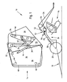
- FIG. 1 shows a baler 10, having a chassis 12, a baling assembly 14, a crop receiving and/or processing assembly 16 and a bale handling assembly 18.
- the baler 10 as shown is in the form of a round baler of the variable chamber type.
- the baler 10 is of the pull type, i.e. it gets attached to a tractor (not shown) or the like and is pulled during operation and transport.
- the chassis 12 comprises a carrying structure 20, wheels 22 and a tongue 24.
- the chassis 12 is of a self-carrying structure to which all assemblies of the baler 10 can be attached.
- the carrying structure 20 is made of beams, traverses, struts, axles, cross beams, etc. welded or bolted together to form a rigid piece.
- the carrying structure 20 is formed such, that it can assume in an inner space or on its top side the baling assembly 14, at its underside the crop receiving and/or processing assembly 16 and normally at the back side or above the crop receiving and/or processing assembly 16 a bale handling assembly 18.
- the bale handling assembly 18 could be installed on any place which fits the purpose.
- Flanges or other interface connecting means are provided at places which are useful to receive either of the above assemblies 14, 16, 18.
- the carrying structure 20 extends under an angle of about 45 degrees to the ground on which it stands and is connected to the tongue 24 at one end and to the wheels 22 at the other end.
- Two beams extend on each side in the longitudinal direction of the baler 10 and are interconnected by means of cross beams (not shown).
- a recess 26 Provided at the underside of the carrying structure 20 is a recess 26 to provide additional space for the crop receiving and/or processing assembly 16. Such a recess 26 or additional space may not be needed in other embodiments.
- the carrying structure 20 here is shown in straight lines, it is obvious, that it may be of a different shape and layout, when this is necessary.
- the carrying structure 20 may be formed such, that the baling assembly 14 is not fastened to its upper side, but is suspended from a portion high up.
- the carrying structure 20 is also provided with electronic controls (not shown) and drives 56 in the form of belts, chains, gears or hydraulic drives, whereas the one shown comprises a bevel gear with an universal joint.
- drives 56 in the form of belts, chains, gears or hydraulic drives, whereas the one shown comprises a bevel gear with an universal joint.
- a bottom roll 58 is rotatably received by the carrying structure 20. This bottom roll 58 is oriented and located such, that it can support a round bale formed in this baling assembly 14.
- the wheels 22 are rotatably connected to the carrying structure 20 either directly or via an axle (not shown).
- the wheels 22 may be arranged in tandem fashion, spring suspended or fixed, steerable or straight and with or without brakes.
- the arrangement of the wheels 22 is such, that the baling assembly 14 in question can be readily connected to the carrying structure 20.
- the tongue 24 is connected to the front end area of the carrying structure 20 in a vertically adjustable way. In other embodiments the tongue 24 may be attached rigidly. Sufficient space is left below the tongue 24 and the carrying structure 20 to receive the crop receiving and/or processing assembly 16. Beyond that the tongue 24 is of known construction.
- the baling assembly 14 is formed by a front part 28 and a rear part 30, which are connected to each other in a bearing 32 with a pivot axis extending horizontally and transverse to the longitudinal direction of the baler 10.
- the baling assembly 14 is substantially of known type and in the form of a variable chamber round baler, in which a serious of rolls 34 is rotatably received in side structures 36 and whereas other rolls 38 are carried by a tensioning arm 40 moving between end positions against the resistance provided by a tensioning means 42, like a spring or a hydraulic actuator.
- a hydraulic actuator 44 is provided to swing the rear part 30 about the pivot axle of the bearing 32 into an unload or baling position.
- This baling assembly 14 is formed as a self-carrying unit, which can be handled during assembly, transport etc.
- the baling assembly 14 is provided furthermore with a set of belts 48, running parallel with little distance to each other over the rolls 34 and 38. Unless the belts 48 are manufactured in an endless fashion, the ends of the belts 48 are connected to each other to make the belts 48 endless. In other embodiments the belts may be replaced by a chain and slat conveyor or by a single belt.
- the cross beams 46 are provided inside a space covered by the belts 48 and close to a fixed roll 34, such, that even with a completed bale in a bale chamber 50 the belts 48 will not touch the cross beams 46.
- the location of the cross beams 46 is chosen such, that if the belts 48 are slid over the baling assembly and are concentrated towards the bale chamber 50, they are always in the shadow of the rolls 34 and are facing the inner side of the belts 48 as opposed to their outer side.
- Some of the rolls 34' and 38' are either made of multiple parts with a shaft or stub shafts and a roll body, or they can be inserted through holes in one of the side structures 36.
- the underside of the front part 28 forms an interface to be connected to the upper side of the carrying structure 20.
- bearings 52 are provided by means of which the front part 28 can be secured to the carrying structure 20 and tilted transverse to the longitudinal direction of the baler 10.
- the crop receiving and/or processing assembly 16 is formed as a pick-up with a subsequent cutting device combined to a single unit. In other embodiments it may be either of them or another crop receiving and/or processing assembly, like a mower. Usually this crop receiving and/or processing assembly 16 extends laterally beyond the carrying structure 20 and has a rearward delivery opening to feed the crop into the bale chamber 50. Contrary to the prior art this crop receiving and/or processing assembly 16 is not connected directly to the baling assembly 16 but to the carrying structure 20, where it is suspended in a vertically moveable way, as this is known. Guide sheets or the like will be provided - where necessary - to provide for a secure feeding of the crop along the feed path, when the crop receiving and/or processing assembly 16 is adjusted in height. Unshown interfaces are provided at the underside of the carrying structure 20 and on the upper side of the crop receiving and/or processing assembly 16 to connect both to each other, whereas connection may happen via fast connectors, bearings, flanges or the like.
- the bale handling assembly 18 is shown as a bale ramp, on which a bale can roll down, once the rear part 30 is swung up. Instead of or in addition to it a bale wrapper, a weighing device, a bale tying or netting device or the like could be attached to the carrying structure 20.
- the connection between the bale handling assembly 18 and the carrying structure 20 may be rigid or adjustable.
- the bale handling assembly 18 may include either means that is used to handle or process the bale as opposed to the crop not being formed to a bale yet.
- baling assemblies 14 and crop receiving and/or processing assemblies 16 and/or bale handling assembly 18 can be attached to the underside, upper side or rear side of the carrying structure 20 respectively to form a series of different balers 10.
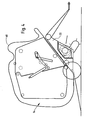
- the baling assembly 14 When new belts 48 have to be placed on the rolls 34, 38, either during initial production or for maintenance the baling assembly 14 is either swung about the axis of the bearings 52 to create a gap between the baling assembly 14 and the carrying structure 20 and the crop receiving and/or processing assembly 16 and the bale handling assembly 18 (see fig.4 ), or it is lifted completely for example by means of a fork lift or a crane, into a position as shown in figures 2 and 3 . In this situation the circumferential surfaces of the baling assembly 14, i.e. its upper, lower, front and rear sides are freely accessible.
- All rolls 34, 38 are in place except those shown in dotted lines in figure 2 and 3 , which is the most forward one 38' on the tensioning arm 40 and the upper rearward one 34' in the front part 28.
- Loops 54 of the belts 48 are created between pairs of opposite rolls 34, 38, whereas the removable rolls 34', 38' serve as idling points for these loops 54.
- the belts 48 In order to install the belts 48 they are made endless and are slid over the side structures 46 to surround the circumferential surfaces as this is shown in figure 2 .
- the missing rolls 34' and 38' are installed, which will tighten the loops 54 and apply all belts 48 to the adjacent surfaces of the rolls 34, 38.
- the tensioning means 42 is activated to provide for a tight connection.
- the situation in figure 4 is comparable to the situation in figure 2 , whereas however the distance between the baling assembly 14 and the carrying structure 20 and the crop receiving and/or processing assembly 16 and bale handling assembly 18 is much smaller and assumes a size which is needed in the case of maintenance or repair, which should be performed with the least efforts. This little distance of about 0,1 m should be sufficient to install the endless belts 48 and can be reached by either lifting off the baling assembly 14 or by pivoting it about the axis of the bearings 52.
Landscapes
- Life Sciences & Earth Sciences (AREA)
- Environmental Sciences (AREA)
- Harvesting Machines For Specific Crops (AREA)
- Storage Of Harvested Produce (AREA)
- Devices For Conveying Motion By Means Of Endless Flexible Members (AREA)
- Press Drives And Press Lines (AREA)
- Toys (AREA)
- Finger-Pressure Massage (AREA)
- Food-Manufacturing Devices (AREA)
Abstract
Description
- This invention relates to a round baler comprising a chassis and a baling assembly, whereas the baling assembly comprises side structures separated from each other, cross beams connecting the side structures, rolls rotatably journalled in these side structures and/or on a tensioning arm and belts or the like, trained over said rolls and it relates to a method to install endless belts on a round baler.
-
WO-A1-98/17097 - The same is true for a round baler disclosed in
DE-C1-40 12 755 , in which transverse struts are located such that they are located inside a space surrounded by a chain-slat conveyor. The front walls form a single unit together with the tonque and the chassis and are connected to the rear housing, such that again the chain-slat conveyor can only be installed as a string to be routed over and between the rolls, and the ends of which are connected finally to each other. - The problem this invention is based on is the impossibility to install endless belts on such type of a baler.
- This problem is solved in an innovative way by means of the teaching of claims 1 and 9, whereas advantageous features further developing the invention are given in the claims related to claim 1.
- By means of this solution the circumferential sides (front, rear, bottom, up) of the baling assembly are free and endless belts can be moved like a ring laterally over the baling assembly and than concentrated towards the bale chamber. No chassis cross beam and no tying or net wrapping assembly obstruct the path of the belt(s). At the end one or more releasably journalled rolls can be brought into their position, which apply the belts to the rolls already in place and tighten them. While it would be preferred to use belts, which are made endless from the very beginning, finite belts, the ends of which are connected can be used as well. Especially when a single and thus very heavy belt is used a mechanized installation of belts by means of a fork lift or the like is very advantageous. The side structure may be formed from side walls, i.e sheet metal surfaces or by arms, by a frame or the like as this is disclosed in
EP-A1-1 308 078 orEP-A1-1 285 571 . - Forming a baling assembly as a single and self-sufficient unit is even easier to do, if all other applying forces resulting from pulling the round baler over the field and from the weight and operation of all components are assumed by a chassis with wheels and a tongue, to which the baling assembly is connected. In such a case interfaces are provided at the chassis and the baling assembly, which easily can get separated. As another advantage various baling assemblies may get connected to such a chassis.
- All known types of crop receiving and/or processing assemblies, like pick-ups, cutting means, windrowing means, humidifying means, etc. can be attached to the carrying structure either alone or in combination with each other. Since they are not connected to the baling assembly directly, the belts can be moved like a ring over the baling assembly, once it is lifted from the chassis. Height adjustment devices, like hydraulic actuators would act between the carrying structure and the respective crop receiving and/or processing assembly to move it into one or several operative positions and into an inoperative position.
- Rather than to the baling assembly, if desired, bale handling assemblies can be attached to the carrying structure, like a bale wrapping means, a bale weighing means, a bale unloading means, a bale tying or netting means, etc., again either alone or in combination with each other. In prior art round balers such bale handling assemblies would often be attached to the baling assembly and obstruct the way of belts moved ringwise over the baling assembly.
- Since with known balers it is normally a front part, which does not need adoption to another size or type of the rear part of the baler, it reduces assembly efforts, if said front part is fixed to the carrying structure, whereas a rear part is adapted to and fixed to said front part. For example, a round baler may have a front part with different settings of rolls, to which may be attached one of a set of different rear parts, with belts on rolls with different settings. This however does not exclude, that both - the front and the rear part - are attached to the carrying structure, such that in the case of a round baler the rear part is hinged to the carrying structure rather than to the front part.
- The belts can be pressed onto the rolls and the lately installed rolls to press the belts on the rolls already in place, can be brought in place in a fixed structure of the baling assembly, if some of the rolls are replaceable while the structures are in place, in particular by means of shafts or stub shafts connectable to a roll body.
- Freeing the circumference of the baling assembly may happen by disconnecting the whole baling assembly from the carrying structure and by lifting it therefrom by means of a crane or the like. Or access can be provided, if the baling assembly is hinged to the carrying structure such, that it can be tilted laterally about an axis extending substantially in the longitudinal direction of the baler. Latter solution does not require a crane but could be performed also with a jack stand or hydraulic actuator. The baling assembly would always remain connected to the carrying structure and could easily be returned to the initial position.
- A tilting movement or even a removal of the baling assembly from the carrying structure is easy to accomplish, if the drives are easy to disconnect, like with chains, universal joint shafts, clutches etc., when disconnection is needed. Alternatively hydraulic hoses and couplings may be used. If the drives are present on the side, where the baling assembly is hinged to the carrying structure, universal joint shafts, universal joints, hydraulic or electric cables or the like may be provided, which retain the connection even in the tilted position.
- A fast way to install endless belts on a baling assembly of a round baler is seen in following method, namely a) the baling assembly is put into a position in which the rolls are radially free to the outside, b) the belt is moved as a ring over the baling assembly, c) at least one loop is formed by the belt and a roll is moved into this loop and fixed at the side structures to thereby apply the belt to the rolls and d)a tensioning device is applied to either moveable rolls and/or to a belt strand between two rolls.
- Hereto after one embodiment of the invention is described in more detail and in relation to the drawing. It is shown in:
- Fig. 1
- a baler in a schematic side view with the components disassembled,
- Fig. 2
- the baler of
figure 1 in a partly assembled stage with loose endless belts surrounding a baling assembly, - Fig. 3
- the baler of
figure 2 , whereas the belts are under tension and - Fig. 4
- the baler of
figure 2 , whereas the baling assembly is moved away from a carrying structure by a short distance. -
Figure 1 shows abaler 10, having achassis 12, abaling assembly 14, a crop receiving and/orprocessing assembly 16 and abale handling assembly 18. - The
baler 10 as shown is in the form of a round baler of the variable chamber type. Thebaler 10 is of the pull type, i.e. it gets attached to a tractor (not shown) or the like and is pulled during operation and transport. - The
chassis 12 comprises acarrying structure 20,wheels 22 and atongue 24. Thechassis 12 is of a self-carrying structure to which all assemblies of thebaler 10 can be attached. - The
carrying structure 20 is made of beams, traverses, struts, axles, cross beams, etc. welded or bolted together to form a rigid piece. Thecarrying structure 20 is formed such, that it can assume in an inner space or on its top side thebaling assembly 14, at its underside the crop receiving and/orprocessing assembly 16 and normally at the back side or above the crop receiving and/or processing assembly 16 abale handling assembly 18. Thebale handling assembly 18 could be installed on any place which fits the purpose. Flanges or other interface connecting means are provided at places which are useful to receive either of theabove assemblies carrying structure 20 extends under an angle of about 45 degrees to the ground on which it stands and is connected to thetongue 24 at one end and to thewheels 22 at the other end. Two beams (only one shown) extend on each side in the longitudinal direction of thebaler 10 and are interconnected by means of cross beams (not shown). Provided at the underside of thecarrying structure 20 is arecess 26 to provide additional space for the crop receiving and/orprocessing assembly 16. Such arecess 26 or additional space may not be needed in other embodiments. While thecarrying structure 20 here is shown in straight lines, it is obvious, that it may be of a different shape and layout, when this is necessary. Furthermore thecarrying structure 20 may be formed such, that thebaling assembly 14 is not fastened to its upper side, but is suspended from a portion high up. Thecarrying structure 20 is also provided with electronic controls (not shown) and drives 56 in the form of belts, chains, gears or hydraulic drives, whereas the one shown comprises a bevel gear with an universal joint. In a slight overlapping relationship to the wheels 22 abottom roll 58 is rotatably received by thecarrying structure 20. Thisbottom roll 58 is oriented and located such, that it can support a round bale formed in thisbaling assembly 14. - The
wheels 22 are rotatably connected to thecarrying structure 20 either directly or via an axle (not shown). Thewheels 22 may be arranged in tandem fashion, spring suspended or fixed, steerable or straight and with or without brakes. The arrangement of thewheels 22 is such, that the balingassembly 14 in question can be readily connected to the carryingstructure 20. - The
tongue 24 is connected to the front end area of the carryingstructure 20 in a vertically adjustable way. In other embodiments thetongue 24 may be attached rigidly. Sufficient space is left below thetongue 24 and the carryingstructure 20 to receive the crop receiving and/or processingassembly 16. Beyond that thetongue 24 is of known construction. - The baling
assembly 14 is formed by afront part 28 and arear part 30, which are connected to each other in abearing 32 with a pivot axis extending horizontally and transverse to the longitudinal direction of thebaler 10. The balingassembly 14 is substantially of known type and in the form of a variable chamber round baler, in which a serious ofrolls 34 is rotatably received inside structures 36 and whereasother rolls 38 are carried by atensioning arm 40 moving between end positions against the resistance provided by a tensioning means 42, like a spring or a hydraulic actuator. Ahydraulic actuator 44 is provided to swing therear part 30 about the pivot axle of thebearing 32 into an unload or baling position. This balingassembly 14 is formed as a self-carrying unit, which can be handled during assembly, transport etc. as a single and independent piece. For this purpose struts and crossbeams 46 are provided between and fixed to theside structures 30, to make the front and therear part assembly 14 is provided furthermore with a set ofbelts 48, running parallel with little distance to each other over therolls belts 48 are manufactured in an endless fashion, the ends of thebelts 48 are connected to each other to make thebelts 48 endless. In other embodiments the belts may be replaced by a chain and slat conveyor or by a single belt. When looking onfigure 1 it is visible, that the cross beams 46 are provided inside a space covered by thebelts 48 and close to a fixedroll 34, such, that even with a completed bale in abale chamber 50 thebelts 48 will not touch the cross beams 46. The location of the cross beams 46 is chosen such, that if thebelts 48 are slid over the baling assembly and are concentrated towards thebale chamber 50, they are always in the shadow of therolls 34 and are facing the inner side of thebelts 48 as opposed to their outer side. Some of the rolls 34' and 38' are either made of multiple parts with a shaft or stub shafts and a roll body, or they can be inserted through holes in one of theside structures 36. This location of thebeams 46 and the use of such rolls 34', 38' are reasons, why thebelts 48 can be installed as will be described later. The underside of thefront part 28 forms an interface to be connected to the upper side of the carryingstructure 20. In thisspecific embodiment bearings 52 are provided by means of which thefront part 28 can be secured to the carryingstructure 20 and tilted transverse to the longitudinal direction of thebaler 10. - The crop receiving and/or processing
assembly 16 is formed as a pick-up with a subsequent cutting device combined to a single unit. In other embodiments it may be either of them or another crop receiving and/or processing assembly, like a mower. Usually this crop receiving and/or processingassembly 16 extends laterally beyond the carryingstructure 20 and has a rearward delivery opening to feed the crop into thebale chamber 50. Contrary to the prior art this crop receiving and/or processingassembly 16 is not connected directly to the balingassembly 16 but to the carryingstructure 20, where it is suspended in a vertically moveable way, as this is known. Guide sheets or the like will be provided - where necessary - to provide for a secure feeding of the crop along the feed path, when the crop receiving and/or processingassembly 16 is adjusted in height. Unshown interfaces are provided at the underside of the carryingstructure 20 and on the upper side of the crop receiving and/or processingassembly 16 to connect both to each other, whereas connection may happen via fast connectors, bearings, flanges or the like. - The
bale handling assembly 18 is shown as a bale ramp, on which a bale can roll down, once therear part 30 is swung up. Instead of or in addition to it a bale wrapper, a weighing device, a bale tying or netting device or the like could be attached to the carryingstructure 20. The connection between thebale handling assembly 18 and the carryingstructure 20 may be rigid or adjustable. Thebale handling assembly 18 may include either means that is used to handle or process the bale as opposed to the crop not being formed to a bale yet. - It is obvious from the above description, that
various baling assemblies 14 and crop receiving and/orprocessing assemblies 16 and/orbale handling assembly 18 can be attached to the underside, upper side or rear side of the carryingstructure 20 respectively to form a series ofdifferent balers 10. - Reference is made to
figures 2 and3 to describe the method for installing thebelts 48. - When
new belts 48 have to be placed on therolls assembly 14 is either swung about the axis of thebearings 52 to create a gap between the balingassembly 14 and the carryingstructure 20 and the crop receiving and/or processingassembly 16 and the bale handling assembly 18 (seefig.4 ), or it is lifted completely for example by means of a fork lift or a crane, into a position as shown infigures 2 and3 . In this situation the circumferential surfaces of the balingassembly 14, i.e. its upper, lower, front and rear sides are freely accessible. All rolls 34, 38 are in place except those shown in dotted lines infigure 2 and3 , which is the most forward one 38' on thetensioning arm 40 and the upper rearward one 34' in thefront part 28.Loops 54 of thebelts 48 are created between pairs ofopposite rolls loops 54. In order to install thebelts 48 they are made endless and are slid over theside structures 46 to surround the circumferential surfaces as this is shown infigure 2 . As a next step the missing rolls 34' and 38' are installed, which will tighten theloops 54 and apply allbelts 48 to the adjacent surfaces of therolls figure 4 is comparable to the situation infigure 2 , whereas however the distance between the balingassembly 14 and the carryingstructure 20 and the crop receiving and/or processingassembly 16 andbale handling assembly 18 is much smaller and assumes a size which is needed in the case of maintenance or repair, which should be performed with the least efforts. This little distance of about 0,1 m should be sufficient to install theendless belts 48 and can be reached by either lifting off the balingassembly 14 or by pivoting it about the axis of thebearings 52.
Claims (9)
- Round baler (10), comprising a chassis (12) and a baling assembly (14), whereas the baling assembly (14) comprises side structures (36) separated from each other, cross beams (46) connecting the side structures (46), rolls (34, 38) rotatably journalled in these side structures (36) and/or on a tensioning arm (40), rolls (34', 38') releasably mountable to the side structures (36) and/or a tensioning arm (40), and belts (48) or the like, trained over said rolls (34, 34', 38, 38'), whereas the cross beams are located such, that they face an interior side of the belts (48) , characterized in that the baling assembly (14) is formed as a unit which can be fixed to and released from the chassis (12) at an interface.
- Round baler according to claim 1, characterized in that the chassis (12) is formed as a unit and contains a tongue (24), wheels (22) and a carrying structure (20).
- Round baler according to claim 1 or 2, characterized by a crop receiving and/or processing assembly (16), which is formed as a unit connectible to the chassis (12) and which comprises a pick-up and/or a cutting means and/or a windrowing means and/or a humidifying means.
- Round baler according to any of the preceding claims, characterized by a bale handling assembly (18) which is connectible to the chassis (12) and which comprises a bale wrapping means and/or a bale weighing means and/or a bale unloading means and/or a bale tying or netting means.
- Round baler according to one or more of the previous claims, characterized in that the baling assembly (14) has a front part. (28) with an interface to be coupled to the chassis (12).
- Round baler according to one or more of the previous claims, characterized in that the releasably mountable rolls (34', 38') are replaceable while the side structures (36) are in place, and in particular contain shafts or stub shafts connectible to a roll body.
- Round baler according to one or more of the previous claims, characterized in that the baling assembly (14) is hinged to the carrying structure (20) such, that it can be tilted laterally about an axis extending substantially in the longitudinal direction of the baler (10).
- Round baler according to one or more of the previous claims, characterized in that the drive (56) of the baling assembly (14) is either flexible to allow said tilting movement, or has means for disconnection.
- Method of installing at least one endless belt (48) on a serious of rolls (34, 38) extending between the side structures (36) of a baling assembly (14) of a round baler, characterized in that:a) the baling assembly (14) is put into a position in which the rolls (34, 38) are radially free to the outside;b) the belt (48) is moved like a ring over the baling assembly (14);c) at least one loop (54) is formed by the belt (48) and a roll (34', 38') is moved into this loop (54) and fixed at the side structures (36) to thereby apply the belt (48) to the rolls (34, 38);d) a tensioning means (42) is applied to either moveable rolls (38) and/or to a belt strand between two rolls (34, 38).
Priority Applications (5)
| Application Number | Priority Date | Filing Date | Title |
|---|---|---|---|
| AT04001653T ATE460835T1 (en) | 2004-01-27 | 2004-01-27 | ROUND BALE PRESS |
| EP04001653A EP1559308B1 (en) | 2004-01-27 | 2004-01-27 | Round baler |
| DE602004026027T DE602004026027D1 (en) | 2004-01-27 | 2004-01-27 | Round baler |
| US11/032,622 US7111548B2 (en) | 2004-01-27 | 2005-01-10 | Round baler arranged to facilitate the installation of endless baling elements |
| US11/501,270 US7331280B2 (en) | 2004-01-27 | 2006-08-09 | Round baler arranged to facilitate the installation of endless baling elements |
Applications Claiming Priority (1)
| Application Number | Priority Date | Filing Date | Title |
|---|---|---|---|
| EP04001653A EP1559308B1 (en) | 2004-01-27 | 2004-01-27 | Round baler |
Publications (2)
| Publication Number | Publication Date |
|---|---|
| EP1559308A1 EP1559308A1 (en) | 2005-08-03 |
| EP1559308B1 true EP1559308B1 (en) | 2010-03-17 |
Family
ID=34639375
Family Applications (1)
| Application Number | Title | Priority Date | Filing Date |
|---|---|---|---|
| EP04001653A Expired - Lifetime EP1559308B1 (en) | 2004-01-27 | 2004-01-27 | Round baler |
Country Status (4)
| Country | Link |
|---|---|
| US (2) | US7111548B2 (en) |
| EP (1) | EP1559308B1 (en) |
| AT (1) | ATE460835T1 (en) |
| DE (1) | DE602004026027D1 (en) |
Families Citing this family (3)
| Publication number | Priority date | Publication date | Assignee | Title |
|---|---|---|---|---|
| US8250759B2 (en) * | 2008-02-07 | 2012-08-28 | Deese Kenneth A | Rotor hub maintenance system |
| US10028445B2 (en) * | 2012-04-20 | 2018-07-24 | Forage Company B.V. | Continuous bale forming apparatus with a reciprocating bale pushing device |
| US9084394B2 (en) | 2013-02-22 | 2015-07-21 | CNH Industrial Canada, LTD | Continuous crop accumulator for agricultural harvesters |
Family Cites Families (13)
| Publication number | Priority date | Publication date | Assignee | Title |
|---|---|---|---|---|
| US4088069A (en) * | 1976-06-08 | 1978-05-09 | Deere & Company | Elastic bale-forming conveyor for cylindrical bales |
| US4072095A (en) * | 1976-08-30 | 1978-02-07 | Sperry Rand Corporation | Twine wrapping mechanism for a roll forming machine |
| US4135352A (en) * | 1976-12-07 | 1979-01-23 | Hesston Corporation | Semicontinuous large round baling machine |
| US4339907A (en) * | 1980-11-24 | 1982-07-20 | Kopaska Arnold F | Endless belt changing in a rotary crop baler |
| GB2196294B (en) * | 1986-10-20 | 1991-01-23 | Deere & Co | Machine for forming cylindrical bales of crop |
| DE4012755C1 (en) * | 1990-04-21 | 1991-10-10 | Maschinenfabriken Bernard Krone Gmbh, 4441 Spelle, De | Hay, straw, grass, etc., bailing press - has inner tensile guide rollers movable into raised, specified guide position |
| US5333516A (en) * | 1991-05-28 | 1994-08-02 | Vermeer Manufacturing Company | Apparatus for driving transverse shafts of a baler |
| US5488883A (en) * | 1992-12-18 | 1996-02-06 | Vermeer Manufacturing Company | Direct drive system for a baler |
| US5819515A (en) | 1996-10-18 | 1998-10-13 | Hay & Forage Industries | Eased inlet tailgate roll arrangement for variable chamber round baler |
| GB9826678D0 (en) * | 1998-12-04 | 1999-01-27 | Kverneland Naerbo As | Combined baler/bale wrapper apparatus |
| DE10021352A1 (en) * | 2000-05-02 | 2001-11-08 | Lely Welger Maschinenfabrik Gm | Round baler for agricultural stalks |
| DE60128563T2 (en) | 2001-08-10 | 2008-01-31 | Deere & Company, Moline | Wrapping system for a round baler |
| DE10153539A1 (en) | 2001-10-30 | 2003-05-28 | Deere & Co | Round baler |
-
2004
- 2004-01-27 EP EP04001653A patent/EP1559308B1/en not_active Expired - Lifetime
- 2004-01-27 DE DE602004026027T patent/DE602004026027D1/en not_active Expired - Lifetime
- 2004-01-27 AT AT04001653T patent/ATE460835T1/en not_active IP Right Cessation
-
2005
- 2005-01-10 US US11/032,622 patent/US7111548B2/en not_active Expired - Lifetime
-
2006
- 2006-08-09 US US11/501,270 patent/US7331280B2/en not_active Expired - Lifetime
Also Published As
| Publication number | Publication date |
|---|---|
| ATE460835T1 (en) | 2010-04-15 |
| DE602004026027D1 (en) | 2010-04-29 |
| US20060266231A1 (en) | 2006-11-30 |
| US7111548B2 (en) | 2006-09-26 |
| EP1559308A1 (en) | 2005-08-03 |
| US7331280B2 (en) | 2008-02-19 |
| US20050160922A1 (en) | 2005-07-28 |
Similar Documents
| Publication | Publication Date | Title |
|---|---|---|
| US4687402A (en) | Carrier for cylindrical hay bales | |
| US6640699B2 (en) | Round baler bale chamber having simplified discharge arrangement | |
| CA2441236C (en) | Wrapping implement | |
| US6901719B2 (en) | Combination of a large round baler and wrapping implement | |
| CA1068909A (en) | Header suspension and lift means | |
| US6463714B2 (en) | Integrated baler and bale wrapping device | |
| JPS6015285B2 (en) | bale forming machine | |
| AU2019204767B2 (en) | Improvements in and relating to Bale Wrapping Machines | |
| EP1559309B1 (en) | Baler | |
| CA2357294C (en) | Combination of a baler and wrapping apparatus, and a chassis to accommodate them | |
| EP1559308B1 (en) | Round baler | |
| US3951288A (en) | Large round bale handling apparatus | |
| US5639198A (en) | Hay bale loader | |
| US4434607A (en) | Overfill protection apparatus for roll baling machine | |
| US2836022A (en) | Specific drive and mounting means for a forage harvester | |
| US9066471B1 (en) | Apparatus and method for a baler cart | |
| GB2257415A (en) | Bale carrying attachment for a vehicle. | |
| US1911637A (en) | Harvesting machine | |
| NZ243169A (en) | Towed round hay bale loader and transporter with transverse tined conveyor for feeding out hay | |
| JPS6343056B2 (en) | ||
| NZ727463B2 (en) | Improvements in and relating to bale wrapping machines |
Legal Events
| Date | Code | Title | Description |
|---|---|---|---|
| PUAI | Public reference made under article 153(3) epc to a published international application that has entered the european phase |
Free format text: ORIGINAL CODE: 0009012 |
|
| AK | Designated contracting states |
Kind code of ref document: A1 Designated state(s): AT BE BG CH CY CZ DE DK EE ES FI FR GB GR HU IE IT LI LU MC NL PT RO SE SI SK TR |
|
| AX | Request for extension of the european patent |
Extension state: AL LT LV MK |
|
| 17P | Request for examination filed |
Effective date: 20060203 |
|
| AKX | Designation fees paid |
Designated state(s): AT BE BG CH CY CZ DE DK EE ES FI FR GB GR HU IE IT LI LU MC NL PT RO SE SI SK TR |
|
| 17Q | First examination report despatched |
Effective date: 20060428 |
|
| GRAP | Despatch of communication of intention to grant a patent |
Free format text: ORIGINAL CODE: EPIDOSNIGR1 |
|
| GRAS | Grant fee paid |
Free format text: ORIGINAL CODE: EPIDOSNIGR3 |
|
| GRAA | (expected) grant |
Free format text: ORIGINAL CODE: 0009210 |
|
| AK | Designated contracting states |
Kind code of ref document: B1 Designated state(s): AT BE BG CH CY CZ DE DK EE ES FI FR GB GR HU IE IT LI LU MC NL PT RO SE SI SK TR |
|
| REG | Reference to a national code |
Ref country code: GB Ref legal event code: FG4D |
|
| REG | Reference to a national code |
Ref country code: CH Ref legal event code: EP |
|
| REG | Reference to a national code |
Ref country code: IE Ref legal event code: FG4D |
|
| REF | Corresponds to: |
Ref document number: 602004026027 Country of ref document: DE Date of ref document: 20100429 Kind code of ref document: P |
|
| REG | Reference to a national code |
Ref country code: NL Ref legal event code: VDEP Effective date: 20100317 |
|
| PG25 | Lapsed in a contracting state [announced via postgrant information from national office to epo] |
Ref country code: FI Free format text: LAPSE BECAUSE OF FAILURE TO SUBMIT A TRANSLATION OF THE DESCRIPTION OR TO PAY THE FEE WITHIN THE PRESCRIBED TIME-LIMIT Effective date: 20100317 Ref country code: SI Free format text: LAPSE BECAUSE OF FAILURE TO SUBMIT A TRANSLATION OF THE DESCRIPTION OR TO PAY THE FEE WITHIN THE PRESCRIBED TIME-LIMIT Effective date: 20100317 Ref country code: AT Free format text: LAPSE BECAUSE OF FAILURE TO SUBMIT A TRANSLATION OF THE DESCRIPTION OR TO PAY THE FEE WITHIN THE PRESCRIBED TIME-LIMIT Effective date: 20100317 |
|
| PG25 | Lapsed in a contracting state [announced via postgrant information from national office to epo] |
Ref country code: RO Free format text: LAPSE BECAUSE OF FAILURE TO SUBMIT A TRANSLATION OF THE DESCRIPTION OR TO PAY THE FEE WITHIN THE PRESCRIBED TIME-LIMIT Effective date: 20100317 Ref country code: BE Free format text: LAPSE BECAUSE OF FAILURE TO SUBMIT A TRANSLATION OF THE DESCRIPTION OR TO PAY THE FEE WITHIN THE PRESCRIBED TIME-LIMIT Effective date: 20100317 Ref country code: CY Free format text: LAPSE BECAUSE OF FAILURE TO SUBMIT A TRANSLATION OF THE DESCRIPTION OR TO PAY THE FEE WITHIN THE PRESCRIBED TIME-LIMIT Effective date: 20100317 Ref country code: EE Free format text: LAPSE BECAUSE OF FAILURE TO SUBMIT A TRANSLATION OF THE DESCRIPTION OR TO PAY THE FEE WITHIN THE PRESCRIBED TIME-LIMIT Effective date: 20100317 Ref country code: ES Free format text: LAPSE BECAUSE OF FAILURE TO SUBMIT A TRANSLATION OF THE DESCRIPTION OR TO PAY THE FEE WITHIN THE PRESCRIBED TIME-LIMIT Effective date: 20100628 Ref country code: GR Free format text: LAPSE BECAUSE OF FAILURE TO SUBMIT A TRANSLATION OF THE DESCRIPTION OR TO PAY THE FEE WITHIN THE PRESCRIBED TIME-LIMIT Effective date: 20100618 Ref country code: NL Free format text: LAPSE BECAUSE OF FAILURE TO SUBMIT A TRANSLATION OF THE DESCRIPTION OR TO PAY THE FEE WITHIN THE PRESCRIBED TIME-LIMIT Effective date: 20100317 Ref country code: SE Free format text: LAPSE BECAUSE OF FAILURE TO SUBMIT A TRANSLATION OF THE DESCRIPTION OR TO PAY THE FEE WITHIN THE PRESCRIBED TIME-LIMIT Effective date: 20100317 |
|
| PG25 | Lapsed in a contracting state [announced via postgrant information from national office to epo] |
Ref country code: SK Free format text: LAPSE BECAUSE OF FAILURE TO SUBMIT A TRANSLATION OF THE DESCRIPTION OR TO PAY THE FEE WITHIN THE PRESCRIBED TIME-LIMIT Effective date: 20100317 Ref country code: BG Free format text: LAPSE BECAUSE OF FAILURE TO SUBMIT A TRANSLATION OF THE DESCRIPTION OR TO PAY THE FEE WITHIN THE PRESCRIBED TIME-LIMIT Effective date: 20100617 Ref country code: CZ Free format text: LAPSE BECAUSE OF FAILURE TO SUBMIT A TRANSLATION OF THE DESCRIPTION OR TO PAY THE FEE WITHIN THE PRESCRIBED TIME-LIMIT Effective date: 20100317 |
|
| PLBE | No opposition filed within time limit |
Free format text: ORIGINAL CODE: 0009261 |
|
| STAA | Information on the status of an ep patent application or granted ep patent |
Free format text: STATUS: NO OPPOSITION FILED WITHIN TIME LIMIT |
|
| PG25 | Lapsed in a contracting state [announced via postgrant information from national office to epo] |
Ref country code: DK Free format text: LAPSE BECAUSE OF FAILURE TO SUBMIT A TRANSLATION OF THE DESCRIPTION OR TO PAY THE FEE WITHIN THE PRESCRIBED TIME-LIMIT Effective date: 20100317 Ref country code: PT Free format text: LAPSE BECAUSE OF FAILURE TO SUBMIT A TRANSLATION OF THE DESCRIPTION OR TO PAY THE FEE WITHIN THE PRESCRIBED TIME-LIMIT Effective date: 20100719 |
|
| 26N | No opposition filed |
Effective date: 20101220 |
|
| PG25 | Lapsed in a contracting state [announced via postgrant information from national office to epo] |
Ref country code: IT Free format text: LAPSE BECAUSE OF FAILURE TO SUBMIT A TRANSLATION OF THE DESCRIPTION OR TO PAY THE FEE WITHIN THE PRESCRIBED TIME-LIMIT Effective date: 20100317 |
|
| PG25 | Lapsed in a contracting state [announced via postgrant information from national office to epo] |
Ref country code: MC Free format text: LAPSE BECAUSE OF NON-PAYMENT OF DUE FEES Effective date: 20110131 |
|
| REG | Reference to a national code |
Ref country code: CH Ref legal event code: PL |
|
| PG25 | Lapsed in a contracting state [announced via postgrant information from national office to epo] |
Ref country code: CH Free format text: LAPSE BECAUSE OF NON-PAYMENT OF DUE FEES Effective date: 20110131 Ref country code: LI Free format text: LAPSE BECAUSE OF NON-PAYMENT OF DUE FEES Effective date: 20110131 |
|
| PG25 | Lapsed in a contracting state [announced via postgrant information from national office to epo] |
Ref country code: LU Free format text: LAPSE BECAUSE OF NON-PAYMENT OF DUE FEES Effective date: 20110127 |
|
| PG25 | Lapsed in a contracting state [announced via postgrant information from national office to epo] |
Ref country code: TR Free format text: LAPSE BECAUSE OF FAILURE TO SUBMIT A TRANSLATION OF THE DESCRIPTION OR TO PAY THE FEE WITHIN THE PRESCRIBED TIME-LIMIT Effective date: 20100317 |
|
| PG25 | Lapsed in a contracting state [announced via postgrant information from national office to epo] |
Ref country code: HU Free format text: LAPSE BECAUSE OF FAILURE TO SUBMIT A TRANSLATION OF THE DESCRIPTION OR TO PAY THE FEE WITHIN THE PRESCRIBED TIME-LIMIT Effective date: 20100317 |
|
| PGFP | Annual fee paid to national office [announced via postgrant information from national office to epo] |
Ref country code: GB Payment date: 20140127 Year of fee payment: 11 |
|
| GBPC | Gb: european patent ceased through non-payment of renewal fee |
Effective date: 20150127 |
|
| PG25 | Lapsed in a contracting state [announced via postgrant information from national office to epo] |
Ref country code: GB Free format text: LAPSE BECAUSE OF NON-PAYMENT OF DUE FEES Effective date: 20150127 |
|
| REG | Reference to a national code |
Ref country code: FR Ref legal event code: PLFP Year of fee payment: 13 |
|
| REG | Reference to a national code |
Ref country code: FR Ref legal event code: PLFP Year of fee payment: 14 |
|
| REG | Reference to a national code |
Ref country code: FR Ref legal event code: PLFP Year of fee payment: 15 |
|
| PGFP | Annual fee paid to national office [announced via postgrant information from national office to epo] |
Ref country code: IE Payment date: 20230127 Year of fee payment: 20 Ref country code: FR Payment date: 20230125 Year of fee payment: 20 |
|
| PGFP | Annual fee paid to national office [announced via postgrant information from national office to epo] |
Ref country code: DE Payment date: 20221221 Year of fee payment: 20 |
|
| REG | Reference to a national code |
Ref country code: DE Ref legal event code: R071 Ref document number: 602004026027 Country of ref document: DE |
|
| REG | Reference to a national code |
Ref country code: IE Ref legal event code: MK9A |
|
| PG25 | Lapsed in a contracting state [announced via postgrant information from national office to epo] |
Ref country code: IE Free format text: LAPSE BECAUSE OF EXPIRATION OF PROTECTION Effective date: 20240127 |
|
| PG25 | Lapsed in a contracting state [announced via postgrant information from national office to epo] |
Ref country code: IE Free format text: LAPSE BECAUSE OF EXPIRATION OF PROTECTION Effective date: 20240127 |