EP1559192B1 - Verfahren und einrichtung zum trainieren einer hf-verstärkerlinearisierungseinrichtung und mobiles endgerät damit - Google Patents
Verfahren und einrichtung zum trainieren einer hf-verstärkerlinearisierungseinrichtung und mobiles endgerät damit Download PDFInfo
- Publication number
- EP1559192B1 EP1559192B1 EP03786000A EP03786000A EP1559192B1 EP 1559192 B1 EP1559192 B1 EP 1559192B1 EP 03786000 A EP03786000 A EP 03786000A EP 03786000 A EP03786000 A EP 03786000A EP 1559192 B1 EP1559192 B1 EP 1559192B1
- Authority
- EP
- European Patent Office
- Prior art keywords
- sequence
- symbols
- linearization
- training sequence
- transmitted
- Prior art date
- Legal status (The legal status is an assumption and is not a legal conclusion. Google has not performed a legal analysis and makes no representation as to the accuracy of the status listed.)
- Expired - Lifetime
Links
- 238000000034 method Methods 0.000 title claims abstract description 28
- 230000005540 biological transmission Effects 0.000 claims abstract description 27
- 230000008859 change Effects 0.000 claims description 15
- 230000006854 communication Effects 0.000 abstract description 11
- 108091006146 Channels Proteins 0.000 description 26
- 238000010586 diagram Methods 0.000 description 8
- 230000011664 signaling Effects 0.000 description 6
- 230000003044 adaptive effect Effects 0.000 description 4
- 230000008901 benefit Effects 0.000 description 4
- 239000002674 ointment Substances 0.000 description 4
- 230000006978 adaptation Effects 0.000 description 2
- 238000006243 chemical reaction Methods 0.000 description 2
- 230000006870 function Effects 0.000 description 2
- 230000003595 spectral effect Effects 0.000 description 2
- 108010076504 Protein Sorting Signals Proteins 0.000 description 1
- 230000007175 bidirectional communication Effects 0.000 description 1
- 230000001627 detrimental effect Effects 0.000 description 1
- 238000002955 isolation Methods 0.000 description 1
- 230000008569 process Effects 0.000 description 1
- 230000000630 rising effect Effects 0.000 description 1
- 238000001228 spectrum Methods 0.000 description 1
Images

Classifications
-
- H—ELECTRICITY
- H04—ELECTRIC COMMUNICATION TECHNIQUE
- H04W—WIRELESS COMMUNICATION NETWORKS
- H04W52/00—Power management, e.g. Transmission Power Control [TPC] or power classes
- H04W52/04—Transmission power control [TPC]
- H04W52/52—Transmission power control [TPC] using AGC [Automatic Gain Control] circuits or amplifiers
-
- H—ELECTRICITY
- H03—ELECTRONIC CIRCUITRY
- H03F—AMPLIFIERS
- H03F1/00—Details of amplifiers with only discharge tubes, only semiconductor devices or only unspecified devices as amplifying elements
- H03F1/32—Modifications of amplifiers to reduce non-linear distortion
- H03F1/3241—Modifications of amplifiers to reduce non-linear distortion using predistortion circuits
- H03F1/3247—Modifications of amplifiers to reduce non-linear distortion using predistortion circuits using feedback acting on predistortion circuits
Definitions
- the present invention relates to the linearization of radio frequency (RF) power amplifiers. It finds applications, in particular, in RF transmitters of mobile terminals of digital radio systems. It can also be applied in the RF transmitters of the base stations in particular during the first start of such a station.
- RF radio frequency
- the modulations used for a few years comprise a phase or frequency modulation component and an amplitude modulation component.
- radio channels coexist in a given frequency band allocated to the system.
- Each radio channel is subdivided into logical channels by time division. In each time slot ("Time Slot” in English), it is emitted a group of symbols called burst or packet ("Burst" in English).
- the power level emitted in each radio channel does not interfere with communications in an adjacent radio channel.
- the RF transmitter must have a characteristic of the output power as a function of the input power, which is linear.
- the radiofrequency power amplifier (hereinafter RF amplifier) present in the RF transmitter has a linear characteristic with low output power but non-linear as soon as the power exceeds a certain threshold.
- RF amplifier radiofrequency power amplifier
- the efficiency of the RF amplifier is all the better that we work in an area near saturation that is to say in nonlinear regime.
- linearization techniques Two of the most commonly used techniques are baseband adaptive predistortion and baseband Cartesian loop.
- the signal to be transmitted is generated in I and Q format baseband. Furthermore, a coupler followed by a demodulator makes it possible to take a portion of the transmitted RF signal and to transpose it into a band. This baseband signal is compared to the baseband signal to be transmitted. An error signal resulting from this comparison attacks a modulator, which transposes to the radio frequency domain (up-conversion). The output signal of the modulator is amplified by an RF amplifier which delivers the transmitted RF signal.
- the signal to be transmitted is generated in baseband, in I and Q format, and pre-distorted via a predistortion device. Then, this signal is transposed to the RF domain through an RF modulator. Then, it is amplified in an RF amplifier. A coupler followed by an RF demodulator is used to take a portion of the transmitted RF signal and to transpose it into baseband, in I, Q format. This demodulated baseband signal is digitized and compared with the baseband signal. to emit.
- An adaptation of the predistortion coefficients, performed during a learning phase of the predistortion device makes it possible to converge the demodulated I and Q signal to the I and Q format signal to be transmitted.
- the learning method disclosed in the document WO 94/10765 thus relies on the issuance by the transmitters of the system of particular sequences, called linearization training sequences, during linearization learning phases. More particularly, training sequences are transmitted in isolation in time intervals forming a particular logical channel of the radio channels, which is dedicated solely to linearization.
- this method has several disadvantages. First of all, it requires a prior synchronization of all the emitters so that they emit their respective linearization training sequence in the logical channel dedicated to the linearization. Moreover, no data transmission can take place in the time slots of this logical channel.
- the transmitter is obliged to wait for the next time slot of the logical channel dedicated to the linearization, unless the system is considerably more complex. This is why the time spacing between two time slots of said logical channel can not exceed the second, in order to guarantee a certain quality of service (QoS). This technique is therefore very detrimental to the spectral efficiency of the radiocommunication system.
- QoS quality of service
- radio communication systems exist whose frame structure is not adapted to the transmission of a learning sequence, for example when no specific time slot has been provided for this purpose during the definition of the frame structure.
- step b) the linearization training sequence is included in a sequence of symbols furthermore provided to allow the setting of parameters of the transmission chain between said first equipment and a second equipment of the radio communication system with which said first equipment communicates.
- transmission chain is meant all the components that take part in bidirectional communication between a first and a second device, typically a mobile terminal and the base station with which it communicates.
- the sequence of symbols provided to allow the setting of parameters is a sequence of symbols provided to allow the dynamic control of the gain of a variable gain amplifier of a radio frequency receiver of a second equipment of the radio communication system with which the first equipment communicates.
- the training sequence is transmitted in step b) within a reserved time interval in the frame structure for the transmission of an AGC (Automatic Gain Control) sequence, and it ensures at the same time the role of such a sequence of AGC.
- AGC Automatic Gain Control
- the transmission time of a sequence of symbols necessary for other purposes in this case an AGC sequence transmitted to enable the dynamic control of the power of the transmitter, is used. transmitting the mobile terminal in reception.
- the value of the symbols of the AGC sequence is not subject to any constraints (the AGC sequence must simply be known from the fixed network). There is therefore complete freedom to choose the symbols of the sequence, or at least part of the symbols of the sequence, so that these symbols form a satisfactory learning sequence.
- the recurrence of the AGC sequence is adapted to the needs of the training of the linearization device of the RF amplifier.
- the AGC sequence is generally transmitted at the beginning of the frame, then during a change of logical channel, during an RF frequency change and / or during a change in the power level. Now it is substantially at these times as well that the linearization learning sequence needs to be emitted.
- the linearization training sequence is included in a sequence of symbols further provided to allow the setting of parameters of the transmission chain between said first equipment and a second equipment of the radio system with which said first equipment communicates.
- the sequence of symbols provided to allow the setting of parameters is a sequence of symbols provided to allow the dynamic control of the gain of a variable gain amplifier of a radio frequency receiver of a second equipment of the radio communication system with which the first equipment communicates.
- said means for transmitting are adapted to transmit the training sequence within a reserved time slot in the frame structure for the transmission of a CAG sequence, and the training sequence ensures at the same time the role of such a sequence of AGC.
- a third aspect of the invention relates to a mobile terminal of a radio communication system, comprising a radiofrequency transmitter having a radio frequency amplifier and a device for linearizing the radio frequency amplifier, which further comprises a device for training the linearization device. according to the second aspect.
- a fourth aspect of the invention relates to a base station of a radio communication system, comprising a radiofrequency transmitter having a radio frequency amplifier and a device for linearizing the radio frequency amplifier, which further comprises a device for learning the radio frequency device. linearization according to the third aspect.
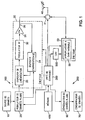
- FIG. 1 there is shown schematically the means of an exemplary mobile terminal according to the invention.
- a mobile terminal belongs for example to a radio system which furthermore comprises a fixed network having base stations.
- the terminal comprises a transmission chain 100, a reception chain 200, a control unit 300, as well as a permanent memory 400, as well as a device 500 for automatic gain control (AGC) associated with an RF receiver of the reception chain 200.
- AGC automatic gain control
- the transmission chain 100 comprises a useful data source 10, for example a speech coder delivering voice coding data.
- the source 10 is coupled to an M-ary data modulator 20 which provides the baseband modulation of the data to be transmitted according to a modulation with M distinct states, where M is a determined integer.
- the binary data it receives from the source 10 are translated by the modulator 20 into symbols belonging to an M-ary alphabet, that is to say comprising M distinct symbols.
- the output of the modulator 20 is coupled to the input of a radiofrequency transmitter 30. From the sequence of received symbols, the transmitter 30 produces an RF signal suitable for radio transmission via an antenna or cable.
- the output of the transmitter 30 is coupled to an antenna transmission / reception 40 via a switch 41. Thus the RF signal produced by the transmitter is transmitted on the radio channel associated with the transmitter.
- the reception chain 200 comprises a radio frequency receiver 50 which is coupled to the antenna 40 via the switch 41, to receive an RF signal.
- the receiver 50 transposes the RF domain to the baseband (downconversion).
- the reception channel 200 also comprises an M-ary data demodulator 60, coupled to the receiver 50.
- the data demodulator 60 provides in baseband the demodulation of the data of the received signal, that is to say the inverse operation of that provided by the modulator 20.
- the reception chain 200 comprises a data consumer device 70, such as a speech decoder, which is coupled to the demodulator 60. This device receives as input the binary data delivered by the demodulator 60 .
- the unit 300 is for example a microprocessor or a microcontroller which manages the mobile terminal. In particular, it controls the data modulator 20, the data demodulator 60, the transmitter 30 and the switch 41. It also generates signaling data that is provided to the modulator 20 to be transmitted in appropriate logical signaling channels. In contrast, the unit 300 receives from the data demodulator 60 signaling data sent by the fixed network in appropriate logical signaling channels, including timing information and operation commands.
- the memory 400 is for example a ROM ("Read Only Memory”), EPROM ("Electrically Programable ROM”) or Flash-EPROM, in which are stored data that are used for the operation of the mobile terminal. These data include a linearization training sequence to which we will return later.
- the transmitter 30 comprises a radiofrequency power amplifier 31, a radiofrequency modulator 32 which transposes the baseband to the radiofrequency domain ( conversion rising), a linearization device 33, a learning module 34 associated with the linearization device.
- the output of the power amplifier 31 delivers the RF signal to be transmitted. This is why it is coupled to the antenna 40 via the switch 41.
- the input of the power amplifier 31 receives a radio frequency signal delivered by the output of the radiofrequency modulator 32.
- the input thereof is coupled to the output of the data modulator 20 to receive the sequence of symbols forming the baseband signal to be transmitted, through the linearization device 33.
- the latter comprises for example a predistortion device comprising a palette ("look-up table" in English) which translates each value of the signal to be transmitted into a pre-distorted value.
- the device 33 may also include means for controlling the amplitude of the signal at the output of the transmitter 30.
- the learning module 34 carries out the training of the linearization device 33 as a function of an input signal which reflects the RF signal delivered by the output of the power amplifier 31. For this purpose, the module 34 receives a part of this RF signal, which is taken at the output of the power amplifier 31 by means of a coupler 36. As needed, the module 34 provides the baseband return of the RF signal thus taken. Although being entirely represented inside the transmitter 30, the module 34 may, at least in part, be implemented by means belonging to the control unit 300, in particular software means.
- the automatic gain control device 500 allows the control unit 300 to dynamically vary the gain of the variable gain amplifier 59 of the RF receiver 50, based on information received from the base station. with which the terminal communicates, according to a method known in itself. Under this method, the base station transmits at specific times a specific sequence, called AGC sequence. This sequence is known and recognizable by the mobile terminal. It allows it to measure the power of the signal received from the base station and to deduce a gain control of the amplifier 59. This method is implemented in the mobile terminal by the device 500 under the control of the unit 300.
- the learning method of the device 33 comprises a step of generating a training sequence having a determined number N of symbols, where N is an integer. This step is performed by the data modulator 20 under the control of the control unit 300. For this purpose, the unit 300 reads a corresponding bit sequence in the memory 400.
- the training sequence is transmitted by means of the transmitter 30 in at least some of the bursts emitted by it, according to the frame structure of the system.
- the learning device 34 then obtains the transmitted learning sequence and compares it with the generated training sequence, and consequently performs actions such as predistortion coefficient adaptations or the like of the linearization device 33, according to an algorithm determined learning.
- This algorithm can be adaptive. We are talking about training to designate these operations.
- N is 10.
- the AGC sequence comprises at least N symbols. It can therefore have a length greater than that of the training sequence, when it comprises more than N symbols.
- the symbols of the training sequence are preferably the symbols of the AGC sequence that are transmitted first. In this way, the convergence of the learning algorithm and thus the linearization of the RF amplifier are obtained as quickly as possible.
- Learning phases can be performed periodically or otherwise. Other constraints may have to be taken into account after the initial learning phase, when it is appropriate to correct drifts of the transmitter.
- the learning sequence can therefore evolve in both content and length.
- the number N is not necessarily fixed from one transmission of the training sequence to another. If an increase in the size of the sequence poses problems (for example if the frame structure is not very flexible), one can fix the size N of the sequence and just modify its contents according to the evolution of the constraints on the system .
- the diagram of Figure 2 illustrates a first example of a burst, which does not include a sequence of AGC.
- the burst has a duration equal to 20 ms. It firstly comprises a ramp ramp 51 ("ramping-up" in English) of 625 ⁇ s, comprising five stuffing symbols, to ensure the ramp up.
- stuffing symbols it is meant that the binary data transmitted in this rise ramp are stuffing bits, that is to say, for example, a sequence of 0.
- a synchronization data sequence 52 whose duration is equal to about 5 ms. Then, it comprises a sequence of useful data 53.
- the useful data may be data encoding the voice and more generally traffic data, or signaling data depending on whether the burst is transmitted on a logical traffic channel or a channel signaling logic, respectively.
- it includes a down ramp 54, again having five stuffing symbols for descent.
- a guard time is further provided after the issuance of a salvo, to ensure the return to the reception of the transmitter.
- any frame structure it is expected to emit isolated bursts, in particular at each change of logical channel (occurring in particular at each turnaround, that is to say passage from a reception phase to a phase transmission of the terminal), at each RF frequency change (when a frequency hopping functionality is implemented by the system), at each transmission power step change, or in other special cases that it would be too long to detail here.
- FIG. 3 shows an example of such an isolated frame comprising, before the synchronization sequence 52, an AGC sequence referenced 55.
- This sequence 55 is emitted to allow the dynamic control, by the fixed network, of the transmission power of the transmitter. transmitter (see above).
- the sequence 52 and the sequence 55 only last from 1 to 3 ms each.
- the other parts of the burst are unchanged with respect to the burst of FIG. 2.
- the payload sequence 53 may however be shorter than in the case of a normal burst according to FIG.
- a portion of these isolated bursts is used to enable the training device 34 of the radiofrequency transmitter 32 to execute a training algorithm of the linearization device 33.
- linearization is thus included in the aforementioned AGC sequence.
- the AGC sequence, and therefore the training sequence are preferably transmitted at the beginning of the frame, then during a logical channel change, during an RF frequency change and / or during a step changeover. of power and / or in other cases that it would be too long to detail here. This is why it is particularly advantageous to combine these sequences (the training sequence being included in the AGC sequence).
- the AGC sequence is located as close as possible to the signal ramp, for example, just following this ramp. In this way, the linearization device can be learned as quickly as possible and thus disturb transmission as little as possible.
- the length of the training sequence is such that it does not occupy too much of the burst in order to keep a maximum of symbols for the dissemination of useful information.
- This duration obviously depends on the precision sought for the learning algorithm but a compromise between accuracy and duration is often necessary in order to keep a maximum of useful information in the salvo. A reasonable compromise is reached when it represents about 5% of the total duration of the salvo.
- FIG. 4 illustrates the implementation of an AGC method (known per se) between a first equipment 5 and a second equipment 5 'of a radiocommunications system.
- the equipment 5 is here a mobile terminal for example as described above with reference to Figure 1. It comprises the RF transmitter 30 and the RF receiver 50, the latter comprising the variable gain amplifier 59.
- the equipment 5 ' here is a base station with which the mobile terminal 5 communicates, which comprises an RF transmitter 30' and an RF receiver 50 'having a variable gain amplifier 59'.
- the components 30 ', 50' and 59 'of the base station 5' are identical or comparable to the components 30, 50 and 59 respectively of the mobile terminal 5 '. These components are not detailed again here.
- An AGC sequence transmitted by the mobile terminal 5 allows the dynamic control of the gain of the amplifier 59 'of the receiver 50' of the base station 5 '. Conversely, an AGC sequence transmitted by the base station 5 'allows the dynamic control of the gain of the amplifier 59 of the receiver 50 of the mobile terminal.
Landscapes
- Engineering & Computer Science (AREA)
- Physics & Mathematics (AREA)
- Nonlinear Science (AREA)
- Power Engineering (AREA)
- Computer Networks & Wireless Communication (AREA)
- Signal Processing (AREA)
- Mobile Radio Communication Systems (AREA)
- Transmitters (AREA)
- Amplifiers (AREA)
- Cable Transmission Systems, Equalization Of Radio And Reduction Of Echo (AREA)
- Digital Transmission Methods That Use Modulated Carrier Waves (AREA)
Claims (16)
- Verfahren zum Trainieren einer Vorrichtung zur Linearisierung eines Funkfrequenzverstärkers (31), der in einem Funkfrequenzsender (30) einer ersten Einrichtung (5) eines Funkkommunikationssystems vorgesehen ist, wobei dieser Sender dafür ausgelegt ist, Salven in einer bestimmten Blockstruktur zu senden, wobei jede Salve Symbole umfasst, die zu einem bestimmten Symbolealphabet gehören, wobei das Verfahren die Schritte umfasst, die darin bestehen, dassa) eine Linearisierungslernsequenz erzeugt wird (Fig. 3), die eine bestimmte Anzahl N von Symbolen umfasst, wobei N eine bestimmte ganze Zahl ist,b) die Linearisierungslernsequenz mit Hilfe des Senders in mindestens manchen von diesem gesendeten Salven gesendet wird,c) die gesendete Linearisierungslernsequenz mit der erzeugten Linearisierungslernsequenz verglichen wird, um die Linearisierungsvorrichtung zu trainieren,
dadurch gekennzeichnet, dass die Linearisierungslernsequenz im Schritt b) in einer Sequenz von Symbolen enthalten ist, die außerdem dafür vorgesehen ist, die Einstellung von Parametern der Übertragungskette zwischen der ersten Einrichtung und einer zweiten Einrichtung (5') des Funkkommunikationssystems zu gestatten, mit der die erste Einrichtung kommuniziert. - Verfahren nach Anspruch 1, bei welchem die Sequenz von Symbolen, die dafür vorgesehen ist, die Einstellung von Parametern zu gestatten, eine Sequenz von Symbolen ist, die dafür vorgesehen ist, die dynamische Steuerung des Gewinns eines Verstärkers mit veränderlichem Gewinn eines Funkfrequenzempfängers einer zweiten Einrichtung des Funkkommunikationssystems zu gestatten, mit der die erste Einrichtung kommuniziert.
- Verfahren nach Anspruch 1 oder Anspruch 2, bei dem die Linearisierungslernsequenz nur einen Teil der Salve einnimmt, in der sie gesendet wird.
- Verfahren nach Anspruch 3, bei dem die Linearisierungslernsequenz etwa 5 % der Dauer der Salve, in der sie gesendet wird, einnimmt.
- Verfahren nach einem der vorhergehenden Ansprüche, bei dem die Linearisierungslernsequenz am Blockanfang gesendet wird.
- Verfahren nach einem der vorhergehenden Ansprüche, bei dem die Linearisierungslernsequenz außerdem bei einem Wechsel des logischen Kanals, einem Frequenzwechsel und/oder einem Wechsel der Leistungsstufe der ersten Einrichtung gesendet wird.
- Verfahren nach einem der vorhergehenden Ansprüche, bei welchem die Sequenz von Symbolen, die dafür vorgesehen ist, die dynamische Steuerung der Sendeleistung des mobilen Terminals zu gestatten, mehr als N Symbole umfasst, und bei welchem diese N Symbole der Linearisierungslernsequenz die Symbole der für die dynamische Steuerung der Sendeleistung des mobilen Terminals vorgesehenen Symbolesequenz sind, die als erstes übertragen werden.
- Vorrichtung zum Trainieren einer Vorrichtung (33) zur Linearisierung eines Funkfrequenzverstärkers (31), der in einem Funkfrequenzsender (30) einer ersten Einrichtung eines Funkkommunikationssystems vorgesehen ist, wobei dieser Sender dafür ausgelegt ist, Salven in einer bestimmten Blockstruktur zu senden, wobei jede Salve Symbole umfasst, die zu einem bestimmten Symbolealphabet gehören, wobei die Vorrichtung umfasst:a) Mittel (300, 10, 20) zum Erzeugen einer Linearisierungslernsequenz, die eine bestimmte Anzahl N von Symbolen umfasst, wobei N eine bestimmte ganze Zahlb) Mittel (300, 30) zum Senden der Linearisierungslernsequenz mit Hilfe des Senders in mindestens manchen der von diesem gesendeten Salven,c) Mittel (300, 34) zum Vergleichen der gesendeten Linearisierungslernsequenz mit der erzeugten Linearisierungslernsequenz, um die Linearisierungsvorrichtung zu trainieren,
dadurch gekennzeichnet, dass die Linearisierungslernsequenz in einer Sequenz von Symbolen enthalten ist, die außerdem dafür vorgesehen ist, die Einstellung von Parametern der Übertragungskette zwischen der ersten Einrichtung und einer zweiten Einrichtung (5') des Funkkommunikationssystems zu gestatten, mit der die erste Einrichtung kommuniziert. - Vorrichtung nach Anspruch 8, bei der die Sequenz von Symbolen, die dafür vorgesehen ist, die Einstellung von Parametern zu gestatten, eine Sequenz von Symbolen ist, die dafür vorgesehen ist, die dynamische Steuerung des Gewinns eines Verstärkers mit veränderlichem Gewinn eines Funkfrequenzempfängers einer zweiten Einrichtung des Funkkommunikationssystems zu gestatten, mit der die erste Einrichtung kommuniziert.
- Vorrichtung nach Anspruch 8 oder Anspruch 9, bei der die Linearisierungslernsequenz nur einen Teil der Salve einnimmt, in der sie gesendet wird.
- Vorrichtung nach Anspruch 10, bei der die Linearisierungslernsequenz etwa 5 % der Dauer der Salve einnimmt, in der sie gesendet wird.
- Vorrichtung nach einem der Ansprüche 8 bis 11, bei der die Mittel zum Senden dafür ausgelegt sind, die Linearisierungslernsequenz am Blockanfang zu senden.
- Vorrichtung nach einem der Ansprüche 8 bis 12, bei der die Mittel zum Senden dafür ausgelegt sind, außerdem die Linearisierungslernsequenz bei einem Wechsel des logischen Kanals, einem Frequenzwechsel und/oder einem Wechsel der Leistungsstufe des mobilen Terminals zu senden.
- Vorrichtung nach einem der Ansprüche 8 bis 13, bei der die Sequenz von Symbolen, die dafür vorgesehen ist, die Einstellung von Parametern zu gestatten, mehr als N Symbole umfasst, und bei der diese N Symbole der Linearisierungslernsequenz die Symbole der für die Einstellung von Parametern vorgesehenen Symbolesequenz sind, die als erstes übertragen werden.
- Mobiler Terminal (5) eines Funkkommunikationssystems, umfassend einen Funkkommunikationssender (30) mit einem Funkfrequenzverstärker und einer Vorrichtung (33) zur Linearisierung des Funkfrequenzverstärkers, dadurch gekennzeichnet, dass er außerdem eine Vorrichtung zum Trainieren der Linearisierungsvorrichtung nach einem der Ansprüche 8 bis 14 umfasst.
- Basisstation (5') eines Funkkommunikationssystems, umfassend einen Funkfrequenzsender (30') mit einem Funkfrequenzverstärker und einer Vorrichtung zur Linearisierung des Funkfrequenzverstärkers, dadurch gekennzeichnet, dass sie außerdem eine Vorrichtung zum Trainieren der Linearisierungsvorrichtung nach einem der Ansprüche 8 bis 14 umfasst.
Applications Claiming Priority (3)
| Application Number | Priority Date | Filing Date | Title |
|---|---|---|---|
| FR0213825 | 2002-11-05 | ||
| FR0213825A FR2846813B1 (fr) | 2002-11-05 | 2002-11-05 | Procede et dispositif d'apprentissage d'un dispositif de linearisation d'un amplificateur rf, et terminal mobile incorporant un tel dispositif |
| PCT/FR2003/003204 WO2004045066A1 (fr) | 2002-11-05 | 2003-10-28 | Procede et dispositif d'apprentissage d'un dispositif de linearisation d'un amplificateur rf, et terminal mobile incorporant un tel dispositif |
Publications (2)
| Publication Number | Publication Date |
|---|---|
| EP1559192A1 EP1559192A1 (de) | 2005-08-03 |
| EP1559192B1 true EP1559192B1 (de) | 2006-03-01 |
Family
ID=32104459
Family Applications (1)
| Application Number | Title | Priority Date | Filing Date |
|---|---|---|---|
| EP03786000A Expired - Lifetime EP1559192B1 (de) | 2002-11-05 | 2003-10-28 | Verfahren und einrichtung zum trainieren einer hf-verstärkerlinearisierungseinrichtung und mobiles endgerät damit |
Country Status (9)
| Country | Link |
|---|---|
| US (1) | US7680209B2 (de) |
| EP (1) | EP1559192B1 (de) |
| AT (1) | ATE319222T1 (de) |
| AU (1) | AU2003295008A1 (de) |
| CA (1) | CA2504618A1 (de) |
| DE (1) | DE60303819T2 (de) |
| ES (1) | ES2259153T3 (de) |
| FR (1) | FR2846813B1 (de) |
| WO (1) | WO2004045066A1 (de) |
Families Citing this family (4)
| Publication number | Priority date | Publication date | Assignee | Title |
|---|---|---|---|---|
| JPWO2007023654A1 (ja) * | 2005-08-22 | 2009-02-26 | 日本電気株式会社 | 移動体通信システム、移動体通信端末および移動体通信方法 |
| US20090033418A1 (en) * | 2007-08-03 | 2009-02-05 | M/A-Com, Inc. | Training sequence and digital linearization process for power amplifier |
| DE102010043151A1 (de) * | 2010-10-29 | 2012-05-03 | Fraunhofer-Gesellschaft zur Förderung der angewandten Forschung e.V. | Datensender und Datenempfänger |
| CN103037324A (zh) * | 2012-12-14 | 2013-04-10 | 中兴通讯股份有限公司 | 彩信发送、接收方法及系统 |
Family Cites Families (61)
| Publication number | Priority date | Publication date | Assignee | Title |
|---|---|---|---|---|
| US4291277A (en) * | 1979-05-16 | 1981-09-22 | Harris Corporation | Adaptive predistortion technique for linearizing a power amplifier for digital data systems |
| US4700151A (en) * | 1985-03-20 | 1987-10-13 | Nec Corporation | Modulation system capable of improving a transmission system |
| FR2644638B1 (de) * | 1989-03-14 | 1991-05-31 | Labo Electronique Physique | |
| US5049832A (en) * | 1990-04-20 | 1991-09-17 | Simon Fraser University | Amplifier linearization by adaptive predistortion |
| GB2265269B (en) * | 1992-03-02 | 1995-08-30 | Motorola Ltd | Radio transmitter with linearization training sequence |
| GB2272133B (en) * | 1992-11-02 | 1996-06-12 | Motorola Inc | Radio system |
| JP2967699B2 (ja) * | 1995-03-06 | 1999-10-25 | 日本電気株式会社 | 送信装置 |
| US5748678A (en) * | 1995-07-13 | 1998-05-05 | Motorola, Inc. | Radio communications apparatus |
| US5732333A (en) * | 1996-02-14 | 1998-03-24 | Glenayre Electronics, Inc. | Linear transmitter using predistortion |
| US5892397A (en) * | 1996-03-29 | 1999-04-06 | Spectrian | Adaptive compensation of RF amplifier distortion by injecting predistortion signal derived from respectively different functions of input signal amplitude |
| US5760646A (en) * | 1996-03-29 | 1998-06-02 | Spectrian | Feed-forward correction loop with adaptive predistortion injection for linearization of RF power amplifier |
| FR2752313B1 (fr) * | 1996-08-07 | 1998-11-13 | Alcatel Telspace | Procede et dispositif de modelisation des caracteristiques am/am et am/pm d'un amplificateur, et procede de predistorsion correspondant |
| US5913172A (en) * | 1996-11-15 | 1999-06-15 | Glenayre Electronics, Inc. | Method and apparatus for reducing phase cancellation in a simulcast paging system |
| US5920808A (en) * | 1996-12-12 | 1999-07-06 | Glenayre Electronics, Inc. | Method and apparatus for reducing key-up distortion by pre-heating transistors |
| GB2321574B (en) * | 1997-01-24 | 2000-07-12 | Motorola Ltd | Communication system,transmitter circuit and method of operation therefor |
| US5923712A (en) * | 1997-05-05 | 1999-07-13 | Glenayre Electronics, Inc. | Method and apparatus for linear transmission by direct inverse modeling |
| US5867065A (en) * | 1997-05-07 | 1999-02-02 | Glenayre Electronics, Inc. | Frequency selective predistortion in a linear transmitter |
| US5959499A (en) * | 1997-09-30 | 1999-09-28 | Motorola, Inc. | Predistortion system and method using analog feedback loop for look-up table training |
| US6075411A (en) * | 1997-12-22 | 2000-06-13 | Telefonaktiebolaget Lm Ericsson | Method and apparatus for wideband predistortion linearization |
| US5959500A (en) * | 1998-01-26 | 1999-09-28 | Glenayre Electronics, Inc. | Model-based adaptive feedforward amplifier linearizer |
| US6320919B1 (en) * | 1998-11-30 | 2001-11-20 | Ericsson Inc. | Adaptive channel characterization using decoded symbols |
| FI982738A7 (fi) * | 1998-12-17 | 2000-06-18 | Nokia Corp | Lähettimen linearisointi |
| US6043707A (en) * | 1999-01-07 | 2000-03-28 | Motorola, Inc. | Method and apparatus for operating a radio-frequency power amplifier as a variable-class linear amplifier |
| US6369648B1 (en) * | 1999-04-21 | 2002-04-09 | Hughes Electronics Corporation | Linear traveling wave tube amplifier utilizing input drive limiter for optimization |
| IT1313906B1 (it) * | 1999-06-15 | 2002-09-26 | Cit Alcatel | Precorrezione digitale adattiva di non-linearita' introdotte daamplicatori di potenza. |
| JP4256057B2 (ja) * | 1999-09-30 | 2009-04-22 | 株式会社東芝 | 非線形補償器 |
| DE19962341C1 (de) * | 1999-12-23 | 2001-08-23 | Bosch Gmbh Robert | Sender zum Versenden von Signalen über Funkkanäle und Verfahren zum Senden von Signalen über Funkkanäle |
| DE19962340B4 (de) * | 1999-12-23 | 2005-11-03 | Robert Bosch Gmbh | Sender zum Versenden von Signalen über Funkkanäle und Verfahren zum Senden von Signalen über Funkkanäle |
| US6674808B1 (en) * | 1999-12-28 | 2004-01-06 | General Dynamics Decision Systems, Inc. | Post-amplifier filter rejection equalization |
| US6396350B2 (en) * | 2000-02-09 | 2002-05-28 | Paradigm Wireless Systems, Inc. | Power booster method and apparatus for improving the performance of radio frequency linear power amplifiers |
| US6741662B1 (en) * | 2000-04-17 | 2004-05-25 | Intel Corporation | Transmitter linearization using fast predistortion |
| US7027530B2 (en) * | 2001-04-11 | 2006-04-11 | Atheros Communications, Inc. | Method and apparatus for maximizing receiver performance utilizing mid-packet gain changes |
| US20020171485A1 (en) * | 2001-05-18 | 2002-11-21 | Spectrian Corporation | Digitally implemented predistorter control mechanism for linearizing high efficiency RF power amplifiers |
| US6928122B2 (en) * | 2001-06-07 | 2005-08-09 | Motorola, Inc. | Amplifier predistortion system and method |
| US7203247B2 (en) * | 2001-07-23 | 2007-04-10 | Agere Systems Inc. | Digital predistortion technique for WCDMA wireless communication system and method of operation thereof |
| US20030063686A1 (en) * | 2001-07-25 | 2003-04-03 | Giardina Charles Robert | System and method for predistorting a signal using current and past signal samples |
| US6931080B2 (en) * | 2001-08-13 | 2005-08-16 | Lucent Technologies Inc. | Multiple stage and/or nested predistortion system and method |
| US7003051B2 (en) * | 2001-10-16 | 2006-02-21 | Intel Corporation | Time delay estimation in a transmitter |
| US7058369B1 (en) * | 2001-11-21 | 2006-06-06 | Pmc-Sierra Inc. | Constant gain digital predistortion controller for linearization of non-linear amplifiers |
| FR2835120B1 (fr) * | 2002-01-21 | 2006-10-20 | Evolium Sas | Procede et dispositif de preparation de signaux destines a etre compares pour etablir une pre-distorsion sur l'entree d'un amplificateur |
| US6731168B2 (en) * | 2002-02-06 | 2004-05-04 | Intersil Americas, Inc. | Power amplifier linearizer that compensates for long-time-constant memory effects and method therefor |
| US7085330B1 (en) * | 2002-02-15 | 2006-08-01 | Marvell International Ltd. | Method and apparatus for amplifier linearization using adaptive predistortion |
| US20030179830A1 (en) * | 2002-03-25 | 2003-09-25 | Eidson Donald B. | Efficient, high fidelity transmission of modulation schemes through power-constrained remote relay stations by local transmit predistortion and local receiver feedback |
| WO2003081870A1 (en) * | 2002-03-26 | 2003-10-02 | Her Majesty In Right Of Canada As Represented By The Minister Of Industry | Adaptive predistorter based on the probability distribution function of the output amplitude |
| US6853246B2 (en) * | 2002-04-18 | 2005-02-08 | Agere Systems Inc. | Adaptive predistortion system and a method of adaptively predistorting a signal |
| US6985704B2 (en) * | 2002-05-01 | 2006-01-10 | Dali Yang | System and method for digital memorized predistortion for wireless communication |
| US6680649B2 (en) * | 2002-06-07 | 2004-01-20 | Telefonaktiebolaget Lm Ericsson (Publ) | Coordinate rotation of pre-distortion vector in feedforward linearization amplification system |
| US6891902B2 (en) * | 2002-07-02 | 2005-05-10 | Intel Corporation | System and method for adjusting a power level of a transmission signal |
| US7116726B2 (en) * | 2002-08-12 | 2006-10-03 | Cubic Corporation | Method and apparatus for transferring multiple symbol streams at low bit-error rates in a narrowband channel |
| US20040057533A1 (en) * | 2002-09-23 | 2004-03-25 | Kermalli Munawar Hussein | System and method for performing predistortion at intermediate frequency |
| FR2846812B1 (fr) * | 2002-11-05 | 2005-01-28 | Eads Defence & Security Ntwk | Perfectionnement aux procedes et dispositifs d'apprentissage d'un dispositif de linearisation d'un amplificateur rf |
| US7289773B2 (en) * | 2003-01-23 | 2007-10-30 | Powerwave Technologies, Inc. | Digital transmitter system employing self-generating predistortion parameter lists and adaptive controller |
| US6975167B2 (en) * | 2003-07-03 | 2005-12-13 | Icefyre Semiconductor Corporation | Adaptive predistortion for a transmit system with gain, phase and delay adjustments |
| US20050032472A1 (en) * | 2003-08-08 | 2005-02-10 | Yimin Jiang | Method and apparatus of estimating non-linear amplifier response in an overlaid communication system |
| US7342976B2 (en) * | 2004-01-27 | 2008-03-11 | Crestcom, Inc. | Predistortion circuit and method for compensating A/D and other distortion in a digital RF communications transmitter |
| US7099399B2 (en) * | 2004-01-27 | 2006-08-29 | Crestcom, Inc. | Distortion-managed digital RF communications transmitter and method therefor |
| US7542517B2 (en) * | 2004-02-02 | 2009-06-02 | Ibiquity Digital Corporation | Peak-to-average power reduction for FM OFDM transmission |
| US7113036B2 (en) * | 2004-04-15 | 2006-09-26 | Agere Systems Inc. | Method and apparatus for adaptive digital predistortion using nonlinear and feedback gain parameters |
| US7336716B2 (en) * | 2004-06-30 | 2008-02-26 | Intel Corporation | Power amplifier linearization methods and apparatus using predistortion in the frequency domain |
| US20060039498A1 (en) * | 2004-08-19 | 2006-02-23 | De Figueiredo Rui J P | Pre-distorter for orthogonal frequency division multiplexing systems and method of operating the same |
| KR100882529B1 (ko) * | 2005-04-20 | 2009-02-06 | 삼성전자주식회사 | 광대역 무선통신시스템에서 피크 전력 대 평균 전력비를감소하기 위한 장치 및 방법 |
-
2002
- 2002-11-05 FR FR0213825A patent/FR2846813B1/fr not_active Expired - Fee Related
-
2003
- 2003-10-28 AT AT03786000T patent/ATE319222T1/de not_active IP Right Cessation
- 2003-10-28 WO PCT/FR2003/003204 patent/WO2004045066A1/fr not_active Ceased
- 2003-10-28 CA CA002504618A patent/CA2504618A1/fr not_active Abandoned
- 2003-10-28 ES ES03786000T patent/ES2259153T3/es not_active Expired - Lifetime
- 2003-10-28 AU AU2003295008A patent/AU2003295008A1/en not_active Abandoned
- 2003-10-28 DE DE60303819T patent/DE60303819T2/de not_active Expired - Fee Related
- 2003-10-28 US US10/533,861 patent/US7680209B2/en not_active Expired - Fee Related
- 2003-10-28 EP EP03786000A patent/EP1559192B1/de not_active Expired - Lifetime
Also Published As
| Publication number | Publication date |
|---|---|
| AU2003295008A1 (en) | 2004-06-03 |
| CA2504618A1 (fr) | 2004-05-27 |
| ATE319222T1 (de) | 2006-03-15 |
| EP1559192A1 (de) | 2005-08-03 |
| DE60303819D1 (de) | 2006-04-27 |
| DE60303819T2 (de) | 2006-10-12 |
| US20060013334A1 (en) | 2006-01-19 |
| US7680209B2 (en) | 2010-03-16 |
| FR2846813B1 (fr) | 2005-01-28 |
| ES2259153T3 (es) | 2006-09-16 |
| WO2004045066A8 (fr) | 2005-04-07 |
| FR2846813A1 (fr) | 2004-05-07 |
| WO2004045066A1 (fr) | 2004-05-27 |
Similar Documents
| Publication | Publication Date | Title |
|---|---|---|
| EP1061687A1 (de) | Anpassung der Länge der Schutzintervalle in einem OFDM-Kommunikationssystem | |
| US20160050099A1 (en) | Method for reducing papr in a transmission of a multi-carrier signal, and corresponding transmission device and computer program | |
| FR2854020A1 (fr) | Procede de transmission de donnees radio mettant en oeuvre plusieurs motifs de pilotes distincts, procede de reception, systeme, mobile et station de base correspondants | |
| FR2827453A1 (fr) | Procede de modulation et emetteur pour systeme de communications | |
| CA3130613A1 (fr) | Methode et dispositif de modulation par sequences de zadoff-chu | |
| EP3709590B1 (de) | Methode für die verbindungsanpassung, die eine konstellation mit polarer modulation verwendet | |
| EP1248384B1 (de) | Verfahren zur Sendeleistungsregelung | |
| EP3512108A1 (de) | Signalsynchronisierungsverfahren in einer vorrichtung, die kontaktlos mit einem lesegerät über eine aktive modulation der ladung kommuniziert, und entsprechende vorrichtung | |
| EP1559192A1 (de) | VERFAHREN UND EINRICHTUNG ZUM TRAINIEREN EINER HF-VERSTÄRKERLINEARISIERUNGSEINRICHTUNG UND MOBILES ENDGERûT DAMIT | |
| CA2782261C (fr) | Procede de calibration de seuils et module de calibration de seuils pour systeme de telecommunications par satellite | |
| EP3780529B1 (de) | Vorrichtung und verfahren für die signalisierung von kommunikationen über ein fragmentiertes spektrum | |
| JP2008533947A (ja) | 一定振幅の等化波形を用いてデータを通信するシステム及び方法 | |
| EP2446554B1 (de) | Verfahren zum senden in einem drahtlosen netzwerk, und ein entsprechendes verfahren zum empfangen | |
| FR2900775A1 (fr) | Systeme de communication uwb cooperatif de type non-coherent | |
| CA2504477A1 (fr) | Sequence d'apprentissage pour la linearisation d'un amplificateur rf | |
| WO2011064345A1 (fr) | Procédé de turbocodage distribué adaptatif pour réseau coopératif | |
| EP1202470B1 (de) | Verfahren und Vorrichtung zur Leistungsregelung eines Mobilfunktelefons | |
| EP2441223B1 (de) | Verfahren und Vorrichtungen zum Empfangen und Senden von Mehrträgersymbolen | |
| WO2012061396A1 (en) | Reverse link power and data rate control | |
| WO2001063823A1 (fr) | Systeme de synchronisation d'un systeme de telecommunication numerique a acces multiple | |
| EP4256820B1 (de) | Verfahren und system zur ereigniskorrelation | |
| Hamaguchi et al. | Implementation and performance of QAM-level-controlled adaptive modulation for land mobile communications | |
| EP1941686A2 (de) | Modulationsverfahren mit einfügung von halb-pilotsymbolen | |
| Goubet et al. | A more robust and efficient physical layer for SEDR airborne waveform | |
| EP1096701A1 (de) | Datenübertragung über einen Sprachkanal in einem Mobiltelefonnetz |
Legal Events
| Date | Code | Title | Description |
|---|---|---|---|
| PUAI | Public reference made under article 153(3) epc to a published international application that has entered the european phase |
Free format text: ORIGINAL CODE: 0009012 |
|
| 17P | Request for examination filed |
Effective date: 20050429 |
|
| AK | Designated contracting states |
Kind code of ref document: A1 Designated state(s): AT BE BG CH CY CZ DE DK EE ES FI FR GB GR HU IE IT LI LU MC NL PT RO SE SI SK TR |
|
| AX | Request for extension of the european patent |
Extension state: AL LT LV MK |
|
| GRAP | Despatch of communication of intention to grant a patent |
Free format text: ORIGINAL CODE: EPIDOSNIGR1 |
|
| GRAS | Grant fee paid |
Free format text: ORIGINAL CODE: EPIDOSNIGR3 |
|
| GRAA | (expected) grant |
Free format text: ORIGINAL CODE: 0009210 |
|
| DAX | Request for extension of the european patent (deleted) | ||
| AK | Designated contracting states |
Kind code of ref document: B1 Designated state(s): AT BE BG CH CY CZ DE DK EE ES FI FR GB GR HU IE IT LI LU MC NL PT RO SE SI SK TR |
|
| PG25 | Lapsed in a contracting state [announced via postgrant information from national office to epo] |
Ref country code: IT Free format text: LAPSE BECAUSE OF FAILURE TO SUBMIT A TRANSLATION OF THE DESCRIPTION OR TO PAY THE FEE WITHIN THE PRESCRIBED TIME-LIMIT;WARNING: LAPSES OF ITALIAN PATENTS WITH EFFECTIVE DATE BEFORE 2007 MAY HAVE OCCURRED AT ANY TIME BEFORE 2007. THE CORRECT EFFECTIVE DATE MAY BE DIFFERENT FROM THE ONE RECORDED. Effective date: 20060301 Ref country code: IE Free format text: LAPSE BECAUSE OF FAILURE TO SUBMIT A TRANSLATION OF THE DESCRIPTION OR TO PAY THE FEE WITHIN THE PRESCRIBED TIME-LIMIT Effective date: 20060301 Ref country code: SI Free format text: LAPSE BECAUSE OF FAILURE TO SUBMIT A TRANSLATION OF THE DESCRIPTION OR TO PAY THE FEE WITHIN THE PRESCRIBED TIME-LIMIT Effective date: 20060301 Ref country code: NL Free format text: LAPSE BECAUSE OF FAILURE TO SUBMIT A TRANSLATION OF THE DESCRIPTION OR TO PAY THE FEE WITHIN THE PRESCRIBED TIME-LIMIT Effective date: 20060301 Ref country code: RO Free format text: LAPSE BECAUSE OF FAILURE TO SUBMIT A TRANSLATION OF THE DESCRIPTION OR TO PAY THE FEE WITHIN THE PRESCRIBED TIME-LIMIT Effective date: 20060301 Ref country code: AT Free format text: LAPSE BECAUSE OF FAILURE TO SUBMIT A TRANSLATION OF THE DESCRIPTION OR TO PAY THE FEE WITHIN THE PRESCRIBED TIME-LIMIT Effective date: 20060301 Ref country code: FI Free format text: LAPSE BECAUSE OF FAILURE TO SUBMIT A TRANSLATION OF THE DESCRIPTION OR TO PAY THE FEE WITHIN THE PRESCRIBED TIME-LIMIT Effective date: 20060301 Ref country code: SK Free format text: LAPSE BECAUSE OF FAILURE TO SUBMIT A TRANSLATION OF THE DESCRIPTION OR TO PAY THE FEE WITHIN THE PRESCRIBED TIME-LIMIT Effective date: 20060301 |
|
| REG | Reference to a national code |
Ref country code: GB Ref legal event code: FG4D Free format text: NOT ENGLISH |
|
| REG | Reference to a national code |
Ref country code: CH Ref legal event code: EP |
|
| REG | Reference to a national code |
Ref country code: IE Ref legal event code: FG4D Free format text: LANGUAGE OF EP DOCUMENT: FRENCH |
|
| REF | Corresponds to: |
Ref document number: 60303819 Country of ref document: DE Date of ref document: 20060427 Kind code of ref document: P |
|
| PG25 | Lapsed in a contracting state [announced via postgrant information from national office to epo] |
Ref country code: SE Free format text: LAPSE BECAUSE OF FAILURE TO SUBMIT A TRANSLATION OF THE DESCRIPTION OR TO PAY THE FEE WITHIN THE PRESCRIBED TIME-LIMIT Effective date: 20060601 Ref country code: DK Free format text: LAPSE BECAUSE OF FAILURE TO SUBMIT A TRANSLATION OF THE DESCRIPTION OR TO PAY THE FEE WITHIN THE PRESCRIBED TIME-LIMIT Effective date: 20060601 Ref country code: BG Free format text: LAPSE BECAUSE OF FAILURE TO SUBMIT A TRANSLATION OF THE DESCRIPTION OR TO PAY THE FEE WITHIN THE PRESCRIBED TIME-LIMIT Effective date: 20060601 |
|
| GBT | Gb: translation of ep patent filed (gb section 77(6)(a)/1977) |
Effective date: 20060518 |
|
| RAP2 | Party data changed (patent owner data changed or rights of a patent transferred) |
Owner name: EADS SECURE NETWORKS |
|
| PG25 | Lapsed in a contracting state [announced via postgrant information from national office to epo] |
Ref country code: PT Free format text: LAPSE BECAUSE OF FAILURE TO SUBMIT A TRANSLATION OF THE DESCRIPTION OR TO PAY THE FEE WITHIN THE PRESCRIBED TIME-LIMIT Effective date: 20060801 |
|
| NLV1 | Nl: lapsed or annulled due to failure to fulfill the requirements of art. 29p and 29m of the patents act | ||
| REG | Reference to a national code |
Ref country code: ES Ref legal event code: FG2A Ref document number: 2259153 Country of ref document: ES Kind code of ref document: T3 |
|
| REG | Reference to a national code |
Ref country code: IE Ref legal event code: FD4D |
|
| PG25 | Lapsed in a contracting state [announced via postgrant information from national office to epo] |
Ref country code: MC Free format text: LAPSE BECAUSE OF NON-PAYMENT OF DUE FEES Effective date: 20061031 |
|
| REG | Reference to a national code |
Ref country code: FR Ref legal event code: CD |
|
| PLBE | No opposition filed within time limit |
Free format text: ORIGINAL CODE: 0009261 |
|
| STAA | Information on the status of an ep patent application or granted ep patent |
Free format text: STATUS: NO OPPOSITION FILED WITHIN TIME LIMIT |
|
| 26N | No opposition filed |
Effective date: 20061204 |
|
| BERE | Be: lapsed |
Owner name: EADS TELECOM Effective date: 20061031 |
|
| PG25 | Lapsed in a contracting state [announced via postgrant information from national office to epo] |
Ref country code: CZ Free format text: LAPSE BECAUSE OF FAILURE TO SUBMIT A TRANSLATION OF THE DESCRIPTION OR TO PAY THE FEE WITHIN THE PRESCRIBED TIME-LIMIT Effective date: 20060301 Ref country code: GR Free format text: LAPSE BECAUSE OF FAILURE TO SUBMIT A TRANSLATION OF THE DESCRIPTION OR TO PAY THE FEE WITHIN THE PRESCRIBED TIME-LIMIT Effective date: 20060602 |
|
| REG | Reference to a national code |
Ref country code: CH Ref legal event code: PL |
|
| PG25 | Lapsed in a contracting state [announced via postgrant information from national office to epo] |
Ref country code: EE Free format text: LAPSE BECAUSE OF FAILURE TO SUBMIT A TRANSLATION OF THE DESCRIPTION OR TO PAY THE FEE WITHIN THE PRESCRIBED TIME-LIMIT Effective date: 20060301 |
|
| PG25 | Lapsed in a contracting state [announced via postgrant information from national office to epo] |
Ref country code: HU Free format text: LAPSE BECAUSE OF FAILURE TO SUBMIT A TRANSLATION OF THE DESCRIPTION OR TO PAY THE FEE WITHIN THE PRESCRIBED TIME-LIMIT Effective date: 20060902 Ref country code: LI Free format text: LAPSE BECAUSE OF NON-PAYMENT OF DUE FEES Effective date: 20071031 Ref country code: CH Free format text: LAPSE BECAUSE OF NON-PAYMENT OF DUE FEES Effective date: 20071031 Ref country code: TR Free format text: LAPSE BECAUSE OF FAILURE TO SUBMIT A TRANSLATION OF THE DESCRIPTION OR TO PAY THE FEE WITHIN THE PRESCRIBED TIME-LIMIT Effective date: 20060301 Ref country code: LU Free format text: LAPSE BECAUSE OF NON-PAYMENT OF DUE FEES Effective date: 20061028 |
|
| PG25 | Lapsed in a contracting state [announced via postgrant information from national office to epo] |
Ref country code: CY Free format text: LAPSE BECAUSE OF FAILURE TO SUBMIT A TRANSLATION OF THE DESCRIPTION OR TO PAY THE FEE WITHIN THE PRESCRIBED TIME-LIMIT Effective date: 20060301 |
|
| PGFP | Annual fee paid to national office [announced via postgrant information from national office to epo] |
Ref country code: DE Payment date: 20081010 Year of fee payment: 6 |
|
| PGFP | Annual fee paid to national office [announced via postgrant information from national office to epo] |
Ref country code: ES Payment date: 20081022 Year of fee payment: 6 |
|
| PGFP | Annual fee paid to national office [announced via postgrant information from national office to epo] |
Ref country code: IT Payment date: 20081020 Year of fee payment: 6 |
|
| PGFP | Annual fee paid to national office [announced via postgrant information from national office to epo] |
Ref country code: GB Payment date: 20081010 Year of fee payment: 6 |
|
| PG25 | Lapsed in a contracting state [announced via postgrant information from national office to epo] |
Ref country code: BE Free format text: LAPSE BECAUSE OF FAILURE TO SUBMIT A TRANSLATION OF THE DESCRIPTION OR TO PAY THE FEE WITHIN THE PRESCRIBED TIME-LIMIT Effective date: 20061031 |
|
| PG25 | Lapsed in a contracting state [announced via postgrant information from national office to epo] |
Ref country code: DE Free format text: LAPSE BECAUSE OF NON-PAYMENT OF DUE FEES Effective date: 20100501 |
|
| PG25 | Lapsed in a contracting state [announced via postgrant information from national office to epo] |
Ref country code: GB Free format text: LAPSE BECAUSE OF NON-PAYMENT OF DUE FEES Effective date: 20091028 |
|
| REG | Reference to a national code |
Ref country code: ES Ref legal event code: FD2A Effective date: 20110309 |
|
| PG25 | Lapsed in a contracting state [announced via postgrant information from national office to epo] |
Ref country code: IT Free format text: LAPSE BECAUSE OF NON-PAYMENT OF DUE FEES Effective date: 20091028 |
|
| PG25 | Lapsed in a contracting state [announced via postgrant information from national office to epo] |
Ref country code: ES Free format text: LAPSE BECAUSE OF NON-PAYMENT OF DUE FEES Effective date: 20110308 |
|
| PG25 | Lapsed in a contracting state [announced via postgrant information from national office to epo] |
Ref country code: ES Free format text: LAPSE BECAUSE OF NON-PAYMENT OF DUE FEES Effective date: 20091029 |
|
| PGFP | Annual fee paid to national office [announced via postgrant information from national office to epo] |
Ref country code: FR Payment date: 20121115 Year of fee payment: 10 |
|
| REG | Reference to a national code |
Ref country code: FR Ref legal event code: TP Owner name: CASSIDIAN SAS, FR Effective date: 20130722 Ref country code: FR Ref legal event code: CA Effective date: 20130722 |
|
| REG | Reference to a national code |
Ref country code: FR Ref legal event code: ST Effective date: 20140630 |
|
| PG25 | Lapsed in a contracting state [announced via postgrant information from national office to epo] |
Ref country code: FR Free format text: LAPSE BECAUSE OF NON-PAYMENT OF DUE FEES Effective date: 20131031 |