EP1558337B1 - Connecteur complexe dans l'empreinte d'un element de dispositif medical implantable - Google Patents
Connecteur complexe dans l'empreinte d'un element de dispositif medical implantable Download PDFInfo
- Publication number
- EP1558337B1 EP1558337B1 EP03773192.4A EP03773192A EP1558337B1 EP 1558337 B1 EP1558337 B1 EP 1558337B1 EP 03773192 A EP03773192 A EP 03773192A EP 1558337 B1 EP1558337 B1 EP 1558337B1
- Authority
- EP
- European Patent Office
- Prior art keywords
- connector
- component
- capacitor
- implantable medical
- wire
- Prior art date
- Legal status (The legal status is an assumption and is not a legal conclusion. Google has not performed a legal analysis and makes no representation as to the accuracy of the status listed.)
- Expired - Lifetime
Links
Images





Classifications
-
- A—HUMAN NECESSITIES
- A61—MEDICAL OR VETERINARY SCIENCE; HYGIENE
- A61N—ELECTROTHERAPY; MAGNETOTHERAPY; RADIATION THERAPY; ULTRASOUND THERAPY
- A61N1/00—Electrotherapy; Circuits therefor
- A61N1/18—Applying electric currents by contact electrodes
- A61N1/32—Applying electric currents by contact electrodes alternating or intermittent currents
- A61N1/36—Applying electric currents by contact electrodes alternating or intermittent currents for stimulation
- A61N1/372—Arrangements in connection with the implantation of stimulators
- A61N1/375—Constructional arrangements, e.g. casings
-
- A—HUMAN NECESSITIES
- A61—MEDICAL OR VETERINARY SCIENCE; HYGIENE
- A61N—ELECTROTHERAPY; MAGNETOTHERAPY; RADIATION THERAPY; ULTRASOUND THERAPY
- A61N1/00—Electrotherapy; Circuits therefor
- A61N1/02—Details
- A61N1/04—Electrodes
- A61N1/05—Electrodes for implantation or insertion into the body, e.g. heart electrode
-
- H—ELECTRICITY
- H01—ELECTRIC ELEMENTS
- H01G—CAPACITORS; CAPACITORS, RECTIFIERS, DETECTORS, SWITCHING DEVICES, LIGHT-SENSITIVE OR TEMPERATURE-SENSITIVE DEVICES OF THE ELECTROLYTIC TYPE
- H01G9/00—Electrolytic capacitors, rectifiers, detectors, switching devices, light-sensitive or temperature-sensitive devices; Processes of their manufacture
- H01G9/004—Details
- H01G9/008—Terminals
-
- H—ELECTRICITY
- H01—ELECTRIC ELEMENTS
- H01G—CAPACITORS; CAPACITORS, RECTIFIERS, DETECTORS, SWITCHING DEVICES, LIGHT-SENSITIVE OR TEMPERATURE-SENSITIVE DEVICES OF THE ELECTROLYTIC TYPE
- H01G9/00—Electrolytic capacitors, rectifiers, detectors, switching devices, light-sensitive or temperature-sensitive devices; Processes of their manufacture
- H01G9/004—Details
- H01G9/08—Housing; Encapsulation
-
- A—HUMAN NECESSITIES
- A61—MEDICAL OR VETERINARY SCIENCE; HYGIENE
- A61N—ELECTROTHERAPY; MAGNETOTHERAPY; RADIATION THERAPY; ULTRASOUND THERAPY
- A61N1/00—Electrotherapy; Circuits therefor
- A61N1/18—Applying electric currents by contact electrodes
- A61N1/32—Applying electric currents by contact electrodes alternating or intermittent currents
- A61N1/36—Applying electric currents by contact electrodes alternating or intermittent currents for stimulation
- A61N1/372—Arrangements in connection with the implantation of stimulators
- A61N1/375—Constructional arrangements, e.g. casings
- A61N1/37512—Pacemakers
-
- H—ELECTRICITY
- H01—ELECTRIC ELEMENTS
- H01R—ELECTRICALLY-CONDUCTIVE CONNECTIONS; STRUCTURAL ASSOCIATIONS OF A PLURALITY OF MUTUALLY-INSULATED ELECTRICAL CONNECTING ELEMENTS; COUPLING DEVICES; CURRENT COLLECTORS
- H01R2201/00—Connectors or connections adapted for particular applications
- H01R2201/12—Connectors or connections adapted for particular applications for medicine and surgery
Definitions
- An energy storage and delivery component for an implantable medical device having an imbedded electrical connector having an imbedded electrical connector.
- One class of internal components of such devices is an energy storing and delivery component, such as a battery or capacitor. Again, improvements in the design of this class of component have resulted in reduced space and volume requirements while maintaining capabilities. Yet this area has overlooked the use of certain improvements to achieve more efficient manufacturing and packaging attributes.
- the embedded electrical connector is sized to fit within a space formed within a notched zone defined by linear extensions of two perimeter surfaces of the energy storage and delivery component.
- a metallic insert is stamped out of raw sheet stock and then metal plated with a conductive plating material.
- a resinous connector portion is injection or cast molded with the metallic insert forming an integrated electrical connector for use in the implantable medical device, with said forming comprising creation of channel shaped wire-ways each sized to receive an un-insulated electrical wire connector from the energy storage and delivery device component.
- the electrical connector is then positioned into the notched zone on the energy storage and delivery device, and either an insulated or an un-insulated electrical wire then positioned into a wire-way.
- an implantable medical device having at least one capacitor for storing and delivering electrical energy on demand.
- the at least one capacitor has a related connector for electrically connecting the capacitor with at least one other component within the device.
- the capacitor is shaped to connect with an embedded electrical connector which is sized to fit within a space formed within a zone defined by linear extensions of two perimeter surfaces of the capacitor.
- an implantable cardiac defibrillation device which includes at least one flat capacitor for storing and delivering electrical energy on demand.
- the capacitor has at least a 30 Joule capacity; and the device has a volume of less than about 36 cubic centimeters and a thickness of less than about 15 millimeters, although other configurations are also disclosed.
- the capacitor also has a related connector for electrically connecting the capacitor with at least one other component within the device.
- the capacitor is shaped to connect with the embedded electrical connector that is sized to fit within a space formed within a zone defined by linear extensions of two perimeter surfaces of the capacitor.
- an implantable medical device electrical connector for connecting at least one energy storage and delivery component to at least one other component within the device.
- the connector comprises a stamped metallic portion for providing electrical connection between electrical connectors of an energy storage and delivery component and another component within the implantable medical device.
- the connector also has an injection molded connector portion formed in contact with the stamped metallic portion to provide a plurality of wire pathways shaped to receive electrical connectors from at least one energy storage and delivery component. The wire pathways also guide the energy storage and delivery component electrical connectors into selective electrical contact with conductive portions of the stamped metallic portion.
- an implantable medical device having at least one capacitor for storing and delivering electrical energy on demand and in which the capacitor includes a related connector for electrically connecting the capacitor with at least one other component within the device, wherein the capacitor is shaped to connect with an embedded complex electrical connector that is sized to fit within a space formed within a zone defined by linear extensions of two perimeter surfaces of the capacitor.
- an implantable medical device in which the capacitor is a flat capacitor. According to a preferred an aspect, an implantable medical device is provided
- an implantable medical device in which the embedded electrical connector comprises a stamped metal piece and an injection molded thermoplastic or cast thermoset piece forming a connector with at least one wire-way shaped to receive and protect a bare metal wire connector from an associated capacitor.
- an implantable medical device comprising a stamped metal piece and an injection molded thermoplastic or cast thermoset piece forming a connector with at least four wire-ways each shaped to receive and protect a bare metal wire connector from an associated capacitor.
- an implantable medical device is provided in which the embedded electrical connector is sized so as to fit within the space formed within the zone so that a wall to wall battery may be positioned in abutting relation to the capacitor without the connector creating any margin between the capacitor and the battery.
- an implantable medical device in which the connector comprises exposed metal pads for dedicated test points that are separate from wire connect points.
- an implantable medical device in which the connector wire ways are arranged so that two wire ways connect to a common electrical connector on the stamped metal piece and each of the two additional wires are split among the positive and negative voltage electrical connectors on the stamped metal piece.
- an implantable medical device in which the at least one capacitor for storing and delivering electrical energy on demand has at least a 30 Joule capacity, a volume of less than about 36.5 cubic centimeters and a thickness of less than about 14 millimeters.
- an implantable medical device having at least one capacitor for storing and delivering electrical energy on demand and in which the capacitor has a related connector for electrically connecting the capacitor with at least one other component within the device, wherein the capacitor is shaped to connect with an embedded electrical connector that is sized to fit within a space formed within a zone defined by linear extensions of two perimeter surfaces of the capacitor and by at least one additional perimeter surface of the capacitor which forms a notched area.
- an implantable medical device in which the capacitors are each a flat capacitor.
- an implantable medical device in which the embedded electrical connector comprises a substantially flat injection molded component.
- an implantable medical device in which the embedded electrical connector comprises a stamped metal piece and an injection molded resinous piece forming a connector with at least four wire-ways each shaped to receive and protect a bare metal wire connector from an associated capacitor.
- an implantable medical device in which the connector comprises exposed metal pads for dedicated test points that are separate from wire connect points.
- an implantable medical device in which the connector wire ways are arranged so that two wire ways connect to a common electrical connector on the stamped metal piece and each of the two additional wires are split among the positive and negative voltage electrical connectors on the stamped metal piece.
- each wire way comprises a resilient restriction shaped to allow a centered press fit of a wire into the wire way.
- an implantable medical device in which the at least one capacitor for storing and delivering electrical energy on demand has at least a 30 Joule capacity, a volume of less than about 33 cubic centimeters and a thickness of less than about 13.5 millimeters.
- an implantable medical device having at least one capacitor for storing and delivering electrical energy on demand and in which the capacitor has a related connector for electrically connecting the capacitor with at least one other component within the device, wherein the capacitor is shaped to connect with an injection molded thermoplastic or cast thermoset embedded complex electrical connector that is sized to fit within a space formed within a zone defined by linear extensions of two perimeter surfaces of the capacitor.
- an implantable medical device in which the embedded electrical connector comprises a stamped metal piece and an injection molded thermoplastic or cast thermoset piece forming a connector with at least four wire-ways each shaped to receive and protect a bare metal wire connector from an associated capacitor.
- an implantable medical device in which the embedded electrical connector is sized to fit within the space formed within the zone so that a wall to wall battery may be positioned in abutting relation to the capacitor without the connector creating any margin between the capacitor and the battery.
- an implantable medical device in which the connector wire ways are arranged so that two wire ways connect to a common electrical connector on the stamped metal piece and each of the two additional wires are split among the positive and negative voltage electrical connectors on the stamped metal piece.
- each wire way comprises a resilient restriction shaped to allow a centered press fit of a wire into the wire way.
- an implantable medical device comprising a) at least one flat capacitor for storing and delivering electrical energy on demand, the capacitor having at least a 30 Joule capacity; the device having a volume of less than about 36 cubic centimeters and a thickness of less than about 15 millimeters; and b) said capacitor has a related connector for electrically connecting the capacitor with at least one other component within the device, wherein the capacitor is shaped to connect with an embedded complex electrical connector that is sized to fit within a space formed within a zone defined by linear extensions of two perimeter surfaces of a housing of the capacitor.
- an implantable medical device in which the embedded electrical connector comprises a stamped metal piece and an injection molded thermoplastic or cast thermoset piece forming a connector with at least four wire-ways each shaped to receive and protect a bare metal wire connector from an associated capacitor.
- an implantable medical device in which the embedded electrical connector is sized to fit within the space formed within the zone so that a wall to wall component may be positioned adjacent to the capacitor without the connector creating any margin area between the capacitor and the battery.
- an implantable medical device in which the connector wire ways are arranged so that two wire ways connect to a common electrical connector on the stamped metal piece and each of the two additional wires are split among the positive and negative voltage electrical connectors on the stamped metal piece, and wherein each wire way is bounded by finger elements of the thermoplastic or thermoset material raised above the height of the wire in each wire way.
- an implantable medical device having at least one storage component for storing and delivering electrical energy when needed and in which the storage component has an associated connector for electrically connecting the storage component with at least one other component within the device, wherein the storage component is shaped to connect with the associated connector as an embedded complex electrical connector that is sized to fit within a space formed within a zone defined by linear extensions of two perimeter surfaces of the storage component and at least one third surface of a perimeter portion of the storage component.
- an implantable medical device comprising a) at least one internal component for energy storage and delivery of a defibrillation shock to a user, said internal component having a first energy storage and delivery capacity and a first volume, and said internal component is shaped to connect with an embedded electrical connector that is sized to fit within a space formed within a zone defined by linear extensions of two perimeter surfaces of the internal component; and b) said first storage and delivery capacity is at least as great as any other known energy storage and delivery internal component less than about 40 Joules, and the first volume is less than the volume of said any other known energy storage and delivery internal component having the identical energy storage and delivery capacity.
- an implantable medical device in which the embedded electrical connector comprises a stamped metal piece and an injection molded thermoplastic or cast thermoset piece forming a connector with at least one wire-way shaped to receive and protect a bare metal wire connector from an associated capacitor.
- an implantable medical device complex electrical connector for connecting at least one energy storage and delivery component to at least one other component within the device, wherein the complex connector comprises a) a stamped metallic portion for providing electrical connection between electrical connectors of an energy storage and delivery component and another component within the implantable medical device; and b) an injection molded thermoplastic or cast thermoset complex connector portion formed in contact with the stamped metallic portion to provide a plurality of wire pathways shaped to receive electrical connectors from at least one energy storage and delivery component and to guide said energy storage and delivery component electrical connectors into selective electrical contact with portions of said stamped metallic portion.
- a complex electrical connector in which the stamped metallic portion is selected from a list of metals including nickel, titanium, copper, aluminum, tantalum, niobium, platinum, platinum family or alloys, stainless steel, palladium, rhodium, and any other compatible conductive metal.
- a complex electrical connector in which the embedded complex electrical connector comprises a substantially flat injection molded component.
- a complex electrical connector in which the embedded complex electrical connector thermoplastic or cast thermoset material is a moldable high temperature dimensionally stable high dielectric constant electrical insulator having a high flash point threshold and a high flow rate.
- a complex electrical connector in which the embedded complex electrical connector comprises a stamped metal piece and an injection molded thermoplastic or cast thermoset piece forming a connector with at least four wire-ways each shaped to receive and protect a metal wire connector from extending from an associated capaciton.
- a complex electrical connector in which the connector comprises exposed metal pads for dedicated test points that are separate from wire connect points.
- a complex electrical connector is provided in which the connector wire ways are arranged so that two wire ways connect to a common electrical connector on the stamped metal piece and each of the two additional wires are split among the positive and negative voltage electrical connectors on the stamped metal piece.
- each wire way comprises a wall portion resilient restriction shaped to allow a centered press fit of a wire into the wire way.
- a complex electrical connector in which the stamped metallic portion comprises a common lead frame and a plurality of conductive stamping legs.
- a complex electrical connector in which the stamped metallic portion comprises a breakaway groove in a lower surface portion between the common lead frame and the stamping legs; the groove having wall portions shaped to allow reliable separation of the common lead frame from the stamping legs to eliminate any post-molding trim of the injection molded thermoplastic or cast thermoset material connector.
- a complex electrical connector is provided in which the shape of the groove wall portions directs the separation of the common lead frame from the stamping legs to ensure proper separation at a location inside an outer periphery of the connector to provide a flash free shutoff at the breakaway groove location.
- a complex electrical connector in which the metallic portion has upper and lower surfaces, and said upper surface has a directional burr to ensure proper shutoffs during the injection molding process.
- a complex electrical connector in which the common lead frame comprises keying structure for positioning during the assembly processes.
- a complex electrical connector in which the plurality of conductive stamping legs each comprise at a plurality of conductive pads.
- a complex electrical connector in which at least two of the plurality of conductive pads are configured at different heights from a lower surface plan of the conductive stamping legs.
- a complex electrical connector in which the plurality of conductive pads comprise dedicated testing pads for testing a component attached to the connector, pads for connecting a component to the connector, and pads for connecting the connector to another component or assembly within the device.
- a complex electrical connector in which the conductive pads have anchor tab structures which extend into the conductive stamping legs and fix the location of the pads to facilitate automated assembly processes.
- an implantable medical device complex electrical connector for connecting at least one internal component or assembly to at least one other component or assembly within the device, wherein the connector comprises a) a stamped metallic portion for providing electrical connection between electrical connectors of one internal component or assembly and another component or assembly within the implantable medical device; and b) an injection molded thermoplastic or cast thermoset material connector portion formed in contact with the stamped metallic portion to provide a plurality of wire pathways shaped to receive electrical connectors from at least one internal component or assembly and to guide said internal component or assembly electrical connectors into selective electrical contact with conductive pads of said stamped metallic portion.
- a method of manufacturing an electrical connector for use in an implantable medical device comprising the steps of a) stamping a metallic insert out of raw sheet stock; b) metal plating the metallic insert with a conductive plating material; and c) injection or cast molding a thermoplastic or thermoset connector portion with the metallic insert to form an integrated electrical connector for use in an implantable medical device wherein the thermoplastic or thermoset material connector portion comprises upper and a lower surfaces which are shaped for integrated and conformal fit within a zone of the peripheral footprint of an associated component, the zone being defined by linear extensions of two perimeter surfaces of the associated component and by at least one additional perimeter surface of the associated component that is within the implantable medical device.
- a method of assembling a complex electrical connector to an energy storage and delivery device for use within an implanted medical device comprising the steps of a) stamping a metallic insert out of raw sheet stock; b) metal plating the metal insert with a conductive plating material; c) loading the metallic insert into a mold and molding a thermoplastic or thermoset material connector portion with the metallic insert and forming an integrated electrical connector for use in an implantable medical device, with said forming comprising creation of channel shaped wire-ways each sized to receive an electrical wire connector from an energy storage and delivery device component of the medical device; and wherein said forming also comprising providing a mold which shapes the thermoplastic or thermoset material connector portion with upper and a lower surfaces which are further shaped for integrated and conformal fit within a zone of the peripheral footprint of an associated energy storage and delivery device within the medical device, the zone being defined by linear extensions of two perimeter surfaces of the associated energy storage and delivery device and by at least one additional perimeter surface of the associated energy storage and delivery device; d) removing
- a method of assembling a complex electrical connector to an energy storage and delivery component for use within an implanted medical device comprising the steps of a) providing an energy storage and delivery component that is shaped to connect with an embedded complex electrical connector that is sized to fit within a space formed within a notched zone defined by linear extensions of two perimeter surfaces of the energy storage and delivery component; b) stamping a metallic insert out of raw sheet stock; c) metal plating the metallic insert with a conductive plating material; d) molding a thermoplastic or thermoset material connector portion with the metallic insert and forming an integrated electrical connector for use in the implantable medical device, with said forming comprising creation of channel shaped wire-ways each sized to receive an electrical wire connector from the energy storage and delivery device component; e) positioning the electrical connector into the notched zone on the energy storage and delivery device; and f) placing an electrical wire connection into a wire-way.
- a method is provided further including the step of electrically connecting the electrical wire in the wire-way with a metallic stamping leg.
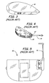
- Figure 1 is a plan view of an implantable cardioverter 10 which includes capacitors 13, a battery 16, and electronics assemblies 19, 20. As shown, for example at arrows 22, a considerable percentage of the volume within the device housing 24 is not used, or is partially used for electrical connection structure 28 protruding from the outer perimeter footprint of components.
- Figure 2 is a plan view of an implantable cardiac defibrillator 30. Again, as shown by protruding electrical connector 33, the result of such protrusions or extensions beyond the perimeter footprint of components creates considerable unusable space shown by arrows 35. This is partly due to the inability of device manufacturers to make components in an integrated manner and with various shapes and sizes of components to accommodate and fit closely around protruding electrical connections.
- Figure 8 shows an external connection for a pulse generator 70, having a headerless design, aligned with the terminal end portion of a stimulating lead 72.
- the lead 72 has a connector 74 attached to the terminal end, wherein the connector 74 is adapted for connection with the feed-through assembly 76 of the pulse generator 70.
- An elastomeric boot 78 is sealingly engaged to the lead 72, whereby the boot may be slid over the lead to the terminal end of the lead, to thereby cover the connector 74.
- the invention of Figure 8 relates to a connection of a stimulating lead for stimulating tissue to the external portion of a stimulation device. The figure not does relate to the connections or packaging between components within an implantable medical device.
- Figures 9- 32 show embodiments of devices, components, assemblies, sub-assemblies and connectors which achieve this goal.
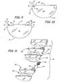
- Figure 9 is a plan view of a cover or housing 85 for a representative component, which in this embodiment is a capacitor.
- the housing has a plurality of outer peripheral surfaces 89, 91, 93, 96, 99, 102 and 105.
- housing 85 has at least one additional surface in plan view.
- the housing shown in Figure 9 discloses a plurality of notched zones 110 formed within an area defined by linear extensions (shown by dashed lines E 1 and E 2 ) of perimeter surfaces of the housing 85 (or energy storage and delivery component). An even smaller zone may be formed using linear extension E 3 , if desired.
- Each notched zone 110 is sized to receive a complex electrical connector (shown and described later herein) which is designed for that zone, and said connector electrically connects at least one energy storage and delivery component to other components or assemblies within an implantable medical device.
- FIG 10 is a plan view of another embodiment of a cover or housing 120 for a capacitor, such as a flat capacitor, which is nominally shaped as a curved semi-circle having surfaces 123, 125. Notched zone 110 is formed by addition of surfaces 127, 129, and, optionally, surface 131.
- the use of a housing is to hold a capacitor assembly as shown in Figure 11 , which is an exploded view of capacitor assembly 144.
- capacitor assembly 144 comprises at least one capacitor 150 (in this embodiment there are two illustrated) and peripheral material including for example positioning or adhesive material 153 and insulation material 155.
- some or all of the peripheral material shown in Figure 11 comprises an outer housing, and therefore the shape of the housing substantially matches that of any underlying capacitor(s) 150.
- a housing may comprise other material surrounding at least part of at least one capacitor having outer surfaces forming at least one notched zone.
- the at least one notched zone is shaped to receive a complex electrical connector external of the housing but within the extended natural footprint (i.e., embedded) of the capacitor (energy storage and delivery device) if the capacitor did not have the peripherally located notched zones formed by additional surfaces.
- Figure 11 also shows an embodiment of a complex electrical connector 180 useful in combination with the formed notched zones described above. It is to be understood that a complex electrical connector means a structure that is more robust than a simple jumper wire or other single wire or single function electrical connection.
- complex connector 180 is configured for attachment in zone 210 with a two sided adhesive material 213, although other attachment structure or method may be useful- provided that the connector is not significantly displaced and protruded out of its zone.
- a goal of the notched zones is to enable placement of a certain inexpensive yet highly reliably manufactured electrical connector 180 in a notched zone so that the connector is not extending above surface 125 or 225.
- the unique placement and configuration of connector 180 optimizes the close engagement, virtually flush mounting, of other components with capacitor 150. In these examples, due to the length of surfaces 125, 225 and the elimination of margin area by such flush mounting, there is considerable savings in volume for a device using this innovation.
- Figure 12 is an elevation view of a single capacitor 300, having a novel notched zone 306 located immediately adjacent to the capacitor electrical leads 309, 311 which extend from epoxy or other structure 315.
- Zone 306 is bounded by the area within linear extensions of two perimeter surfaces 321, 324 of the capacitor and at least one third surface 328 of a perimeter portion 330 of the capacitor.
- Notched zone 306 is designed to receive an embedded complex electrical connector 335, shown in use with a pair of similarly shaped capacitors 300 in Figures 13 and 14 .
- Figure 13 also shows an insulator material 338 placed around the periphery of the combined capacitor hybrid assembly and connector. It is noted that the insulator material includes cutout segments 340 which permit access to conductive pads for either testing or further connection with other components, assemblies, or sub-assemblies within the device.
- Figure 14 is a top view of the hybrid assembly with insulator 338 partially removed to see the wire connections and the relative layout and sizing of the connector 335.
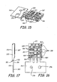
- Figures 15-17 show different views of a connector 335, which in this embodiment has four wire ways 350. It is understood that the invention may include connectors with a variety of wire way configurations.
- Connector 335 is preferably sized for integrated conformal fit within a notched zone of an associated component of an implantable medical device.
- one or more capacitors are selected as representative examples of such a component although other types of components may benefit from use of such a connector and are considered within the scope of this invention.
- electrical connector 335 is made with a stamped metallic portion 363 and an injection molded connector portion 367. It is also possible to use a cast molded resin or epoxy.
- stamped metallic portion 363 provides electrical connection between electrical connectors of the one internal component or assembly and another component or assembly within the implantable medical device.
- the stamped metallic portion is preferably selected from a list of metals including nickel, titanium, copper, aluminum, tantalum, niobium, platinum, platinum family or alloys, stainless steel, palladium, rhodium, or other compatible conductive metals.
- stamped metallic portion 363 comprises a common lead frame 370 and a plurality of conductive stamping legs 374.
- common lead frame 370 has keying structure 376 for positioning the piece during the assembly processes.
- the injection molded connector portion 367 is preferably formed in contact with stamped metallic portion 363 to provide a plurality of wire pathways 350 shaped to receive electrical connectors from at least one internal component or assembly and to guide the internal component or assembly electrical connectors into selective electrical contact with conductive pads 379 on the stamping legs 374.
- Applicants teach a method of assembling an electrical connector to an energy storage and delivery component for use within an implanted medical device. The method comprises the steps of providing an energy storage and delivery component that is shaped to connect with an embedded electrical connector that is sized to fit within a space formed within a notched zone defined by linear extensions of two perimeter surfaces of the energy storage and delivery component. First, a metallic insert is stamped out of raw sheet stock and then metal plated with a conductive plating material.
- the connector portion resin is selected from a list of resins including polyetheramide, polyurethane, nylon and other moldable, high temperature dimensionally stable, high dielectrically constant electrical insulators, having a high flashpoint threshold and a high flow rate.
- the forming step comprises creation of the channel shaped wire-ways (and other functional structure) with each wire way sized to receive an un-insulated electrical wire connector from the energy storage and delivery device component, i.e. capacitor hybrid assembly.
- the electrical connector is positioned in the notched zone on the energy storage and delivery device, and an un-insulated electrical wire is place into one or more of the wire-ways.
- Figures 18-20 show top plan, side elevation and bottom plan views of a connector 335, with the plurality of conductive stamping legs 374 each having at least one conductive pad 382.
- pads 382 are configured as exposed dedicated testing or shorting pads 384, resistance spot weld (RSW) pads 386 for connection of capacitor wires to connector 335, and Lazar Ribbon Bond (LRB) pads 388 for connection points between the associated capacitor hybrid assembly and another portion of the implantable medical device internals.
- RSW resistance spot weld
- LLB Lazar Ribbon Bond
- the connector wire ways 350 are arranged so that two wires 400, 402 connect to a common stamping leg 409 and each of the two additional wires 413, 415 are split among the positive and negative voltage stamping legs 418, 420.
- This facilitates converting four connection points from a two capacitor hybrid assembly 429 into a three connection point arrangement for connection with another portion of the implantable medical device at pads 388.
- Features 449 on the bottom surface of the connector 335 are configured with surfaces to permit improved holding during the molding operation. This facilitates obtaining a flash free surface on the RSW pads 386 as well as providing access to the bottom of pads 386 for opposed electrode resistance spot welding operations. It is understood that although RSW and LRB techniques are currently used to place certain conductive pads, the use of parallel gap welding (PGW), lazar welding, or other techniques may be used for these connections.
- PGW parallel gap welding
- Figures 15, 16 , 18 , and 22 show each wire way 350 separated by a finger element 464 formed by wall portions 466, including tapered or stepped down portions 471. Finger elements 464 of the resinous material extend above the height of the wire when it is placed in each wire way 350 and thereby isolates each wire and prevents wire-to-wire contact within the connector.
- the lengths of wire ways 350 are designed to receive wires which are cut to optimize automatic machine assembly and packaging within the wire ways.
- each wire way wall portion 466 comprises a resilient restriction 485 formed of a pair of opposing wall protrusions 487 shaped to allow a centered press fit of a wire into the wire way and to then resiliently hold the wire in proper place. Again, this facilitates the automatic, efficient, and reliable assembly of the components and the device.
- Figure 17 shows the stamped metallic portion having a breakaway groove 501 in a lower surface 513 between the common lead frame and the stamping legs. That portion of upper surface 515 that is opposite breakaway groove is flat, i.e. without a groove, to assist in the clean break of the material.
- breakaway groove 501 comprises wall portions 518 shaped to allow reliable separation of the common lead frame from the stamping legs to eliminate any post-molding trim of the injection molded connector.
- the wall portions 518 are arranged to direct the separation of the common lead frame from the stamping legs at a location inside an outer periphery of the connector to provide a flash free shutoff at the groove locations.
- Connector 335 is manufactured so that conductive pads 382 are configured at different heights from a lower surface plan of the conductive stamping legs. This is shown in Figures 23-29 , which correspond to the several sectional views of Figure 18 . The different heights are achieved in the stamping process and maintained with tooling in the molding process. The different elevations allow the connecting wires from the capacitor or other components to be routed over electrical pathways that the wires are not to be connected with without concern for shorting to those pathways. Yet another improvement is shown in Figure 30 , in which the conductive pads 382 may have one or more anchor tab structures 592 which extend into the conductive stamping legs and fix the location of the pads to facilitate automated assembly processes. Further reliability and innovation is achieved by use of a directional burr on the upper surface 515 of the metallic portion of the connector to ensure proper shutoffs during the injection molding processes.
- Figures 23-25 and 29 show connector lower surface 513 formed with a curved portion 552 leading up to upper surface 515, and shaped to conform to at least one additional perimeter surface of an associated component, whether it is an energy storage and delivery component, a capacitor, a battery, or another component or assembly.
- This and other features described herein enable advantageous use of an embedded electrical connector that is sized and shaped to fit within a space defined by linear extensions of two perimeter surfaces of a capacitor (or other component/assembly) and by at least one additional perimeter surface of the capacitor (component/assembly) which forms a notched area.
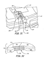
- FIG. 31 illustrates this packaging configuration enabled by use of notched area or zone 610.
- a connector 335 shown electrically connected with component electrical wires 621, 623 and with pads 388 connected to electrical leads of an abutting component 650.
- the packaging innovations of Applicants now permit placement of affected components in an implantable medical device in a relation which virtually eliminates the margin areas (which are common in known devices) around such components.
- At least one capacitor for storing and delivering electrical energy on demand that has at least a 30 Joule capacity, a volume of less than about 36.5 cubic centimeters and a thickness of less than about 14 millimeters.
- the invention includes at least one capacitor for storing and delivering electrical energy on demand which has at least a 30 Joule capacity, a volume of less than about 33 cubic centimeters and a thickness of less than about 13.5 millimeters.
- a further embodiment has at least one flat capacitor for storing and delivering electrical energy on demand, and the capacitor has at least a 30 Joule capacity.
- the device has a volume of less than about 36 cubic centimeters and a thickness of less than about 15 millimeters.
- the capacitor has a related connector for electrically connecting the capacitor with at least one other component within the device.
- the capacitors are shaped to connect with an embedded electrical connector that is sized to fit within a space formed within a zone defined by linear extensions of two perimeter surfaces of the capacitor.
- Another way of expressing this invention is an implantable medical device which has at least one internal component for energy storage and delivery of a defibrillation shock to a user.
- the internal component has a first energy storage and delivery capacity and a first volume, and the internal component is shaped to connect with an embedded electrical connector that is sized to fit within a space formed within a zone defined by linear extensions of two perimeter surfaces of the internal component.
- the first storage and delivery capacity is at least as great as any other known energy storage and delivery internal component less than about 36 Joules, and the first volume is less than the volume of any other identified energy storage and delivery internal component having the identical energy storage and delivery capacity.
- Figure 32 shows a perspective view of another embodiment of an energy storage and delivery component hybrid assembly 703 comprising a plurality of components 706.
- a notched or other shape of a zone 710 is formed so as to permit shared central mounting of a complex electrical connector 735 (shown schematically) within the zone.
- a complex electrical connector 735 shown schematically
- FIG. 32 shows a perspective view of another embodiment of an energy storage and delivery component hybrid assembly 703 comprising a plurality of components 706.
- a notched or other shape of a zone 710 is formed so as to permit shared central mounting of a complex electrical connector 735 (shown schematically) within the zone.
- a complex electrical connector 735 shown schematically
Landscapes
- Engineering & Computer Science (AREA)
- Power Engineering (AREA)
- Health & Medical Sciences (AREA)
- Microelectronics & Electronic Packaging (AREA)
- Public Health (AREA)
- Life Sciences & Earth Sciences (AREA)
- Animal Behavior & Ethology (AREA)
- General Health & Medical Sciences (AREA)
- Radiology & Medical Imaging (AREA)
- Veterinary Medicine (AREA)
- Nuclear Medicine, Radiotherapy & Molecular Imaging (AREA)
- Biomedical Technology (AREA)
- Cardiology (AREA)
- Heart & Thoracic Surgery (AREA)
- Electrotherapy Devices (AREA)
- Prostheses (AREA)
Claims (2)
- Dispositif médical implantable comportant :un ensemble à condensateur (144) comportant au moins un condensateur (150), pour stocker et délivrer de l'énergie électrique à la demande, enfermé à l'intérieur d'un boîtier (85), ledit boîtier ayant des surfaces de périmètre (89, 91, 93, 96, 99, 102, 105) qui établissent une pluralité d'empreintes de composant, dans lequel chacune des empreintes de composant inclut une zone entaillée (210) respective dans une aire définie par des extensions linéaires sécantes de deux surfaces de périmètre du boîtier ; etchaque zone entaillée comporte un bloc de connecteur électrique (180) comportant un ou plusieurs points de connexion pour une connexion à un autre composant à l'intérieur du dispositif médical implantable, chaque bloc de connecteur électrique étant disposé à l'intérieur de sa zone entaillée, chaque bloc de connecteur électrique étant intégré dans son empreinte de composant dans l'aire de celle-ci définie par les extensions linéaires sécantes des deux surfaces de périmètre du boîtier sans faire saillie au-delà d'une frontière établie par les extensions linéaires sécantes des deux surfaces de périmètre.
- Dispositif selon la revendication 1, dans lequel le dispositif est un défibrillateur cardiaque.
Applications Claiming Priority (3)
| Application Number | Priority Date | Filing Date | Title |
|---|---|---|---|
| US10/266,651 US8249710B2 (en) | 2002-10-07 | 2002-10-07 | Complex connector in component footprint of implantable medical device |
| US266651 | 2002-10-07 | ||
| PCT/US2003/031765 WO2004033035A2 (fr) | 2002-10-07 | 2003-10-07 | Connecteur complexe dans l'empreinte d'un element de dispositif medical implantable |
Publications (2)
| Publication Number | Publication Date |
|---|---|
| EP1558337A2 EP1558337A2 (fr) | 2005-08-03 |
| EP1558337B1 true EP1558337B1 (fr) | 2014-09-10 |
Family
ID=32042709
Family Applications (1)
| Application Number | Title | Priority Date | Filing Date |
|---|---|---|---|
| EP03773192.4A Expired - Lifetime EP1558337B1 (fr) | 2002-10-07 | 2003-10-07 | Connecteur complexe dans l'empreinte d'un element de dispositif medical implantable |
Country Status (5)
| Country | Link |
|---|---|
| US (3) | US8249710B2 (fr) |
| EP (1) | EP1558337B1 (fr) |
| JP (1) | JP2006501959A (fr) |
| CA (1) | CA2501654A1 (fr) |
| WO (1) | WO2004033035A2 (fr) |
Families Citing this family (93)
| Publication number | Priority date | Publication date | Assignee | Title |
|---|---|---|---|---|
| US8249710B2 (en) | 2002-10-07 | 2012-08-21 | Medtronic, Inc. | Complex connector in component footprint of implantable medical device |
| US20060271136A1 (en) * | 2005-05-24 | 2006-11-30 | Wojciechowicz Michael T | Electrical connector to terminate, insulate and environmentally isolate multiple temporary cardiac pacing wires |
| DE102006003224A1 (de) * | 2005-12-08 | 2007-06-14 | Biotronik Crm Patent Ag | Gehäuse für ein medizinisches Implantat |
| US8630710B2 (en) * | 2006-03-01 | 2014-01-14 | The Board Of Trustees Of The Leland Stanford Junior University | Implanted cardiac device for defibrillation |
| US8548601B2 (en) * | 2008-09-15 | 2013-10-01 | Boston Scientific Neuromodulation Corporation | Lead connection system for an implantable electrical stimulation system and methods for making and using the systems |
| US8532777B2 (en) | 2008-10-31 | 2013-09-10 | Medtronic, Inc. | Implantable cardioverter defibrillator capacitor assembly with flex circuit |
| US8527054B2 (en) * | 2009-06-30 | 2013-09-03 | Richard B. North | Implantable medical device connector |
| US8521290B2 (en) * | 2009-06-30 | 2013-08-27 | Richard B. North | Implantable medical device connector |
| EP2493564B1 (fr) * | 2009-10-29 | 2016-07-13 | Aortech International plc | Embase en polyuréthane formée directement sur des dispositifs électriques implantables |
| US9724524B2 (en) | 2011-08-02 | 2017-08-08 | Medtronic, Inc. | Interconnection of conductor to feedthrough |
| US8841558B2 (en) | 2011-08-02 | 2014-09-23 | Medtronic Inc. | Hermetic feedthrough |
| US9627833B2 (en) * | 2011-08-02 | 2017-04-18 | Medtronic, Inc. | Electrical leads for a feedthrough |
| US8872035B2 (en) | 2011-08-02 | 2014-10-28 | Medtronic, Inc. | Hermetic feedthrough |
| US8670829B2 (en) | 2011-08-02 | 2014-03-11 | Medtronic, Inc. | Insulator for a feedthrough |
| US8588916B2 (en) | 2011-08-02 | 2013-11-19 | Medtronic, Inc. | Feedthrough configured for interconnect |
| US9008779B2 (en) | 2011-08-02 | 2015-04-14 | Medtronic, Inc. | Insulator for a feedthrough |
| CN107106853B (zh) | 2014-12-01 | 2022-01-07 | 心脏起搏器股份公司 | 具有堆叠的电路组件的植入式医疗设备 |
| ES2713231T3 (es) | 2015-02-06 | 2019-05-20 | Cardiac Pacemakers Inc | Sistemas para el suministro seguro de una terapia de estimulación eléctrica |
| WO2016130477A2 (fr) | 2015-02-09 | 2016-08-18 | Cardiac Pacemakers, Inc. | Dispositif médical implantable comportant une étiquette d'identification radio-opaque |
| EP3265172B1 (fr) | 2015-03-04 | 2018-12-19 | Cardiac Pacemakers, Inc. | Systèmes de traitement d'arythmies cardiaques |
| WO2017031347A1 (fr) | 2015-08-20 | 2017-02-23 | Cardiac Pacemakers, Inc. | Systèmes et procédés de communication entre des dispositifs médicaux |
| US9853743B2 (en) | 2015-08-20 | 2017-12-26 | Cardiac Pacemakers, Inc. | Systems and methods for communication between medical devices |
| US10226631B2 (en) | 2015-08-28 | 2019-03-12 | Cardiac Pacemakers, Inc. | Systems and methods for infarct detection |
| US10137305B2 (en) | 2015-08-28 | 2018-11-27 | Cardiac Pacemakers, Inc. | Systems and methods for behaviorally responsive signal detection and therapy delivery |
| WO2017040115A1 (fr) | 2015-08-28 | 2017-03-09 | Cardiac Pacemakers, Inc. | Système de détection de tamponnade |
| US10065041B2 (en) | 2015-10-08 | 2018-09-04 | Cardiac Pacemakers, Inc. | Devices and methods for adjusting pacing rates in an implantable medical device |
| JP6608063B2 (ja) | 2015-12-17 | 2019-11-20 | カーディアック ペースメイカーズ, インコーポレイテッド | 植込み型医療装置 |
| US10905886B2 (en) | 2015-12-28 | 2021-02-02 | Cardiac Pacemakers, Inc. | Implantable medical device for deployment across the atrioventricular septum |
| WO2017127548A1 (fr) | 2016-01-19 | 2017-07-27 | Cardiac Pacemakers, Inc. | Dispositifs permettant de recharger sans fil une batterie rechargeable d'un dispositif médical implantable |
| WO2017136548A1 (fr) | 2016-02-04 | 2017-08-10 | Cardiac Pacemakers, Inc. | Système de pose avec capteur de force pour dispositif cardiaque sans fil |
| US11116988B2 (en) | 2016-03-31 | 2021-09-14 | Cardiac Pacemakers, Inc. | Implantable medical device with rechargeable battery |
| US10668294B2 (en) | 2016-05-10 | 2020-06-02 | Cardiac Pacemakers, Inc. | Leadless cardiac pacemaker configured for over the wire delivery |
| US10328272B2 (en) | 2016-05-10 | 2019-06-25 | Cardiac Pacemakers, Inc. | Retrievability for implantable medical devices |
| JP6764956B2 (ja) | 2016-06-27 | 2020-10-07 | カーディアック ペースメイカーズ, インコーポレイテッド | 再同期ペーシング管理に皮下で感知されたp波を使用する心臓治療法システム |
| US11207527B2 (en) | 2016-07-06 | 2021-12-28 | Cardiac Pacemakers, Inc. | Method and system for determining an atrial contraction timing fiducial in a leadless cardiac pacemaker system |
| WO2018009392A1 (fr) | 2016-07-07 | 2018-01-11 | Cardiac Pacemakers, Inc. | Stimulateur cardiaque sans fil utilisant des mesures de pression pour la vérification de la capture de stimulation |
| CN109475743B (zh) | 2016-07-20 | 2022-09-02 | 心脏起搏器股份公司 | 在无引线心脏起搏器系统中利用心房收缩定时基准的系统 |
| WO2018035343A1 (fr) | 2016-08-19 | 2018-02-22 | Cardiac Pacemakers, Inc. | Dispositif médical implantable trans-septal |
| EP3503970B1 (fr) | 2016-08-24 | 2023-01-04 | Cardiac Pacemakers, Inc. | Resynchronisation cardiaque utilisant l'encouragement de la fusion pour la gestion de la synchronisation |
| CN109640809B (zh) | 2016-08-24 | 2021-08-17 | 心脏起搏器股份公司 | 使用p波到起搏定时的集成式多装置心脏再同步治疗 |
| WO2018057626A1 (fr) | 2016-09-21 | 2018-03-29 | Cardiac Pacemakers, Inc. | Moniteur cardiaque implantable |
| WO2018057318A1 (fr) | 2016-09-21 | 2018-03-29 | Cardiac Pacemakers, Inc. | Dispositif de stimulation sans fil muni d'un boîtier qui abrite des composants interne du dispositif de stimulation sans fil et fonctionne comme boîtier de batterie et borne d'une batterie interne |
| US10758737B2 (en) | 2016-09-21 | 2020-09-01 | Cardiac Pacemakers, Inc. | Using sensor data from an intracardially implanted medical device to influence operation of an extracardially implantable cardioverter |
| WO2018081237A1 (fr) | 2016-10-27 | 2018-05-03 | Cardiac Pacemakers, Inc. | Utilisation d'un dispositif séparé pour gérer l'énergie d'impulsion de stimulation d'un stimulateur cardiaque |
| US10413733B2 (en) | 2016-10-27 | 2019-09-17 | Cardiac Pacemakers, Inc. | Implantable medical device with gyroscope |
| WO2018081275A1 (fr) | 2016-10-27 | 2018-05-03 | Cardiac Pacemakers, Inc. | Thérapie de resynchronisation cardiaque à dispositifs multiples avec des améliorations de synchronisation |
| WO2018081133A1 (fr) | 2016-10-27 | 2018-05-03 | Cardiac Pacemakers, Inc. | Dispositif médical implantable présentant un canal d'écoute à réglage de rendement |
| US10758724B2 (en) | 2016-10-27 | 2020-09-01 | Cardiac Pacemakers, Inc. | Implantable medical device delivery system with integrated sensor |
| AU2017350759B2 (en) | 2016-10-27 | 2019-10-17 | Cardiac Pacemakers, Inc. | Implantable medical device with pressure sensor |
| US10434317B2 (en) | 2016-10-31 | 2019-10-08 | Cardiac Pacemakers, Inc. | Systems and methods for activity level pacing |
| EP3532157B1 (fr) | 2016-10-31 | 2020-08-26 | Cardiac Pacemakers, Inc. | Systèmes de stimulation de niveau d'activité |
| WO2018089311A1 (fr) | 2016-11-08 | 2018-05-17 | Cardiac Pacemakers, Inc | Dispositif médical implantable pour déploiement auriculaire |
| WO2018089308A1 (fr) | 2016-11-09 | 2018-05-17 | Cardiac Pacemakers, Inc. | Systèmes, dispositifs et procédés pour régler des paramètres d'impulsion de stimulation cardiaque pour un dispositif de stimulation cardiaque |
| EP3541473B1 (fr) | 2016-11-21 | 2020-11-11 | Cardiac Pacemakers, Inc. | Stimulateur cardiaque sans sonde à communication multimodale |
| CN109982746B (zh) | 2016-11-21 | 2023-04-04 | 心脏起搏器股份公司 | 提供心脏再同步治疗的无引线心脏起搏器 |
| US10881869B2 (en) | 2016-11-21 | 2021-01-05 | Cardiac Pacemakers, Inc. | Wireless re-charge of an implantable medical device |
| EP3541472B1 (fr) | 2016-11-21 | 2023-06-07 | Cardiac Pacemakers, Inc. | Dispositif médical implantable comportant un boîtier magnétiquement perméable et une bobine inductive placée autour du boîtier |
| US10639486B2 (en) | 2016-11-21 | 2020-05-05 | Cardiac Pacemakers, Inc. | Implantable medical device with recharge coil |
| US11207532B2 (en) | 2017-01-04 | 2021-12-28 | Cardiac Pacemakers, Inc. | Dynamic sensing updates using postural input in a multiple device cardiac rhythm management system |
| CN110198759B (zh) | 2017-01-26 | 2023-08-11 | 心脏起搏器股份公司 | 具有可拆卸固定件的无引线可植入装置 |
| JP7000438B2 (ja) | 2017-01-26 | 2022-01-19 | カーディアック ペースメイカーズ, インコーポレイテッド | 冗長メッセージ送信を伴う人体デバイス通信 |
| CN110234392B (zh) | 2017-01-26 | 2023-08-11 | 心脏起搏器股份公司 | 具有被包覆模制的组件的无引线装置 |
| US10821288B2 (en) | 2017-04-03 | 2020-11-03 | Cardiac Pacemakers, Inc. | Cardiac pacemaker with pacing pulse energy adjustment based on sensed heart rate |
| US10905872B2 (en) | 2017-04-03 | 2021-02-02 | Cardiac Pacemakers, Inc. | Implantable medical device with a movable electrode biased toward an extended position |
| EP3668592B1 (fr) | 2017-08-18 | 2021-11-17 | Cardiac Pacemakers, Inc. | Dispositif médical implantable avec capteur de pression |
| WO2019036568A1 (fr) | 2017-08-18 | 2019-02-21 | Cardiac Pacemakers, Inc. | Dispositif médical implantable comprenant un concentrateur de flux et une bobine de réception disposée autour du concentrateur de flux |
| JP6938778B2 (ja) | 2017-09-20 | 2021-09-22 | カーディアック ペースメイカーズ, インコーポレイテッド | 複数の作動モードを備えた移植式医療用装置 |
| US11185703B2 (en) | 2017-11-07 | 2021-11-30 | Cardiac Pacemakers, Inc. | Leadless cardiac pacemaker for bundle of his pacing |
| EP3717060B1 (fr) | 2017-12-01 | 2022-10-05 | Cardiac Pacemakers, Inc. | Stimulateur cardiaque sans fil à comportement réversible |
| EP3717063B1 (fr) | 2017-12-01 | 2023-12-27 | Cardiac Pacemakers, Inc. | Systèmes pour détecter des repères de synchronisation de contraction auriculaire et pour déterminer un intervalle cardiaque à partir d'un stimulateur cardiaque sans fil implanté de manière ventriculaire |
| EP3717059B1 (fr) | 2017-12-01 | 2024-11-20 | Cardiac Pacemakers, Inc. | Systèmes pour détecter des repères de synchronisation de contraction auriculaire dans une fenêtre de recherche à partir d'un stimulateur cardiaque sans fil implanté de manière ventriculaire |
| WO2019108545A1 (fr) | 2017-12-01 | 2019-06-06 | Cardiac Pacemakers, Inc. | Procédés et systèmes pour détecter des repères de synchronisation de contraction auriculaire pendant un remplissage ventriculaire à partir d'un stimulateur cardiaque sans fil implanté de manière ventriculaire |
| US11529523B2 (en) | 2018-01-04 | 2022-12-20 | Cardiac Pacemakers, Inc. | Handheld bridge device for providing a communication bridge between an implanted medical device and a smartphone |
| EP3735293B1 (fr) | 2018-01-04 | 2022-03-09 | Cardiac Pacemakers, Inc. | Stimulation double chambre sans communication battement à battement |
| EP3768369A1 (fr) | 2018-03-23 | 2021-01-27 | Medtronic, Inc. | Thérapie cardiaque du ventricule vers l'atrium (vfa) synchrone atrioventriculaire (av) |
| JP2021518192A (ja) | 2018-03-23 | 2021-08-02 | メドトロニック,インコーポレイテッド | VfA心臓再同期治療 |
| US11058880B2 (en) | 2018-03-23 | 2021-07-13 | Medtronic, Inc. | VFA cardiac therapy for tachycardia |
| EP3856331A1 (fr) | 2018-09-26 | 2021-08-04 | Medtronic, Inc. | Capture dans une thérapie cardiaque du ventricule à partir de l'oreillette |
| US11951313B2 (en) | 2018-11-17 | 2024-04-09 | Medtronic, Inc. | VFA delivery systems and methods |
| EP3897816B1 (fr) | 2018-12-21 | 2024-03-27 | Medtronic, Inc. | Systèmes de pose pour stimulation ventriculaire gauche |
| US11679265B2 (en) | 2019-02-14 | 2023-06-20 | Medtronic, Inc. | Lead-in-lead systems and methods for cardiac therapy |
| US11697025B2 (en) | 2019-03-29 | 2023-07-11 | Medtronic, Inc. | Cardiac conduction system capture |
| US11213676B2 (en) | 2019-04-01 | 2022-01-04 | Medtronic, Inc. | Delivery systems for VfA cardiac therapy |
| US11712188B2 (en) | 2019-05-07 | 2023-08-01 | Medtronic, Inc. | Posterior left bundle branch engagement |
| US11305127B2 (en) | 2019-08-26 | 2022-04-19 | Medtronic Inc. | VfA delivery and implant region detection |
| US11813466B2 (en) | 2020-01-27 | 2023-11-14 | Medtronic, Inc. | Atrioventricular nodal stimulation |
| US12543992B2 (en) | 2020-03-30 | 2026-02-10 | Medtronic, Inc. | Pacing efficacy determination using a representative morphology of external cardiac signals |
| US11911168B2 (en) | 2020-04-03 | 2024-02-27 | Medtronic, Inc. | Cardiac conduction system therapy benefit determination |
| US12605103B2 (en) | 2020-05-21 | 2026-04-21 | Medtronic, Inc. | QRS detection and bracketing |
| US12465770B2 (en) | 2020-07-31 | 2025-11-11 | Medtronic, Inc. | Coronary sinus conduction system pacing and delivery |
| US11813464B2 (en) | 2020-07-31 | 2023-11-14 | Medtronic, Inc. | Cardiac conduction system evaluation |
| EP4259271B1 (fr) * | 2020-12-11 | 2025-03-19 | BIOTRONIK SE & Co. KG | Composant électrique pour un dispositif médical implantable |
| CN117597657A (zh) * | 2021-06-08 | 2024-02-23 | 安裕创新有限公司 | 可重新配置的键盘 |
Family Cites Families (33)
| Publication number | Priority date | Publication date | Assignee | Title |
|---|---|---|---|---|
| US669265A (en) * | 1900-10-22 | 1901-03-05 | Norton Brothers | Furnace for heating metal bars or sheets. |
| GB2141583A (en) * | 1983-06-17 | 1984-12-19 | Standard Telephones Cables Ltd | Leadless capacitors |
| US5522851A (en) * | 1994-12-06 | 1996-06-04 | Ventritex, Inc. | Capacitor for an implantable cardiac defibrillator |
| US6014586A (en) * | 1995-11-20 | 2000-01-11 | Pacesetter, Inc. | Vertically integrated semiconductor package for an implantable medical device |
| US5926357A (en) * | 1995-12-05 | 1999-07-20 | Pacesetter, Inc. | Aluminum electrolytic capacitor for implantable medical device |
| US5801917A (en) * | 1996-06-03 | 1998-09-01 | Pacesetter, Inc. | Capacitor for an implantable cardiac defibrillator |
| US5814082A (en) * | 1997-04-23 | 1998-09-29 | Pacesetter, Inc. | Layered capacitor with alignment elements for an implantable cardiac defibrillator |
| US6040082A (en) * | 1997-07-30 | 2000-03-21 | Medtronic, Inc. | Volumetrically efficient battery for implantable medical devices |
| US5954751A (en) * | 1998-01-15 | 1999-09-21 | Intermedics Inc. | Implantable defibrillator with stacked transistor subassemblies |
| US6099600A (en) * | 1998-04-03 | 2000-08-08 | Medtronic, Inc. | Method of making a vacuum-treated liquid electrolyte-filled flat electrolytic capacitor |
| US6118652A (en) * | 1998-04-03 | 2000-09-12 | Medtronic, Inc. | Implantable medical device having flat electrolytic capacitor with laser welded cover |
| US6402793B1 (en) | 1998-04-03 | 2002-06-11 | Medtronic, Inc. | Implantable medical device having flat electrolytic capacitor with cathode/case electrical connections |
| US6032075A (en) * | 1998-04-03 | 2000-02-29 | Medtronic, Inc. | Implantable medical device with flat aluminum electolytic capacitor |
| US6212063B1 (en) * | 1998-04-03 | 2001-04-03 | Medtronic, Inc. | Implantable medical device having flat electrolytic capacitor with connector block and sealed feedthroughs |
| US6388866B1 (en) * | 1998-04-03 | 2002-05-14 | Medtronic, Inc. | Implantable medical device having flat electrolytic capacitor with tailored anode layers |
| US6445948B1 (en) * | 1998-04-03 | 2002-09-03 | Medtronic, Inc. | Implantable medical device having a substantially flat battery |
| US6009348A (en) * | 1998-04-03 | 1999-12-28 | Medtronic, Inc. | Implantable medical device having flat electrolytic capacitor with registered electrode layers |
| US6141205A (en) * | 1998-04-03 | 2000-10-31 | Medtronic, Inc. | Implantable medical device having flat electrolytic capacitor with consolidated electrode tabs and corresponding feedthroughs |
| US6187028B1 (en) * | 1998-04-23 | 2001-02-13 | Intermedics Inc. | Capacitors having metallized film with tapered thickness |
| US6243605B1 (en) * | 1998-05-06 | 2001-06-05 | Cardiac Pacemakers, Inc. | Cardiac rhythm management system having multi-capacitor module |
| US6110233A (en) * | 1998-05-11 | 2000-08-29 | Cardiac Pacemakers, Inc. | Wound multi-anode electrolytic capacitor with offset anodes |
| US6026325A (en) * | 1998-06-18 | 2000-02-15 | Pacesetter, Inc. | Implantable medical device having an improved packaging system and method for making electrical connections |
| US6459566B1 (en) * | 1998-06-24 | 2002-10-01 | Medtronic, Inc. | Implantable medical device having flat electrolytic capacitor with laser welded cover |
| US6191931B1 (en) * | 1998-08-28 | 2001-02-20 | Pacesetter, Inc. | Aluminum electrolytic capacitor with conductive feed-through for implantable medical device |
| TW398681U (en) | 1998-12-24 | 2000-07-11 | Hon Hai Prec Ind Co Ltd | Electrical connector |
| US6678559B1 (en) | 1999-03-23 | 2004-01-13 | Medtronic, Inc. | Implantable medical device having a capacitor assembly with liner |
| US6385490B1 (en) * | 1999-12-16 | 2002-05-07 | Cardiac Pacemakers, Inc. | Capacitors with recessed rivets allow smaller implantable defibrillators |
| US6426864B1 (en) | 2000-06-29 | 2002-07-30 | Cardiac Pacemakers, Inc. | High energy capacitors for implantable defibrillators |
| US6571126B1 (en) * | 2000-11-03 | 2003-05-27 | Cardiac Pacemakers, Inc. | Method of constructing a capacitor stack for a flat capacitor |
| US6699265B1 (en) * | 2000-11-03 | 2004-03-02 | Cardiac Pacemakers, Inc. | Flat capacitor for an implantable medical device |
| US6731512B2 (en) * | 2002-03-20 | 2004-05-04 | The Procter & Gamble Company | Active package for integrated circuit |
| US6799072B2 (en) * | 2002-04-25 | 2004-09-28 | Medtronic, Inc. | Electrically insulated component sub-assemblies of implantable medical devices |
| US8249710B2 (en) | 2002-10-07 | 2012-08-21 | Medtronic, Inc. | Complex connector in component footprint of implantable medical device |
-
2002
- 2002-10-07 US US10/266,651 patent/US8249710B2/en not_active Expired - Fee Related
-
2003
- 2003-10-07 CA CA002501654A patent/CA2501654A1/fr not_active Abandoned
- 2003-10-07 JP JP2004543473A patent/JP2006501959A/ja active Pending
- 2003-10-07 EP EP03773192.4A patent/EP1558337B1/fr not_active Expired - Lifetime
- 2003-10-07 WO PCT/US2003/031765 patent/WO2004033035A2/fr not_active Ceased
-
2005
- 2005-11-30 US US11/290,282 patent/US8386044B2/en not_active Expired - Fee Related
-
2013
- 2013-02-26 US US13/777,625 patent/US8825160B2/en not_active Expired - Fee Related
Also Published As
| Publication number | Publication date |
|---|---|
| EP1558337A2 (fr) | 2005-08-03 |
| US8386044B2 (en) | 2013-02-26 |
| JP2006501959A (ja) | 2006-01-19 |
| WO2004033035A3 (fr) | 2004-09-16 |
| CA2501654A1 (fr) | 2004-04-22 |
| US20130238071A1 (en) | 2013-09-12 |
| US8249710B2 (en) | 2012-08-21 |
| US20060172611A1 (en) | 2006-08-03 |
| WO2004033035A2 (fr) | 2004-04-22 |
| US20040068302A1 (en) | 2004-04-08 |
| US8825160B2 (en) | 2014-09-02 |
Similar Documents
| Publication | Publication Date | Title |
|---|---|---|
| EP1558337B1 (fr) | Connecteur complexe dans l'empreinte d'un element de dispositif medical implantable | |
| EP2370174B1 (fr) | Ensemble de condensateur pour defibrillateur cardioverteur implantable avec un circuit souple | |
| US7647110B2 (en) | Modular implantable medical device and manufacturing method therefor | |
| EP1418983B1 (fr) | Assemblage de dispositif medical implantable et procede de fabrication | |
| US6191931B1 (en) | Aluminum electrolytic capacitor with conductive feed-through for implantable medical device | |
| EP1998851B1 (fr) | Connecteur d'interface pour dispositif implantable | |
| US7794256B1 (en) | Implantable connector with contact-containing feedthrough pins | |
| US7467013B2 (en) | Ring connector for implantable medical devices | |
| US8095217B2 (en) | Terminal housing for an electromedical implant | |
| US20170157405A1 (en) | Implantable medical devices and related connector enclosure assemblies utilizing conductors electrically coupled to feedthrough pins | |
| EP0715867A2 (fr) | Condensateur amélioré pour un défibrillateur cardiaque implantable | |
| US20070150020A1 (en) | Externally oriented battery feedthrough with integral connector | |
| US20070247786A1 (en) | Torroidal battery for use in implantable medical device | |
| US7515964B1 (en) | Multi-directional bore configuration header | |
| US10965082B2 (en) | Plug with an over-molded, non-rotatable plug connector and four connectors, in particular an IS4/DF4 plug | |
| US20140277216A1 (en) | Implantable device with opposing lead connectors | |
| US9379507B2 (en) | Feedthrough system for implantable device components | |
| US10071253B2 (en) | Implantable device with internal lead connector | |
| CN116747435A (zh) | 神经刺激器及神经刺激器制造方法 |
Legal Events
| Date | Code | Title | Description |
|---|---|---|---|
| PUAI | Public reference made under article 153(3) epc to a published international application that has entered the european phase |
Free format text: ORIGINAL CODE: 0009012 |
|
| 17P | Request for examination filed |
Effective date: 20050503 |
|
| AK | Designated contracting states |
Kind code of ref document: A2 Designated state(s): AT BE BG CH CY CZ DE DK EE ES FI FR GB GR HU IE IT LI LU MC NL PT RO SE SI SK TR |
|
| RBV | Designated contracting states (corrected) |
Designated state(s): CH DE FR LI NL SE |
|
| 17Q | First examination report despatched |
Effective date: 20111017 |
|
| GRAP | Despatch of communication of intention to grant a patent |
Free format text: ORIGINAL CODE: EPIDOSNIGR1 |
|
| INTG | Intention to grant announced |
Effective date: 20140321 |
|
| GRAS | Grant fee paid |
Free format text: ORIGINAL CODE: EPIDOSNIGR3 |
|
| GRAA | (expected) grant |
Free format text: ORIGINAL CODE: 0009210 |
|
| AK | Designated contracting states |
Kind code of ref document: B1 Designated state(s): CH DE FR LI NL SE |
|
| REG | Reference to a national code |
Ref country code: CH Ref legal event code: EP |
|
| REG | Reference to a national code |
Ref country code: DE Ref legal event code: R096 Ref document number: 60346739 Country of ref document: DE Effective date: 20141016 |
|
| PG25 | Lapsed in a contracting state [announced via postgrant information from national office to epo] |
Ref country code: SE Free format text: LAPSE BECAUSE OF FAILURE TO SUBMIT A TRANSLATION OF THE DESCRIPTION OR TO PAY THE FEE WITHIN THE PRESCRIBED TIME-LIMIT Effective date: 20140910 |
|
| REG | Reference to a national code |
Ref country code: NL Ref legal event code: VDEP Effective date: 20140910 |
|
| PG25 | Lapsed in a contracting state [announced via postgrant information from national office to epo] |
Ref country code: NL Free format text: LAPSE BECAUSE OF FAILURE TO SUBMIT A TRANSLATION OF THE DESCRIPTION OR TO PAY THE FEE WITHIN THE PRESCRIBED TIME-LIMIT Effective date: 20140910 |
|
| REG | Reference to a national code |
Ref country code: CH Ref legal event code: PL |
|
| REG | Reference to a national code |
Ref country code: DE Ref legal event code: R097 Ref document number: 60346739 Country of ref document: DE |
|
| PLBE | No opposition filed within time limit |
Free format text: ORIGINAL CODE: 0009261 |
|
| STAA | Information on the status of an ep patent application or granted ep patent |
Free format text: STATUS: NO OPPOSITION FILED WITHIN TIME LIMIT |
|
| PG25 | Lapsed in a contracting state [announced via postgrant information from national office to epo] |
Ref country code: CH Free format text: LAPSE BECAUSE OF NON-PAYMENT OF DUE FEES Effective date: 20141031 Ref country code: LI Free format text: LAPSE BECAUSE OF NON-PAYMENT OF DUE FEES Effective date: 20141031 |
|
| 26N | No opposition filed |
Effective date: 20150611 |
|
| REG | Reference to a national code |
Ref country code: FR Ref legal event code: PLFP Year of fee payment: 13 |
|
| REG | Reference to a national code |
Ref country code: FR Ref legal event code: PLFP Year of fee payment: 14 |
|
| PGFP | Annual fee paid to national office [announced via postgrant information from national office to epo] |
Ref country code: FR Payment date: 20161025 Year of fee payment: 14 Ref country code: DE Payment date: 20161027 Year of fee payment: 14 |
|
| REG | Reference to a national code |
Ref country code: DE Ref legal event code: R119 Ref document number: 60346739 Country of ref document: DE |
|
| REG | Reference to a national code |
Ref country code: FR Ref legal event code: ST Effective date: 20180629 |
|
| PG25 | Lapsed in a contracting state [announced via postgrant information from national office to epo] |
Ref country code: DE Free format text: LAPSE BECAUSE OF NON-PAYMENT OF DUE FEES Effective date: 20180501 |
|
| PG25 | Lapsed in a contracting state [announced via postgrant information from national office to epo] |
Ref country code: FR Free format text: LAPSE BECAUSE OF NON-PAYMENT OF DUE FEES Effective date: 20171031 |