EP1558118B1 - Für getränkemaschine geeignetes system - Google Patents
Für getränkemaschine geeignetes system Download PDFInfo
- Publication number
- EP1558118B1 EP1558118B1 EP03773393A EP03773393A EP1558118B1 EP 1558118 B1 EP1558118 B1 EP 1558118B1 EP 03773393 A EP03773393 A EP 03773393A EP 03773393 A EP03773393 A EP 03773393A EP 1558118 B1 EP1558118 B1 EP 1558118B1
- Authority
- EP
- European Patent Office
- Prior art keywords
- particulate
- component
- plug
- beverage
- beverage machine
- Prior art date
- Legal status (The legal status is an assumption and is not a legal conclusion. Google has not performed a legal analysis and makes no representation as to the accuracy of the status listed.)
- Expired - Lifetime
Links
- 235000013361 beverage Nutrition 0.000 title claims abstract description 112
- 239000000126 substance Substances 0.000 claims description 67
- 235000013336 milk Nutrition 0.000 claims description 33
- 239000008267 milk Substances 0.000 claims description 33
- 210000004080 milk Anatomy 0.000 claims description 33
- 235000013353 coffee beverage Nutrition 0.000 claims description 22
- 230000003993 interaction Effects 0.000 claims description 19
- 235000016213 coffee Nutrition 0.000 claims description 15
- 230000005484 gravity Effects 0.000 claims description 10
- 239000012736 aqueous medium Substances 0.000 claims description 6
- 238000000605 extraction Methods 0.000 claims description 6
- 239000002245 particle Substances 0.000 claims description 2
- XLYOFNOQVPJJNP-UHFFFAOYSA-N water Substances O XLYOFNOQVPJJNP-UHFFFAOYSA-N 0.000 abstract description 125
- 239000012530 fluid Substances 0.000 abstract description 28
- 239000011236 particulate material Substances 0.000 abstract description 19
- 238000002360 preparation method Methods 0.000 description 37
- 238000001514 detection method Methods 0.000 description 25
- 239000000463 material Substances 0.000 description 15
- 230000007246 mechanism Effects 0.000 description 15
- 240000007154 Coffea arabica Species 0.000 description 14
- 238000004891 communication Methods 0.000 description 13
- 239000000843 powder Substances 0.000 description 12
- 230000002093 peripheral effect Effects 0.000 description 11
- 230000004044 response Effects 0.000 description 11
- 238000006073 displacement reaction Methods 0.000 description 8
- 235000008476 powdered milk Nutrition 0.000 description 8
- 230000007257 malfunction Effects 0.000 description 7
- 238000000034 method Methods 0.000 description 5
- 230000008569 process Effects 0.000 description 5
- 244000269722 Thea sinensis Species 0.000 description 4
- 230000004913 activation Effects 0.000 description 4
- 235000015114 espresso Nutrition 0.000 description 4
- 235000013616 tea Nutrition 0.000 description 4
- 244000299461 Theobroma cacao Species 0.000 description 3
- 235000009470 Theobroma cacao Nutrition 0.000 description 3
- 235000015116 cappuccino Nutrition 0.000 description 3
- 230000005611 electricity Effects 0.000 description 3
- 235000020278 hot chocolate Nutrition 0.000 description 3
- 239000000654 additive Substances 0.000 description 2
- 230000000996 additive effect Effects 0.000 description 2
- XAGFODPZIPBFFR-UHFFFAOYSA-N aluminium Chemical compound [Al] XAGFODPZIPBFFR-UHFFFAOYSA-N 0.000 description 2
- 229910052782 aluminium Inorganic materials 0.000 description 2
- 239000004020 conductor Substances 0.000 description 2
- 238000010586 diagram Methods 0.000 description 2
- 235000015092 herbal tea Nutrition 0.000 description 2
- 239000000615 nonconductor Substances 0.000 description 2
- 230000005855 radiation Effects 0.000 description 2
- 235000000346 sugar Nutrition 0.000 description 2
- 238000011144 upstream manufacturing Methods 0.000 description 2
- 240000004178 Anthoxanthum odoratum Species 0.000 description 1
- CDBYLPFSWZWCQE-UHFFFAOYSA-L Sodium Carbonate Chemical compound [Na+].[Na+].[O-]C([O-])=O CDBYLPFSWZWCQE-UHFFFAOYSA-L 0.000 description 1
- 230000009471 action Effects 0.000 description 1
- 239000000853 adhesive Substances 0.000 description 1
- 230000001070 adhesive effect Effects 0.000 description 1
- 230000000712 assembly Effects 0.000 description 1
- 238000000429 assembly Methods 0.000 description 1
- 230000000903 blocking effect Effects 0.000 description 1
- 235000015109 caffè americano Nutrition 0.000 description 1
- 235000015115 caffè latte Nutrition 0.000 description 1
- 238000006243 chemical reaction Methods 0.000 description 1
- 235000020140 chocolate milk drink Nutrition 0.000 description 1
- 230000006835 compression Effects 0.000 description 1
- 238000007906 compression Methods 0.000 description 1
- 230000001419 dependent effect Effects 0.000 description 1
- 238000007599 discharging Methods 0.000 description 1
- 230000000694 effects Effects 0.000 description 1
- 239000000796 flavoring agent Substances 0.000 description 1
- 235000019634 flavors Nutrition 0.000 description 1
- 238000005187 foaming Methods 0.000 description 1
- 235000013355 food flavoring agent Nutrition 0.000 description 1
- 230000007274 generation of a signal involved in cell-cell signaling Effects 0.000 description 1
- 239000003292 glue Substances 0.000 description 1
- 238000010438 heat treatment Methods 0.000 description 1
- 239000008236 heating water Substances 0.000 description 1
- 238000007373 indentation Methods 0.000 description 1
- 235000021539 instant coffee Nutrition 0.000 description 1
- 230000013011 mating Effects 0.000 description 1
- 238000013021 overheating Methods 0.000 description 1
- 238000004806 packaging method and process Methods 0.000 description 1
- 230000037361 pathway Effects 0.000 description 1
- 238000005086 pumping Methods 0.000 description 1
- 235000014214 soft drink Nutrition 0.000 description 1
Images


Classifications
-
- A—HUMAN NECESSITIES
- A47—FURNITURE; DOMESTIC ARTICLES OR APPLIANCES; COFFEE MILLS; SPICE MILLS; SUCTION CLEANERS IN GENERAL
- A47J—KITCHEN EQUIPMENT; COFFEE MILLS; SPICE MILLS; APPARATUS FOR MAKING BEVERAGES
- A47J31/00—Apparatus for making beverages
- A47J31/40—Beverage-making apparatus with dispensing means for adding a measured quantity of ingredients, e.g. coffee, water, sugar, cocoa, milk, tea
- A47J31/404—Powder dosing devices
-
- A—HUMAN NECESSITIES
- A47—FURNITURE; DOMESTIC ARTICLES OR APPLIANCES; COFFEE MILLS; SPICE MILLS; SUCTION CLEANERS IN GENERAL
- A47J—KITCHEN EQUIPMENT; COFFEE MILLS; SPICE MILLS; APPARATUS FOR MAKING BEVERAGES
- A47J31/00—Apparatus for making beverages
- A47J31/40—Beverage-making apparatus with dispensing means for adding a measured quantity of ingredients, e.g. coffee, water, sugar, cocoa, milk, tea
- A47J31/401—Beverage-making apparatus with dispensing means for adding a measured quantity of ingredients, e.g. coffee, water, sugar, cocoa, milk, tea whereby the powder ingredients and the water are delivered to a mixing bowl
Definitions
- the present invention relates to systems, assemblies, combinations, etc. which may be incorporated into beverage making machines, for example (automatic) beverage making machines and in particular beverage making machine able to provide a selection of two or more beverage types.
- the present invention will be discussed in relation to coffee beverages but is applicable generally to any beverage making machine which is able to provide any type of beverage in addition to or in the alternative to coffee beverages, e.g. tea, herbal tea, milk, chocolate milk hot chocolate drink, soft drinks, etc..
- coffee beverages e.g. tea, herbal tea, milk, chocolate milk hot chocolate drink, soft drinks, etc.
- the present invention will be discussed in particular with respect to a machine which may provide a choice between a number of beverages various aspect such as the storage aspect and water heater may be used in a machine offering a single choice of beverage.
- Beverage machines which exploit particulate substances for the preparation of a beverage; such particulate substances may be used for the preparation of the base beverage itself, e.g. coffee, tea, milk, etc.. ; such particulate substances may also used be for the exploitation of a (soluble) flavor additive substance such powdered milk, sugar, cocoa, etc..
- a (soluble) flavor additive substance such powdered milk, sugar, cocoa, etc.
- Beverage machines e.g. automatic beverage machine
- beverage machines which are able to provide individual servings of a beverage which is selectable from among a plurality of beverage types various beverages including hot or cold coffee, tea, hot chocolate, and cold soda; known machines also permit the consumer to choose from a variety of items to add to the beverage to alter the flavor of the drink (e.g. milk).
- U.S.patent publication no. US 2002/00960054 ( U.S. appln. no. 10/046,662 ), for example describes, in relation to a coffee beverage machine, the replacement of a plurality of push button (i.e. contact) type selection mechanisms, by a rotary contact selection mechanism.
- the rotary switch contact selection mechanism is configured such that it may be rotated between a plurality of releasably lockable positions, each position being associated with a switch contact group which in turn is associated with the preparation of a particular beverage type.
- Hot water dispensing systems are also known for use with machines for the preparation of beverages.
- Such a system may include among other things a hot water heater, a pump for displacing water to and from the water heater, fluid conduits, valves etc.
- Such a system may break down and leak water to the point where the heater and pump may inadvertently be called upon to function in the absence of water which could lead to significant damage to parts of the system e.g. due to overheating.
- a device for packaging, transportation and despensing of a ground or pulverized matter is known.
- a metering conveyor screw is used for dispensing the matter into a catching cup.
- a container for storing the matter has a aluminum seal over an opening and the aluminum seal is removed for attachment of a portioning facility to the unsealed opening.
- a container for ground matter comprises rotatable blades for blocking or unblocking an outlet opening for the matter. Transferring a measure of the matter takes place on rotation of the blades. The container is opened or closed according to an operation state of the motor rotating the blades.
- the present invention relates to a lid, namely to a (removable or) detachable valved lid element for covering an opening of a case element said lid element being configured to co-operate with said case element such that said lid element is removably attachable to said case element so as to cover said opening and form an enclosed space (e.g. chamber) for containing a particulate substance (e.g.
- said lid element comprising a valve member having an outflow aperture and defining a flow path for the flow of particulate material out of said enclosed space, said valve member further comprising a plug element and a bias component, said plug element and said bias component being configured such that said plug element is displacable between a closed position and an open position whereby when said plug element is in said closed position said plug closes off said outflow aperture whereby particulate material (e.g. powder) is unable to flow out of said enclosed space (e.g. chamber) through said outflow aperture and when said plug element is in said open position particulate material (e.g. powder) is able to flow out of said enclosed space (e.g. chamber) through said outflow aperture, said bias element biasing said plug element in said closed position.
- particulate material e.g. powder
- a valved lid element may (itself) comprise a valve plug interaction element for releasably maintaining (i.e. for urging) said plug in said open position (i.e. against said bias element).
- the lid and case elements may be of any material keeping in mind the purpose thereof, i.e. to provide a free gravity induced flow of particles out of the case element.
- the case element may have wall(s) at least in the area adjacent to the opening which are rigid in the sense of being self-supporting (can stand up alone under the influence of gravity) as against a wall structure(s) which is not self-supporting, i.e. collapsible under the influence of gravity.
- the case element may have a cylindrical or tubular aspect, i.e. form.
- the lid element may have any suitable attachment structures for removably attaching the lid element to the case element, screw threads, friction fit members, L-shaped slot for engaging a pin, a pin for engaging an L-shaped slot, etc..
- the present invention relates to a particulate storage [assembly or] combination (i.e. cartridge) comprising a case element having an opening and a (removable or) detachable valved lid element said case element and said lid element being configured such that said lid element is removably attached(able) to said case element so as to cover said opening and form an enclosed space (e.g. chamber) for containing a particulate substance (e.g.
- said lid element comprising a valve member having an outflow aperture and defining a flow path for the flow of particulate material out of said enclosed space, said valve member further comprising a plug element and a bias component, said plug element and said bias component being configured such that said plug element is displacable between a closed position and an open position whereby when said plug element is in said closed position said plug closes off said outflow aperture whereby particulate material (e.g. powder) is unable to flow out of said enclosed space (e.g. chamber) through said outflow aperture and when said plug element is in said open position particulate material (e.g. powder) is able to flow out of said enclosed space (e.g. chamber) through said outflow aperture, said bias element biasing said plug element in said closed position.
- particulate material e.g. powder
- valve member may be a valved spout member.
- the enclosed space may contain a particulate substance, such as for example a particulate milk substance; it is to be understood herein that the expression “particulate milk substance” refers not only to a substance derived directly from milk but also a substance from naturally and/or artificially derived materials.
- a storage combination may comprise a valve plug interaction element for releasably maintaining (i.e. for urging) said plug in said open position (i.e. against said bias element).
- the present invention relates to a conveyance system (or assembly) for (the automatic) conveying or dispensing [of] a particulate substance from a removable particulate storage component to a predetermined location or station (e.g. a mixing station (e.g. into a mixing receptacle for mixing an aqueous substance (e.g. water) with the particulate substance)), wherein said removable particulate storage component comprises a valved wall element and is configured to define (i.e. form) an enclosed space (e.g. chamber) for containing a particulate substance (e.g.
- a predetermined location or station e.g. a mixing station (e.g. into a mixing receptacle for mixing an aqueous substance (e.g. water) with the particulate substance)
- said removable particulate storage component comprises a valved wall element and is configured to define (i.e. form) an enclosed space (e.g. chamber) for containing a particulate substance (e.
- valved wall element comprising a valve member defining an outflow aperture for providing a flow path for the flow of particulate material out of said enclosed space (e.g. chamber), said valve member further comprising a plug element and a bias element, said plug and bias elements being configured such that said plug is displacable between a closed position and an open position whereby when said plug is in said closed position said plug closes off said outflow aperture whereby particulate substance (e.g. powder) is unable to flow out of said enclosed space (e.g. chamber) through said outflow aperture and when said plug is in said open position particulate substances (e.g. powder) is able to flow out of said enclosed space (e.g.
- said assembly comprising a particulate delivery component, wherein said particulate delivery component comprises a conveyor element for conveying particulate substance from the replaceable particulate storage component to said predetermined station, and an interconnect element for releasably interconnecting the conveyor element and the outflow aperture for the flow of particulate substance through the outflow aperture to the conveyor element.
- said particulate delivery component comprises a conveyor element for conveying particulate substance from the replaceable particulate storage component to said predetermined station, and an interconnect element for releasably interconnecting the conveyor element and the outflow aperture for the flow of particulate substance through the outflow aperture to the conveyor element.
- a conveyance system may comprise a particulate delivery component which comprises a valve plug interaction element for releasably maintaining (i.e. for urging) said plug in said open position (i.e. against said bias element).
- a conveyance system may comprise a support component, wherein said support component is configured for releasably engaging said removeable storage component such that the storage component is oriented so that the valved wall member at least partially forms the bottom of the so engaged storage component (i.e. for the free flow (i.e. gravity induced flow) of particulate substance from the enclosed space).
- a conveyance system i.e. the particulate delivery component
- a removeable particulate storage component as described herein.
- the present invention relates to a beverage selection system (or assembly) for an automatic beverage machine for dispensing a beverage selectable from a plurality of beverage types (or varieties), said selection system comprising a configuration controller component, a plurality of switch configuration elements, and a switch selection element, characterized in that said switch selection element comprises a light reflection member, each of said switch configuration elements comprises a light detection component comprising a light emitter means for providing light for reflection from said light reflection member as reflected light, and a light detector means for detecting said reflected light from said light reflection member each of said switch configuration elements is configured to pass from a first state to a second state in response to detection of said reflected light and to pass from said second state to said first state in response to the non-detection of said reflected light, each switching element being connected to the configuration controller component (e.g.
- the configuration controller component being able (i.e. configured) to recognize (i.e.detect) when a switch element is in said second state and being able to initiate the configuration of the beverage machine for (i.e. uniquely) dispensing the beverage type associated with such switch element, and said switch configuration elements and said switch selection element being configured and disposed such that said light reflection member and said light detection components are displaceable relative to each other between a plurality of releasably lockable positions such that each such lockable position associates the light reflection member with the light detection component of a respective switch element.
- a light reflection member may be configured and be of any suitable material keeping in mind its function, namely, to reflect light back to the light detection component(s).
- a system wherein said light reflection member is displaceable between a plurality of releasably lockable positions, said light reflection member and said light detection components being configured and disposed such that each such lockable position associates the light reflection member with the light detection component of a respective switch element.
- the light reflection member may be an infrared light reflection member and the light detection component of each of said switch elements may be an infrared detection component comprising an infrared emitter means for providing infrared light for reflection from said light reflection member as reflected infrared light, and an infrared light detector means for detecting said reflected infrared light from said infrared light reflection member.
- the hot water dispenser system may comprise a water reservoir; a pump (e.g. electric) for delivering water from the water reservoir to a water heater for producing hot water (the hot water may for example be under a predetermined pressure due to temperature of water and/or pressure induced by the upstream pump), the water heater comprising heating means for heating water to a predetermined temperature; and selectively operable discharge means associated with hot water heater, said discharge means having one or a plurality of outlets directing hot water to a predetermined location(s) or station(s).
- a pump e.g. electric
- the hot water may for example be under a predetermined pressure due to temperature of water and/or pressure induced by the upstream pump
- the water heater comprising heating means for heating water to a predetermined temperature
- selectively operable discharge means associated with hot water heater said discharge means having one or a plurality of outlets directing hot water to a predetermined location(s) or station(s).
- a hot water dispenser system comprising:
- a malfunction sensing component may for example comprise the fluid conduit component providing fluid communication between said hot water component and said valve assembly as well as a signal generator.
- a body of a valve may be metallic and thus be electrically conductive.
- the fluid conduit component immediately downstream of the valve body may over a predetermined length or part thereof be of a plastic type material which is a non-conductor of electricity; the non-conductive part terminating at and being connected to a conductive conduit part.
- the body of the valve and the conductive conduit part may be connected to a water detector which comprises the signal generator; the generator may be of any suitable (known) type keeping in mind its function.
- the water present in the conduit between the body of the valve and the conductive conduit part acts as a signal conductor such that if no water is present the signal link between the valves will be broken.
- the water detector may also includes a signal detection element configured (in any suitable way) to detect the absence such signal and in such case generate a further (electric) signal indicative of the absence of water, this further signal being sent to an LED so as to alert the user of the assembly; alternatively the further signal may be sent to the controller means to disconnect the pump and electric heater form the power source since the operation of these elements in the absence of water could lead to their damage.
- a hot water dispenser system comprising:
- a hot water dispensing system may comprise a flow rate measuring device for sensing the amount of water being dispensed.
- the present invention relates to a beverage machine (e.g. of automatic type) for dispensing one or more, (in particular a plurality of) beverage types.
- the beverage type may take on any desired form; the beverages may, for example, be different types of coffee beverage, and may as desired comprise milk, tea, herbal tea, hot chocolate milk, etc..
- the beverage machine may for example comprise a beverage selection component, a particulate storage component for particulate material(s) for the preparation of a beverage(s), a particulate delivery component for delivery of particulate substance(s) to various stations such as for example to a brewing station or a mixing station (e.g.
- beverage machine for the preparation of a milk substance by mixing (hot) water with a particulate milk substance such a powdered milk), an aqueous medium (e.g. hot water, milk, etc.) to a brewing station, mixing station, dispensing station, etc., a beverage withdrawal component whereby beverage may be delivered to a mixing station, dispensing station, etc., a controller component for controlling the beverage preparation cycle in response to the beverage selection component.
- the beverage machine may be characterized in that said beverage machine may comprise one or more systems selected from the group consisting of
- a beverage machine may if desired incorporate one or more of the systems or parts thereof as described herein
- the word "light” is to be understood as being a reference to both visible and invisible light.
- the invisible light may for example be infra-red light or radiation (sometimes referred to herein simply as “infrared”), ultra violet light or radiation (sometimes referred to herein simply as “ultraviolet”).
- the light may, for example, also be “laser” type light. In any event, the light is to be chosen as well as exploited on the basis such exploitation will not be an unacceptable hazard for a user of a system as described herein.
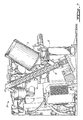
- FIGS. 1 and 2 illustrate an example embodiment of a [removable or] detachable valved lid element for a particulate storage combination or assembly 1 (i.e. cartridge) in accordance with the present invention; an example case element 3 is also shown.
- Figure 1 shows the a particulate storage assembly 1 in assembled format whereas figure 2 is an exploded view of the particulate storage assembly 1 exposing various parts of the particulate storage assembly, in particular of the lid element 5 and the opening 7 of the case element 3.
- the case element 3 as shown has a rigid wall structure surrounding the opening 7.
- the case element3 and the lid element 5 may be configured in any suitable manner such that the lid element 5 is removably attached(able) to the case element 3 so as to cover the opening 7 and thus form an enclosed space (e.g. chamber) for containing a particulate substance (not shown); the particulate substance may for example be a particulate milk substance such as for example powdered milk.
- the removable attachment is accomplished by configuring the lid element 5 and peripheral wall surrounding the opening 7 for a manually detachable press-fit, i.e. the case element and the lid element may be attached and detached by hand.
- the lid element5 is provided with a peripheral ring band 9 which has an inner diameter slightly smaller than the outer diameter of the peripheral wall surrounding the opening 7 of the case element 3. These diameters are selected relative to each other such that the lid element 5 may be manually pressed into (friction) engagement with the peripheral wall surrounding the opening 7 of the case element, 3 i.e. so as to close off the opening 7.
- the peripheral ring band 9 is provided with a plurality of spaced apart slots or cuts (one of which designated by the reference numeral 11. These slots facilitate a predetermined degree of expansion of the peripheral ring band 9 when the ring band 9 is forced to (frictionally) engage the peripheral wall surrounding the opening 7 of the case element 3.
- the lid element may be a screw-on lid element.
- the inner surface of the ring band may be provided with screw-like threads for mating engagement of corresponding screw-like threads on the outer surface of the peripheral wall surrounding the opening of the case element.
- any other type of attachment mechanism may be used to attache the lid element to the case element keeping in mind that the lid element must close of the opening and is to be detachably fixed to the case element.
- the particulate storage assembly may, for example, be used to contain a particulate substance for the preparation of a beverage (e.g. such as a coffee beverage); the particulate substance may be soluble or dispersable in water; it may, for example, be a powdered instant coffee material, a powdered instant milk or milk like material, powdered coco, or the like.
- a beverage e.g. such as a coffee beverage
- the particulate substance may be soluble or dispersable in water; it may, for example, be a powdered instant coffee material, a powdered instant milk or milk like material, powdered coco, or the like.
- the entire particulate storage assembly may be reused or alternatively only the lid element 5 may be reused.
- the lid element 5 may be removed from the case element 3, the case element 3 may be refilled with particulate substance and the lid element 5 placed back on the case element 3.
- the lid element 5 may be removed from the empty case element 3 and then be attached to a fresh case element 3 having particulate substance therein.
- a plurality of such fresh case elements may be stored for sequential use; each stored case element may be associated with any type of removable lid for closing of the opening during storage; the lid may be for example any type of (known) (e.g. flexible) manually (i.e. by hand) pull or rip off lid.
- the lid element has a wall member 13 extending from the peripheral ring band 9 and is provided with a valve member 15.
- the valve member illustrated has the form of a valved spout member; however the valve member may take on any other desired or necessary form keeping in mind its purpose as described herein.
- the valved spout member extends from the wall member 13 in an off-center like fashion.
- the valve member 14 has a hollow open ended cylindrical extension 17 which defines a channel 19 for providing a flow path for the flow of particulate substance or material out of the enclosed space as defined by the lid element 5 attached to the case element 3.
- One open end of the cylindrical extension 17 is attached to the wall member 13 and the other distal open end thereof is closed off by a removable cap 21.
- the cap 21 as illustrated is attached to the end of the cylindrical extension by a pin/slot combination; the pin 23 being attached to the cylindrical extension17, the L-shaped slot 25 being defmed by the peripheral wall of the cap 21 ; the long part (or root part) of the slot at one has an opening at the periphery of the cap whereas the shorter part (or foot part) extends perpendicularly from the longer part at the other end of the long part of the slot .
- the pin/slot combination is shown two or more may be used. Attachment is accomplished by passing the pin 23 through the root part of the L-shaped slot 25 and then turning the cap so as to lodge the pin in the foot of the L-shaped slot. Any other suitable (known) type of attachment may of course be used e.g. screw type attachment.
- the cap may be more or less permanently fixed to the cylindrical extension as by an adhesive or glue.
- the cap 21 has a blockable opening or outflow aperture 27 (seee figure 2 ) for providing an outlet for the flow of particulate substance or material out of the channel as defined by the cylindrical extension 17.
- the outflow aperture 27 is blockable by a spring biased plug element 29.
- the plug element 29 as shown in figure 1 is biased in a closed position so as to block off the outflow aperture 27.
- the plug element 29 is biased by a bias component which comprises a coil spring element 31 and a spring support element 33.
- the spring support element has a circular perforated base plate member 35 from which extends a stubby spring support projection 37; the perforations of the base plate member are sized and configured so as to allow the flow of particulate substance therethrough.
- the inner surface of the cylindrical extension 17 is provided with an inwardly extending ridge member (hidden from view) which may take the form of an annular like ring for seating or engaging the periphery of the circular perforated base plate member 35.
- the coiled spring element 31 is disposed about the stubby support projection 37 such that one end thereof abuts the base plate member 35 and the other end is engaged in a cavity in the base of the plug element 29 (see figure 5 ).
- the plug element 29, spring element 31, and stubby projection 37 are disposed such that the plug element 29 may be urged to compress the spring element 31 (again see figure 5 ).
- the plug element 29 and the bias component are configured such that the plug element 29 is displacable between a closed position and an open position.
- the plug element 29 When the plug element is in the closed position (as shown in figure 1 ) the plug element 29 closes off the outflow aperture 27 whereby particulate material (e.g. powder) is unable to flow out of said enclosed space (e.g. chamber) through said outflow aperture 27.
- particulate material e.g. powder
- the plug element 29 when the plug element 29 is pushed or urged to compress the spring element 31, the plug element 29 is able to pass from the closed position to an open position such that when the plug element is in said open position particulate material (e.g. powder) is able to flow out of said enclosed space (e.g. chamber) through said outflow aperture (see figure 10 ).
- the example embodiment of the lid element shown in figures 1 and 2 is also provided with a guide projection or tab 39 which may be used to orient the storage assembly with respect to components of a particulate conveying assembly as shown in figure 5 , 6 , 7 , and 13 and as shall be described below.
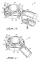
- FIG. 3 to 7 these figures illustrate an example embodiment of a conveyance system or assembly for conveying (or dispensing) particulate substance or material from a removeable storage combination such as described herein (e.g. for conveyance to a predetermined location or station such as a mixing station 40 - see for example figure 6 and 7 ).
- the assembly for conveying (or dispensing) particulate substance comprises a particulate delivery component 41 which comprises a conveyor element 43, and an interconnect element 45; if desired or necessary the assembly for conveying (or dispensing) particulate substance may also include a valve plug interaction element (as shown in figures 8, 9 and 10 ).
- FIG 4 this figure illustrates in exploded view a conveyor element 43 for conveying particulate substance from a replaceable particulate storage component to a chute 47.
- This figures also illustrates the interconnect element 45 for releasably interconnecting the conveyor element 43 and the outflow aperture of a replaceable particulate storage component (such as for example described herein) for the flow of particulate substance through the outflow aperture thereof to the conveyor element 43.
- the illustrated conveyor element 43 takes the form of an Archimedes screw type conveyor and thus has a broad-threaded screw member 49 encased in a hollow open-ended cylinder member (one half of which is designated by the reference numeral 51).
- the lower end of the screw member 49 is mechanically coupled by a gearing mechanism (not shown) to an electric motor 53 such that when the motor 53 is electrically energized rotation of the motor 53 induces a corresponding rotation of the screw member 49 in a rotational direction for urging particulate material to flow upwardly towards the distal end 55of the conveyor element; the motor may be mechanically coupled to the screw member in any suitable (known) manner.
- the distal end 55 of the conveyor element is provided with the particulate chute member 47 for directing the particulate substance to a desired location or station.
- the distal end of the conveyor element may also as desired include a particulate sensing component (indicated generally at 57) for sensing the absence of particulate material at the distal end of the conveyor element.
- the particulate sensing component may be configured in any suitable manner so as to generate a signal indicative of absence of particulate material. Such signal may for example be directed (not shown) to a solenoid switch component which may be configured to energize the motor in response to the presence of such signal (i.e.
- the signal may be directed to a controller element such as for example an electronic computer element comprising a suitable configured microprocessor
- the other lower end may alternatively or additionally, if so desired, be provided with a similar particulate sensing component (indicated generally at 59).
- This lower particulate sensing component may be used to generate a signal indicative that the storage component is empty of particulate substance and/or block energization of the motor 53 and illuminate a signal light indicative that the storage component needs to be replaced
- the interconnect element 45 is also disposed at the lower end of the conveyor element.
- the interconnect element 45 has a hollow cone member 61 and a tube member 63 which extends from the apex thereof.
- the tube member 63 communicates with the interior of the lower end of the hollow open-ended cylinder member of the conveyor element, i.e. the interconnect element has the general form of a funnel member (see figure 5 ).
- the hollow cone member 61 is configured to matingly engage the correspondingly shaped cap of the spout valve of the storage combination shown in figures 5 and 7 .
- valve plug interaction element 65 for releasably maintaining (i.e. for urging) the plug element 29 in an open position (i.e. against the bias component).
- the valve plug interaction element is disposed in the hollow cone member 61 of the interconnect element.
- the valve plug interaction element 65 has a circular perforated base plate member 67 from which extends a plug engagement projection 69; the perforations 71 of the base plate member 67 are sized and configured so as to allow the flow of particulate substance therethrough.
- the base plate member 67 may be integral with (e.g.
- the plug engagement projection 69 may be used to act against the plug 29 so as to induce compression of the associated coil bias spring and place the plug 29 in an open position as described herein, i.e. for the free flow of particulate substance in the direction of the show arrows.
- valve plug interaction element 65a as shown in the figures may alternatively be connected directly to or be integral with the plug 29 itself as shown in figure 11 , i.e. the valve plug interaction element (also generally designated 65 in figure 11 ) may be part of the lid element shown in figure 11 .
- valve plug interaction element may only comprise the circular perforated base plate member.
- the plug 29 of the storage combination may include a plug extension member 29a which may serve the same function of the plug engagement projection, i.e. the circular perforated base plate member may have a member for engaging the plug extension (see figure 12 ) so that it in turn induces the plug to compress the coil bias spring.
- a conveyance assembly for conveying (or dispensing) particulate substance in accordance with the present invention may further comprise a support component.
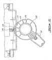
- FIG. 13 and 14 these figures illustrate an example of a support component configured for releasably engaging a removeable storage assembly or component as described herein such that the storage component 1 is oriented (during removal of particulate substance therefrom) so that the valved wall member 13 at least partially forms the bottom of the so engaged storage component 1 (i.e. for the free flow (i.e. gravity induced flow) of particulate substance from the enclosed space).
- the support component1 comprises a cartridge well for receiving the storage assembly, lid element head first.
- the cartridge well has a wall member 71 and a base member 73 (see figure 14 ).
- the base member 73 is disposed at an angle to the horizontal such that it may engage the lid element 5 so that the lid element 5 is also disposed at similar angle, i.e. the lid element thus forming part of the bottom of the storage assembly.
- the valve member 15 extend through an opening in the base member 73
- the base member 73 may be disposed so that it is essentially horizontal and engages the lid element so that the lid element is also disposed essentially horizontally, i.e. the lid element essentially becomes the bottom of the storage component during use.
- the illustrated cartridge well has a guide slot 75 for sliding and matingly engaging the previously mentioned guide projection or tab 39 for assuring proper orientation of the spout valve with respect to the interconnect element as the storage combination or component is placed into the cartridge well.
- a beverage selection system for an automatic beverage machine for dispensing a beverage selectable from a plurality of beverage types (or varieties) may comprising a configuration controller component, a plurality of switch elements, and a switch selection element.
- FIG 15 this figure schematically illustrate an example embodiment of a beverage selection system in accordance with the present invention.
- the system shown has a switch selection element indicated generally at 79 which comprises an infrared reflection member 81 disposed on an elongated support member 83.
- the system also has four switch configuration elements 85, 87, 89, and disposed on a second support member 93 above the selection element 79.
- the reflection member 81 may for example, be of a mirror like material whereas the support member depending on the form which the support member takes may be of an suitable infrared non-reflective material.
- the support member has the elongated form shown in figure 15 for a push-pull type displacement (as described below) wherein a portion of the surface of the support member 83 uncovered by a reflection member may alone be disposed so as to be exposed opposite a switch configuration element, the support member 83 in such area may be of a non-reflective material; on the other hand, if the reflection member is disposed on a projection which extends radially outward from a rotary type support member (as discussed below) it may be of any suitable material since the system may be configured such that only the reflection member will be disposed opposite a switch configuration element and not a support member surface alone.
- Each of the switch configuration elements 85, 87, 89, and 91 comprises an infrared detection component comprising an infrared emitter means 93 for providing infrared for reflection from said infrared reflection member 81 as reflected infrared, and an infrared detector means 95 for detecting said reflected infrared from said infrared reflection member.
- the switch elements may comprise any suitable(known) emitters and detectors.
- Each of said switch elements is configured to pass from a first state to a second state in response to detection of said reflected infrared and to pass from said second state to said first state in response to the non-detection of said infrared reflected infrared; i.e. the second state is maintained for the duration of the detected reflected light.
- a switch configuration element may be able to pass from a first voltage state to a second voltage state.
- the switch configuration elements may include a signal generator component (as shown) which is able to generate a more complex configuration signal (i.e. electrical signal) in response to the detection of reflected infrared (i.e. second state); no such complex configuration signal being generated when the switch element is in the first state.
- the switch configuration elements may in any event take on any suitable (known) form provided that they function as described above, i.e. provide detectable first and second states.
- the configuration controller component 97 may for example comprise an electronic computer element (e.g. comprising a microprocessor), appropriate software (i.e. programing instructions), interconnections between the computer element and the beverage preparation elements, etc..).
- the configuration controller component 97 is in any event set up so as to be able (i.e. configured ) to recognize (i.e. detect) when a switch element is in said second state (e.g. by the presence of a configuration signal, the surpassing of a threshold voltage, etc.) and so as to be able to initiate the configuration of the beverage machine for (i.e. uniquely) dispensing the beverage type associated with such switch element.
- the configuration controller component may for example comprise a microprocessor which compares values corresponding to the second states with values stored in a table of values and then determines an appropriate output reaction for configuring the beverage machine for the preparation of a specific.
- the configuration controller component 97 is shown by way of example as being able to selectively initialize the appropriate beverage preparation elements of the beverage machine for the preparation of four beverage types; each of the blocks notionally groups together those beverage preparation elements appropriate for the preparation of a specific beverage.
- switch configuration element 87 is shown as being in the second state due to reflected infrared (see arrows); this second state may be recognizable by the configuration controller component 97 as designating a choice for cappuccino and thus the configuration controller component 97 would set itself up to initiate a beverage preparation cycle using the necessary elements of the coffee machine for the preparation of cappuccino; the preparation cycle commencing once a start brew button (not shown) connected to the configuration controller component 97 signals the configuration controller component 97 to make available to the necessary preparation elements the necessary operation energy (e.g. electricity), from an energy source (not shown), in accordance with the chosen beverage preparation cycle.
- the necessary operation energy e.g. electricity
- beverage preparation elements may for example be selected for among the following nonlimiting list of elements:
- the infrared reflection member 81 is disposed on the elongated support member 83 which is displaceable in a push-pull type manner in the direction of the arrows 101 and 103 whereas the infrared detection components are fixed relative to the reflection member 81, i.e. the reflection member is induced to move rather than the infrared detection components.
- the infrared detection components may be displaceable and the reflection member may be fixed.
- both the reflection member and the infrared detection components may be displaceable. I n any event, such displacement is to be carried out keeping in mind the purpose of the selection system, namely, to result in the ability to selectively configure a beverage machine for the preparation of a desired beverage type from among a class or group of beverage types.
- the switch selection element 79 also includes an elongated hollow sleeve member 105.
- the elongated support member and reflection member are disposed in the elongated hollow sleeve member for sliding displacement thereof in the sleeve member.
- the upper wall of the hollow sleeve member is provided, at predetermined locations, with exposure openings 107, 109, 111, and 113. These exposure openings are each disposed opposite a respective switch element so as to provide an exposure window for exposing the reflection member 81 opposite the respective switch element; i.e. to allow infrared from the switch element to be reflected back thereto for detection.
- Each of the exposure windows is associated with a respective releasable locking mechanism for releasably locking the support member in position so that the reflection member is in the exposure window.
- the switch selection element and the switch configuration elements are configured and disposed so that the light reflection member is displaceable between releasably lockable positions such that each such lockable position associates the light reflection member with the light detection component of a respective switch element.
- the illustrated example releasable locking mechanism comprises a cavity element 115 associated with the hollow sleeve member 105 .
- a portion of a ball bearing 117 is able to extend out of a cavity opening communicating with the interior of the hollow sleeve from below an associated upper window opening; the cavity opening is smaller than the ball bearing 117 such that the ball bearing may not pass therethrough into the hollow sleeve member.
- the cavity element includes a coiled bias spring 119 which at one end pushes on the ball bearing and at the other end engages the bottom of the cavity. A sufficient force pushing down on the ball bearing will compress the coil spring allowing the ball bearing to be pushed into the cavity clear of the cavity opening.
- the elongated support member has an indentation or cavity 121 for matingly engaging the portion of the ball bearing 117 extending out of the cavity opening so as to releasably lock the elongated support member in place.
- the cavity of the elongated support member is configured such that the application of sufficient predetermined force in the direction of one of the arrows 101 and 103 will cause the peripheral edge of the cavity of the elongated support member to slide over the ball bearing to urge the ball bearing into the associated cavity element compressing the bias coil spring so as to allow the elongated support member to slide on to the next releasable locking mechanism.
- the rotary selection element 121 comprises an annular or ring shaped support member 123 for support of the reflection member 125.
- the reflection member 125 is disposed on a finger-like projection 127 which extends radially outward from an upper part of the ring-like support member 123.
- the ring shaped support member 123 is associated with an annular groove element 129.
- the bottom of the groove element is defined by the outer surface 131 of the ring shaped support member 123.
- the groove element is also defined by opposed side walls defined on the one hand by a lower ring projection 133 extending radially outward from the bottom part of the ring-like support member and a plurality of radially spaced apart and extending projections (designated 135) disposed intermediate or between the finger-like projection 127 and the above mentioned lower ring projection 133.
- the opposed side walls are spaced apart so as to be able to slidingly engage the curved or arched side edge of a projection member defined by a housing support as shall be described below (see figure 18 and 19 ); the so engaged rotary member is able to rotate about the central longitudinal axis of the ring shaped support member form one releasably lockable position to another.
- the rotary selection element also has a handle member 141 which is pivotably displaceable between a position more or less in the plane of the ring shaped support member (see figure 19 ) and a position which is at an angle to the plane of the ring shaped support member (see figure 17 ).
- the handle member has projection members 143 and 145 configured for a friction fit with side grooves 147 and 148 of the lower ring projection as well as elements 149 and 151 four sleeve or collar engagement of pivot pin projections (one of which designated by the reference number 153 in figure 16 ) extending from both sides of the central finger member disposed between the grooves.
- FIG 19 the rotary selection element 121 is shown in place with the opposed side walls of the groove element slidingly engaging the curved or arched side edge of the projection member 155 .
- the rotary selection element is secured in place by a clamp element 157 (see figure 18 ) having two screw openings for receiving screws 159 for screw engagement with respective screw attachement openings defined by the housing support (one of which is designated by hte refernce numeral 161).
- the inner surface of the clamp element 157 may be configured to slidingly engage the extending projections 135.
- the outer surface of the clamp 157 may be provided with symbols (not shown) indicative of a beverage type, the symbols being disposed so as to be associated with a releasable locking position of the rotary selection element; the handle having a pointer projection 163 pointing to a symbol when the rotary selection element is in a locking position.
- the so disposed rotary selection element is displaceable about a horizontally extending axis 165 (see figure 19 ) of rotation co-incident with the longitudinal axis of the ring shaped support member 123 between a plurality of releasably lockable rotary positions, each such lockable rotary position being associated with a respective switch element
- the reflection member 125 may be made travel through a curved or arched trajectory.
- the housing support also supports an electronic selection board 167 on the underside of which is disposed four infrared emitter/detector combinations for four respective switch configuration elements (one of which is designated by the reference number 169 in figure 23 ).
- the infrared emitter/detector combinations are disposed about a curve or a arched pathway located just above the arched trajectory of the reflection member.
- each configuration switch element of the rotary selection system comprises a light detection component comprising a light emitter means for providing a light pulse, a light detector means for detecting reflected light and a signal generation means for generating an activation electrical signal in response to detected reflected light whereby a switch element passes to and is maintained in said active configuration for the duration that reflected light is detected; the light may for example be infrared light.
- the electronic selection board also includes elements of the configuration controller component.
- the rotary selection element may also be releasably locked into discrete positions whereby the reflection member thereof is associated with the light (e.g. infrared) detection component of a respective switch element.
- the locking system for the rotary selection element is analogous to the releasable locking mechanism shown in figure 15 , for the push-pull type selector,.
- the lower ring projection 133 extending radially outward from the bottom part of the ring-like support member 123 has a rear surface which is contoured so as to have a plurality of intersecting curved surfaces (e.g. camming like surfaces). The curved surfaces intersect so as to define features which are slot like (ne of which ar designated by the reference number 171).
- the releasable locking mechanism also a cavity associated with a pin member 173 which is biased, by a spring member 175 in the cavity, to be in an extended position.
- the engagement end of the pin member has an engagement surface suitably shaped such that manual rotation of the rotary selector element will cause the pin member 173 to ride up and over the curved surface in the direction of travel (see figure 20 ); this action will push the pin member 173 into the associated cavity allowing the reflection member 125 to be carried to another discrete position.
- the reflection member 125 When locked in a discrete position, the reflection member 125 is disposed opposite a predetermined configuration switch element 169 ( figure 23 ), the switch element in turn being associated by the configuration controller component, to which it is connected, with beverage machine configuration for the preparation of a specific beverage.
- the illustrated rotary selection system is set up such that the light reflection member 125 thereof is displaceable about a horizontally extending axis of rotation 153 (i.e, for travel of the reflection member 125 over a curved band or trajectory) relative to the light (infrared) detection components between a plurality of releasably lockable (rotary) positions, each such lockable (rotary) position being associated with a respective switch element.
- the rotary selection element may be disposed adjacent the dispensing station with the outlets of the fluid conduits extending from a dispenser station sleeve 177 (i.e. from the coffee extraction station, hot water component, milk preparation station, etc.) disposed in the annular opening defined by the rotary selection element.
- the outlet for the coffee is shown as element 179.
- the beverage machine may also be provided with a separate starting contact for (electrical) energization of the beverage machine, the starting contact being suitably connected to a power source.
- the starting contact may comprise a push button switch element for this purpose.
- the push button may be pushed in so as to triggers or initiates the preparation cycle of the beverage variety selected.
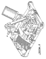
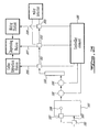
- FIG 25 this figure schematically illustrates an example of a hot water dispenser assembly (or system) in accordance with the present invention which may for example be associated or incorporated into a coffee beverage making machine.
- the hot water dispenser system comprises an example valve assembly, a hot water component for producing hot water, and a fluid conduit component providing fluid communication between the hot water component and the valve assembly.
- the illustrated hot water dispenser system has a water holding tank or reservoir 181 which may be filled manually through an opening in the top of the tank.
- the tank 181 may also be filled via a water line or pipe 183 connected to a suitable source of water (e.g. municipal water system).
- the water pipe 183 is connected to the municipal water line via a solenoid valve element 185
- the solenoid valve element 185 is able to pass between an energized and non-energised state; in the energized state an electrical current is applied to the solenoid valve whereas in the non-energized state no current is so applied.
- the solenoid valve 181 When the solenoid valve element 185 is in the non-energized state it closes off water communication to the tank 181; when the solenoid valve element 185 is in the energized state it opens water communication to the tank 181.
- the solenoid valve 181 is controlled by a float switch mechanism 187 associated with the tank.
- the float switch mechanism187 may be any (known) type of float switch mechanism which is configured to energize or de-energize the solenoid valve in response to the rise and fall of a float 189 in the tank, e.g. the solenoid 185 being energized when the float passes below a predetermined height level in the tank.
- the hot water system shown includes a pump 191 for the displacement of water from the holding tank 181 to an (electrical) hot water heater 193 through a flow meter element 195.
- the flow meter 195 is configured in any suitable (known) fashion to generate a (electric) signal indicative of the amount of water being sent to the water heater, the signal being sent to an electronic controller element 199 which is configured in any suitable manner to selectively choose, initiate as well as stop a predetermined hot water dispensing cycle (i.e. control pump activity).
- the illustrated hot water dispensing system shown in figure 25 has a multi-way valve assembly comprising three selectively operable solenoid valves, 201, 202 and 203 the valves being selectively operable by the electronic controller element 199.
- the first two valves 201 and 202 each have a single inlet port but two outlet ports; one outlet port is for communication with the next upstream valve and the other for communication with the associated station (see below).
- the active outlet port i.e. open port
- the third valve 203 has an inlet port and a single outlet port. Thus as shown the valves are connected in series to each other.
- Each solenoid valve is configure and disposed so as to control the flow of hot water from the hot water heater through a respective conduit branch 205, 207 and 209 to one of three predetermined stations, namely a brewing station, discharge station, and a mixing station; the brewing station and a mixing station are in fluid communication with the discharge station (see for example figure 24 ) .
- a brewing station may take on any suitable (known) form, and may for example include a coffee extraction device comprising an extraction chamber in which may be disposed (e.g. manually) a coffee tablet and configured to be fed with heated water from the heater, and from which, following an extraction operation, brewed coffee flows to the dispensing station into a receptacle; for examples of such devices please see PCT international publication nos. WO 00/44268 , WO 00/38558 and WO 00/64318 .
- a mixing station may include a mixing chamber such as shown in figure 26 to 28 for mixing hot water with a milk powder substance.
- the milk powder may, for example be delivered to the mixing chamber by a conveyance assembly as described herein.
- the hydrated milk powder may be sent or conveyed to a downstream chamber 210 (se figure 28 ) for foaming of the aqueous milk material and then be conveyed by suitable conduit means 212 (see figure 28 ) to the dispensing station.
- a dispensing station may comprise a support for a beverage receptacle (receptacle not shown), having disposed above such receptacle support a number of outlets of fluid conduits for respectively delivering hot coffee, hot (whipped) milk substance, hot water, etc. to a beverage receptacle (e.g. cup); e.g. the dispensing station may comprise a drainage outlet tube from the brewing chamber or from a whipped milk station, the tube having a lower end for discharging a brewed beverage, milk, etc. therefrom.
- a beverage receptacle e.g. cup
- the dispensing station may comprise a drainage outlet tube from the brewing chamber or from a whipped milk station, the tube having a lower end for discharging a brewed beverage, milk, etc. therefrom.
- FIG 24 and 26 A possible type of dispensing station is shown in figure 24 and 26 , the support for the receptacle being shown in figure 26 just below the selection element 121
- the rotary selection element 121 may be disposed adjacent the dispensing station with the outlets of the fluid conduits disposed in the annular opening defined by the rotary selection element (see figure 24 ).
- a predetermined hot water dispensing cycle as controlled by the electronic controller element thus comprises energization of the pump for the displacement of water from the hot water heater through a selected valve of said valve assembly to a predetermined station.
- the three valves may be selectively controlled by the controller element 199; thus for example when valve 201 is energised, so as to establish a fluid connection with the brewing station, there is no fluid communication between the other valves and their respective stations; vice-versa for the other valves.
- controller element 199 for example when valve 201 is energised, so as to establish a fluid connection with the brewing station, there is no fluid communication between the other valves and their respective stations; vice-versa for the other valves.
- the hot water dispenser assembly comprises a fluid conduit component comprising a plurality of conduit element for fluid communication between the hot water heater and each of the valves.
- the hot water dispenser assembly may also if so desired or needed include a malfunction sensing component for sensing the absence of water in the fluid conduit component (i.e. lack of water being indicative of a malfunction in the hot water system i.e. indicative of lack of sufficient water in heater and/or pump due to a water leak etc.) signal.
- a malfunction sensing component for sensing the absence of water in the fluid conduit component (i.e. lack of water being indicative of a malfunction in the hot water system i.e. indicative of lack of sufficient water in heater and/or pump due to a water leak etc.) signal.
- the conduit elements are of a plastic type material which is a non-conductor of electricity.
- the body of the valves are metallic and thus are electrically. conductive.
- the body of valve and of valve are connected to a water detector which comprises a signal generator; the generator may be of any suitable (known) type keeping in mind its function.
- the water present in the conduit between the valves acts as a signal conductor such that if no water is present the signal link between the valves will be broken.
- the water detector also includes a signal detection element configured (in any suitable way) to detect the absence such signal and in such case generate a further (electric) signal indicative of the absence of water, this further signal being sent to an LED so as to alert the user of the assembly; alternatively the further signal may be sent to the controller means to disconnect the pump and electric heater form the power source since the operation of these elements in the absence of water could lead to their damage.
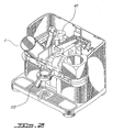
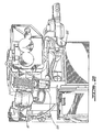
- a beverage machine may as mentioned if desired incorporate one or more of the systems or parts thereof as described herein. Please see for example figures 26 and 27 wherein an example combination is shown wherein like reference numbers have been used to designate like elements mentioned with respect to the previous figures.
Landscapes
- Engineering & Computer Science (AREA)
- Food Science & Technology (AREA)
- Apparatus For Making Beverages (AREA)
- Devices For Dispensing Beverages (AREA)
- Beverage Vending Machines With Cups, And Gas Or Electricity Vending Machines (AREA)
- Tea And Coffee (AREA)
- Non-Alcoholic Beverages (AREA)
- Separation By Low-Temperature Treatments (AREA)
- Cyclones (AREA)
- Separation Using Semi-Permeable Membranes (AREA)
Claims (10)
- Getränkemaschine zum Ausgeben eines Getränks, wobei die Getränkemaschine folgendes aufweist:eine Mischstation,eine Ausgabestation,eine Lieferkomponente für partikelförmige Substanzen, undein Zuflussmittel für wässrige Medien zum Liefern eines wässrigen Mediums an die Mischstation,wobei die Mischstation mit der Ausgabestation kommuniziert und die Lieferkomponente für partikelförmige Substanzen in der Lage ist, eine partikelförmige Substanz aus einer entnehmbaren Speicherkomponente für partikelförmige Substanzen an die Mischstation zu liefern,
wobei die entnehmbare Speicherkomponente für partikelförmige Substanzen ein mit einem Ventil versehenes Wandelement aufweist und so ausgestaltet ist, dass sie einen abgeschlossenen Raum zum Aufnehmen einer partikelförmigen Substanz definiert,
wobei das mit einem Ventil versehene Wandelement ein Ventilglied aufweist, welches eine Austrittsöffnung zum Bereitstellen eines Fließwegs für den Fluss der partikelförmigen Substanz aus dem abgeschlossenen Raum heraus definiert, wobei das Ventilglied ferner ein Verschlusselement und ein Ausrichtungselement aufweist, wobei das Verschluss- und das Ausrichtungselement so konfiguriert sind, dass das Verschlusselement zwischen einer geschlossenen Position und einer offenen Position verlagerbar ist, wobei, wenn das Verschlusselement in der geschlossenen Position ist, das Verschlusselement die Austrittsöffnung verschließt, wobei die partikelförmige Substanz daran gehindert ist, aus dem abgeschlossenen Raum durch die Austrittsöffnung zu fließen, und, wenn das Verschlusselement in der geöffneten Position ist, die partikelförmige Substanz mithilfe der Schwerkraft aus dem abgeschlossenen Raum durch die Austrittsöffnung fließen kann, wobei das Ausrichtungselement das Verschlusselement in die geschlossene Position ausrichtet,
dadurch gekennzeichnet, dass
die Getränkemaschine ein Fördersystem aufweist, wobei das Fördersystem eine Haltekomponente und die Lieferkomponente für partikelförmige Substanzen aufweist,
die Haltekomponente derart ausgestaltet ist, dass sie die entnehmbare Speicherkomponente für partikelförmige Substanzen lösbar aufnimmt, so dass die entnehmbare Speicherkomponente für partikelförmige Substanzen derart orientiert ist, dass das mit einem Ventil versehene Wandelement wenigstens teilweise den Boden der so aufgenommenen entnehmbaren Speicherkomponente für partikelförmige Substanzen für einen schwerkraftbedingten Fluss der partikelförmigen Substanz aus dem abgeschlossenen Raum durch die Ausflussöffnung bildet,
die Lieferkomponente für partikelförmige Substanzen ein Zuführelement zum Zuführen der partikelförmigen Substanz von der entnehmbaren Speicherkomponente für partikelförmige Substanzen an die Mischstation aufweist, wobei die Lieferkomponente für partikelförmige Substanzen ferner ein Zwischenverbindungselement zum lösbaren Zwischenverbinden des Zuführelements und der Austrittsöffnung des Ventilglieds für den schwerkraftbedingten Fluss der partikelförmigen Substanz durch die Austrittsöffnung an das Förderelement aufweist, und dass
die Lieferkomponente für partikelförmige Substanzen ein Ventilverschlussinteraktionselement zum lösbaren Hineindrängen des Verschlusselements des Ventilglieds in die geöffnete Position für den schwerkraftbedingten Fluss der partikelförmigen Substanz aus dem abgeschlossenen Raum an das Förderelement, wenn die entnehmbare Speicherkomponente für partikelförmige Substanzen von der Haltekomponente aufgenommen ist, aufweist. - Getränkemaschine nach Anspruch 1, dadurch gekennzeichnet, dass die Lieferkomponente für partikelförmige Substanzen die entnehmbare Speicherkomponente für partikelförmige Substanzen aufweist.
- Getränkemaschine nach Anspruch 2, dadurch gekennzeichnet, dass das Ventilverschlussinteraktionselement das Verschlusselement des Ventilglieds lösbar in der offenen Position hält.
- Getränkemaschine nach Anspruch 2, dadurch gekennzeichnet, dass das Verschlusselement das Ventilverschlussinteraktionselement aufweist, und dass das Ventilverschlussinteraktionselement das Verschlusselement des Ventilglieds lösbar in der geöffneten Position hält.
- Getränkemaschine nach Anspruch 1, dadurch gekennzeichnet, dass die Haltekomponente eine Halteaussparung zum Aufnehmen der entnehmbaren Speicherkomponente für partikelförmige Substanzen aufweist.
- Getränkemaschine nach einer der Ansprüche 2, 3 oder 4, dadurch gekennzeichnet, dass die Haltekomponente eine Halteaussparung zum Aufnehmen der entnehmbaren Speicherkomponente für partikelförmige Substanzen aufweist.
- Getränkemaschine nach Anspruch 1, dadurch gekennzeichnet, dass das Förderelement eine Förderschnecke aufweist.
- Getränkemaschine nach einer der Ansprüche 2, 3, 4 oder 6, dadurch gekennzeichnet, dass das Förderelement eine Förderschnecke aufweist.
- Getränkemaschine nach einer der Ansprüche 2, 3, 4, 6 oder 8, dadurch gekennzeichnet, dass die partikelförmige Substanz eine in Partikeln vorliegende Milchsubstanz ist.
- Getränkemaschine nach einer der Ansprüche 1, 2, 3, 4, 5, 6, 7, 8 oder 9, gekennzeichnet durch eine Kaffeeextraktionsstation, die mit der Ausgabestation kommuniziert.
Applications Claiming Priority (3)
| Application Number | Priority Date | Filing Date | Title |
|---|---|---|---|
| CA002411809A CA2411809C (en) | 2002-11-08 | 2002-11-08 | Systems useful for beverage making machines |
| CA2411809 | 2002-11-08 | ||
| PCT/CA2003/001718 WO2004041043A2 (en) | 2002-11-08 | 2003-11-10 | Systems useful for beverage making machines |
Publications (2)
| Publication Number | Publication Date |
|---|---|
| EP1558118A2 EP1558118A2 (de) | 2005-08-03 |
| EP1558118B1 true EP1558118B1 (de) | 2008-09-10 |
Family
ID=32304017
Family Applications (1)
| Application Number | Title | Priority Date | Filing Date |
|---|---|---|---|
| EP03773393A Expired - Lifetime EP1558118B1 (de) | 2002-11-08 | 2003-11-10 | Für getränkemaschine geeignetes system |
Country Status (8)
| Country | Link |
|---|---|
| US (4) | US20040149136A1 (de) |
| EP (1) | EP1558118B1 (de) |
| JP (1) | JP4343842B2 (de) |
| AT (1) | ATE407612T1 (de) |
| AU (1) | AU2003281879A1 (de) |
| CA (2) | CA2660302C (de) |
| DE (1) | DE60323527D1 (de) |
| WO (1) | WO2004041043A2 (de) |
Cited By (1)
| Publication number | Priority date | Publication date | Assignee | Title |
|---|---|---|---|---|
| US8043645B2 (en) | 2008-07-09 | 2011-10-25 | Starbucks Corporation | Method of making beverages with enhanced flavors and aromas |
Families Citing this family (23)
| Publication number | Priority date | Publication date | Assignee | Title |
|---|---|---|---|---|
| GB0316778D0 (en) * | 2003-07-17 | 2003-08-20 | Mars Inc | Semi-automatic beverage making apparatus |
| JP2006260429A (ja) * | 2005-03-18 | 2006-09-28 | Sanden Corp | 飲料自動販売機の飲料調合方法及び飲料自動販売機 |
| DE202006008409U1 (de) * | 2006-05-27 | 2006-08-10 | Eugster/Frismag Ag | Einrichtung zum selbsttätigen Auflösen von Instantpulver, insbesondere Milchpulver, in heißem Wasser und insbesondere zum Aufschäumen |
| FR2902303B1 (fr) * | 2006-06-15 | 2013-07-12 | Seb Sa | Distributeur de produit pulverulent a reservoir amovible |
| ITMI20061469A1 (it) * | 2006-07-26 | 2008-01-27 | De Longhi Spa | Dispositivo per la formazione di sc hiuma in una bevanda a base di latte |
| CA2667383C (en) | 2006-10-24 | 2014-09-09 | A.C. Dispensing Equipment, Inc. | Auger-driven powder dispenser |
| US8820214B2 (en) * | 2007-01-04 | 2014-09-02 | The Coca-Cola Company | System and method for producing foamed milk from powder |
| US9394153B2 (en) | 2007-03-15 | 2016-07-19 | The Coca-Cola Company | Multiple stream filling system |
| CN101657130B (zh) * | 2007-04-16 | 2013-12-11 | 皇家飞利浦电子股份有限公司 | 用于产生饮料的装置和该装置的用途 |
| US7802514B2 (en) * | 2007-06-05 | 2010-09-28 | Uni-Splendor Corp. | Locking structure of hot beverage machine with steam sealing device |
| DE202007008815U1 (de) * | 2007-06-21 | 2007-11-29 | Mahlich, Gotthard | Mehrportionbehälter für pulverförmige Getränkebasisstoffe |
| EP2008554A1 (de) * | 2007-06-28 | 2008-12-31 | Nestec S.A. | System zur Lagerung und Dosierung eines Pulvers |
| EP2203907A2 (de) * | 2007-09-06 | 2010-07-07 | The Coca-Cola Company | Verfahren zur steuerung mehrerer abgeber |
| US8161865B2 (en) * | 2008-05-13 | 2012-04-24 | Fluid Management Operations, Llc | Modular flavor dispenser for use with food or beverage machines |
| EP2123201B1 (de) * | 2008-05-22 | 2013-07-10 | Gruppo Cimbali S.p.A. | Automatischer Getränkespender mit verbesserter Abgabevorrichtung |
| GB0818884D0 (en) * | 2008-10-15 | 2008-11-19 | Nestec Sa | Food processing apparatus and method |
| US8328411B2 (en) * | 2008-11-21 | 2012-12-11 | Winberry Steven N | Beverage mixing apparatus |
| US8528466B2 (en) * | 2010-02-05 | 2013-09-10 | Bobbi J Sweet | Liquid overflow platform and container for small appliances |
| EP2693923A1 (de) * | 2011-04-05 | 2014-02-12 | Nestec S.A. | Satz aus modularen getränkezubereitungsmaschinen und verfahren zur konfiguration und herstellung der maschinen |
| US9782034B2 (en) | 2015-10-30 | 2017-10-10 | A.C. Dispensing Equipment Inc. | Dispenser for granular material with a valve assembly |
| US10314435B2 (en) * | 2016-07-03 | 2019-06-11 | Geoff Hall | Steam driven dish warmer |
| US11219329B2 (en) | 2018-04-12 | 2022-01-11 | Marmon Foodservice Technologies, Inc. | Sugar dispenser with auger |
| CN111820738B (zh) * | 2019-04-19 | 2022-04-15 | 佛山市顺德区美的饮水机制造有限公司 | 饮水机 |
Family Cites Families (27)
| Publication number | Priority date | Publication date | Assignee | Title |
|---|---|---|---|---|
| US2183837A (en) * | 1936-04-28 | 1939-12-19 | Du Pont | Process and apparatus for extraction |
| US2911901A (en) * | 1956-09-25 | 1959-11-10 | Automatic Canteen Co | Coffee making apparatus |
| US3046856A (en) * | 1959-04-06 | 1962-07-31 | Baxter Orion Martin | Concrete finishing device |
| US3046869A (en) * | 1959-10-02 | 1962-07-31 | Robert Z Greene | Filter tape coffee brewer |
| US3072299A (en) * | 1960-06-17 | 1963-01-08 | Marc H Sessions | Dispenser for powdered soap and the like |
| US3586214A (en) * | 1969-01-21 | 1971-06-22 | Moyer Diebel Ltd | Dispensing machines with multiple selection |
| US3682090A (en) * | 1971-02-19 | 1972-08-08 | Coffee Corp Sa | Coffee bar machine |
| IT1060679B (it) * | 1976-08-06 | 1982-08-20 | Girolamo Silvestro Di | Apparecchio per l attuazione del ciclo completo di preparazione di bevanda calda frullata, ottenuta da polvere di caffe solubile o altri prodotti solubili |
| US4191101A (en) * | 1977-12-21 | 1980-03-04 | Toshiba Kikai Kabushiki Kaisha | Apparatus for preparing a cup of hot drink |
| IT1131540B (it) | 1980-06-10 | 1986-06-25 | Illycaffe Spa | Macchina da caffe' espresso che estrae il caffe' da cialde di caffe |
| DE3032054C2 (de) * | 1980-08-26 | 1986-07-03 | Heinz 7230 Schramberg Scheithauer | Vorrichtung zum Dosieren von Flüssigkeiten oder von halbflüssigen Stoffen |
| US4665808A (en) * | 1985-12-13 | 1987-05-19 | Wuerttembergische Metallwarenfabrik Ag. | Coffee percolator |
| NL8800548A (nl) | 1988-03-04 | 1989-10-02 | Koninklijke Olland Groep Bv | Drankenautomaat voor warme dranken. |
| US5133247A (en) * | 1991-01-11 | 1992-07-28 | Mr. Coffee, Inc. | Coffee maker |
| ATE162696T1 (de) | 1993-08-31 | 1998-02-15 | Juergen Pilger | Vorrichtung zum verpacken, zum transport und zum kontrolliert dosierten ausgeben einer körnigen oder pulverförmigen ware |
| FR2709655B1 (fr) | 1993-09-06 | 1995-11-24 | Cafes Cie Mediterraneenne | Machine à café express utilisant un conditionnement de café moulu du type pastille pré-dosée. |
| FR2713906B1 (fr) * | 1993-12-20 | 1996-08-30 | Moulinex Sa | Distributeur automatique de mouture. |
| US5421491A (en) * | 1994-03-07 | 1995-06-06 | Tuvim; Yuri | Measuring and dispensing device |
| US5957036A (en) * | 1998-10-16 | 1999-09-28 | Hamilton Beach/Proctor-Silex, Inc. | Coffee maker with a pause-serve mechanism |
| DE69807359T2 (de) | 1998-12-24 | 2003-04-17 | Compagnie Mediterraneenne Des Cafes, Carros | Brühkammer für einen automat zum zubereiten von heissen getränken |
| FR2788955B1 (fr) | 1999-01-28 | 2001-04-06 | Cie Mediterraneenne Des Cafes | Dispositif pour l'extraction de cafe |
| US6389948B1 (en) * | 1999-01-28 | 2002-05-21 | Heckler & Koch Gmbh | Ammunition feed device for beltless fed ammunition |
| PT1028068E (pt) * | 1999-02-12 | 2003-06-30 | Nestle Sa | Cartucho de recarga para dispositivo de distribuicao de bebidas e dispositivo adaptado a esse cartucho |
| FR2792813B1 (fr) | 1999-04-27 | 2001-06-29 | Cie Mediterraneenne Des Cafes | Dispositif et procede de commande de la fermeture et de l'ouverture d'une chambre d'extraction de machine a cafe |
| US6571686B1 (en) * | 2001-01-12 | 2003-06-03 | Sunbeam Products, Inc. | Brew basket with overflow channel |
| DE20100700U1 (de) * | 2001-01-16 | 2001-03-22 | Eugster/Frismag Ag, Romanshorn | Kaffeegetränkzubereitungsautomat, insbesondere Espressoautomat |
| US6450371B1 (en) * | 2002-01-24 | 2002-09-17 | Yury Sherman | Device for measuring, dispensing and storing of granular and powder materials |
-
2002
- 2002-11-08 CA CA2660302A patent/CA2660302C/en not_active Expired - Lifetime
- 2002-11-08 CA CA002411809A patent/CA2411809C/en not_active Expired - Lifetime
-
2003
- 2003-11-10 AT AT03773393T patent/ATE407612T1/de not_active IP Right Cessation
- 2003-11-10 AU AU2003281879A patent/AU2003281879A1/en not_active Abandoned
- 2003-11-10 JP JP2004548993A patent/JP4343842B2/ja not_active Expired - Lifetime
- 2003-11-10 WO PCT/CA2003/001718 patent/WO2004041043A2/en not_active Ceased
- 2003-11-10 EP EP03773393A patent/EP1558118B1/de not_active Expired - Lifetime
- 2003-11-10 DE DE60323527T patent/DE60323527D1/de not_active Expired - Lifetime
- 2003-11-10 US US10/705,411 patent/US20040149136A1/en not_active Abandoned
-
2006
- 2006-07-26 US US11/493,106 patent/US7441495B2/en not_active Expired - Lifetime
-
2007
- 2007-03-26 US US11/728,421 patent/US20080034977A1/en not_active Abandoned
-
2010
- 2010-05-14 US US12/780,474 patent/US20100219201A1/en not_active Abandoned
Cited By (11)
| Publication number | Priority date | Publication date | Assignee | Title |
|---|---|---|---|---|
| US8043645B2 (en) | 2008-07-09 | 2011-10-25 | Starbucks Corporation | Method of making beverages with enhanced flavors and aromas |
| US8114457B2 (en) | 2008-07-09 | 2012-02-14 | Starbucks Corporation | Methods of making beverages with enhanced flavors and aromas |
| US8114458B2 (en) | 2008-07-09 | 2012-02-14 | Starbucks Corporation | Methods of making beverages with enhanced flavors and aromas |
| US8114459B2 (en) | 2008-07-09 | 2012-02-14 | Starbucks Corporation | Methods of making beverages with enhanced flavors and aromas |
| US8414953B2 (en) | 2008-07-09 | 2013-04-09 | Starbucks Corporation | Beverages with enhanced flavors and aromas |
| US8524306B2 (en) | 2008-07-09 | 2013-09-03 | Starbucks Corporation | Beverages with enhanced flavors and aromas |
| US8535748B2 (en) | 2008-07-09 | 2013-09-17 | Starbucks Corporation | Beverages with enhanced flavors and aromas |
| US8541042B2 (en) | 2008-07-09 | 2013-09-24 | Starbucks Corporation | Beverages with enhanced flavors and aromas |
| US10154675B2 (en) | 2008-07-09 | 2018-12-18 | Starbucks Corporation | Soluble coffee products for producing beverages with enhanced flavors and aromas |
| US11160291B2 (en) | 2008-07-09 | 2021-11-02 | Starbucks Corporation | Soluble coffee products for producing beverages with enhanced flavors and aromas |
| US12207667B2 (en) | 2008-07-09 | 2025-01-28 | Starbucks Corporation | Soluble coffee products for producing beverages with enhanced flavors and aromas |
Also Published As
| Publication number | Publication date |
|---|---|
| WO2004041043A3 (en) | 2004-09-23 |
| US20060261085A1 (en) | 2006-11-23 |
| HK1079069A1 (en) | 2006-03-31 |
| US20080034977A1 (en) | 2008-02-14 |
| CA2660302A1 (en) | 2004-05-08 |
| US20040149136A1 (en) | 2004-08-05 |
| CA2660302C (en) | 2013-05-07 |
| US20100219201A1 (en) | 2010-09-02 |
| CA2411809C (en) | 2009-06-23 |
| CA2411809A1 (en) | 2004-05-08 |
| EP1558118A2 (de) | 2005-08-03 |
| US7441495B2 (en) | 2008-10-28 |
| WO2004041043A2 (en) | 2004-05-21 |
| JP4343842B2 (ja) | 2009-10-14 |
| AU2003281879A1 (en) | 2004-06-07 |
| JP2006505311A (ja) | 2006-02-16 |
| DE60323527D1 (de) | 2008-10-23 |
| ATE407612T1 (de) | 2008-09-15 |
Similar Documents
| Publication | Publication Date | Title |
|---|---|---|
| EP1558118B1 (de) | Für getränkemaschine geeignetes system | |
| US10925433B2 (en) | Beverage preparation machines | |
| US7861646B2 (en) | Device for producing small batches of coffee from liquid coffee concentrate | |
| US6904840B1 (en) | Brewer apparatus with improved tray assembly | |
| US5241898A (en) | Coffee dispenser and brewer apparatus | |
| TWI454239B (zh) | 飲料筒具及系統 | |
| US7673557B2 (en) | Coffeemaker having several infusion heads | |
| US20140123859A1 (en) | Preparation of an arabic coffee beverage | |
| US20050076786A1 (en) | Coffeemaker pod carrier | |
| JP2013544173A (ja) | 信頼性の高いユーザーインジケータ付き飲料機 | |
| EP2447644A2 (de) | Getränkeherstellender Einsatz mit eingebauter Wasserleitung | |
| JP7728761B2 (ja) | オフセットされたアクチュエータを備えた飲料マシン | |
| HK1079069B (en) | Systems useful for beverage making machines | |
| CN101237799A (zh) | 具有可活动的贮存器的饮料泡制装置 | |
| WO2013137728A1 (en) | Preparation of a liquid food product for human consumption, for example an arabic coffee beverage. | |
| RU2778826C2 (ru) | Устройство для приготовления напитка с удобным предотвращением выливания | |
| JP7772775B2 (ja) | 飲料計量分配機械 | |
| RU2782840C2 (ru) | Устройство для приготовления напитка с отводом капель | |
| WO2025215468A1 (en) | Beverage dispensing device and associated faucet | |
| TW202602375A (zh) | 飲料施配裝置及相關聯之水龍頭 |
Legal Events
| Date | Code | Title | Description |
|---|---|---|---|
| PUAI | Public reference made under article 153(3) epc to a published international application that has entered the european phase |
Free format text: ORIGINAL CODE: 0009012 |
|
| 17P | Request for examination filed |
Effective date: 20050513 |
|
| AK | Designated contracting states |
Kind code of ref document: A2 Designated state(s): AT BE BG CH CY CZ DE DK EE ES FI FR GB GR HU IE IT LI LU MC NL PT RO SE SI SK TR |
|
| AX | Request for extension of the european patent |
Extension state: AL LT LV MK |
|
| DAX | Request for extension of the european patent (deleted) | ||
| REG | Reference to a national code |
Ref country code: HK Ref legal event code: DE Ref document number: 1079069 Country of ref document: HK |
|
| 17Q | First examination report despatched |
Effective date: 20060309 |
|
| 17Q | First examination report despatched |
Effective date: 20060309 |
|
| GRAP | Despatch of communication of intention to grant a patent |
Free format text: ORIGINAL CODE: EPIDOSNIGR1 |
|
| GRAS | Grant fee paid |
Free format text: ORIGINAL CODE: EPIDOSNIGR3 |
|
| GRAA | (expected) grant |
Free format text: ORIGINAL CODE: 0009210 |
|
| AK | Designated contracting states |
Kind code of ref document: B1 Designated state(s): AT BE BG CH CY CZ DE DK EE ES FI FR GB GR HU IE IT LI LU MC NL PT RO SE SI SK TR |
|
| REG | Reference to a national code |
Ref country code: GB Ref legal event code: FG4D |
|
| REG | Reference to a national code |
Ref country code: CH Ref legal event code: EP |
|
| REG | Reference to a national code |
Ref country code: IE Ref legal event code: FG4D |
|
| REF | Corresponds to: |
Ref document number: 60323527 Country of ref document: DE Date of ref document: 20081023 Kind code of ref document: P |
|
| REG | Reference to a national code |
Ref country code: SE Ref legal event code: TRGR |
|
| REG | Reference to a national code |
Ref country code: CH Ref legal event code: NV Representative=s name: KELLER & PARTNER PATENTANWAELTE AG |
|
| PG25 | Lapsed in a contracting state [announced via postgrant information from national office to epo] |
Ref country code: FI Free format text: LAPSE BECAUSE OF FAILURE TO SUBMIT A TRANSLATION OF THE DESCRIPTION OR TO PAY THE FEE WITHIN THE PRESCRIBED TIME-LIMIT Effective date: 20080910 Ref country code: SI Free format text: LAPSE BECAUSE OF FAILURE TO SUBMIT A TRANSLATION OF THE DESCRIPTION OR TO PAY THE FEE WITHIN THE PRESCRIBED TIME-LIMIT Effective date: 20080910 Ref country code: AT Free format text: LAPSE BECAUSE OF FAILURE TO SUBMIT A TRANSLATION OF THE DESCRIPTION OR TO PAY THE FEE WITHIN THE PRESCRIBED TIME-LIMIT Effective date: 20080910 |
|
| PG25 | Lapsed in a contracting state [announced via postgrant information from national office to epo] |
Ref country code: BE Free format text: LAPSE BECAUSE OF FAILURE TO SUBMIT A TRANSLATION OF THE DESCRIPTION OR TO PAY THE FEE WITHIN THE PRESCRIBED TIME-LIMIT Effective date: 20080910 |
|
| PG25 | Lapsed in a contracting state [announced via postgrant information from national office to epo] |
Ref country code: BG Free format text: LAPSE BECAUSE OF FAILURE TO SUBMIT A TRANSLATION OF THE DESCRIPTION OR TO PAY THE FEE WITHIN THE PRESCRIBED TIME-LIMIT Effective date: 20081210 Ref country code: ES Free format text: LAPSE BECAUSE OF FAILURE TO SUBMIT A TRANSLATION OF THE DESCRIPTION OR TO PAY THE FEE WITHIN THE PRESCRIBED TIME-LIMIT Effective date: 20081221 |
|
| REG | Reference to a national code |
Ref country code: HK Ref legal event code: GR Ref document number: 1079069 Country of ref document: HK |
|
| PG25 | Lapsed in a contracting state [announced via postgrant information from national office to epo] |
Ref country code: RO Free format text: LAPSE BECAUSE OF FAILURE TO SUBMIT A TRANSLATION OF THE DESCRIPTION OR TO PAY THE FEE WITHIN THE PRESCRIBED TIME-LIMIT Effective date: 20080910 Ref country code: PT Free format text: LAPSE BECAUSE OF FAILURE TO SUBMIT A TRANSLATION OF THE DESCRIPTION OR TO PAY THE FEE WITHIN THE PRESCRIBED TIME-LIMIT Effective date: 20090210 Ref country code: SK Free format text: LAPSE BECAUSE OF FAILURE TO SUBMIT A TRANSLATION OF THE DESCRIPTION OR TO PAY THE FEE WITHIN THE PRESCRIBED TIME-LIMIT Effective date: 20080910 Ref country code: CZ Free format text: LAPSE BECAUSE OF FAILURE TO SUBMIT A TRANSLATION OF THE DESCRIPTION OR TO PAY THE FEE WITHIN THE PRESCRIBED TIME-LIMIT Effective date: 20080910 |
|
| PG25 | Lapsed in a contracting state [announced via postgrant information from national office to epo] |
Ref country code: MC Free format text: LAPSE BECAUSE OF NON-PAYMENT OF DUE FEES Effective date: 20081130 |
|
| PLBE | No opposition filed within time limit |
Free format text: ORIGINAL CODE: 0009261 |
|
| STAA | Information on the status of an ep patent application or granted ep patent |
Free format text: STATUS: NO OPPOSITION FILED WITHIN TIME LIMIT |
|
| PG25 | Lapsed in a contracting state [announced via postgrant information from national office to epo] |
Ref country code: DK Free format text: LAPSE BECAUSE OF FAILURE TO SUBMIT A TRANSLATION OF THE DESCRIPTION OR TO PAY THE FEE WITHIN THE PRESCRIBED TIME-LIMIT Effective date: 20080910 Ref country code: EE Free format text: LAPSE BECAUSE OF FAILURE TO SUBMIT A TRANSLATION OF THE DESCRIPTION OR TO PAY THE FEE WITHIN THE PRESCRIBED TIME-LIMIT Effective date: 20080910 |
|
| 26N | No opposition filed |
Effective date: 20090611 |
|
| PG25 | Lapsed in a contracting state [announced via postgrant information from national office to epo] |
Ref country code: IT Free format text: LAPSE BECAUSE OF FAILURE TO SUBMIT A TRANSLATION OF THE DESCRIPTION OR TO PAY THE FEE WITHIN THE PRESCRIBED TIME-LIMIT Effective date: 20080910 |
|
| REG | Reference to a national code |
Ref country code: FR Ref legal event code: ST Effective date: 20090731 |
|
| PG25 | Lapsed in a contracting state [announced via postgrant information from national office to epo] |
Ref country code: HU Free format text: LAPSE BECAUSE OF FAILURE TO SUBMIT A TRANSLATION OF THE DESCRIPTION OR TO PAY THE FEE WITHIN THE PRESCRIBED TIME-LIMIT Effective date: 20090311 Ref country code: LU Free format text: LAPSE BECAUSE OF NON-PAYMENT OF DUE FEES Effective date: 20081110 Ref country code: CY Free format text: LAPSE BECAUSE OF FAILURE TO SUBMIT A TRANSLATION OF THE DESCRIPTION OR TO PAY THE FEE WITHIN THE PRESCRIBED TIME-LIMIT Effective date: 20080910 |
|
| PG25 | Lapsed in a contracting state [announced via postgrant information from national office to epo] |
Ref country code: TR Free format text: LAPSE BECAUSE OF FAILURE TO SUBMIT A TRANSLATION OF THE DESCRIPTION OR TO PAY THE FEE WITHIN THE PRESCRIBED TIME-LIMIT Effective date: 20080910 |
|
| PG25 | Lapsed in a contracting state [announced via postgrant information from national office to epo] |
Ref country code: GR Free format text: LAPSE BECAUSE OF FAILURE TO SUBMIT A TRANSLATION OF THE DESCRIPTION OR TO PAY THE FEE WITHIN THE PRESCRIBED TIME-LIMIT Effective date: 20081211 |
|
| PG25 | Lapsed in a contracting state [announced via postgrant information from national office to epo] |
Ref country code: FR Free format text: LAPSE BECAUSE OF NON-PAYMENT OF DUE FEES Effective date: 20081130 |
|
| REG | Reference to a national code |
Ref country code: CH Ref legal event code: PCAR Free format text: NEW ADDRESS: EIGERSTRASSE 2 POSTFACH, 3000 BERN 14 (CH) |
|
| PGFP | Annual fee paid to national office [announced via postgrant information from national office to epo] |
Ref country code: NL Payment date: 20181126 Year of fee payment: 16 |
|
| PGFP | Annual fee paid to national office [announced via postgrant information from national office to epo] |
Ref country code: IE Payment date: 20181126 Year of fee payment: 16 Ref country code: SE Payment date: 20181128 Year of fee payment: 16 |
|
| REG | Reference to a national code |
Ref country code: SE Ref legal event code: EUG |
|
| REG | Reference to a national code |
Ref country code: NL Ref legal event code: MM Effective date: 20191201 |
|
| PG25 | Lapsed in a contracting state [announced via postgrant information from national office to epo] |
Ref country code: SE Free format text: LAPSE BECAUSE OF NON-PAYMENT OF DUE FEES Effective date: 20191111 |
|
| PG25 | Lapsed in a contracting state [announced via postgrant information from national office to epo] |
Ref country code: NL Free format text: LAPSE BECAUSE OF NON-PAYMENT OF DUE FEES Effective date: 20191201 |
|
| REG | Reference to a national code |
Ref country code: CH Ref legal event code: PFA Owner name: VKI TECHNOLOGIES INC., CA Free format text: FORMER OWNER: VKI TECHNOLOGIES INC., CA |
|
| PG25 | Lapsed in a contracting state [announced via postgrant information from national office to epo] |
Ref country code: IE Free format text: LAPSE BECAUSE OF NON-PAYMENT OF DUE FEES Effective date: 20191110 |
|
| PGFP | Annual fee paid to national office [announced via postgrant information from national office to epo] |
Ref country code: GB Payment date: 20211129 Year of fee payment: 19 Ref country code: DE Payment date: 20211126 Year of fee payment: 19 |
|
| PGFP | Annual fee paid to national office [announced via postgrant information from national office to epo] |
Ref country code: CH Payment date: 20211202 Year of fee payment: 19 |
|
| REG | Reference to a national code |
Ref country code: DE Ref legal event code: R119 Ref document number: 60323527 Country of ref document: DE |
|
| REG | Reference to a national code |
Ref country code: CH Ref legal event code: PL |
|
| GBPC | Gb: european patent ceased through non-payment of renewal fee |
Effective date: 20221110 |
|
| PG25 | Lapsed in a contracting state [announced via postgrant information from national office to epo] |
Ref country code: LI Free format text: LAPSE BECAUSE OF NON-PAYMENT OF DUE FEES Effective date: 20221130 Ref country code: CH Free format text: LAPSE BECAUSE OF NON-PAYMENT OF DUE FEES Effective date: 20221130 |
|
| PG25 | Lapsed in a contracting state [announced via postgrant information from national office to epo] |
Ref country code: GB Free format text: LAPSE BECAUSE OF NON-PAYMENT OF DUE FEES Effective date: 20221110 Ref country code: DE Free format text: LAPSE BECAUSE OF NON-PAYMENT OF DUE FEES Effective date: 20230601 |