EP1557675B1 - Dispensing device and analyzing apparatus - Google Patents
Dispensing device and analyzing apparatus Download PDFInfo
- Publication number
- EP1557675B1 EP1557675B1 EP05001106A EP05001106A EP1557675B1 EP 1557675 B1 EP1557675 B1 EP 1557675B1 EP 05001106 A EP05001106 A EP 05001106A EP 05001106 A EP05001106 A EP 05001106A EP 1557675 B1 EP1557675 B1 EP 1557675B1
- Authority
- EP
- European Patent Office
- Prior art keywords
- chip
- base
- syringe
- dispensing device
- attaching member
- Prior art date
- Legal status (The legal status is an assumption and is not a legal conclusion. Google has not performed a legal analysis and makes no representation as to the accuracy of the status listed.)
- Expired - Lifetime
Links
- 230000033001 locomotion Effects 0.000 claims abstract description 34
- 230000001105 regulatory effect Effects 0.000 claims description 20
- 238000012546 transfer Methods 0.000 claims description 20
- 239000007788 liquid Substances 0.000 claims description 13
- 238000007599 discharging Methods 0.000 claims description 3
- 238000012544 monitoring process Methods 0.000 claims description 3
- 239000003153 chemical reaction reagent Substances 0.000 description 57
- 230000006835 compression Effects 0.000 description 57
- 238000007906 compression Methods 0.000 description 57
- 108090000790 Enzymes Proteins 0.000 description 25
- 102000004190 Enzymes Human genes 0.000 description 25
- 230000007246 mechanism Effects 0.000 description 25
- 108010076876 Keratins Proteins 0.000 description 13
- 102000011782 Keratins Human genes 0.000 description 13
- 230000004544 DNA amplification Effects 0.000 description 11
- 238000012545 processing Methods 0.000 description 10
- 230000035939 shock Effects 0.000 description 8
- 238000000034 method Methods 0.000 description 6
- 108090000623 proteins and genes Proteins 0.000 description 6
- 206010028980 Neoplasm Diseases 0.000 description 5
- 201000011510 cancer Diseases 0.000 description 5
- 238000001514 detection method Methods 0.000 description 5
- 230000000694 effects Effects 0.000 description 5
- 238000007397 LAMP assay Methods 0.000 description 4
- 230000003321 amplification Effects 0.000 description 4
- 238000003199 nucleic acid amplification method Methods 0.000 description 4
- 238000003825 pressing Methods 0.000 description 4
- 239000011347 resin Substances 0.000 description 4
- 229920005989 resin Polymers 0.000 description 4
- 102000007469 Actins Human genes 0.000 description 3
- 108010085238 Actins Proteins 0.000 description 3
- 108020004999 messenger RNA Proteins 0.000 description 3
- 230000005540 biological transmission Effects 0.000 description 2
- 230000008859 change Effects 0.000 description 2
- 238000010586 diagram Methods 0.000 description 2
- 238000007865 diluting Methods 0.000 description 2
- 238000001914 filtration Methods 0.000 description 2
- 239000000758 substrate Substances 0.000 description 2
- OKTJSMMVPCPJKN-UHFFFAOYSA-N Carbon Chemical compound [C] OKTJSMMVPCPJKN-UHFFFAOYSA-N 0.000 description 1
- 206010027476 Metastases Diseases 0.000 description 1
- 230000002411 adverse Effects 0.000 description 1
- 230000008901 benefit Effects 0.000 description 1
- 229910052799 carbon Inorganic materials 0.000 description 1
- 238000004891 communication Methods 0.000 description 1
- 230000008602 contraction Effects 0.000 description 1
- 230000001276 controlling effect Effects 0.000 description 1
- 230000003413 degradative effect Effects 0.000 description 1
- 238000003745 diagnosis Methods 0.000 description 1
- XZTWHWHGBBCSMX-UHFFFAOYSA-J dimagnesium;phosphonato phosphate Chemical compound [Mg+2].[Mg+2].[O-]P([O-])(=O)OP([O-])([O-])=O XZTWHWHGBBCSMX-UHFFFAOYSA-J 0.000 description 1
- 238000010894 electron beam technology Methods 0.000 description 1
- 230000001678 irradiating effect Effects 0.000 description 1
- 238000007834 ligase chain reaction Methods 0.000 description 1
- 238000004519 manufacturing process Methods 0.000 description 1
- 239000000463 material Substances 0.000 description 1
- 230000009401 metastasis Effects 0.000 description 1
- 238000004848 nephelometry Methods 0.000 description 1
- 230000003287 optical effect Effects 0.000 description 1
- 238000012856 packing Methods 0.000 description 1
- 238000003752 polymerase chain reaction Methods 0.000 description 1
- 230000008569 process Effects 0.000 description 1
- 210000003296 saliva Anatomy 0.000 description 1
- 238000003860 storage Methods 0.000 description 1
Images





Classifications
-
- G—PHYSICS
- G01—MEASURING; TESTING
- G01N—INVESTIGATING OR ANALYSING MATERIALS BY DETERMINING THEIR CHEMICAL OR PHYSICAL PROPERTIES
- G01N35/00—Automatic analysis not limited to methods or materials provided for in any single one of groups G01N1/00 - G01N33/00; Handling materials therefor
- G01N35/10—Devices for transferring samples or any liquids to, in, or from, the analysis apparatus, e.g. suction devices, injection devices
- G01N35/1009—Characterised by arrangements for controlling the aspiration or dispense of liquids
- G01N35/1011—Control of the position or alignment of the transfer device
-
- G—PHYSICS
- G01—MEASURING; TESTING
- G01N—INVESTIGATING OR ANALYSING MATERIALS BY DETERMINING THEIR CHEMICAL OR PHYSICAL PROPERTIES
- G01N35/00—Automatic analysis not limited to methods or materials provided for in any single one of groups G01N1/00 - G01N33/00; Handling materials therefor
- G01N35/10—Devices for transferring samples or any liquids to, in, or from, the analysis apparatus, e.g. suction devices, injection devices
- G01N2035/1027—General features of the devices
- G01N2035/103—General features of the devices using disposable tips
Definitions
- the Japanese Laid-Open Patent Publication No. 2003-344427 has disclosed a dispensing device in which the chip attaching member can be moved in a downward direction and a spring for energizing the chip attaching member in the downward direction is provided.
- the dispensing device detects the amount of a movement when the chip attaching member is moved in an upward direction against the energizing force of the spring in the collision of the chip attaching member, thereby detecting the contact of the chip attaching member with the bottom face of the well.
- JP 10-038 896 A also discloses a dispensing device in which the chip attaching member can be moved in a downward direction and two springs for energizing the chip attaching member in the downward direction are provided.
- a dispensing device comprising: a base which can be moved in a first direction; a chip attaching member, which is provided movably within a predetermined moving range in a second direction opposite to the first direction with respect to the base, and to which a dispensing chip can be removably attached by a movement of the base in the first direction; effort applying means for applying an effort to the chip attaching member in the first direction and changing the magnitude of the effort when the chip attaching member is moved a first distance (X1) in the second direction with respect to the base; a detector for detecting that the chip attaching member has been moved said first distance (X1) in the second direction with respect to the base, and for detecting that the chip attaching member has been moved a second distance (X1+X2) greater than the first distance (X1) in the second direction with respect to the base; a driving source for moving the base; and a controller for monitoring whether or not the dispensing chip is normally attached to the chip attaching member, wherein: the controller is
- An analyzing apparatus comprising a dispensing device according to the invention for dispensing a sample; and a transfer device for transferring the dispensing device is also provided.
- a dispensing device comprising a base; a chip attaching member which is provided movably with respect to the base and to which a dispensing chip is attached removably; a first elastic member for suppressing a movement of the chip attaching member with respect to the base; a second elastic member serving to suppress the movement of the chip attaching member with respect to the base and having a greater elastic constant than an elastic constant of the first elastic member; and a detector for detecting that the chip attaching member is moved with respect to the base.
- a dispensing device comprising a base which can be moved in a first direction; a chip attaching member which is provided movably in a second direction to be an opposite direction to the first direction with respect to the base and to which a dispensing chip is attached by a movement of the base in the first direction; first energizing means for giving a first energizing force directed at the first direction to the chip attaching member; second energizing means for giving a second energizing force directed at the first direction to the chip attaching member, the second energizing force being greater than the first energizing force; and a detector for detecting that the chip attaching member is moved in the second direction with respect to the base.
- An analyzing apparatus comprising a base; a chip attaching member which is provided movably with respect to the base and to which a dispensing chip is attached removably; a first elastic member for suppressing a movement of the chip attaching member with respect to the base; a second elastic member serving to suppress the movement of the chip attaching member with respect to the base and having a greater elastic constant than an elastic constant of the first elastic member; and a detector for detecting that the chip attaching member is moved with respect to the base.
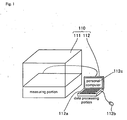
- Fig. 1 is a perspective view showing the whole structure of one embodiment of an analyzing apparatus and a data processing portion thereof.
- Fig. 2 is a perspective view showing the whole structure of the measuring portion of the analyzing apparatus illustrated in Fig. 1
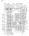
- Fig. 3 is a schematic plan view of Fig. 2 .
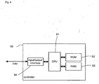
- Fig. 4 is a block diagram showing the structure of a controller illustrated in Fig. 2
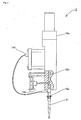
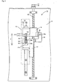
- Fig. 5 is a view showing the syringe portion of the measuring portion of the analyzing apparatus illustrated in Fig. 2
- Fig. 6 is a schematic view showing the syringe up-down portion of the measuring portion of the analyzing apparatus illustrated in Fig. 2
- Fig. 1 is a perspective view showing the whole structure of one embodiment of an analyzing apparatus and a data processing portion thereof.
- Fig. 2 is a perspective view showing the whole structure of the measuring portion of the analyzing apparatus illustrated in Fig. 1
- Fig. 3 is a schematic plan view of Fig. 2 .
- FIG. 7 is a schematic top view showing the syringe up-down portion in Fig. 6 .
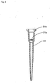
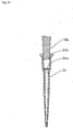
- Figs. 8 and 9 are views showing a pipette chip and a rack in the measuring portion of the analyzing apparatus illustrated in Fig. 2 .
- description will be given to a gene amplification detecting apparatus as an example of the analysing apparatus including a dispensing device.
- the gene amplification detecting apparatus is an analyzing apparatus for supporting the cancer metastasis diagnosis of an excised tissue in a cancer operation and serves to amplify a gene (mRNA) caused by a cancer present in the excised tissue by using a LAMP (Loop-mediated Isothermal Amplification) method and to measure the turbidity of a solution generated with the amplification, thereby carrying out a detection.
- LAMP Loop-mediated Isothermal Amplification
- an analyzing apparatus (a gene amplification detecting apparatus) 110 is constituted by a measuring portion 111 and a data processing portion 112 connected to the measuring portion 111 through a communication circuit.
- the data processing portion 112 is constituted by a personal computer including a keyboard 112a, a mouse 112b and a display portion 112c.
- the measuring portion 111 includes a dispensing mechanism portion 10, a sample vessel set portion 30, a reagent vessel set portion 40, a chip set portion 50, a chip discarding portion 60, a reaction detecting portion 70 formed by five reaction detecting blocks 70a, and a transfer portion 80 for transferring the dispensing mechanism portion 10 in an XY-axis direction.
- the measuring portion 111 includes a controller 90 and a power supply portion 100 for supplying a power to the whole apparatus including the controller 90 as shown in Fig. 2 .
- an emergency stop switch 101 is provided in the predetermined part of the front face of the measuring portion 111. As shown in Fig.
- the dispensing mechanism portion 10 includes an arm portion 11 to be moved in the X-axis and Y-axis directions (a plane direction) by means of the transfer portion 80, two syringe portions 12 which can be moved in a Z-axis direction (a perpendicular direction) independently with respect to the arm portion 11 respectively and are arranged in a transverse direction, and a syringe up-down portion 13 for moving the syringe portion 12 in the Z-axis direction.
- the syringe portion 12 further includes a nozzle 12a to/from which a pipette chip 51 to be described below is attached/removed at a tip, a pump 12b for carrying out a suction and a discharge through the nozzle 12a, a motor 12c for driving the pump 12b, an electrostatic capacity sensor 12d, and a pressure detecting sensor 12e as shown in Fig. 5 .
- the pump 12b moreover, it is possible to obtain the sucking and discharging functions of the syringe portion 12 by converting the rotation of the motor 12c into a piston motion.
- the electrostatic capacity sensor 12d is a sensor of an electrostatic capacity type and serves to detect the electrostatic capacities of the pipette chip 51 formed of a conductive resin and a liquid.
- the pressure detecting sensor 12e serves to detect a pressure in the suction and discharge to be carried out by the pump 12b. By the electrostatic capacity sensor 12d and the pressure detecting sensor 12e, whether the suction and discharge is surely carried out is detected.
- the syringe portion 13 is constituted by a base 14, a linear motion guide 15, a ball screw 16, a pulley 17 on a ball screw side, a pulley 18 on a motor side, a driving belt 19, a stepping motor 20, a syringe support portion 21, a lower compression coiled spring 22, an upper compression coiled spring 23, a stopper 24, a light transmission type sensor 25, and a shielding plate 26.
- the base 14 is attached to the front face of the arm portion 11 through a rail 15a and a slider 15b which constitute the linear motion guide 15.
- the base 14 is engaged with the ball screw 16.
- the ball screw 16 is provided to be extended in the Z-axis direction (vertical direction).
- the pulley 17 on the ball screw side is attached to the upper end of the ball screw 16 as shown in Figs. 6 and 7 .
- the stepping motor 20 is provided on the back face of the arm portion 11, and furthermore, the pulley 18 on the motor side is attached to the shaft of the stepping motor 20.
- the driving belt 19 is attached between the pulley 17 on the ball screw side and the pulley 18 on the motor side. Consequently, the base 14 is constituted to be moved in the Z-axis direction (the vertical direction) along the rail 15a with the rotation of the ball screw 16 by the driving operation of the stepping motor 20.
- the syringe support portion 21 is provided below the base 14 and supports the syringe portion 12 as shown in Fig. 6 .
- the syringe support portion 21 is fixed to a slider (not shown) attached slidably to the rail 15a in the same manner as the base 14. Consequently, the syringe support portion 21 is constituted movably in the Z-axis direction (the vertical direction) along the rail 15a.
- the syringe portion 12 is also moved integrally with the syringe support portion 21.
- a regulating portion 21a is provided to be protruded from the front face of the syringe support portion 21.
- a support shaft 21b extended upward is provided integrally with the upper face of the regulating portion 21a.
- the support shaft 21b includes a cylindrical spring support portion 21c having a predetermined diameter and a cylindrical slip stopping portion 21d provided on the upper side of the spring support portion 21c and having a larger diameter than the diameter of the spring support portion 21c.
- the base 14 is provided with a U-shaped nick portion 14a seen from above.
- the spring support portion 21c of the support shaft 21b is engaged with the nick portion 14a movably in the Z-axis direction and is constituted in such a manner that the support shaft 21b can be prevented from slipping from the nick portion 14a downward by the slip stopping portion 21d.
- the lower compression coiled spring 22, the upper compression coiled spring 23 and the stopper 24 are attached to the spring support portion 21c of the support shaft 21b, and the lower compression coiled spring 22 and the upper compression coiled spring 23 are provided in series through the stopper 24.
- a spring constant k1 of the lower compression coiled spring 22 is set to have a smaller value than the value of a spring constant k2 of the upper compression coiled spring 23.
- the upper end of the upper compression coiled spring 23 abuts on the lower face of the base 14, and furthermore, the lower end of the lower compression coiled spring 22 abuts on the upper face of the regulating portion 21a of the syringe support portion 21.
- the stopper 24 is provided with a concave portion 24a and a through hole 24b is formed on the bottom face of the concave portion 24a. Moreover, the stopper 24 is provided in such a manner that the opening portion side of the concave portion 24a is set to be a lower side, and the spring support portion 21c of the support shaft 21b is inserted in the through hole 24b. Furthermore, the stopper 24 is constituted to be relatively movable in the vertical direction with respect to the spring support portion 21c of the support shaft 21b. Furthermore, a part of the lower compression coiled spring 22 is accommodated in the concave portion 24a of the stopper 24.
- the lower compression coiled spring 22 is provided between the bottom face of the concave portion 24a of the stopper 24 and the upper face of the regulating portion 21a of the syringe support portion 21. Consequently, the lower end of the stopper 24 abuts on the upper face of the regulating portion 21a when the lower compression coiled spring 22 contracts, and the range of the contraction of the lower compression coiled spring 22 is thus regulated. More specifically, if the lower end of the stopper 24 abuts on the upper face of the regulating portion 21a when the lower compression coiled spring 22 contracts, the lower compression coiled spring 22 does not contract any more.
- the light transmission type sensor 25 is provided for detecting that the syringe portion 12 and the syringe support portion 21 are moved with respect to the base 14.
- the sensor 25 is attached to the side face of the base 14.
- the sensor 25 includes a light source portion 25a for irradiating a light and a light receiving portion 25b provided opposite to the light source portion 25a and serving to receive the light irradiated from the light source portion 25a as shown in Fig. 7 .
- the sensor 25 is constituted to output an ON signal when the light receiving portion 25b receives a light irradiated from the light source portion 25a and to output an OFF signal when the light receiving portion 25b does not receive the light irradiated from the light source portion 25a.
- the shielding plate 26 is provided to shield the light irradiated from the light source portion 25a of the sensor 25.
- the shielding plate 26 is attached to the syringe support portion 21 as shown in Fig. 6 .
- the shielding plate 26 has a rectangular nick portion 26a. A portion including the nick portion 26a of the shielding plate 26 is provided between the light source portion 25a and the light receiving portion 25b in the sensor 25 as shown in Fig. 7 .
- the nick portion 26a is provided in such a manner that the light irradiated from the light source portion 25a of the sensor 25 is incident on the light receiving portion 25b through the nick portion 26a when the syringe support portion 21 is moved in an upward direction so that the lower end of the stopper 24 abuts on the upper face of the regulating portion 21a of the syringe support portion 21.
- the controller 90 serves to detect positions in the Z-axis direction (the vertical direction) of the syringe support portion 21 and the syringe portion 12 based on the number of driving pulses (the amount of driving) of the stepping motor 20. Moreover, the controller 90 is constituted to detect whether the nozzle 12a of the syringe portion 12 is normally attached to the pipette chip 51 based on the output signal (ON/OFF signal) of the sensor 25 and the amount of driving of the stepping motor 20 (the number of driving pulses).
- a sample vessel set table 31 having five sample vessel set holes 31a and a holding portion 31b is removably fitted in a concave portion (not shown) of the sample vessel set portion 30.
- a sample vessel 32 accommodating a soluble extracted solution (sample) prepared by pretreating (homogenizing, filtering and diluting) an excised tissue is set to the five sample vessel set holes 31 a of the sample vessel set table 31.
- a reagent vessel set table 41 having two primer reagent vessel set holes 41a and one enzyme reagent vessel set hole 41b, and a holding portion 41c is removably fitted in a concave portion (not shown) of the reagent vessel set portion 40.
- the primer reagent vessel set hole 41 a of the reagent vessel set table 41 is provided at a predetermined interval in the Y-axis direction, and the enzyme reagent vessel set hole 41b is provided on only the left side of a front face.
- a primer reagent vessel 42a accommodating the primer reagent of ⁇ -actin and an enzyme reagent vessel 42b accommodating a common enzyme reagent to cytokeratin (CK19) and the ⁇ -actin are provided in the primer reagent vessel set hole 41a and the enzyme reagent vessel set hole 41b which are provided on the left side of the front face (see Fig. 3 ), respectively.
- a primer reagent vessel 42a accommodating a CK19 primer reagent is provided in the primer reagent vessel set hole 41a provided on the right side of the front face.
- two racks 52 are removably fitted in two concave portions (not shown) of the chip set portion 50.
- Each of the racks 52 has housing holes 52a capable of accommodating 36 pipette chips 51.
- two removal buttons 53 are provided on the chip set portion 50. By pressing the removal button 53, it is possible to bring a state in which the rack 52 can be removed.
- the pipette chip 51 is formed by a conductive resin material containing carbon, and furthermore, a filter 51a is attached to an inner part as shown in Fig. 8 .
- the filter 51 a has a function of preventing an erroneous flow into the pump 12b for a liquid.
- An electron beam irradiation is carried out in a packing state before shipment in such a manner that a degradative enzyme such as human saliva which might be stuck in a process for manufacturing the pipette chip 51 does not adversely influence the amplification of a gene.
- the rack 52 accommodating the pipette chip 51 is stored in a state in which a lower cover 54 and an upper cover 55 are attached as shown in Fig. 9 before setting to the chip set portion 50.
- a chip discarding portion 60 is provided with two chip discarding holes 60a for discarding the used pipette chip 51.
- a trench portion 60b having a smaller width than that of the chip discarding hole 60a is provided continuously with the chip discarding hole 60a.
- each reaction detecting block 70a of a reaction detecting portion 70 is constituted by a reacting portion 71, two turbidity detecting portions 72, and a cover closing mechanism portion 73 as shown in Fig. 2 .
- each reacting portion 71 is provided with two detecting cell set holes 71 a for setting a detecting cell 75.
- the turbidity detecting portion 72 is constituted by an LED light source portion 72a formed by a blue LED having a wavelength of 465 nm which is attached to a substrate 74a provided on one of the side faces of the reacting portion 71, and a photodiode light receiving portion 72b attached to the substrate 74b which is provided on the other side face of the reacting portion 71.
- Each reaction detecting block 70a is provided with two sets of turbidity detecting portions 72, each of which is constituted by an LED light source portion 72a and a photodiode light receiving portion 72b.
- reaction detecting blocks 70a are provided with ten sets of turbidity detecting portions 72 including the LED light source portions 72a and the photodiode light receiving portions 72b in total.
- the LED light source portion 72a and the photodiode light receiving portion 72b corresponding thereto are provided in such a manner that a light having a diameter of approximately 1 mm is irradiated from the LED light source portion 72a onto the lower part of the detecting cell 75 and a light can be thus received by the photodiode light receiving portion 72b.
- the LED light source portion 72a and the photodiode light receiving portion 72b have a function of detecting the presence of the detecting cell 75 depending on the intensity of a light received by the photodiode light receiving portion 72b and detecting (monitoring) the turbidity of a solution accommodated in the detecting cell 75 in real time.
- the transfer portion 80 includes a linear motion guide 81 and a ball screw 82 for transferring the dispensing mechanism portion 10 in the Y-axis direction, a stepping motor 83 for driving the ball screw 82, a linear motion guide 84 and a ball screw 85 for transferring the dispensing mechanism portion 10 in the X-axis direction, and a stepping motor 86 for driving the ball screw 85.
- a rail portion 81 a of the linear motion guide 81 and a support portion 82a of the ball screw 82 in the Y-axis direction are attached to a frame 87.
- the other support portion 82b of the ball screw 82 is attached to the frame 87 through the stepping motor 83.
- a slide portion 81b of the linear motion guide 81 in the Y-axis direction and a straight moving portion (not shown) of the ball screw 82 are attached to the arm portion 11 of the dispensing mechanism portion 10.
- a rail portion 84a of the linear motion guide 84 in the X-axis direction and a support portion 85a of the ball screw 85 are attached to a support table 88.
- a slide portion (not shown) of the linear motion guide 84 in the X-axis direction and the other support portion 85b of the ball screw 85 are attached to the frame 87.
- a stepping motor 86 is attached to the other support portion 85b of the ball screw 85.
- a transfer in the XY-axis direction of the dispensing mechanism portion 10 is carried out by rotating the ball screws 82 and 85 through the stepping motors 83 and 86, respectively.
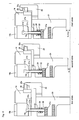
- Figs. 10 to 15 are views for explaining the operation of the above described analyzing apparatus.
- a "first state”, a “second state” and a “third state” in Fig. 11 correspond to the states of the base and the syringe support portion in Figs. 6 , 12 and 13 , respectively.
- Figs. 1 to 15 next, description will be given to the operation of the analyzing apparatus (gene amplification detecting apparatus) according to the present embodiment.
- a gene (mRNA) caused by a cancer present in an excised tissue in a cancer operation is amplified by using a LAMP method and the turbidity of a solution generated with the amplification is measured to carry out a detection.
- the sample vessel 32 accommodating a soluble extracted solution (sample) prepared by pretreating (homogenizing, filtering and diluting) an excised tissue is set to the sample vessel set hole 31 a of the sample vessel set table 31.
- the primer reagent vessel 42a accommodating the primer reagent of the ⁇ -actin
- the enzyme reagent vessel 42b accommodating a common enzyme reagent to the cytokeratin (CK19) and the ⁇ -actin are set to the primer reagent vessel set hole 41a and the enzyme reagent vessel set hole 41b which are provided on the left side of the front face, respectively.
- the primer reagent vessel 42a accommodating the primer reagent of the CK19 is set to the primer reagent vessel set hole 41a provided on the right side of the front face.
- each of the two racks 52 which accommodates 36 disposable pipette chips 51 is fitted in the concave portion (not shown) of the chip set portion 50.
- the initial position (origin position) of the arm portion 11 of the dispensing mechanism portion 10 is shifted from the upper part of the chip set portion 50 as shown in Figs. 2 and 3 . Therefore, the two racks 52 can easily be fitted in the concave portion (not shown) of the chip set portion 50.
- two cell portions 76a of the detecting cell 75 are set to two detecting cell set holes 71 a of the reacting portion 71 of each reaction detecting block 70a.
- the operation of the measuring portion 111 is started by means of the keyboard 112a or the mouse 112b.
- the arm portion 11 of the dispensing mechanism portion 10 is first moved from the initial position to the chip set portion 50 by means of the transfer portion 80. Then, the stepping motor 20 of the syringe up-down portion 13 (see Fig. 7 ) is driven so that the ball screw 16 is rotated. Consequently, the base 14 of the syringe up-down portion 13 is moved in a downward direction. In the chip set portion 50 (see Fig. 2 ), consequently, the two syringe portions 12 of the dispensing mechanism portion 10 and the syringe support portion 21 are moved in the downward direction.
- the nozzle 12a of the syringe portion 12 in the case in which the tip of the nozzle 12a of the syringe portion 12 is normally inserted in the opening portion of the upper part of the pipette chip 51 as shown in Fig. 10 , the nozzle 12a abuts on the internal wall surface of the pipette chip 51 when the tip of the nozzle 12a reaches a downward position from the upper face of a flange portion 51b of the pipette chip 51 by approximately 2 mm to 3 mm. Consequently, the nozzle 12a receives an upward force. Therefore, the syringe portion 12 and the syringe support portion 21 are moved in an upward direction by a distance x1 (see Fig.
- the syringe portion 12 and the syringe support portion 21 are changed from a first state (see Figs. 6 and 11 ) in which the nozzle 12a does not abut on the pipette chip 51 to a second state (see Figs. 11 and 12 ).
- the lower compression coiled spring 22 contracts by the distance x1 so that the lower end of the stopper 24 abuts on the upper face of the regulating portion 21a of the syringe support portion 21. Consequently, the lower compression coiled spring 22 contracts by the distance x1 or less.
- the controller 90 decides whether or not the output of the sensor 25 is set into the ON state when the nozzle 12a of the syringe portion 12 reaches a preset normal downward position based on the number of the driving pulses of the stepping motor 20 and the output of the sensor 25. If the controller 90 decides that the sensor 25 is set into the ON state when the nozzle 12a of the syringe portion 12 reaches the preset normal downward position (see Fig. 10 ), it is decided that the nozzle 12a of the syringe portion 12 is brought down to a position in which it is normally pressed into the pipette chip 51.
- the controller 90 decides that the sensor 25 is set into the ON state before the nozzle 12a of the syringe portion 12 reaches the preset normal downward position based on the number of the driving pulses of the stepping motor 20 and the output of the sensor 25, and furthermore, decides that the nozzle 12a of the syringe portion 12 comes in contact with the flange portion 51b of the pipette chip 51.
- the spring constant k1 of the lower compression coiled spring 22 is much smaller than the spring constant k2 of the upper compression coiled spring 23.
- the controller 90 stops the movement of the base 14 in the downward direction and then causes the display portion 112c of the data processing portion 112 to display an error message. Thereafter an error return processing is carried out by a user.
- the spring constant k2 of the upper compression coiled spring 23 is greater than the spring constant of the lower compression coiled spring. Therefore, the elastic force F2 generated by the lower compression coiled spring and the upper compression coiled spring becomes comparatively great.
- the nozzle 12a of the syringe portion 12 is pressed into the opening portion of the upper part of the pipette chip 51 by the elastic force F2. As shown in Fig.
- the nozzle 12a is pressed into a position in which a distance from the tip of the nozzle 12a to the filter 51 a of the pipette chip 51 is approximately 1 mm.
- a portion between the light source portion 25a (see Fig. 7 ) and the light receiving portion 25b (see Fig. 7 ) in the sensor 25 is blocked by a lower part from the nick portion 26a of the shielding plate 26. Therefore, the sensor 25 is brought into the OFF state.
- the pipette chip 51 is attached to the tip of the nozzle 12a in each of the two syringe portions 12 as shown in Fig. 5 .
- the arm portion 11 of the dispensing mechanism portion 10 is moved in the X-axis direction toward the upper parts of the two primer reagent vessels 42a accommodating the primer reagents of the CK19 and the ⁇ -actin which are set onto the reagent vessel set table 41 by means of the transfer portion 80.
- the stepping motor 20 is driven so that the two syringe portions 12 are moved in the downward direction. Consequently, the tips of the two pipette chips 51 attached to the nozzles 12a of the two syringe portions 12 are inserted into the liquid levels of the primer reagents of the CK19 and the ⁇ -actin in the two primer reagent vessels 42a, respectively. Thereafter, the primer reagents of the CK19 and the ⁇ -actin in the two primer reagent vessels 42a are sucked by the pump 12b of the syringe portion 12.
- the controller 90 detects whether or not the suction is reliably carried out.
- the stepping motor 20 is driven so that the two syringe portions 12 are moved upward and the arm portion 11 of the dispensing mechanism portion 10 is then moved toward the upper part of the reaction detecting block 70a positioned on an innermost side (the inner side of the front face of the apparatus) by means of the transfer portion 80.
- the two syringe portions 12 positioned in the upper part of the reaction detecting block 70a on the innermost side are moved in the downward direction by the operation of the stepping motor 20. Consequently, the two pipette chips 51 attached to the nozzles 12a of the two syringe portions 12 are inserted into the two cell portions 76a of the detecting cell 75, respectively.
- the two primer reagents of the CK19 and the ⁇ -actin are discharged to the two cell portions 76a, respectively. Also in case of the discharge (exhaust), in the same manner as in the case of the suction, it is detected that the tip of the pipette chip 41 formed by the conductive resin comes in contact with the liquid level by means of the electrostatic capacity sensor 12d (see Fig. 5 ) (liquid level detection), and furthermore, a pressure in the discharge of the pump 12b is detected by means of the pressure detecting sensor 12e.
- the signals output from the electrostatic capacity sensor 12d and the pressure detecting sensor 12e are given to the controller 90 so that the controller 90 detects whether or not the discharge is reliably carried out. Also in the suction and discharge of the following enzyme reagent and sample, a liquid level is detected by means of the electrostatic capacity sensor 12d and a pressure in a suction and discharge is detected by means of the pressure detecting sensor 12e in the same manner as described above.
- the two syringe portions 12 are moved upward by the operation of the stepping motor 20. Then, the arm portion 11 of the dispensing mechanism portion 10 is moved in the X-axis direction toward the upper part of the chip discarding portion 60 by means of the transfer portion 80. Thereafter, the pipette chip 51 is discarded in the chip discarding portion 60. More specifically, the two syringe portions 12 are moved in the downward direction by the operation of the stepping motor 20 so that the pipette chip 51 is inserted into the two chip discarding holes 60a (see Fig. 3 ) of the chip discarding portion 60.
- the arm portion 11 of the dispensing mechanism portion 10 is moved in the Y-axis direction by means of the transfer portion 80. Consequently, the pipette chip 51 is moved to the lower part of the trench portion 60b. Then, the stepping motor 20 is driven so that the two syringe portions 12 are moved in the upward direction. Therefore, the collar portion of the upper face of the pipette chip 51 abuts on lower faces at both sides of the trench portion 60b and receives a force in the downward direction from the lower faces thereof. Consequently, the pipette chip 51 is automatically separated from the nozzles 12a of the two syringe portions 12. Thus, the pipette chip 51 is discarded into the chip discarding portion 60. While the pipette chip 51 discarded into the chip discarding portion 60 is exactly discarded in the present embodiment, it is not restricted thereto but the pipette chip 51 collected in the chip discarding portion 60 may be washed and recycled.
- the arm portion 11 of the dispensing mechanism portion 10 is moved to the chip set portion 50 by means of the transfer portion 80 again.
- the syringe portion 12 is moved to the chip set portion 50, two new pipette chips 51 are automatically attached to the tips of the nozzles 12a of the two syringe portions 12 by the same operation as described above in the chip set portion 50.
- the arm portion 11 of the dispensing mechanism portion 10 is moved in the X-axis direction by means of the transfer portion 80 toward the upper part of the enzyme reagent vessel 42b accommodating a common enzyme reagent to the CK19 and the ⁇ -actin which is set to the reagent vessel set table 41, and the enzyme reagent in the enzyme reagent vessel 42b is then sucked.
- the stepping motor 20 and the pump 12b are driven so that one of the syringe portions 12 positioned in the upper part of the enzyme reagent vessel 42b is moved in the downward direction to suck the enzyme reagent and the same syringe portion 12 is then moved in the upward direction.
- the arm portion 11 of the dispensing mechanism portion 10 is moved in the Y-axis direction by means of the transfer portion 80 in such a manner that the other syringe portion 12 is positioned above the same enzyme reagent vessel 42b.
- the stepping motor 20 and the pump 12b are driven so that the other syringe portion 12 is moved in the downward direction to suck the enzyme reagent from the same enzyme reagent vessel 42b, and then, the other syringe portion 12 is moved in the upward direction.
- the arm portion 11 of the dispensing mechanism portion 10 is moved toward the upper part of the reaction detecting block 70a on an innermost side by means of the transfer portion 80, the common enzyme reagent to the CK19 and the ⁇ -actin is discharged to the two cell portions 76a of the detecting cell 75.
- the arm portion 11 of the dispensing mechanism portion 10 is moved toward the upper part of the chip discarding portion 60 by means of the transfer portion 80 and the pipette chip 51 is then discarded.
- the arm portion 11 of the dispensing mechanism portion 10 is moved to the chip set portion 50 by means of the transfer portion 80 again. Then, two new pipette chips 51 are automatically attached to the tips of the nozzles 12a of the two syringe portions 12 by the same operation as described above. Thereafter, the arm portion 11 of the dispensing mechanism portion 10 is moved in the X-axis direction toward the upper part of the sample vessel 32 accommodating a sample which is set to the sample vessel set table 31 by means of the transfer portion 80. By the same operation as the operation for sucking the enzyme reagent, thereafter, the sample in the sample vessel 32 is sucked.
- the arm portion 11 of the dispensing mechanism portion 10 is moved toward the upper part of the reaction detecting block 70a on the innermost side by means of the transfer portion 80. Then, the two syringe portions 12 are moved in the downward direction so that the same sample is discharged to the two cell portions 76a of the detecting cell 75.
- the sucking and discharging operations are repeated at plural times by using the pumps 12b of the two syringe portions 12 so that the primer reagent and the enzyme reagent of the CK19 and the ⁇ -actin accommodated in the two cell portions 76a and the sample are stirred.
- the temperature of a liquid in the detecting cell 75 is held at approximately 20°C. Then, the arm portion 11 of the dispensing mechanism portion 10 is moved toward the upper part of the chip discarding portion 60 by means of the transfer portion 80 and the pipette chip 51 is thereafter discarded.
- the cover closing operation of the cover portion 77a of the detecting cell 75 is carried out.
- the temperature of the liquid in the detecting cell 75 is raised from approximately 20°C to approximately 65°C, thereby amplifying a target gene (mRNA) by a LAMP (gene amplification) reaction.
- mRNA target gene
- LAMP gene amplification
- a liquid turbidity in the detecting cell 75 in the amplifying reaction is detected (monitored) in real time by using the LED light source portion 72a and the photodiode light receiving portion 72b shown in Fig. 3 , thereby detecting the liquid turbidity.
- the lower compression coiled spring 22 and the upper compression coiled spring 23 for suppressing the movement of the syringe portion 12 and the syringe support portion 21 with respect to the base 14 are provided and the lower compression coiled spring 22 has the smaller spring constant k1 than the spring constant k2 of the upper compression coiled spring 23 as described above.
- the analyzing apparatus including the dispensing device according to the present invention is applied to the gene amplification detecting apparatus for amplifying a target gene by a LAMP method in the above embodiment.
- the present invention is not restricted thereto, and the same analyzing apparatus may be applied to a gene amplification detecting apparatus for amplifying a target gene by a polymerase chain reaction method (PCR method) or a ligase chain reaction method (LCR method).
- PCR method polymerase chain reaction method
- LCR method a ligase chain reaction method
- the analyzing apparatus including the dispensing device according to the present invention may be applied to an analyzing apparatus other than the gene amplification detecting apparatus.
- the present invention is not restricted thereto but an elastic member other than the compression coiled spring, for example, rubber may be used. Furthermore, it is also possible to use means for generating an energizing force with respect to the movement of the syringe portion 12 other than the elastic member, for example, an energizing force generating mechanism for generating the energizing force by an actuator such as a motor or a cylinder.
- a holding member for holding the support shaft 21b to the base 14 and to cause a force in a downward direction to act on the syringe support portion 21 when the syringe support portion 21 is moved upward with respect to the base 14 by the holding force of the holding member.
- the lower compression coiled spring 22 having a small elastic constant is provided on the underside of the upper compression coiled spring 23 having a great elastic constant in the above embodiment, moreover, it is not restricted thereto but the compression coiled spring having a great elastic constant may be provided on the underside of the compression coiled spring having a small elastic constant.
- the present invention is not restricted thereto but the lower compression coiled spring 22 and the upper compression coiled spring 23 may be provided along separate axes, respectively.
- the diameters and lengths of the two compression coiled springs may be different from each other and one of the compression coiled springs may be provided to surround the outside of the other compression coiled spring. In this case, after the longer compression coiled spring contracts earlier and the lengths of both of the compression coiled springs become equal to each other, both of the compression coiled springs contract at the same time.
- an energizing force acting on the syringe portion 12 is small while only the longer compression coiled spring contracts. Therefore, the contact of the syringe portion 12 with the pipette chip 51 can be detected with high precision for the time. Moreover, the energizing force acting on the syringe portion 12 is great while both of the compression coiled springs contract. Therefore, it is possible to sufficiently relieve a shock caused by the contact of the nozzle 12a with the pipette chip 51 for the time.
- the optical sensor is used as the detector in the above embodiment, furthermore, the apparatus is not restricted thereto but an electrical sensor such as a microswitch may be used as the detector.
- the apparatus is not restricted thereto but the apparatus can also be applied when the chip attaching member having the dispensing chip attached thereto is detected to come in contact with another predetermined object in a movement in a downward direction.
Landscapes
- Physics & Mathematics (AREA)
- Health & Medical Sciences (AREA)
- Life Sciences & Earth Sciences (AREA)
- Chemical & Material Sciences (AREA)
- Analytical Chemistry (AREA)
- Biochemistry (AREA)
- General Health & Medical Sciences (AREA)
- General Physics & Mathematics (AREA)
- Immunology (AREA)
- Pathology (AREA)
- Automatic Analysis And Handling Materials Therefor (AREA)
- Sampling And Sample Adjustment (AREA)
Abstract
Description
- The present invention relates to a dispensing device and an analyzing apparatus comprising the same. Such a dispensing device may include a chip attaching member to which a dispensing chip is attached.
- Conventionally, there has been known a dispensing device including a chip attaching member to which a dispensing chip is attached (for example, see Japanese Laid-Open Patent Publication No.
2003-344427 - The Japanese Laid-Open Patent Publication No.
2003-344427 JP 10-038 896 A - In the dispensing device disclosed in the Japanese Laid-Open Patent Publication No.
2003-344427 - According to the present invention, there is provided a dispensing device comprising: a base which can be moved in a first direction; a chip attaching member, which is provided movably within a predetermined moving range in a second direction opposite to the first direction with respect to the base, and to which a dispensing chip can be removably attached by a movement of the base in the first direction; effort applying means for applying an effort to the chip attaching member in the first direction and changing the magnitude of the effort when the chip attaching member is moved a first distance (X1) in the second direction with respect to the base; a detector for detecting that the chip attaching member has been moved said first distance (X1) in the second direction with respect to the base, and for detecting that the chip attaching member has been moved a second distance (X1+X2) greater than the first distance (X1) in the second direction with respect to the base; a driving source for moving the base; and a controller for monitoring whether or not the dispensing chip is normally attached to the chip attaching member, wherein: the controller is configured to monitor the attachment of the dispensing chip to the chip attaching member based on an amount of driving of the driving source and an output of the detector when the chip attaching member has been moved said first distance (X1) and an output of the detector when the chip attaching member has been moved said second distance (X1+X2) in said direction with respect to the base
- An analyzing apparatus comprising a dispensing device according to the invention for dispensing a sample; and a transfer device for transferring the dispensing device is also provided.
- For a better understanding of the present invention and to show how the same may be carried into effect, reference will now be made, by way of example, to the accompanying drawings, in which:
-
Fig. 1 is a perspective view showing the whole structures of an analyzing apparatus (a gene amplification detecting apparatus) and a data processing portion thereof according to an embodiment of the analyzing apparatus; -
Fig. 2 is a perspective view showing the whole structure of the measuring portion of the analyzing apparatus according to the embodiment illustrated inFig. 1 ; -
Fig. 3 is a schematic plan view showing the measuring portion of the analyzing apparatus according to the embodiment illustrated inFig. 2 ; -
Fig. 4 is a block diagram showing the structure of a controller illustrated inFig. 2 ; -
Fig. 5 is a schematic view showing the structure of a syringe portion in the measuring portion of the analyzing apparatus according to the embodiment illustrated inFig. 2 ; -
Fig. 6 is a schematic view showing the structure of the syringe up-down portion of the analyzing apparatus according to the embodiment illustrated inFig. 2 ; -
Fig. 7 is a schematic top view showing the syringe up-down portion according to the embodiment illustrated inFig. 5 ; -
Fig. 8 is a sectional view showing the structure of a pipette chip to be used in the analyzing apparatus according to the embodiment illustrated inFig. 2 ; -
Fig. 9 is a perspective view showing the storage state of a rack for accommodating the pipette chip to be used in the analyzing apparatus according to the embodiment illustrated inFig. 2 ; -
Fig. 10 is a sectional view showing a state in which the nozzle of the syringe portion of the analyzing apparatus according to the embodiment illustrated inFig. 2 is normally inserted in the pipette chip; -
Fig. 11 is a view for explaining the operation of the analyzing apparatus of the illustrated embodiment; -
Fig. 12 is a view for explaining the operation of the analyzing apparatus of the illustrated embodiment; -
Fig. 13 is a view for explaining the operation of the analyzing apparatus of the illustrated embodiment; -
Fig. 14 is a sectional view showing a state in which the nozzle of the syringe portion of the analyzing apparatus according to the embodiment illustrated inFig. 2 is normally pressed into the pipette chip; and -
Fig. 15 is a sectional view showing a state in which the nozzle of the syringe portion of the analyzing apparatus according to the embodiment illustrated inFig. 2 is provided in contact with the pipette chip. - A dispensing device is described, comprising a base; a chip attaching member which is provided movably with respect to the base and to which a dispensing chip is attached removably; a first elastic member for suppressing a movement of the chip attaching member with respect to the base; a second elastic member serving to suppress the movement of the chip attaching member with respect to the base and having a greater elastic constant than an elastic constant of the first elastic member; and a detector for detecting that the chip attaching member is moved with respect to the base.
- A dispensing device is described comprising a base which can be moved in a first direction; a chip attaching member which is provided movably in a second direction to be an opposite direction to the first direction with respect to the base and to which a dispensing chip is attached by a movement of the base in the first direction; first energizing means for giving a first energizing force directed at the first direction to the chip attaching member; second energizing means for giving a second energizing force directed at the first direction to the chip attaching member, the second energizing force being greater than the first energizing force; and a detector for detecting that the chip attaching member is moved in the second direction with respect to the base.
- An analyzing apparatus is described comprising a base; a chip attaching member which is provided movably with respect to the base and to which a dispensing chip is attached removably; a first elastic member for suppressing a movement of the chip attaching member with respect to the base; a second elastic member serving to suppress the movement of the chip attaching member with respect to the base and having a greater elastic constant than an elastic constant of the first elastic member; and a detector for detecting that the chip attaching member is moved with respect to the base.
- An embodiment of an analyzing apparatus will be described below with reference to the drawings.
-
Fig. 1 is a perspective view showing the whole structure of one embodiment of an analyzing apparatus and a data processing portion thereof.Fig. 2 is a perspective view showing the whole structure of the measuring portion of the analyzing apparatus illustrated inFig. 1 , andFig. 3 is a schematic plan view ofFig. 2 .Fig. 4 is a block diagram showing the structure of a controller illustrated inFig. 2 ,Fig. 5 is a view showing the syringe portion of the measuring portion of the analyzing apparatus illustrated inFig. 2 ,Fig. 6 is a schematic view showing the syringe up-down portion of the measuring portion of the analyzing apparatus illustrated inFig. 2 , andFig. 7 is a schematic top view showing the syringe up-down portion inFig. 6 .Figs. 8 and9 are views showing a pipette chip and a rack in the measuring portion of the analyzing apparatus illustrated inFig. 2 . In the present embodiment, description will be given to a gene amplification detecting apparatus as an example of the analysing apparatus including a dispensing device. The gene amplification detecting apparatus according to the present embodiment is an analyzing apparatus for supporting the cancer metastasis diagnosis of an excised tissue in a cancer operation and serves to amplify a gene (mRNA) caused by a cancer present in the excised tissue by using a LAMP (Loop-mediated Isothermal Amplification) method and to measure the turbidity of a solution generated with the amplification, thereby carrying out a detection. The details of the LAMP method have been disclosed inUS Patent No. 6410278 . - First of all, referring to
Fig. 1 , description will be given to the whole structure of the analyzing apparatus (the gene amplification detecting apparatus) and the data processing portion thereof according to the present embodiment. As shown inFig. 1 , an analyzing apparatus (a gene amplification detecting apparatus) 110 according to the present embodiment is constituted by ameasuring portion 111 and adata processing portion 112 connected to themeasuring portion 111 through a communication circuit. Thedata processing portion 112 is constituted by a personal computer including akeyboard 112a, amouse 112b and adisplay portion 112c. - As shown in
Figs. 2 and3 , themeasuring portion 111 includes adispensing mechanism portion 10, a sample vessel setportion 30, a reagent vessel setportion 40, a chip setportion 50, achip discarding portion 60, areaction detecting portion 70 formed by fivereaction detecting blocks 70a, and atransfer portion 80 for transferring thedispensing mechanism portion 10 in an XY-axis direction. Moreover, themeasuring portion 111 includes acontroller 90 and a power supply portion 100 for supplying a power to the whole apparatus including thecontroller 90 as shown inFig. 2 . Moreover, anemergency stop switch 101 is provided in the predetermined part of the front face of themeasuring portion 111. As shown inFig. 4 , thecontroller 90 includes aCPU 91, aROM 92, aRAM 93 and an input/output interface 94. TheROM 92 stores an operating system, a control program for controlling the operation of the apparatus, and necessary data for executing the control program. TheCPU 91 can execute the control program with loading to theRAM 93 or directly from theROM 92. Thus, data on the result of the processing of theCPU 91 are transmitted to each portion of the apparatus or the outside of the apparatus through the input/output interface 94, and the necessary data for the processing of theCPU 91 are received from each portion of the apparatus or the outside of the apparatus through the input/output interface 94. - Moreover, the
dispensing mechanism portion 10 includes anarm portion 11 to be moved in the X-axis and Y-axis directions (a plane direction) by means of thetransfer portion 80, twosyringe portions 12 which can be moved in a Z-axis direction (a perpendicular direction) independently with respect to thearm portion 11 respectively and are arranged in a transverse direction, and a syringe up-downportion 13 for moving thesyringe portion 12 in the Z-axis direction. Furthermore, thesyringe portion 12 further includes anozzle 12a to/from which apipette chip 51 to be described below is attached/removed at a tip, apump 12b for carrying out a suction and a discharge through thenozzle 12a, amotor 12c for driving thepump 12b, anelectrostatic capacity sensor 12d, and apressure detecting sensor 12e as shown inFig. 5 . In thepump 12b, moreover, it is possible to obtain the sucking and discharging functions of thesyringe portion 12 by converting the rotation of themotor 12c into a piston motion. Theelectrostatic capacity sensor 12d is a sensor of an electrostatic capacity type and serves to detect the electrostatic capacities of thepipette chip 51 formed of a conductive resin and a liquid. In addition, thepressure detecting sensor 12e serves to detect a pressure in the suction and discharge to be carried out by thepump 12b. By theelectrostatic capacity sensor 12d and thepressure detecting sensor 12e, whether the suction and discharge is surely carried out is detected. - As shown in
Figs. 6 and7 , furthermore, thesyringe portion 13 is constituted by abase 14, alinear motion guide 15, aball screw 16, apulley 17 on a ball screw side, apulley 18 on a motor side, adriving belt 19, astepping motor 20, asyringe support portion 21, a lower compression coiledspring 22, an upper compression coiledspring 23, astopper 24, a lighttransmission type sensor 25, and ashielding plate 26. - As shown in
Fig. 7 , moreover, thebase 14 is attached to the front face of thearm portion 11 through arail 15a and aslider 15b which constitute thelinear motion guide 15. As shown inFig. 6 , moreover, thebase 14 is engaged with theball screw 16. Theball screw 16 is provided to be extended in the Z-axis direction (vertical direction). Furthermore, thepulley 17 on the ball screw side is attached to the upper end of theball screw 16 as shown inFigs. 6 and7 . In addition, thestepping motor 20 is provided on the back face of thearm portion 11, and furthermore, thepulley 18 on the motor side is attached to the shaft of thestepping motor 20. Thedriving belt 19 is attached between thepulley 17 on the ball screw side and thepulley 18 on the motor side. Consequently, thebase 14 is constituted to be moved in the Z-axis direction (the vertical direction) along therail 15a with the rotation of theball screw 16 by the driving operation of thestepping motor 20. - Moreover, the
syringe support portion 21 is provided below thebase 14 and supports thesyringe portion 12 as shown inFig. 6 . Thesyringe support portion 21 is fixed to a slider (not shown) attached slidably to therail 15a in the same manner as thebase 14. Consequently, thesyringe support portion 21 is constituted movably in the Z-axis direction (the vertical direction) along therail 15a. In the case in which thesyringe support portion 21 is moved, thesyringe portion 12 is also moved integrally with thesyringe support portion 21. Furthermore, a regulatingportion 21a is provided to be protruded from the front face of thesyringe support portion 21. Asupport shaft 21b extended upward is provided integrally with the upper face of the regulatingportion 21a. Thesupport shaft 21b includes a cylindricalspring support portion 21c having a predetermined diameter and a cylindricalslip stopping portion 21d provided on the upper side of thespring support portion 21c and having a larger diameter than the diameter of thespring support portion 21c. As shown inFig. 7 , moreover, thebase 14 is provided with aU-shaped nick portion 14a seen from above. Thespring support portion 21c of thesupport shaft 21b is engaged with thenick portion 14a movably in the Z-axis direction and is constituted in such a manner that thesupport shaft 21b can be prevented from slipping from thenick portion 14a downward by theslip stopping portion 21d. - In the present embodiment, as shown in
Fig. 6 , the lower compression coiledspring 22, the upper compression coiledspring 23 and thestopper 24 are attached to thespring support portion 21c of thesupport shaft 21b, and the lower compression coiledspring 22 and the upper compression coiledspring 23 are provided in series through thestopper 24. Moreover, a spring constant k1 of the lower compression coiledspring 22 is set to have a smaller value than the value of a spring constant k2 of the upper compression coiledspring 23. Furthermore, the upper end of the upper compression coiledspring 23 abuts on the lower face of thebase 14, and furthermore, the lower end of the lower compression coiledspring 22 abuts on the upper face of the regulatingportion 21a of thesyringe support portion 21. By the lower compression coiledspring 22 and the upper compression coiledspring 23, thesyringe support portion 21 is energized in a separating direction from the base 14 (a downward direction). Consequently, thesyringe support portion 21 is prevented from being moved in an approaching direction (an upward direction) with respect to thebase 14. - In addition, the
stopper 24 is provided with aconcave portion 24a and a throughhole 24b is formed on the bottom face of theconcave portion 24a. Moreover, thestopper 24 is provided in such a manner that the opening portion side of theconcave portion 24a is set to be a lower side, and thespring support portion 21c of thesupport shaft 21b is inserted in the throughhole 24b. Furthermore, thestopper 24 is constituted to be relatively movable in the vertical direction with respect to thespring support portion 21c of thesupport shaft 21b. Furthermore, a part of the lower compression coiledspring 22 is accommodated in theconcave portion 24a of thestopper 24. In addition, the lower compression coiledspring 22 is provided between the bottom face of theconcave portion 24a of thestopper 24 and the upper face of the regulatingportion 21a of thesyringe support portion 21. Consequently, the lower end of thestopper 24 abuts on the upper face of the regulatingportion 21a when the lower compression coiledspring 22 contracts, and the range of the contraction of the lower compression coiledspring 22 is thus regulated. More specifically, if the lower end of thestopper 24 abuts on the upper face of the regulatingportion 21a when the lower compression coiledspring 22 contracts, the lower compression coiledspring 22 does not contract any more. - Moreover, the light
transmission type sensor 25 is provided for detecting that thesyringe portion 12 and thesyringe support portion 21 are moved with respect to thebase 14. Thesensor 25 is attached to the side face of thebase 14. Furthermore, thesensor 25 includes alight source portion 25a for irradiating a light and alight receiving portion 25b provided opposite to thelight source portion 25a and serving to receive the light irradiated from thelight source portion 25a as shown inFig. 7 . In addition, thesensor 25 is constituted to output an ON signal when thelight receiving portion 25b receives a light irradiated from thelight source portion 25a and to output an OFF signal when thelight receiving portion 25b does not receive the light irradiated from thelight source portion 25a. Moreover, the shieldingplate 26 is provided to shield the light irradiated from thelight source portion 25a of thesensor 25. The shieldingplate 26 is attached to thesyringe support portion 21 as shown inFig. 6 . Furthermore, the shieldingplate 26 has arectangular nick portion 26a. A portion including thenick portion 26a of the shieldingplate 26 is provided between thelight source portion 25a and thelight receiving portion 25b in thesensor 25 as shown inFig. 7 . In addition, thenick portion 26a is provided in such a manner that the light irradiated from thelight source portion 25a of thesensor 25 is incident on thelight receiving portion 25b through thenick portion 26a when thesyringe support portion 21 is moved in an upward direction so that the lower end of thestopper 24 abuts on the upper face of the regulatingportion 21a of thesyringe support portion 21. - Furthermore, the
controller 90 serves to detect positions in the Z-axis direction (the vertical direction) of thesyringe support portion 21 and thesyringe portion 12 based on the number of driving pulses (the amount of driving) of the steppingmotor 20. Moreover, thecontroller 90 is constituted to detect whether thenozzle 12a of thesyringe portion 12 is normally attached to thepipette chip 51 based on the output signal (ON/OFF signal) of thesensor 25 and the amount of driving of the stepping motor 20 (the number of driving pulses). - As shown in
Figs. 2 and3 , moreover, a sample vessel set table 31 having five sample vessel setholes 31a and a holdingportion 31b is removably fitted in a concave portion (not shown) of the sample vessel setportion 30. Asample vessel 32 accommodating a soluble extracted solution (sample) prepared by pretreating (homogenizing, filtering and diluting) an excised tissue is set to the five sample vessel set holes 31 a of the sample vessel set table 31. - Furthermore, a reagent vessel set table 41 having two primer reagent vessel set
holes 41a and one enzyme reagent vessel sethole 41b, and a holdingportion 41c is removably fitted in a concave portion (not shown) of the reagent vessel setportion 40. The primer reagent vessel sethole 41 a of the reagent vessel set table 41 is provided at a predetermined interval in the Y-axis direction, and the enzyme reagent vessel sethole 41b is provided on only the left side of a front face. Aprimer reagent vessel 42a accommodating the primer reagent of β-actin and anenzyme reagent vessel 42b accommodating a common enzyme reagent to cytokeratin (CK19) and theβ-actin are provided in the primer reagent vessel sethole 41a and the enzyme reagent vessel sethole 41b which are provided on the left side of the front face (seeFig. 3 ), respectively. In addition, aprimer reagent vessel 42a accommodating a CK19 primer reagent is provided in the primer reagent vessel sethole 41a provided on the right side of the front face. - Moreover, two
racks 52 are removably fitted in two concave portions (not shown) of the chip setportion 50. Each of theracks 52 hashousing holes 52a capable of accommodating 36 pipette chips 51. In addition, tworemoval buttons 53 are provided on the chip setportion 50. By pressing theremoval button 53, it is possible to bring a state in which therack 52 can be removed. Thepipette chip 51 is formed by a conductive resin material containing carbon, and furthermore, afilter 51a is attached to an inner part as shown inFig. 8 . Thefilter 51 a has a function of preventing an erroneous flow into thepump 12b for a liquid. An electron beam irradiation is carried out in a packing state before shipment in such a manner that a degradative enzyme such as human saliva which might be stuck in a process for manufacturing thepipette chip 51 does not adversely influence the amplification of a gene. Moreover, therack 52 accommodating thepipette chip 51 is stored in a state in which alower cover 54 and anupper cover 55 are attached as shown inFig. 9 before setting to the chip setportion 50. - As shown in
Fig. 3 , furthermore, achip discarding portion 60 is provided with twochip discarding holes 60a for discarding the usedpipette chip 51. In addition, atrench portion 60b having a smaller width than that of thechip discarding hole 60a is provided continuously with thechip discarding hole 60a. - Moreover, each
reaction detecting block 70a of areaction detecting portion 70 is constituted by a reactingportion 71, twoturbidity detecting portions 72, and a coverclosing mechanism portion 73 as shown inFig. 2 . As shown inFig. 3 , each reactingportion 71 is provided with two detecting cell set holes 71 a for setting a detectingcell 75. - As shown in
Fig. 3 , moreover, theturbidity detecting portion 72 is constituted by an LEDlight source portion 72a formed by a blue LED having a wavelength of 465 nm which is attached to asubstrate 74a provided on one of the side faces of the reactingportion 71, and a photodiodelight receiving portion 72b attached to thesubstrate 74b which is provided on the other side face of the reactingportion 71. Eachreaction detecting block 70a is provided with two sets ofturbidity detecting portions 72, each of which is constituted by an LEDlight source portion 72a and a photodiodelight receiving portion 72b. Accordingly, fivereaction detecting blocks 70a are provided with ten sets ofturbidity detecting portions 72 including the LEDlight source portions 72a and the photodiodelight receiving portions 72b in total. The LEDlight source portion 72a and the photodiodelight receiving portion 72b corresponding thereto are provided in such a manner that a light having a diameter of approximately 1 mm is irradiated from the LEDlight source portion 72a onto the lower part of the detectingcell 75 and a light can be thus received by the photodiodelight receiving portion 72b. The LEDlight source portion 72a and the photodiodelight receiving portion 72b have a function of detecting the presence of the detectingcell 75 depending on the intensity of a light received by the photodiodelight receiving portion 72b and detecting (monitoring) the turbidity of a solution accommodated in the detectingcell 75 in real time. - As shown in
Figs. 2 and3 , moreover, thetransfer portion 80 includes alinear motion guide 81 and aball screw 82 for transferring thedispensing mechanism portion 10 in the Y-axis direction, a steppingmotor 83 for driving theball screw 82, alinear motion guide 84 and aball screw 85 for transferring thedispensing mechanism portion 10 in the X-axis direction, and a steppingmotor 86 for driving theball screw 85. As shown inFig. 3 , furthermore, arail portion 81 a of thelinear motion guide 81 and asupport portion 82a of theball screw 82 in the Y-axis direction are attached to aframe 87. In addition, theother support portion 82b of theball screw 82 is attached to theframe 87 through the steppingmotor 83. Moreover, aslide portion 81b of thelinear motion guide 81 in the Y-axis direction and a straight moving portion (not shown) of theball screw 82 are attached to thearm portion 11 of thedispensing mechanism portion 10. Furthermore, a rail portion 84a of thelinear motion guide 84 in the X-axis direction and asupport portion 85a of theball screw 85 are attached to a support table 88. In addition, a slide portion (not shown) of thelinear motion guide 84 in the X-axis direction and theother support portion 85b of theball screw 85 are attached to theframe 87. Moreover, a steppingmotor 86 is attached to theother support portion 85b of theball screw 85. A transfer in the XY-axis direction of thedispensing mechanism portion 10 is carried out by rotating the ball screws 82 and 85 through the steppingmotors -
Figs. 10 to 15 are views for explaining the operation of the above described analyzing apparatus. A "first state", a "second state" and a "third state" inFig. 11 correspond to the states of the base and the syringe support portion inFigs. 6 ,12 and13 , respectively. Referring toFigs. 1 to 15 , next, description will be given to the operation of the analyzing apparatus (gene amplification detecting apparatus) according to the present embodiment. In the gene amplification detecting apparatus according to the present embodiment, as described above, a gene (mRNA) caused by a cancer present in an excised tissue in a cancer operation is amplified by using a LAMP method and the turbidity of a solution generated with the amplification is measured to carry out a detection. - First of all, as shown in
Figs. 2 and3 , thesample vessel 32 accommodating a soluble extracted solution (sample) prepared by pretreating (homogenizing, filtering and diluting) an excised tissue is set to the sample vessel sethole 31 a of the sample vessel set table 31. Moreover, theprimer reagent vessel 42a accommodating the primer reagent of the β-actin and theenzyme reagent vessel 42b accommodating a common enzyme reagent to the cytokeratin (CK19) and theβ-actin are set to the primer reagent vessel sethole 41a and the enzyme reagent vessel sethole 41b which are provided on the left side of the front face, respectively. Furthermore, theprimer reagent vessel 42a accommodating the primer reagent of the CK19 is set to the primer reagent vessel sethole 41a provided on the right side of the front face. In addition, each of the tworacks 52 which accommodates 36disposable pipette chips 51 is fitted in the concave portion (not shown) of the chip setportion 50. In this case, the initial position (origin position) of thearm portion 11 of thedispensing mechanism portion 10 is shifted from the upper part of the chip setportion 50 as shown inFigs. 2 and3 . Therefore, the tworacks 52 can easily be fitted in the concave portion (not shown) of the chip setportion 50. Furthermore, twocell portions 76a of the detectingcell 75 are set to two detecting cell set holes 71 a of the reactingportion 71 of eachreaction detecting block 70a. - After a measuring item and a sample registration are executed by using the
keyboard 112a and themouse 112b of thedata processing portion 112 shown inFig. 1 , the operation of the measuringportion 111 is started by means of thekeyboard 112a or themouse 112b. - When the operation of the measuring
portion 111 is started, thearm portion 11 of thedispensing mechanism portion 10 is first moved from the initial position to the chip setportion 50 by means of thetransfer portion 80. Then, the steppingmotor 20 of the syringe up-down portion 13 (seeFig. 7 ) is driven so that theball screw 16 is rotated. Consequently, thebase 14 of the syringe up-downportion 13 is moved in a downward direction. In the chip set portion 50 (seeFig. 2 ), consequently, the twosyringe portions 12 of thedispensing mechanism portion 10 and thesyringe support portion 21 are moved in the downward direction. - In this case, in the present embodiment, in the case in which the tip of the
nozzle 12a of thesyringe portion 12 is normally inserted in the opening portion of the upper part of thepipette chip 51 as shown inFig. 10 , thenozzle 12a abuts on the internal wall surface of thepipette chip 51 when the tip of thenozzle 12a reaches a downward position from the upper face of aflange portion 51b of thepipette chip 51 by approximately 2 mm to 3 mm. Consequently, thenozzle 12a receives an upward force. Therefore, thesyringe portion 12 and thesyringe support portion 21 are moved in an upward direction by a distance x1 (seeFig. 11 ) with respect to the base 14 while causing the lower compression coiledspring 22 to contract. Thus, thesyringe portion 12 and thesyringe support portion 21 are changed from a first state (seeFigs. 6 and11 ) in which thenozzle 12a does not abut on thepipette chip 51 to a second state (seeFigs. 11 and12 ). In this case, as shown inFig. 11 , the lower compression coiledspring 22 contracts by the distance x1 so that the lower end of thestopper 24 abuts on the upper face of the regulatingportion 21a of thesyringe support portion 21. Consequently, the lower compression coiledspring 22 contracts by the distance x1 or less. In this case, moreover, thesyringe support portion 21 and thesyringe portion 12 are energized in a downward direction by an elastic force of F1 = k3. ×1 by means of the lower compression coiledspring 22. - In the first state described above, as shown in
Fig. 11 , a portion between thelight source portion 25a (seeFig. 7 ) and thelight receiving portion 25b (seeFig. 7 ) in thesensor 25 is blocked through an upper part from thenick portion 26a of the shieldingplate 26 attached to thesyringe support portion 21. Consequently, thesensor 25 is brought into an OFF state. When the change to the second state is carried out, a light is incident from thelight source portion 25a (seeFig. 7 ) of thesensor 25 to thelight receiving portion 25b (seeFig. 7 ) through thenick portion 26a of the shieldingplate 26 so that thesensor 25 is brought into an ON state. In this case, thecontroller 90 decides whether or not the output of thesensor 25 is set into the ON state when thenozzle 12a of thesyringe portion 12 reaches a preset normal downward position based on the number of the driving pulses of the steppingmotor 20 and the output of thesensor 25. If thecontroller 90 decides that thesensor 25 is set into the ON state when thenozzle 12a of thesyringe portion 12 reaches the preset normal downward position (seeFig. 10 ), it is decided that thenozzle 12a of thesyringe portion 12 is brought down to a position in which it is normally pressed into thepipette chip 51. - On the other hand, as shown in
Fig. 15 , also in the case in which the tip of thenozzle 12a comes in contact with theflange portion 51b of thepipette chip 51 when thesyringe potion 12 is moved in a downward direction, thenozzle 12a receives a force in an upward direction. Therefore, thesyringe portion 12 and thesyringe support portion 21 are changed from the first state (seeFigs. 6 and11 ) to the second state (seeFigs. 11 and12 ). In this case, thecontroller 90 decides that thesensor 25 is set into the ON state before thenozzle 12a of thesyringe portion 12 reaches the preset normal downward position based on the number of the driving pulses of the steppingmotor 20 and the output of thesensor 25, and furthermore, decides that thenozzle 12a of thesyringe portion 12 comes in contact with theflange portion 51b of thepipette chip 51. Thus, there is detected the contact of thenozzle 12a in the movement of thesyringe portion 12 in the downward direction. The spring constant k1 of the lower compression coiledspring 22 is much smaller than the spring constant k2 of the upper compression coiledspring 23. Also in the case in which thenozzle 12a comes in contact with thepipette chip 51 by a very small force, therefore, the contact can easily be detected. In the case in which the contact of thenozzle 12a is detected, moreover, thecontroller 90 stops the movement of the base 14 in the downward direction and then causes thedisplay portion 112c of thedata processing portion 112 to display an error message. Thereafter an error return processing is carried out by a user. - In the second state described above, in the case in which the
controller 90 decides that thenozzle 12a is brought down to the position in which it is normally pressed into thepipette chip 51, thebase 14, thesyringe support portion 21 and thesyringe portion 12 are moved by a distance x2 (seeFig. 11 ) in a further downward direction from the second state. Consequently, thesyringe support portion 21 and thesyringe portion 12 are moved in the upward direction by the distance x2 with respect to thebase 14. As a result, a third state shown inFigs. 11 and13 is brought. In this case, the upper compression coiledspring 23 is caused to contract by the distance x2. Therefore, thesyringe support portion 21 and thesyringe portion 12 are energized in the downward direction by an elastic force of F2 = k1. x1 + k2. x2 by means of the lower compression coiledspring 22 and the upper compression coiledspring 23. In this case, the spring constant k2 of the upper compression coiledspring 23 is greater than the spring constant of the lower compression coiled spring. Therefore, the elastic force F2 generated by the lower compression coiled spring and the upper compression coiled spring becomes comparatively great. In the third state, consequently, thenozzle 12a of thesyringe portion 12 is pressed into the opening portion of the upper part of thepipette chip 51 by the elastic force F2. As shown inFig. 14 , thenozzle 12a is pressed into a position in which a distance from the tip of thenozzle 12a to thefilter 51 a of thepipette chip 51 is approximately 1 mm. In this case, as shown inFigs. 11 and13 , a portion between thelight source portion 25a (seeFig. 7 ) and thelight receiving portion 25b (seeFig. 7 ) in thesensor 25 is blocked by a lower part from thenick portion 26a of the shieldingplate 26. Therefore, thesensor 25 is brought into the OFF state. - In the case in which the tip of the
nozzle 12a of thesyringe portion 12 is normally pressed into the opening portion of the upper part of thepipette chip 51, thepipette chip 51 is attached to the tip of thenozzle 12a in each of the twosyringe portions 12 as shown inFig. 5 . After the twosyringe portions 12 are moved upward by the operation of the steppingmotor 20, thearm portion 11 of thedispensing mechanism portion 10 is moved in the X-axis direction toward the upper parts of the twoprimer reagent vessels 42a accommodating the primer reagents of the CK19 and the β-actin which are set onto the reagent vessel set table 41 by means of thetransfer portion 80. Then, the steppingmotor 20 is driven so that the twosyringe portions 12 are moved in the downward direction. Consequently, the tips of the twopipette chips 51 attached to thenozzles 12a of the twosyringe portions 12 are inserted into the liquid levels of the primer reagents of the CK19 and theβ-actin in the twoprimer reagent vessels 42a, respectively. Thereafter, the primer reagents of the CK19 and theβ-actin in the twoprimer reagent vessels 42a are sucked by thepump 12b of thesyringe portion 12. - When the primer reagent is sucked, it is detected, by the
electrostatic capacity sensor 12d (seeFig. 5 ), that the tip of thepipette chip 51 formed by a conductive resin comes in contact with the liquid level, and a pressure in the suction of thepump 12b is detected by thepressure detecting sensor 12e (seeFig. 5 ). Upon receipt of signals output from theelectrostatic capacity sensor 12d and thepressure detecting sensor 12e, thecontroller 90 detects whether or not the suction is reliably carried out. - After the suction of the primer reagent, the stepping
motor 20 is driven so that the twosyringe portions 12 are moved upward and thearm portion 11 of thedispensing mechanism portion 10 is then moved toward the upper part of thereaction detecting block 70a positioned on an innermost side (the inner side of the front face of the apparatus) by means of thetransfer portion 80. The twosyringe portions 12 positioned in the upper part of thereaction detecting block 70a on the innermost side are moved in the downward direction by the operation of the steppingmotor 20. Consequently, the twopipette chips 51 attached to thenozzles 12a of the twosyringe portions 12 are inserted into the twocell portions 76a of the detectingcell 75, respectively. By using thepump 12b of thesyringe portion 12, then, the two primer reagents of the CK19 and theβ-actin are discharged to the twocell portions 76a, respectively. Also in case of the discharge (exhaust), in the same manner as in the case of the suction, it is detected that the tip of thepipette chip 41 formed by the conductive resin comes in contact with the liquid level by means of theelectrostatic capacity sensor 12d (seeFig. 5 ) (liquid level detection), and furthermore, a pressure in the discharge of thepump 12b is detected by means of thepressure detecting sensor 12e. The signals output from theelectrostatic capacity sensor 12d and thepressure detecting sensor 12e are given to thecontroller 90 so that thecontroller 90 detects whether or not the discharge is reliably carried out. Also in the suction and discharge of the following enzyme reagent and sample, a liquid level is detected by means of theelectrostatic capacity sensor 12d and a pressure in a suction and discharge is detected by means of thepressure detecting sensor 12e in the same manner as described above. - After the primer reagent is discharged, the two
syringe portions 12 are moved upward by the operation of the steppingmotor 20. Then, thearm portion 11 of thedispensing mechanism portion 10 is moved in the X-axis direction toward the upper part of thechip discarding portion 60 by means of thetransfer portion 80. Thereafter, thepipette chip 51 is discarded in thechip discarding portion 60. More specifically, the twosyringe portions 12 are moved in the downward direction by the operation of the steppingmotor 20 so that thepipette chip 51 is inserted into the twochip discarding holes 60a (seeFig. 3 ) of thechip discarding portion 60. In this state, thearm portion 11 of thedispensing mechanism portion 10 is moved in the Y-axis direction by means of thetransfer portion 80. Consequently, thepipette chip 51 is moved to the lower part of thetrench portion 60b. Then, the steppingmotor 20 is driven so that the twosyringe portions 12 are moved in the upward direction. Therefore, the collar portion of the upper face of thepipette chip 51 abuts on lower faces at both sides of thetrench portion 60b and receives a force in the downward direction from the lower faces thereof. Consequently, thepipette chip 51 is automatically separated from thenozzles 12a of the twosyringe portions 12. Thus, thepipette chip 51 is discarded into thechip discarding portion 60. While thepipette chip 51 discarded into thechip discarding portion 60 is exactly discarded in the present embodiment, it is not restricted thereto but thepipette chip 51 collected in thechip discarding portion 60 may be washed and recycled. - Next, the
arm portion 11 of thedispensing mechanism portion 10 is moved to the chip setportion 50 by means of thetransfer portion 80 again. After thesyringe portion 12 is moved to the chip setportion 50, twonew pipette chips 51 are automatically attached to the tips of thenozzles 12a of the twosyringe portions 12 by the same operation as described above in the chip setportion 50. Thereafter, thearm portion 11 of thedispensing mechanism portion 10 is moved in the X-axis direction by means of thetransfer portion 80 toward the upper part of theenzyme reagent vessel 42b accommodating a common enzyme reagent to the CK19 and theβ-actin which is set to the reagent vessel set table 41, and the enzyme reagent in theenzyme reagent vessel 42b is then sucked. More specifically, first of all, the steppingmotor 20 and thepump 12b are driven so that one of thesyringe portions 12 positioned in the upper part of theenzyme reagent vessel 42b is moved in the downward direction to suck the enzyme reagent and thesame syringe portion 12 is then moved in the upward direction. Thereafter, thearm portion 11 of thedispensing mechanism portion 10 is moved in the Y-axis direction by means of thetransfer portion 80 in such a manner that theother syringe portion 12 is positioned above the sameenzyme reagent vessel 42b. Subsequently, the steppingmotor 20 and thepump 12b are driven so that theother syringe portion 12 is moved in the downward direction to suck the enzyme reagent from the sameenzyme reagent vessel 42b, and then, theother syringe portion 12 is moved in the upward direction. After thearm portion 11 of thedispensing mechanism portion 10 is moved toward the upper part of thereaction detecting block 70a on an innermost side by means of thetransfer portion 80, the common enzyme reagent to the CK19 and theβ-actin is discharged to the twocell portions 76a of the detectingcell 75. After the enzyme reagent is discharged, thearm portion 11 of thedispensing mechanism portion 10 is moved toward the upper part of thechip discarding portion 60 by means of thetransfer portion 80 and thepipette chip 51 is then discarded. - Next, the
arm portion 11 of thedispensing mechanism portion 10 is moved to the chip setportion 50 by means of thetransfer portion 80 again. Then, twonew pipette chips 51 are automatically attached to the tips of thenozzles 12a of the twosyringe portions 12 by the same operation as described above. Thereafter, thearm portion 11 of thedispensing mechanism portion 10 is moved in the X-axis direction toward the upper part of thesample vessel 32 accommodating a sample which is set to the sample vessel set table 31 by means of thetransfer portion 80. By the same operation as the operation for sucking the enzyme reagent, thereafter, the sample in thesample vessel 32 is sucked. Subsequently, thearm portion 11 of thedispensing mechanism portion 10 is moved toward the upper part of thereaction detecting block 70a on the innermost side by means of thetransfer portion 80. Then, the twosyringe portions 12 are moved in the downward direction so that the same sample is discharged to the twocell portions 76a of the detectingcell 75. - When the sample is to be discharged to the two
cell portions 76a of the detectingcell 75, the sucking and discharging operations are repeated at plural times by using thepumps 12b of the twosyringe portions 12 so that the primer reagent and the enzyme reagent of the CK19 and theβ-actin accommodated in the twocell portions 76a and the sample are stirred. In the dispensing of the primer reagent, the enzyme reagent and the sample, the temperature of a liquid in the detectingcell 75 is held at approximately 20°C. Then, thearm portion 11 of thedispensing mechanism portion 10 is moved toward the upper part of thechip discarding portion 60 by means of thetransfer portion 80 and thepipette chip 51 is thereafter discarded. - After the primer reagent, the enzyme reagent and the sample are discharged into the
cell portion 76a, the cover closing operation of thecover portion 77a of the detectingcell 75 is carried out. After the cover closing operation is completed, the temperature of the liquid in the detectingcell 75 is raised from approximately 20°C to approximately 65°C, thereby amplifying a target gene (mRNA) by a LAMP (gene amplification) reaction. Then, a cloud generated by magnesium pyrophosphate prepared with the amplification is detected by a nephelometry. More specifically, a liquid turbidity in the detectingcell 75 in the amplifying reaction is detected (monitored) in real time by using the LEDlight source portion 72a and the photodiodelight receiving portion 72b shown inFig. 3 , thereby detecting the liquid turbidity. - In the present embodiment, there is employed the structure in which the lower compression coiled
spring 22 and the upper compression coiledspring 23 for suppressing the movement of thesyringe portion 12 and thesyringe support portion 21 with respect to the base 14 are provided and the lower compression coiledspring 22 has the smaller spring constant k1 than the spring constant k2 of the upper compression coiledspring 23 as described above. In the case in which thenozzle 12a of thesyringe portion 12 comes in contact with theflange portion 51b of thepipette chip 51 by a very small force, consequently, thesyringe support portion 21 is moved while causing the lower compression coiledspring 22 having the smaller spring constant k1 than the spring constant k2 of the upper compression coiledspring 23 to contract. Accordingly, it is possible to detect, by thesensor 25, that thesyringe portion 12 is moved with respect to thebase 14. Also in the case in which thenozzle 12a of thesyringe portion 12 comes in contact with thepipette chip 51 by the very small force, therefore, the contact of thesyringe portion 12 can be detected. Consequently, it is possible to enhance precision in the detection of the contact of thesyringe portion 12. In the case in which thenozzle 12a of thesyringe portion 12 is pressed into thepipette chip 51, moreover, a great cushion effect (shock absorbing effect) can be obtained by the elastic force of the upper compression coiledspring 23 having the greater spring constant k2 than the spring constant k1 of the lower compression coiledspring 22. Therefore, it is possible to sufficiently relieve a shock when pressing thenozzle 12a of thesyringe portion 12 into thepipette chip 51. Consequently, it is possible to prevent thesyringe portion 12 and thepipette chip 51 from being broken when pressing thenozzle 12a of thesyringe portion 12 into thepipette chip 51. - For example, while there has been described the example in which the analyzing apparatus including the dispensing device according to the present invention is applied to the gene amplification detecting apparatus for amplifying a target gene by a LAMP method in the above embodiment. The present invention is not restricted thereto, and the same analyzing apparatus may be applied to a gene amplification detecting apparatus for amplifying a target gene by a polymerase chain reaction method (PCR method) or a ligase chain reaction method (LCR method). Moreover, the analyzing apparatus including the dispensing device according to the present invention may be applied to an analyzing apparatus other than the gene amplification detecting apparatus. Moreover, it is also possible to singly use the dispensing device according to the present invention.
- While the compression coiled spring is used as the elastic member in the above embodiment, moreover, the present invention is not restricted thereto but an elastic member other than the compression coiled spring, for example, rubber may be used. Furthermore, it is also possible to use means for generating an energizing force with respect to the movement of the
syringe portion 12 other than the elastic member, for example, an energizing force generating mechanism for generating the energizing force by an actuator such as a motor or a cylinder. In addition, it is also possible to fix a holding member for holding thesupport shaft 21b to thebase 14 and to cause a force in a downward direction to act on thesyringe support portion 21 when thesyringe support portion 21 is moved upward with respect to thebase 14 by the holding force of the holding member. In this case, it is possible to change the holding force in the middle of the movement of thesyringe support portion 21 to vary the magnitude of an effort for thesyringe support portion 21, for example, thereby reducing the effort at the early stage of the movement to detect the contact of thesyringe portion 12 with thepipette chip 51 with high precision and increasing the effort in the middle of the movement to sufficiently relieve a shock caused by the contact of thenozzle 12a with thepipette chip 51. In addition, it is possible to arrange two holding members over the moving path of thesupport shaft 21b, to support the support shaft21b by only one of the holding members at the early stage of the movement of thesyringe support portion 21, to apply a small effort to thesyringe support portion 21 at this time, to insert thesupport shaft 21b into the other holding member by the movement of thesyringe support portion 21, thereby supporting thesupport shaft 21b by both of the support members to apply a great effort to thesyringe support portion 21, and furthermore, it is also possible to attenuate the upward movement of thesyringe support portion 21 with respect to thebase 14 by means of two kinds of dampers, thereby changing the attenuating force in the middle of the movement. - While the lower compression coiled
spring 22 having a small elastic constant is provided on the underside of the upper compression coiledspring 23 having a great elastic constant in the above embodiment, moreover, it is not restricted thereto but the compression coiled spring having a great elastic constant may be provided on the underside of the compression coiled spring having a small elastic constant. - While the lower compression coiled
spring 22 and the upper compression coiledspring 23 are provided in series in the above embodiment, furthermore, the present invention is not restricted thereto but the lower compression coiledspring 22 and the upper compression coiledspring 23 may be provided along separate axes, respectively. In addition, the diameters and lengths of the two compression coiled springs may be different from each other and one of the compression coiled springs may be provided to surround the outside of the other compression coiled spring. In this case, after the longer compression coiled spring contracts earlier and the lengths of both of the compression coiled springs become equal to each other, both of the compression coiled springs contract at the same time. Accordingly, an energizing force acting on thesyringe portion 12 is small while only the longer compression coiled spring contracts. Therefore, the contact of thesyringe portion 12 with thepipette chip 51 can be detected with high precision for the time. Moreover, the energizing force acting on thesyringe portion 12 is great while both of the compression coiled springs contract. Therefore, it is possible to sufficiently relieve a shock caused by the contact of thenozzle 12a with thepipette chip 51 for the time. - Although the optical sensor is used as the detector in the above embodiment, furthermore, the apparatus is not restricted thereto but an electrical sensor such as a microswitch may be used as the detector.
- It is an advantage achievable with embodiments of the present invention to provide a dispensing device and an analyzing apparatus which can detect the contact of a chip attaching member with high precision, and furthermore, can sufficiently relieve a shock when a dispensing chip comes in contact with the chip attaching member.
- While the description has been given, as an example, to the case in which the apparatus is applied when the chip attaching member is detected to come in contact with the dispensing chip in the above embodiment, furthermore, the apparatus is not restricted thereto but the apparatus can also be applied when the chip attaching member having the dispensing chip attached thereto is detected to come in contact with another predetermined object in a movement in a downward direction.
- The foregoing detailed description and accompanying drawings have been provided by way of explanation and illustration, and are not intended to limit the scope of the appended claims. Many variations in the presently preferred embodiments illustrated herein will be obvious to one of ordinary skill in the art, and remain within the scope of the appended claims.
Claims (11)
- A dispensing device (13) comprising:a base (14) which can be moved in a first direction;a chip attaching member (12a, 21), which is provided movably within a predetermined moving range in a second direction opposite to the first direction with respect to the base, and to which a dispensing chip (51) can be removably attached by a movement of the base in the first direction;effort applying means (22, 23) for applying an effort to the chip attaching member in the first direction and changing the magnitude of the effort when the chip attaching member is moved a first distance (X1) in the second direction with respect to the base;a detector (25, 26) for detecting that the chip attaching member has been moved said first distance (X1) in the second direction with respect to the base, and for detecting that the chip attaching member has been moved a second distance (X1+X2) greater than the first distance (X1) in the second direction with respect to the base;a driving source (20) for moving the base; anda controller (90) for monitoring whether or not the dispensing chip (51) is normally attached to the chip attaching member (12a, 21), wherein:the controller is configured to monitor the attachment of the dispensing chip to the chip attaching member based on an amount of driving of the driving source and an output of the detector when the chip attaching member has been moved said first distance (X1) and an output of the detector when the chip attaching member has been moved said second distance (X1+X2) in said direction with respect to the base.
- The dispensing device of claim 1, wherein the effort applying means is configured to increase the magnitude of the effort in the middle of the moving range of the chip attaching member with respect to the base.
- The dispensing device of claim 1., wherein the effort applying means (22, 23) changes the magnitude of the effort in such a manner that the magnitude of the effort is increased in the middle of the movement in the second direction of the chip attaching member.
- The dispensing device of claim 1, wherein said effort applying means comprises:a first elastic member (22) for suppressing a movement of the chip attaching member (21, 12a) with respect to the base (14);a second elastic member (23) serving to suppress the movement of the chip attaching member (21, 12a) with respect to the base (14) and having a greater elastic constant than an elastic constant of the first elastic member.
- The dispensing device of claim 4, further comprising regulating means (21a, 24) for regulating a range in which the first elastic member (22) contracts.
- The dispensing device of claim 4, wherein the first elastic member (22) and the second elastic member (23) are provided in series.
- The dispensing device of claim 5, wherein the regulating means comprises a first regulating member (24) and a second regulating member (21a) provided opposite to the first regulating member; andthe first elastic member (22) is interposed between the first regulating member and the second regulating member, and a contracting range of the first elastic member (22) is regulated by contacting the first regulating member (24) with the second regulating member (21a).
- The dispensing device of claim 1, wherein said effort applying means comprises:first energizing means (22) for giving a first energizing force directed in the first direction to the chip attaching member; andsecond energizing means (23) for giving a second energizing force directed in the first direction to the chip attaching member, the second energizing force being greater than the first energizing force.
- The dispensing device of claim 4 or 8, wherein the first elastic member comprises a first spring member (22) having a first spring constant; andthe second elastic member comprises a second spring member (23) having a greater second spring constant than the first spring constant.
- The dispensing device of claim 1, 4 or 8, wherein the chip attaching member (21) comprises a nozzle (12a) to which the dispensing chip (51) is attached, a syringe pump (12b) connected to the nozzle for sucking and discharging a predetermined liquid through the dispensing chip and the nozzle, and a syringe driving source (12c) connected to the syringe pump for driving the syringe pump.
- An analysing apparatus (110) comprising:a dispensing device (13) for dispensing a sample; anda transfer device (80) for transferring the dispensing device (13); wherein the dispensing device is a dispensing device in accordance with any preceding claim.
Applications Claiming Priority (2)
| Application Number | Priority Date | Filing Date | Title |
|---|---|---|---|
| JP2004013914 | 2004-01-22 | ||
| JP2004013914A JP4320266B2 (en) | 2004-01-22 | 2004-01-22 | Dispensing device and analyzer equipped with the same |
Publications (3)
| Publication Number | Publication Date |
|---|---|
| EP1557675A2 EP1557675A2 (en) | 2005-07-27 |
| EP1557675A3 EP1557675A3 (en) | 2006-05-03 |
| EP1557675B1 true EP1557675B1 (en) | 2008-10-08 |
Family
ID=34631918
Family Applications (1)
| Application Number | Title | Priority Date | Filing Date |
|---|---|---|---|
| EP05001106A Expired - Lifetime EP1557675B1 (en) | 2004-01-22 | 2005-01-20 | Dispensing device and analyzing apparatus |
Country Status (5)
| Country | Link |
|---|---|
| US (1) | US7344048B2 (en) |
| EP (1) | EP1557675B1 (en) |
| JP (1) | JP4320266B2 (en) |
| AT (1) | ATE410698T1 (en) |
| DE (1) | DE602005010130D1 (en) |
Families Citing this family (23)
| Publication number | Priority date | Publication date | Assignee | Title |
|---|---|---|---|---|
| DE102004040886A1 (en) * | 2004-08-24 | 2006-03-02 | Volkswagen Ag | Operating device for a motor vehicle |
| USD525714S1 (en) * | 2004-10-12 | 2006-07-25 | Sysmex Corporation | Rack for pipettes |
| DE102005030196B3 (en) * | 2005-06-29 | 2007-02-01 | Eppendorf Ag | Multi-channel metering |
| JP2007139469A (en) * | 2005-11-15 | 2007-06-07 | Aloka Co Ltd | Nozzle device and its controller |
| JP2008076275A (en) * | 2006-09-22 | 2008-04-03 | Fujifilm Corp | Dispensing device |
| JP4949788B2 (en) * | 2006-09-22 | 2012-06-13 | 富士フイルム株式会社 | Liquid suction device |
| JP4231522B2 (en) | 2006-12-07 | 2009-03-04 | 株式会社アイディエス | Rotary preparative dispenser |
| US8900878B2 (en) | 2008-11-28 | 2014-12-02 | Roche Molecular Systems Inc. | Pipetting device, modular pipetting unit, pipetting system and method for pipetting of fluid samples |
| JP5331824B2 (en) * | 2009-01-30 | 2013-10-30 | 株式会社日立ハイテクノロジーズ | Automatic analyzer and sample processing apparatus |
| JP5275182B2 (en) * | 2009-09-11 | 2013-08-28 | 株式会社日立ハイテクノロジーズ | Dispensing device and analyzer |
| US8231842B2 (en) | 2010-01-22 | 2012-07-31 | Tecan Trading Ag | Positive displacement pump with pressure sensor |
| US9234906B2 (en) * | 2011-07-01 | 2016-01-12 | Beckman Coulter, Inc. | Low carryover liquid handling probe for an automated analyzer |
| CN103575925B (en) * | 2013-11-14 | 2015-04-01 | 宋筱亮 | Sample injection needle with automatic detection function |
| US9945883B2 (en) * | 2014-04-08 | 2018-04-17 | Life Technologies Corporation | Pipette system |
| CN105445485B (en) * | 2015-12-26 | 2017-08-29 | 嘉兴凯实生物科技有限公司 | A kind of sample absorbing device and streaming fluorescence detector |
| WO2017197116A1 (en) * | 2016-05-12 | 2017-11-16 | Siemens Healthcare Diagnostics Inc. | Clinical analyzer probe crash detection mechanism and process |
| JP6917702B2 (en) * | 2016-11-30 | 2021-08-11 | シスメックス株式会社 | Chip rack, sample processing device, rack body and nozzle tip mounting method |
| JP6824237B2 (en) * | 2018-10-30 | 2021-02-03 | 日本電子株式会社 | Dispensing unit and automatic analyzer |
| WO2023007866A1 (en) * | 2021-07-28 | 2023-02-02 | 株式会社島津製作所 | Pretreatment device for biochemistry and control method thereof |
| WO2023037639A1 (en) * | 2021-09-08 | 2023-03-16 | 株式会社島津製作所 | Biochemical pretreatment device and method for controlling same |
| JP7768818B2 (en) * | 2022-04-04 | 2025-11-12 | アークレイ株式会社 | Method for manufacturing a sample collection device |
| KR102804979B1 (en) | 2023-10-16 | 2025-05-08 | 이상복 | Paper tube for medical waste |
| KR102816073B1 (en) | 2023-12-14 | 2025-06-04 | 이상복 | Paper tube for medical waste |
Family Cites Families (7)
| Publication number | Priority date | Publication date | Assignee | Title |
|---|---|---|---|---|
| JPH03183958A (en) * | 1989-12-13 | 1991-08-09 | Shimadzu Corp | sampling device |
| US5406699A (en) * | 1992-09-18 | 1995-04-18 | Matsushita Electric Industrial Co., Ltd. | Method of manufacturing an electronics package |
| EP0854759B1 (en) * | 1995-10-13 | 2004-01-28 | Nordson Corporation | Flip chip underfill system and method |
| JP2969083B2 (en) * | 1996-07-29 | 1999-11-02 | アロカ株式会社 | Nozzle tip mounting mechanism |
| JPH10246690A (en) * | 1997-02-28 | 1998-09-14 | Shimadzu Corp | Sample introduction device |
| US6410278B1 (en) | 1998-11-09 | 2002-06-25 | Eiken Kagaku Kabushiki Kaisha | Process for synthesizing nucleic acid |
| JP2003344427A (en) * | 2002-05-22 | 2003-12-03 | Aloka Co Ltd | Dispensing device |
-
2004
- 2004-01-22 JP JP2004013914A patent/JP4320266B2/en not_active Expired - Lifetime
-
2005
- 2005-01-20 EP EP05001106A patent/EP1557675B1/en not_active Expired - Lifetime
- 2005-01-20 AT AT05001106T patent/ATE410698T1/en not_active IP Right Cessation
- 2005-01-20 DE DE602005010130T patent/DE602005010130D1/en not_active Expired - Lifetime
- 2005-01-21 US US11/040,961 patent/US7344048B2/en not_active Expired - Lifetime
Also Published As
| Publication number | Publication date |
|---|---|
| JP2005207850A (en) | 2005-08-04 |
| EP1557675A2 (en) | 2005-07-27 |
| US20050194394A1 (en) | 2005-09-08 |
| JP4320266B2 (en) | 2009-08-26 |
| DE602005010130D1 (en) | 2008-11-20 |
| EP1557675A3 (en) | 2006-05-03 |
| ATE410698T1 (en) | 2008-10-15 |
| US7344048B2 (en) | 2008-03-18 |
Similar Documents
| Publication | Publication Date | Title |
|---|---|---|
| US7344048B2 (en) | Dispensing device and analyzing apparatus | |
| US7906075B2 (en) | Pipette tip rack and pipette tip assembly | |
| US8580210B2 (en) | Sample aspirating apparatus and sample analyzer | |
| US11333675B2 (en) | Method and sample analyzer for detecting that a tip end of a pipette contacts a surface of a liquid | |
| EP1890156B1 (en) | Sample analyzer | |
| JP5513487B2 (en) | Method and apparatus for specimen processing | |
| JP6546374B2 (en) | Automatic analyzer | |
| US20050042138A1 (en) | Sample analyzer, nucleic acid detector and nucleic acid detection method | |
| US20100124518A1 (en) | Transporting apparatus and specimen analyzing apparatus | |
| CN108117032B (en) | Pipette tip holder, sample processing device, holder main body, and nozzle tip mounting method | |
| US20180348247A1 (en) | Dispensing apparatus | |
| US9500577B2 (en) | Sample analyzer | |
| EP1557674B1 (en) | Analyzer and analyzing method using disposable tips | |
| US7355194B2 (en) | Optical device and turbidity detection apparatus using same | |
| WO2011093347A1 (en) | Automatic analyzing device | |
| JP2022070138A (en) | Analyzer and reagent kit | |
| JP6644513B2 (en) | Nozzle tip positioning mechanism and microplate processing device | |
| CN214539652U (en) | Sample placing device and immunoassay analyzer | |
| CN214895359U (en) | Immunoassay analyzer | |
| EP4234677A1 (en) | Analysis apparatus | |
| JP2005201784A (en) | Dispenser, analyzer equipped with it and method for judging abnormality of suction or discharge of liquid | |
| US20240033731A1 (en) | Test apparatus | |
| JP7836695B2 (en) | Automatic analyzer and method for holding down a sample container in an automatic analyzer. | |
| JP7559965B2 (en) | Biochemical pretreatment device and control method thereof | |
| CN119224344A (en) | Sample analyzer |
Legal Events
| Date | Code | Title | Description |
|---|---|---|---|
| PUAI | Public reference made under article 153(3) epc to a published international application that has entered the european phase |
Free format text: ORIGINAL CODE: 0009012 |
|
| AK | Designated contracting states |
Kind code of ref document: A2 Designated state(s): AT BE BG CH CY CZ DE DK EE ES FI FR GB GR HU IE IS IT LI LT LU MC NL PL PT RO SE SI SK TR |
|
| AX | Request for extension of the european patent |
Extension state: AL BA HR LV MK YU |
|
| PUAL | Search report despatched |
Free format text: ORIGINAL CODE: 0009013 |
|
| AK | Designated contracting states |
Kind code of ref document: A3 Designated state(s): AT BE BG CH CY CZ DE DK EE ES FI FR GB GR HU IE IS IT LI LT LU MC NL PL PT RO SE SI SK TR |
|
| AX | Request for extension of the european patent |
Extension state: AL BA HR LV MK YU |
|
| 17P | Request for examination filed |
Effective date: 20060720 |
|
| 17Q | First examination report despatched |
Effective date: 20060831 |
|
| AKX | Designation fees paid |
Designated state(s): AT BE BG CH CY CZ DE DK EE ES FI FR GB GR HU IE IS IT LI LT LU MC NL PL PT RO SE SI SK TR |
|
| 17Q | First examination report despatched |
Effective date: 20060831 |
|
| GRAP | Despatch of communication of intention to grant a patent |
Free format text: ORIGINAL CODE: EPIDOSNIGR1 |
|
| RAP1 | Party data changed (applicant data changed or rights of an application transferred) |
Owner name: SYSMEX CORPORATION |
|
| GRAS | Grant fee paid |
Free format text: ORIGINAL CODE: EPIDOSNIGR3 |
|
| GRAA | (expected) grant |
Free format text: ORIGINAL CODE: 0009210 |
|
| AK | Designated contracting states |
Kind code of ref document: B1 Designated state(s): AT BE BG CH CY CZ DE DK EE ES FI FR GB GR HU IE IS IT LI LT LU MC NL PL PT RO SE SI SK TR |
|
| REG | Reference to a national code |
Ref country code: GB Ref legal event code: FG4D |
|
| REG | Reference to a national code |
Ref country code: CH Ref legal event code: EP |
|
| REG | Reference to a national code |
Ref country code: IE Ref legal event code: FG4D |
|
| REF | Corresponds to: |
Ref document number: 602005010130 Country of ref document: DE Date of ref document: 20081120 Kind code of ref document: P |
|
| PG25 | Lapsed in a contracting state [announced via postgrant information from national office to epo] |
Ref country code: SI Free format text: LAPSE BECAUSE OF FAILURE TO SUBMIT A TRANSLATION OF THE DESCRIPTION OR TO PAY THE FEE WITHIN THE PRESCRIBED TIME-LIMIT Effective date: 20081008 |
|
| NLV1 | Nl: lapsed or annulled due to failure to fulfill the requirements of art. 29p and 29m of the patents act | ||
| PG25 | Lapsed in a contracting state [announced via postgrant information from national office to epo] |
Ref country code: ES Free format text: LAPSE BECAUSE OF FAILURE TO SUBMIT A TRANSLATION OF THE DESCRIPTION OR TO PAY THE FEE WITHIN THE PRESCRIBED TIME-LIMIT Effective date: 20090119 Ref country code: AT Free format text: LAPSE BECAUSE OF FAILURE TO SUBMIT A TRANSLATION OF THE DESCRIPTION OR TO PAY THE FEE WITHIN THE PRESCRIBED TIME-LIMIT Effective date: 20081008 Ref country code: BG Free format text: LAPSE BECAUSE OF FAILURE TO SUBMIT A TRANSLATION OF THE DESCRIPTION OR TO PAY THE FEE WITHIN THE PRESCRIBED TIME-LIMIT Effective date: 20090108 Ref country code: LT Free format text: LAPSE BECAUSE OF FAILURE TO SUBMIT A TRANSLATION OF THE DESCRIPTION OR TO PAY THE FEE WITHIN THE PRESCRIBED TIME-LIMIT Effective date: 20081008 |
|
| PG25 | Lapsed in a contracting state [announced via postgrant information from national office to epo] |
Ref country code: IS Free format text: LAPSE BECAUSE OF FAILURE TO SUBMIT A TRANSLATION OF THE DESCRIPTION OR TO PAY THE FEE WITHIN THE PRESCRIBED TIME-LIMIT Effective date: 20090208 Ref country code: FI Free format text: LAPSE BECAUSE OF FAILURE TO SUBMIT A TRANSLATION OF THE DESCRIPTION OR TO PAY THE FEE WITHIN THE PRESCRIBED TIME-LIMIT Effective date: 20081008 Ref country code: PL Free format text: LAPSE BECAUSE OF FAILURE TO SUBMIT A TRANSLATION OF THE DESCRIPTION OR TO PAY THE FEE WITHIN THE PRESCRIBED TIME-LIMIT Effective date: 20081008 Ref country code: PT Free format text: LAPSE BECAUSE OF FAILURE TO SUBMIT A TRANSLATION OF THE DESCRIPTION OR TO PAY THE FEE WITHIN THE PRESCRIBED TIME-LIMIT Effective date: 20090218 Ref country code: NL Free format text: LAPSE BECAUSE OF FAILURE TO SUBMIT A TRANSLATION OF THE DESCRIPTION OR TO PAY THE FEE WITHIN THE PRESCRIBED TIME-LIMIT Effective date: 20081008 |
|
| PG25 | Lapsed in a contracting state [announced via postgrant information from national office to epo] |
Ref country code: RO Free format text: LAPSE BECAUSE OF FAILURE TO SUBMIT A TRANSLATION OF THE DESCRIPTION OR TO PAY THE FEE WITHIN THE PRESCRIBED TIME-LIMIT Effective date: 20081008 Ref country code: EE Free format text: LAPSE BECAUSE OF FAILURE TO SUBMIT A TRANSLATION OF THE DESCRIPTION OR TO PAY THE FEE WITHIN THE PRESCRIBED TIME-LIMIT Effective date: 20081008 Ref country code: DK Free format text: LAPSE BECAUSE OF FAILURE TO SUBMIT A TRANSLATION OF THE DESCRIPTION OR TO PAY THE FEE WITHIN THE PRESCRIBED TIME-LIMIT Effective date: 20081008 Ref country code: BE Free format text: LAPSE BECAUSE OF FAILURE TO SUBMIT A TRANSLATION OF THE DESCRIPTION OR TO PAY THE FEE WITHIN THE PRESCRIBED TIME-LIMIT Effective date: 20081008 |
|
| PLBE | No opposition filed within time limit |
Free format text: ORIGINAL CODE: 0009261 |
|
| STAA | Information on the status of an ep patent application or granted ep patent |
Free format text: STATUS: NO OPPOSITION FILED WITHIN TIME LIMIT |
|
| PG25 | Lapsed in a contracting state [announced via postgrant information from national office to epo] |
Ref country code: SE Free format text: LAPSE BECAUSE OF FAILURE TO SUBMIT A TRANSLATION OF THE DESCRIPTION OR TO PAY THE FEE WITHIN THE PRESCRIBED TIME-LIMIT Effective date: 20090108 Ref country code: CZ Free format text: LAPSE BECAUSE OF FAILURE TO SUBMIT A TRANSLATION OF THE DESCRIPTION OR TO PAY THE FEE WITHIN THE PRESCRIBED TIME-LIMIT Effective date: 20081008 Ref country code: IT Free format text: LAPSE BECAUSE OF FAILURE TO SUBMIT A TRANSLATION OF THE DESCRIPTION OR TO PAY THE FEE WITHIN THE PRESCRIBED TIME-LIMIT Effective date: 20081008 Ref country code: MC Free format text: LAPSE BECAUSE OF NON-PAYMENT OF DUE FEES Effective date: 20090131 |
|
| REG | Reference to a national code |
Ref country code: CH Ref legal event code: PL |
|
| 26N | No opposition filed |
Effective date: 20090709 |
|
| GBPC | Gb: european patent ceased through non-payment of renewal fee |
Effective date: 20090120 |
|
| PG25 | Lapsed in a contracting state [announced via postgrant information from national office to epo] |
Ref country code: SK Free format text: LAPSE BECAUSE OF FAILURE TO SUBMIT A TRANSLATION OF THE DESCRIPTION OR TO PAY THE FEE WITHIN THE PRESCRIBED TIME-LIMIT Effective date: 20081008 |
|
| PG25 | Lapsed in a contracting state [announced via postgrant information from national office to epo] |
Ref country code: CH Free format text: LAPSE BECAUSE OF NON-PAYMENT OF DUE FEES Effective date: 20090131 Ref country code: LI Free format text: LAPSE BECAUSE OF NON-PAYMENT OF DUE FEES Effective date: 20090131 |
|
| PG25 | Lapsed in a contracting state [announced via postgrant information from national office to epo] |
Ref country code: GB Free format text: LAPSE BECAUSE OF NON-PAYMENT OF DUE FEES Effective date: 20090120 |
|
| PG25 | Lapsed in a contracting state [announced via postgrant information from national office to epo] |
Ref country code: IE Free format text: LAPSE BECAUSE OF NON-PAYMENT OF DUE FEES Effective date: 20090120 |
|
| PG25 | Lapsed in a contracting state [announced via postgrant information from national office to epo] |
Ref country code: GR Free format text: LAPSE BECAUSE OF FAILURE TO SUBMIT A TRANSLATION OF THE DESCRIPTION OR TO PAY THE FEE WITHIN THE PRESCRIBED TIME-LIMIT Effective date: 20090109 |
|
| PG25 | Lapsed in a contracting state [announced via postgrant information from national office to epo] |
Ref country code: LU Free format text: LAPSE BECAUSE OF NON-PAYMENT OF DUE FEES Effective date: 20090120 |
|
| PG25 | Lapsed in a contracting state [announced via postgrant information from national office to epo] |
Ref country code: HU Free format text: LAPSE BECAUSE OF FAILURE TO SUBMIT A TRANSLATION OF THE DESCRIPTION OR TO PAY THE FEE WITHIN THE PRESCRIBED TIME-LIMIT Effective date: 20090409 |
|
| PG25 | Lapsed in a contracting state [announced via postgrant information from national office to epo] |
Ref country code: TR Free format text: LAPSE BECAUSE OF FAILURE TO SUBMIT A TRANSLATION OF THE DESCRIPTION OR TO PAY THE FEE WITHIN THE PRESCRIBED TIME-LIMIT Effective date: 20081008 |
|
| PG25 | Lapsed in a contracting state [announced via postgrant information from national office to epo] |
Ref country code: CY Free format text: LAPSE BECAUSE OF FAILURE TO SUBMIT A TRANSLATION OF THE DESCRIPTION OR TO PAY THE FEE WITHIN THE PRESCRIBED TIME-LIMIT Effective date: 20081008 |
|
| REG | Reference to a national code |
Ref country code: FR Ref legal event code: PLFP Year of fee payment: 12 |
|
| REG | Reference to a national code |
Ref country code: FR Ref legal event code: PLFP Year of fee payment: 13 |
|
| REG | Reference to a national code |
Ref country code: FR Ref legal event code: PLFP Year of fee payment: 14 |
|
| PGFP | Annual fee paid to national office [announced via postgrant information from national office to epo] |
Ref country code: FR Payment date: 20171211 Year of fee payment: 14 |
|
| PG25 | Lapsed in a contracting state [announced via postgrant information from national office to epo] |
Ref country code: FR Free format text: LAPSE BECAUSE OF NON-PAYMENT OF DUE FEES Effective date: 20190131 |
|
| PGFP | Annual fee paid to national office [announced via postgrant information from national office to epo] |
Ref country code: DE Payment date: 20221130 Year of fee payment: 19 |
|
| REG | Reference to a national code |
Ref country code: DE Ref legal event code: R119 Ref document number: 602005010130 Country of ref document: DE |
|
| PG25 | Lapsed in a contracting state [announced via postgrant information from national office to epo] |
Ref country code: DE Free format text: LAPSE BECAUSE OF NON-PAYMENT OF DUE FEES Effective date: 20240801 |
|
| PG25 | Lapsed in a contracting state [announced via postgrant information from national office to epo] |
Ref country code: DE Free format text: LAPSE BECAUSE OF NON-PAYMENT OF DUE FEES Effective date: 20240801 |